dis1710 local controller display technical...
TRANSCRIPT
DIS1710 Local Controller Display Technical BulletinCode No. LIT-12011270MS-DIS1710-0Software Release 6.0
Issued January 30, 2013Supersedes January 26, 2012
Refer to the QuickLIT Web site for the most up-to-date version of this document.
Document Introduction.............................................................................................................2Related Documentation.............................................................................................................2Local Controller Display on the Sensor Actuator (SA) Bus...................................................3Local Controller Display Configuration...................................................................................4Local Controller Display Operation Overview.........................................................................4
Local Controller Display Menu Structure.........................................................................................5Description of Local Controller Display...........................................................................................6Local Controller Display Pages.........................................................................................................6Diagnostic Pages..................................................................................................................................7Controller Information Page..................................................................................................................7Idle Favorites Page...............................................................................................................................8Password Page.....................................................................................................................................8Change Password Page.......................................................................................................................9Data Refresh Rate................................................................................................................................9
Detailed Procedures..................................................................................................................9Using the Local Controller Display Keypad.....................................................................................9Entering a Password........................................................................................................................10Changing the Password...................................................................................................................10Displaying Configured Input and Output Points............................................................................11Commanding Configured Input and Output Points.......................................................................12Displaying Configured Parameters and Setpoints........................................................................12Commanding Configured Parameters and Setpoints...................................................................13Displaying Overridden Points..........................................................................................................13Viewing and Setting Display Information Preferences..................................................................14Setting the Backlight Intensity.............................................................................................................15Setting the Backlight Timeout.............................................................................................................15Selecting a Date Format Preference...................................................................................................16Selecting the Display Precision Style..................................................................................................16Setting the Display Contrast...............................................................................................................16Setting the Idle Timeout Value............................................................................................................17Selecting the Time Format Preference...............................................................................................17Displaying Controller Information...................................................................................................17Logging Off the Display....................................................................................................................18Configuring the Local Controller Display with CCT......................................................................18
Technical Specifications.........................................................................................................19
1DIS1710 Local Controller Display Technical Bulletin

Document IntroductionThis document describes how to operate and troubleshoot the DIS1710 Local Controller Display. The display moduleis a user interface to a Network Control Engine (NCE) 25, Field Equipment Controller (FEC) 16 and 26, or AdvancedApplication Field Equipment Controller (FAC) 26 that does not have an integral display. For some NCE and FECmodels, the display is a built-in component. Use this document for both the stand-alone and the built-in displaymodels.
Note: The DIS1710 can be used on FAC family controllers; however, FAC schedules, real-time clock settings,trends, and intrinsic event logs are not accessible from the DIS1710 at Release 6.0.
This document does not describe how to commission the display with the Controller Configuration Tool (CCT). Fordetails, refer to CCT Help (LIT-12011147).
See dctm://BE/37015da880269416?DMS_OBJECT_SPEC=RELATION_ID&DMS_ANCHOR=#d7e38 for additionalinformation related to applying the Local Controller Display to your Metasys® network.
Related DocumentationTable 1: DIS1710 Technical Bulletin Related Documentation
LIT or Part NumberSee DocumentFor Information OnLIT-12011273DIS1710 Local Controller Display Product
BulletinFeatures, Benefits, and Applications of theDIS1710
Part No. 24-10240-9DIS1710 Local Controller DisplayInstallation Instructions
Installation and Specifications of theDIS1710
LIT-120111471Controller Configuration Tool (CCT) HelpCommissioning, Uploading, andDownloading the DIS1710
LIT-12011042Metasys System Field EquipmentControllers, Network Sensors, and RelatedProducts Product Bulletin
Specification of the Metasys System FieldEquipment Controllers
Part No. 24-10143-187FAC2611 Advanced Application FieldEquipment Controller InstallationInstructions
Installation Instructions and Specificationsfor the FAC26 Series Models
Part No. 24-10143-195FAC2612-1 Advanced Application FieldEquipment Controller InstallationInstructions
Part No. 24-10143-233FAC2612-2 Advanced Application FieldEquipment Controller InstallationInstructions
Part No. 24-10143-136FEC16 Field Equipment ControllerInstallation Instructions
Installation Instructions and Specificationsfor the FEC16 and FEC26
Part No. 24-10143-144FEC26 Field Equipment ControllerInstallation Instructions
Part No. 24-10143-63NCE25 Network Control EngineInstallation Instructions
Installation Instructions and Specificationsfor the NCE25
LIT-12011295ZFR1800 Series Wireless Field BusSystem Technical Bulletin
Installing the ZFR1800 Series WirelessField Bus System
Part No. 24-10108-2Wireless Commissioning ConverterInstallation Instructions
Specifications of the WirelessCommissioning Converter and Setting upa Bluetooth® Wireless Adapter LIT-12011038Metasys CCT Bluetooth Technology
Communication Commissioning Guide
2DIS1710 Local Controller Display Technical Bulletin

Table 1: DIS1710 Technical Bulletin Related DocumentationLIT or Part NumberSee DocumentFor Information OnLIT-12011013BACnet® MS/TP Integration with NAE
Technical BulletinIntegrating theMaster-Slave/Token-Passing (MS/TP)Communication Bus into the MetasysSystem
LIT-120111471Controller Configuration Tool (CCT) HelpCCT Software
1 This LIT number represents a printer-friendly version of the Help.
Local Controller Display on the Sensor Actuator (SA) BusThe Local Controller Display is an optional accessory to an NCE, FAC, or FEC that provides a user interface to thedevice. The display installs on the front door of the panel that houses the controller, and is connected to the SA Bus.Figure 1 shows an example network of some controllers with Local Controller Displays.
Figure 1: FEC Controllers on the FC Bus
Figure 2 shows the dimensions and Figure 3 shows the physical features of the Local Controller Display. The samegeneral design features also apply to NCEs and FECs models that have a built-in display.
Figure 2: Local Controller Display Dimensions, mm/in.
3DIS1710 Local Controller Display Technical Bulletin
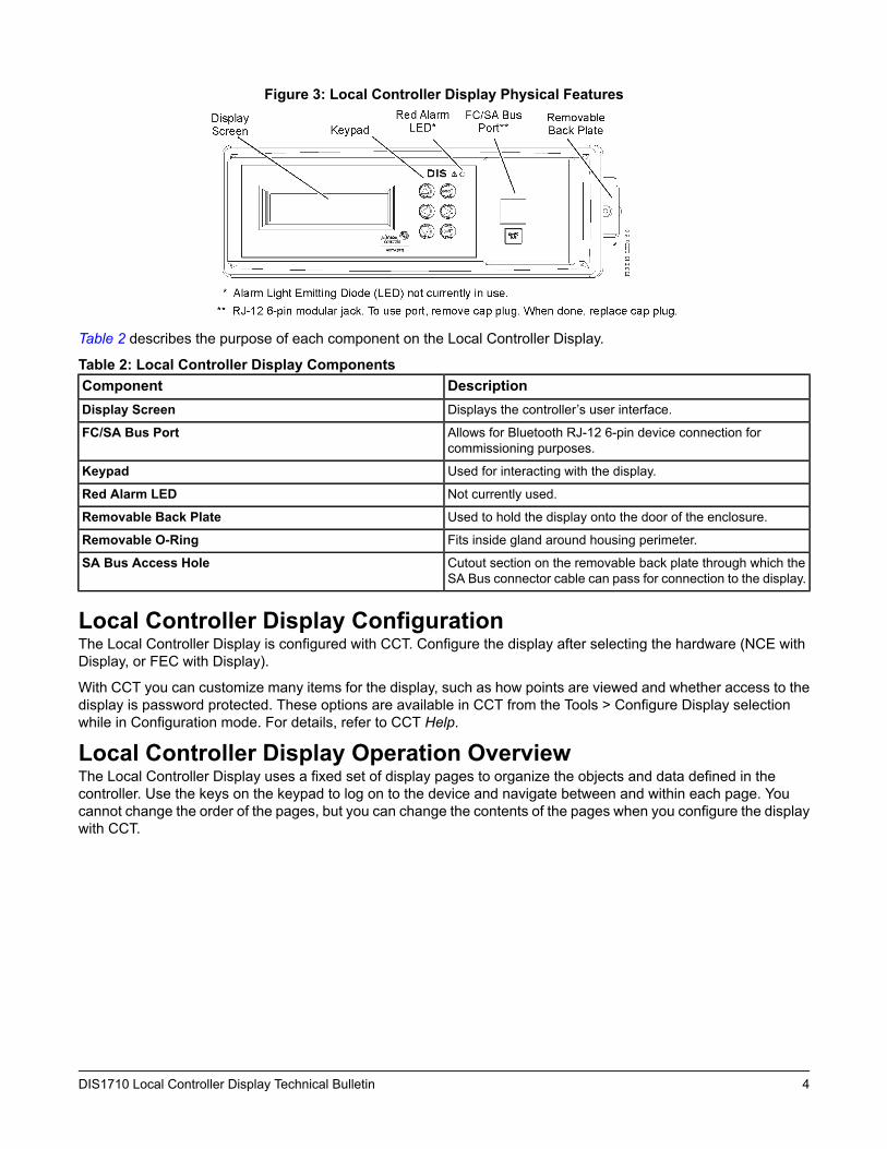
Figure 3: Local Controller Display Physical Features
Table 2 describes the purpose of each component on the Local Controller Display.
Table 2: Local Controller Display ComponentsDescriptionComponentDisplays the controller’s user interface.Display Screen
Allows for Bluetooth RJ-12 6-pin device connection forcommissioning purposes.
FC/SA Bus Port
Used for interacting with the display.Keypad
Not currently used.Red Alarm LED
Used to hold the display onto the door of the enclosure.Removable Back Plate
Fits inside gland around housing perimeter.Removable O-Ring
Cutout section on the removable back plate through which theSA Bus connector cable can pass for connection to the display.
SA Bus Access Hole
Local Controller Display ConfigurationThe Local Controller Display is configured with CCT. Configure the display after selecting the hardware (NCE withDisplay, or FEC with Display).
With CCT you can customize many items for the display, such as how points are viewed and whether access to thedisplay is password protected. These options are available in CCT from the Tools > Configure Display selectionwhile in Configuration mode. For details, refer to CCT Help.
Local Controller Display Operation OverviewThe Local Controller Display uses a fixed set of display pages to organize the objects and data defined in thecontroller. Use the keys on the keypad to log on to the device and navigate between and within each page. Youcannot change the order of the pages, but you can change the contents of the pages when you configure the displaywith CCT.
4DIS1710 Local Controller Display Technical Bulletin
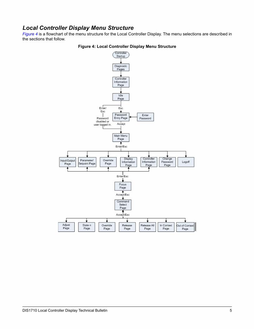
Local Controller Display Menu StructureFigure 4 is a flowchart of the menu structure for the Local Controller Display. The menu selections are described inthe sections that follow.
Figure 4: Local Controller Display Menu Structure
5DIS1710 Local Controller Display Technical Bulletin
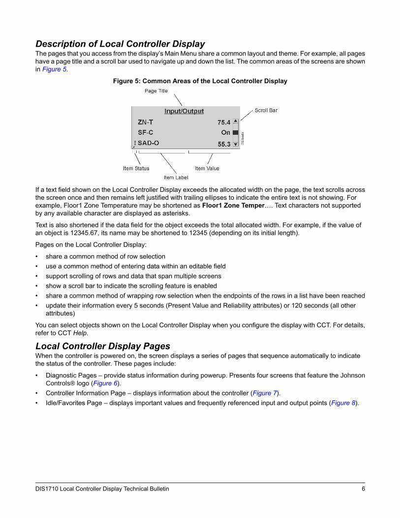
Description of Local Controller DisplayThe pages that you access from the display’s Main Menu share a common layout and theme. For example, all pageshave a page title and a scroll bar used to navigate up and down the list. The common areas of the screens are shownin Figure 5.
Figure 5: Common Areas of the Local Controller Display
If a text field shown on the Local Controller Display exceeds the allocated width on the page, the text scrolls acrossthe screen once and then remains left justified with trailing ellipses to indicate the entire text is not showing. Forexample, Floor1 Zone Temperature may be shortened as Floor1 Zone Temper…. Text characters not supportedby any available character are displayed as asterisks.
Text is also shortened if the data field for the object exceeds the total allocated width. For example, if the value ofan object is 12345.67, its name may be shortened to 12345 (depending on its initial length).
Pages on the Local Controller Display:
• share a common method of row selection• use a common method of entering data within an editable field• support scrolling of rows and data that span multiple screens• show a scroll bar to indicate the scrolling feature is enabled• share a common method of wrapping row selection when the endpoints of the rows in a list have been reached• update their information every 5 seconds (Present Value and Reliability attributes) or 120 seconds (all other
attributes)
You can select objects shown on the Local Controller Display when you configure the display with CCT. For details,refer to CCT Help.
Local Controller Display PagesWhen the controller is powered on, the screen displays a series of pages that sequence automatically to indicatethe status of the controller. These pages include:
• Diagnostic Pages – provide status information during powerup. Presents four screens that feature the JohnsonControls® logo (Figure 6).
• Controller Information Page – displays information about the controller (Figure 7).• Idle/Favorites Page – displays important values and frequently referenced input and output points (Figure 8).
6DIS1710 Local Controller Display Technical Bulletin
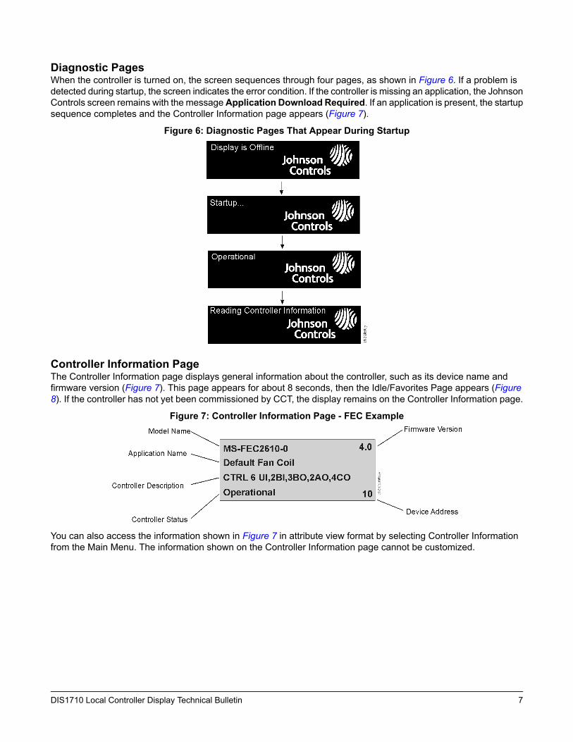
Diagnostic PagesWhen the controller is turned on, the screen sequences through four pages, as shown in Figure 6. If a problem isdetected during startup, the screen indicates the error condition. If the controller is missing an application, the JohnsonControls screen remains with the messageApplication Download Required. If an application is present, the startupsequence completes and the Controller Information page appears (Figure 7).
Figure 6: Diagnostic Pages That Appear During Startup
Controller Information PageThe Controller Information page displays general information about the controller, such as its device name andfirmware version (Figure 7). This page appears for about 8 seconds, then the Idle/Favorites Page appears (Figure8). If the controller has not yet been commissioned by CCT, the display remains on the Controller Information page.
Figure 7: Controller Information Page - FEC Example
You can also access the information shown in Figure 7 in attribute view format by selecting Controller Informationfrom the Main Menu. The information shown on the Controller Information page cannot be customized.
7DIS1710 Local Controller Display Technical Bulletin
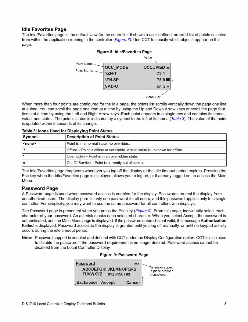
Idle Favorites PageThe Idle/Favorites page is the default view for the controller. It shows a user-defined, ordered list of points selectedfrom within the application running in the controller (Figure 8). Use CCT to specify which objects appear on thispage.
Figure 8: Idle/Favorites Page
When more than four points are configured for the Idle page, the points list scrolls vertically down the page one lineat a time. You can scroll the page one item at a time by using the Up and Down Arrow keys or scroll the page fouritems at a time by using the Left and Right Arrow keys. Each point appears in a single row and contains its name,value, and status. The point’s status is indicated by a symbol to the left of its name (Table 3). The value of the pointis updated within 5 seconds of its change.
Table 3: Icons Used for Displaying Point StatusDescription of Point StatusSymbolPoint is in a normal state; no overrides.<none>
Offline – Point is offline or unreliable. Actual value is unknown for offline.?
Overridden – Point is in an overridden state.*
Out Of Service – Point is currently out of service.¤
The Idle/Favorites page reappears whenever you log off the display or the idle timeout period expires. Pressing theEsc key when the Idle/Favorites page is displayed allows you to log on, or if already logged on, to access the MainMenu.
Password PageA Password page is used when password access is enabled for the display. Passwords protect the display fromunauthorized users. The display permits only one password for all users, and this password applies only to a singlecontroller. For simplicity, you may want to use the same password for all controllers with displays.
The Password page is presented when you press the Esc key (Figure 9). From this page, individually select eachcharacter of your password. An asterisk masks each selected character. When you select Accept, the password isauthenticated, and the Main Menu page is displayed. If the password entered is not valid, the messageAuthorizationFailed is displayed. Password access to the display is granted until you log off manually, or until no keypad activityoccurs during the idle timeout period.
Note: Password support is enabled and defined with CCT under the Display Configuration option. CCT is also usedto disable the password if the password requirement is no longer desired. Password access cannot bedisabled from the Local Controller Display.
Figure 9: Password Page
8DIS1710 Local Controller Display Technical Bulletin
Change Password PageOnce logged on, you can change your password by accessing the Change Password page. The process involvesentering, confirming, then saving the new password. The password can be from one to 32 characters in length, alluppercase alphanumeric characters. If the new password is not accepted, the appropriate user message appears.If the new password is accepted, the Main Menu page appears.
Figure 10: Change Password Page
Data Refresh RateData shown on the Local Controller Display is periodically refreshed. For monitored points, the refresh rate of thePresent Value and Reliability attributes is once every 5 seconds. For all other attributes, the refresh rate is within120 seconds. After 10 minutes with no keypad activity, the refresh rate of all attributes, including Present Value andReliability, reverts to 120 seconds.
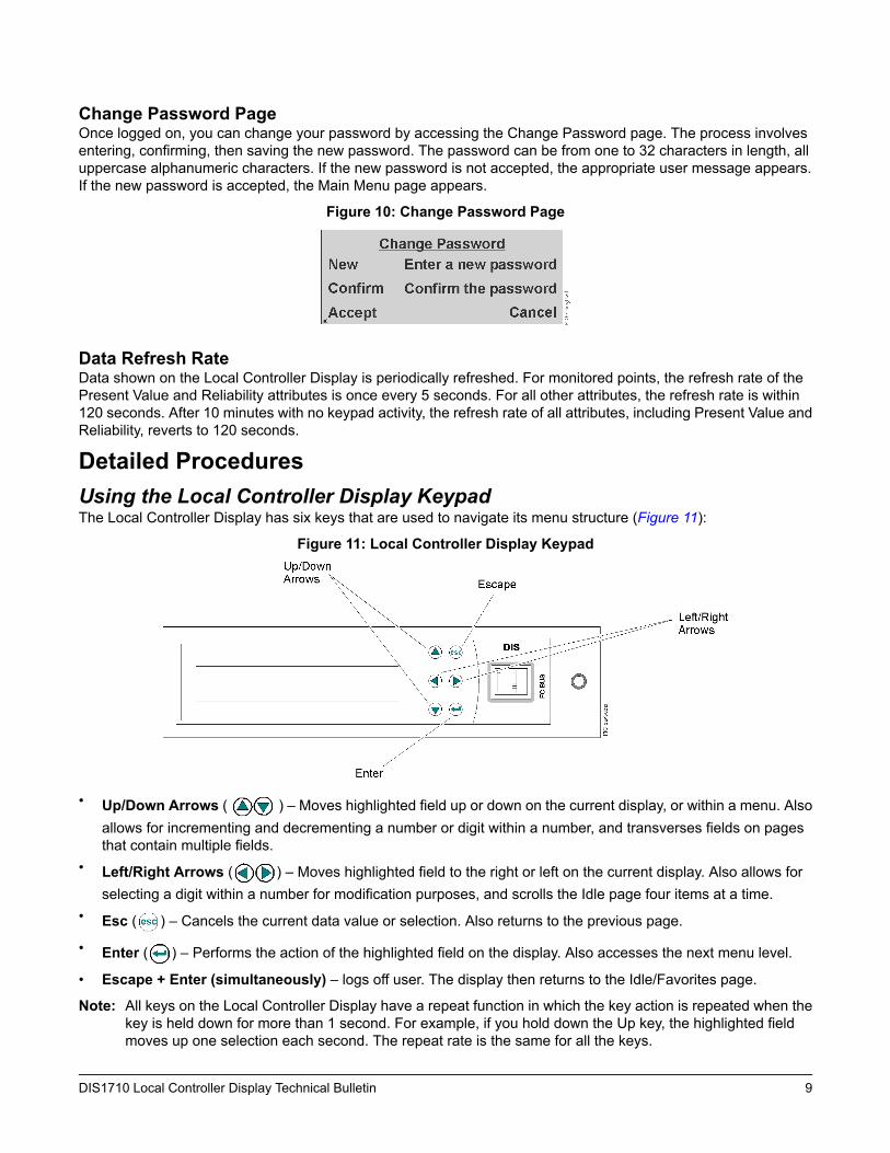
Detailed ProceduresUsing the Local Controller Display KeypadThe Local Controller Display has six keys that are used to navigate its menu structure (Figure 11):
Figure 11: Local Controller Display Keypad
• Up/Down Arrows ( ) – Moves highlighted field up or down on the current display, or within a menu. Alsoallows for incrementing and decrementing a number or digit within a number, and transverses fields on pagesthat contain multiple fields.
• Left/Right Arrows ( ) – Moves highlighted field to the right or left on the current display. Also allows forselecting a digit within a number for modification purposes, and scrolls the Idle page four items at a time.
• Esc ( ) – Cancels the current data value or selection. Also returns to the previous page.
• Enter ( ) – Performs the action of the highlighted field on the display. Also accesses the next menu level.
• Escape + Enter (simultaneously) – logs off user. The display then returns to the Idle/Favorites page.
Note: All keys on the Local Controller Display have a repeat function in which the key action is repeated when thekey is held down for more than 1 second. For example, if you hold down the Up key, the highlighted fieldmoves up one selection each second. The repeat rate is the same for all the keys.
9DIS1710 Local Controller Display Technical Bulletin

Entering a PasswordTo enter a password:Note: The password entry page is available only if a password was enabled when the Display Configuration was
set with CCT. Otherwise, the display menus are accessible without a password entry.
1. Press the Escape or Enter key. The Password page appears.
Figure 12: Password Entry Page
2. Use the Arrow keys to select each character of your password, and press Enter to submit each character. Yourentries appear in the upper right corner as asterisks. To correct an entry, use Backspace to erase one entry ata time, or press to clear the entire password and start over.
3. When you have entered the entire password, select Accept and press Enter. The password is verified and theMain Menu appears.
Changing the PasswordTo change the password:
1. Go to the Main Menu.2. Scroll down and select the Change Password option.3. Press Enter. The Change Password page appears (Figure 13).
Figure 13: Change Password Page
4. Select the Enter a new password option. The New password entry page appears (Figure 14).
Figure 14: New Password Page
5. Use the Arrow keys to select each character of your new password, and press Enter to submit each character.Your entries appear in the upper right corner as asterisks. To correct an entry, use Backspace to erase onecharacter at a time, or press Escape to clear the entire password and start over.
6. When you have entered the entire password, selectAccept and press Enter. The Change Password confirmationpage appears (Figure 15).
10DIS1710 Local Controller Display Technical Bulletin

Figure 15: Change Password Page
7. Press Enter to confirm the new password. The Confirm password page appears (Figure 16).
Figure 16: Confirm Password Page
8. Reenter your new password, selectAccept, and pressEnter. The Change Password confirmation page reappears(Figure 17).
Figure 17: Change Password Page
9. Select Accept and press Enter. The new password is confirmed and, if accepted, the Main Menu appears. Ifthe new and confirmed password entries do not match, the message Passwords do not match displays.
Note: You can also change your password using CCT. The new password is effective after you re-downloadthe application to the controller using CCT.
Displaying Configured Input and Output PointsTo display configured input and output points:
1. Go to the Main Menu.2. Select the Input/Output option. A list of all configured input and output points appears (Figure 18).
Figure 18: Input/Output Page
3. Use the Up/Down Arrow keys to scroll through the list of points and their current values.4. To get more information on a particular point, select the point and press Enter. The focus page for the point
appears. Figure 19 is an example of a zone setpoint.
11DIS1710 Local Controller Display Technical Bulletin
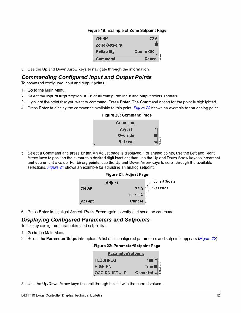
Figure 19: Example of Zone Setpoint Page
5. Use the Up and Down Arrow keys to navigate through the information.
Commanding Configured Input and Output PointsTo command configured input and output points:
1. Go to the Main Menu.2. Select the Input/Output option. A list of all configured input and output points appears.3. Highlight the point that you want to command. Press Enter. The Command option for the point is highlighted.4. Press Enter to display the commands available to this point. Figure 20 shows an example for an analog point.
Figure 20: Command Page
5. Select a Command and press Enter. An Adjust page is displayed. For analog points, use the Left and RightArrow keys to position the cursor to a desired digit location; then use the Up and Down Arrow keys to incrementand decrement a value. For binary points, use the Up and Down Arrow keys to scroll through the availableselections. Figure 21 shows an example for adjusting an analog setpoint.
Figure 21: Adjust Page
6. Press Enter to highlight Accept. Press Enter again to verify and send the command.
Displaying Configured Parameters and SetpointsTo display configured parameters and setpoints:
1. Go to the Main Menu.2. Select the Parameter/Setpoints option. A list of all configured parameters and setpoints appears (Figure 22).
Figure 22: Parameter/Setpoint Page
3. Use the Up/Down Arrow keys to scroll through the list with the current values.
12DIS1710 Local Controller Display Technical Bulletin
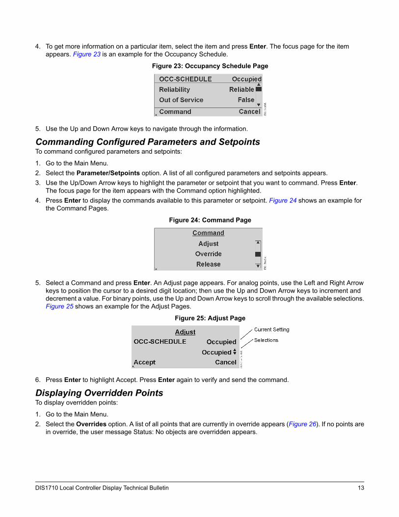
4. To get more information on a particular item, select the item and press Enter. The focus page for the itemappears. Figure 23 is an example for the Occupancy Schedule.
Figure 23: Occupancy Schedule Page
5. Use the Up and Down Arrow keys to navigate through the information.
Commanding Configured Parameters and SetpointsTo command configured parameters and setpoints:
1. Go to the Main Menu.2. Select the Parameter/Setpoints option. A list of all configured parameters and setpoints appears.3. Use the Up/Down Arrow keys to highlight the parameter or setpoint that you want to command. Press Enter.
The focus page for the item appears with the Command option highlighted.4. Press Enter to display the commands available to this parameter or setpoint. Figure 24 shows an example for
the Command Pages.
Figure 24: Command Page
5. Select a Command and press Enter. An Adjust page appears. For analog points, use the Left and Right Arrowkeys to position the cursor to a desired digit location; then use the Up and Down Arrow keys to increment anddecrement a value. For binary points, use the Up and Down Arrow keys to scroll through the available selections.Figure 25 shows an example for the Adjust Pages.
Figure 25: Adjust Page
6. Press Enter to highlight Accept. Press Enter again to verify and send the command.
Displaying Overridden PointsTo display overridden points:
1. Go to the Main Menu.2. Select the Overrides option. A list of all points that are currently in override appears (Figure 26). If no points are
in override, the user message Status: No objects are overridden appears.
13DIS1710 Local Controller Display Technical Bulletin
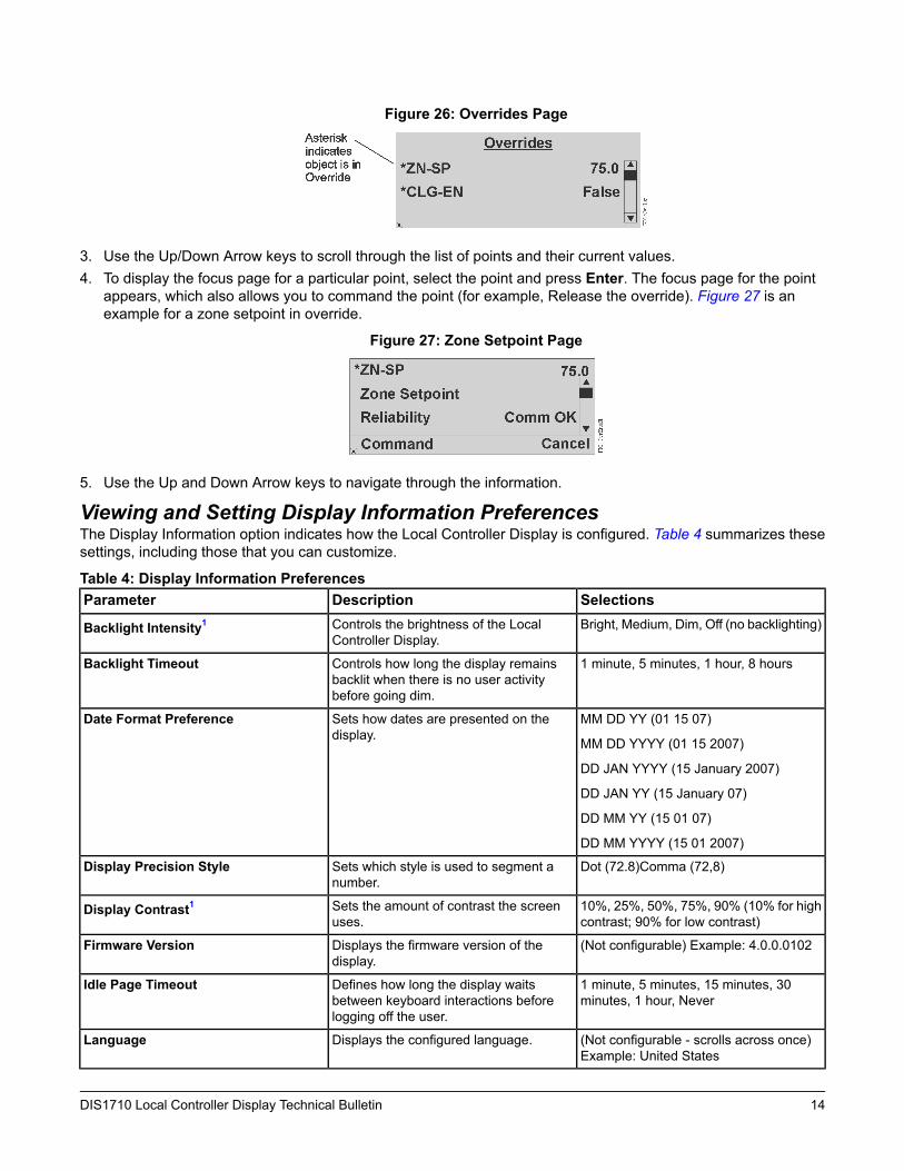
Figure 26: Overrides Page
3. Use the Up/Down Arrow keys to scroll through the list of points and their current values.4. To display the focus page for a particular point, select the point and press Enter. The focus page for the point
appears, which also allows you to command the point (for example, Release the override). Figure 27 is anexample for a zone setpoint in override.
Figure 27: Zone Setpoint Page
5. Use the Up and Down Arrow keys to navigate through the information.
Viewing and Setting Display Information PreferencesThe Display Information option indicates how the Local Controller Display is configured. Table 4 summarizes thesesettings, including those that you can customize.
Table 4: Display Information PreferencesSelectionsDescriptionParameterBright, Medium, Dim, Off (no backlighting)Controls the brightness of the Local
Controller Display.Backlight Intensity1
1 minute, 5 minutes, 1 hour, 8 hoursControls how long the display remainsbacklit when there is no user activitybefore going dim.
Backlight Timeout
MM DD YY (01 15 07)
MM DD YYYY (01 15 2007)
DD JAN YYYY (15 January 2007)
DD JAN YY (15 January 07)
DD MM YY (15 01 07)
DD MM YYYY (15 01 2007)
Sets how dates are presented on thedisplay.
Date Format Preference
Dot (72.8)Comma (72,8)Sets which style is used to segment anumber.
Display Precision Style
10%, 25%, 50%, 75%, 90% (10% for highcontrast; 90% for low contrast)
Sets the amount of contrast the screenuses.
Display Contrast1
(Not configurable) Example: 4.0.0.0102Displays the firmware version of thedisplay.
Firmware Version
1 minute, 5 minutes, 15 minutes, 30minutes, 1 hour, Never
Defines how long the display waitsbetween keyboard interactions beforelogging off the user.
Idle Page Timeout
(Not configurable - scrolls across once)Example: United States
Displays the configured language.Language
14DIS1710 Local Controller Display Technical Bulletin

Table 4: Display Information PreferencesSelectionsDescriptionParameter(Not configurable) Example: 22Displays the controller’s configured Media
Access Control (MAC) address.MAC Address
(Not configurable) Example: 38,400Displays the controller’s configuredMS/TPbaud rate.
MS/TP Baud Rate
12 MM (4:30)
12 MM SS (4:30:30)
12 MM AMPM (4:30 PM)
12 MM SS AMPM (4:30:30 PM)
24 MM (16:30)
24 MM SS (16:30:30)
Sets how time of day is presented on thedisplay.
Time Format Preference
1 Backlight intensity and display contrast both affect the readability of the display. Best visibility is backlight intensity = bright anddisplay contrast = 10%. Worst visibility is backlight intensity = off and display contrast = 90%.
Setting the Backlight IntensityTo set the backlight intensity:
1. Go to the Main Menu.2. Scroll down and select the Display Information option.3. Scroll down and select the Backlight Intensity parameter.4. On the Modify page, use the Up/Down Arrow keys to select a backlight intensity (Figure 28). The screen changes
as you select an intensity level.
Figure 28: Modify Backlight Intensity Page
5. Press Enter to highlight Accept. Press Enter again to save the setting.
Setting the Backlight TimeoutTo set the backlight timeout:
1. Go to the Main Menu.2. Scroll down and select the Display Information option.3. Scroll down and select the Backlight Timeout parameter.4. On the Modify page, use the Up/Down Arrow keys to select a backlight timeout (Figure 29).
Figure 29: Modify Backlight Timeout Page
5. Press Enter to highlight Accept. Press Enter again to save the setting.
15DIS1710 Local Controller Display Technical Bulletin
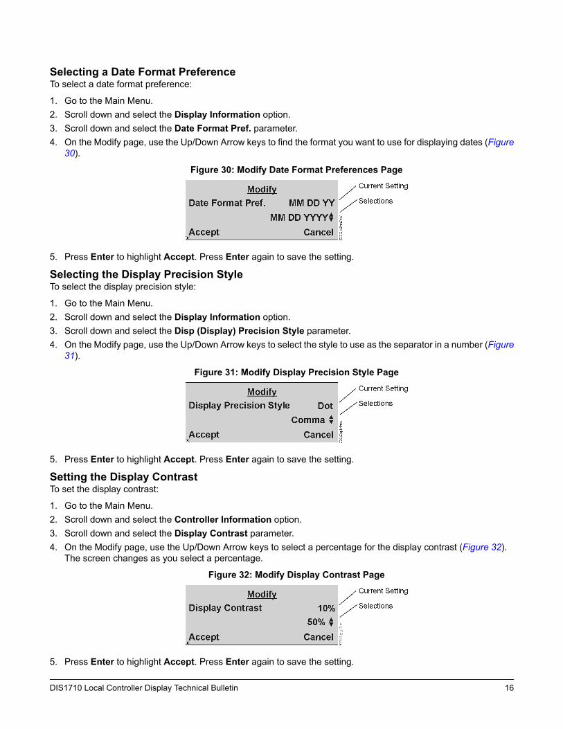
Selecting a Date Format PreferenceTo select a date format preference:
1. Go to the Main Menu.2. Scroll down and select the Display Information option.3. Scroll down and select the Date Format Pref. parameter.4. On the Modify page, use the Up/Down Arrow keys to find the format you want to use for displaying dates (Figure
30).
Figure 30: Modify Date Format Preferences Page
5. Press Enter to highlight Accept. Press Enter again to save the setting.
Selecting the Display Precision StyleTo select the display precision style:
1. Go to the Main Menu.2. Scroll down and select the Display Information option.3. Scroll down and select the Disp (Display) Precision Style parameter.4. On the Modify page, use the Up/Down Arrow keys to select the style to use as the separator in a number (Figure
31).
Figure 31: Modify Display Precision Style Page
5. Press Enter to highlight Accept. Press Enter again to save the setting.
Setting the Display ContrastTo set the display contrast:
1. Go to the Main Menu.2. Scroll down and select the Controller Information option.3. Scroll down and select the Display Contrast parameter.4. On the Modify page, use the Up/Down Arrow keys to select a percentage for the display contrast (Figure 32).
The screen changes as you select a percentage.
Figure 32: Modify Display Contrast Page
5. Press Enter to highlight Accept. Press Enter again to save the setting.
16DIS1710 Local Controller Display Technical Bulletin

Setting the Idle Timeout ValueTo set the auto-logoff timeout value:
1. Go to the Main Menu.2. Scroll down and select the Display Information option.3. Scroll down and select the Idle Page Timeout parameter.4. On the Modify page, use the Up/Down Arrow keys to select a new idle timeout value (Figure 33).
Figure 33: Modify Idle Page Timeout Page
5. Press Enter to highlight Accept. Press Enter again to save the setting.
Selecting the Time Format PreferenceTo select a time format preference:
1. Go to the Main Menu.2. Scroll down and select the Display Information option.3. Scroll down and select the Time Format Preference parameter.4. On the Modify page, use the Up/Down Arrow keys to find the format you want to use for displaying times (Figure
34).
Figure 34: Modify Time Format Preference Page
5. Press Enter to highlight Accept. Press Enter again to save the setting.
Displaying Controller InformationTo display controller information:
1. Go to the Main Menu.2. Scroll down and select the Controller Information option.3. Scroll down to view each line of controller information. Table 5 lists the type of information available. None of
these attributes can be modified from the display, but some are defined when the application is configured usingCCT.
Table 5: Controller Display AttributesExampleDescriptionAttributeOperationalCurrent status of the controllerStatus1
6 UI, 2 BI, 3 BO, 2 AO, 4 COList of the controller’s point capacitiesCTRL
MS-FEC2611-0Model name of the controllerModel Name
FC-22Object name of the controllerObject Name2
17DIS1710 Local Controller Display Technical Bulletin

Table 5: Controller Display AttributesExampleDescriptionAttributeFCappName of the system application in the
controllerSystem Name2
NAE00108d00c9033Name of the site director for this fieldcontroller
Local Site Director
5.1Version of the firmware stored in thecontroller
Firmware Version
6Number representing the current CentralProcessing Unit (CPU) usage in percent
CPU Usage
10Number representing the MAC addressassigned to the controller
FCB Mac Address
AutoBaud rate configured for communicationon the Master-Slave/Token Passing(MS/TP) Bus
FCB Baud Rate
1 No attribute label called Status is shown; only the current status of the controller is indicated.2 This attribute is defined when the application is configured using CCT.3 When a site director is not defined or is not online, this field contains four asterisks (****).
Logging Off the DisplayTo log off the display:
1. Go to the Main Menu.2. Scroll down and select the Log Off option.3. Press Enter. You are logged off and the Idle/Favorites page appears.
Note: You may also log off by pressing the Esc and Enter keys at the same time.
Configuring the Local Controller Display with CCTNCE and FEC controllers with a display, or controllers with the remote stand-alone display, are configured with CCT.The CCT provides a Configure Display menu option that allows you to:
• define which points appear on the display pages (Input/Output View, Parameter/Setpoint View, and Idle View)and in which order
• define which points are read only (cannot be commanded using the display)• specify point names and descriptions• set display attributes including contrast and backlight intensity• select timeout settings• select authorization including password definition
After configuring the display, you can download the application to the controller with CCT. The changes then becomeeffective. For details, refer to CCT Help.
18DIS1710 Local Controller Display Technical Bulletin

Technical SpecificationsTable 6: DIS1710 Local Controller Display
MS-DIS1710-0 Local Controller Display for Field Equipment ControllersProduct Code Number
Nominal 15 V provided by controller over SA BusPower Requirement
2 VA maximumPower Consumption
0 to 50°C (32 to 122°F)Ambient Operating Temperature
10 to 90% RH, 30°C (86°F) maximum dew pointAmbient Operating Conditions
-40 to 70°C (-40 to 158°F)Ambient Storage Temperature
5 to 95% RH, 30°C (86°F) maximum dew pointAmbient Storage Conditions
RJ-12 6-pin jack at Service Port (covered by removable cap-plug) SA Bus connection onback of unit
Terminations
Renesas® H8S-2398 16-bit microprocessorProcessor
256 KB Flash Memory8 KB Random Access Memory (RAM)Memory
RTOS-H8SOperating System
Communication to controller over SA BusNetwork and Serial Interfaces
240 x 64 pixels with white LED backlighting (adjustable)Graphic Display Resolution
85.9 x 238 x 25.8 mm (3.4 x 9.37 x 1.0 in.)Dimensions (Height x Width xDepth)
Plastic housing material: ABS + polycarbonate Protection: IP20 (IEC60529)Housing
Mount to the outside of the enclosure 70.5 x 216.5 mm (2.78 x 8.525 in.)Mounting (Height x Width)
United States: UL Listed, File E107041, CCNPAZX, UL 916, EnergyManagement EquipmentFCC Compliant to CFR47, Part 15, Subpart B, Class A
Compliance
Canada: UL Listed, File E107041, CCNPAZX7, CAN/CSAC22.2 No. 205, Signal Equipment;Industry Canada Compliant, ICES-003
Europe: CE Mark – Johnson Controls, Inc., declares that this product is in compliance withthe essential requirements and other relevant provisions of the EMCDirective 2004/108/EC.
Australia and New Zealand: C-Tick Mark, Australia/NZ Emissions Compliant
0.14 kg (0.3 lb)Shipping Weight
The performance specifications are nominal and conform to acceptable industry standard. For application at conditionsbeyond these specifications, consult the local Johnson Controls office. Johnson Controls, Inc. shall not be liable fordamages resulting from misapplication or misuse of its products.
Building Efficiency507 E. Michigan Street, Milwaukee, WI 53202
Metasys® and Johnson Controls® are registered trademarks of Johnson Controls, Inc.All other marks herein are the marks of their respective owners. © 2013 Johnson Controls, Inc.
www.johnsoncontrols.comPublished in U.S.A.
19DIS1710 Local Controller Display Technical Bulletin