dmu navigator preface - catia - serwis informacyjny navigator preface what's new ? getting...
TRANSCRIPT

DMU Navigator
Preface
What's New ?
Getting Started
Basic Tasks
Workbench Description
Customizing
Glossary
Index
© Dassault Systèmes 1994-99. All rights reserved.

PrefaceDMU Navigator Version 5 addresses Digital Mock-Up (DMU) process centric designand review requirements of the extended enterprise. It offers a scalable solutioncapable of handling digital mock-ups of all sizes, ranging from consumer goods to verylarge automotive, aerospace, plant, ship and heavy machinery mock-ups.
Available on both UNIX and Windows environments, DMU Navigator is built to betotally compliant with Windows presentation standards.
DMU Navigator Version 5 comprises the following main applications:Kinematics SimulatorFitting SimulatorSpace Analysis
The above applications are delivered as totally interoperable workbenches. From auser interface standpoint, switching from one to another is completely transparent anddone in a context-sensitive fashion. In addition, to these workbenches, DMU Navigatoris an open solution which offers:
Support of native CATIA Version 4 and Version 5 dataInterface with the VRML industry standard for data exchangeNative OLE (Object Linking and Embedding) compliance. This facilitates thesystem integration within the office environment and across the digitalenterprise.
DMU Kinematics Simulator
Offers motion simulation capabilities. Kinematics Simulator can be cooperativelyused with other current or future companion products of the DMU Navigator nextgeneration such as DMU Fitting Simulator and DMU Space Analysis.
DMU Fitting Simulator
Allows the user to define and simulate assembly and disassembly proceduresthereby validating product assembly and maintenance at the design stage.Fitting Simulator can be cooperatively used with other current or futurecompanion products of the DMU Navigator next generation such as KinematicsSimulator and Space Analysis.
DMU Space Analysis

Offers advanced interference analysis, sectioning and measurementcapabilities. Space Analysis can be cooperatively used with other current orfuture companion products of the DMU Navigator next generation such as DMUKinematics Simulator and Fitting Simulator.
DMU OptimizerImproves user's productivity by computing an optimized representation of datafor mockup verification in the context of the immersive and collaborative designreview environment of the full digital mockup.
DMU Optimzer is a dedicated DMU Navigator workbench and is available on bothUNIX and Windows NT environments.
Using This GuideThis guide is the DMU Navigator Version 5 User's Guide.
To get the most out of DMU Navigator, use the following user guide wizard. It will helpyou better locate information relevant to you as well as to the way you work.
User Guide Wizard
Go to:
I am a first time userThe getting started tutorial. Once you have finished, youshould move on to the user task section of this guide. Thissteps you through basic procedures.
I have used DMUNavigator before
Your DMU Navigator Version 5 session and start reviewingyour own documents. If you need some help inunderstanding tools and commands, use the on-line help.You can also take a look at the basic user task section ofthis guide to locate information with which you are notalready familiar.

Where to Find More InformationPrior to reading this book, we recommend that you read the Infrastructure User'sGuide.
Note: You can start a DMU Navigator session by entering the command dmu(Windows) or DMU (UNIX). This starts the default DMU Navigator Version 5environment.
You may also like to read the following complementary product guides, for which theappropriate license is required.
DMU Fitting Simulator User's GuideDMU Kinematics Simulator User's GuideDMU Space Analysis User's Guide.DMU Optimizer User's Guide

What's New?Enhanced Fly mode:
the compass is no longer usedsupport for bankingwhen colliding with solid objects when flying, you now slide along the object surfaceinstead of flying through the object
New: Separate overview window for viewing geometry
Enhanced: Transforming 2D markers into 3D markers in and moving markers in:
Using the 2D Marker
Enhanced: Animate viewpoint - automatic insert and Edit simulation objects in:
Recording AnimationsReplaying Animations
New: Generating an Animation
New: Scenes in:About Scenes,Adding a Component,Replacing a Component,Removing a ComponentManaging an Exploded View
New: Proximity Query in:Running Proximity Query (DMU Navigator license only)Running Proximity Query (DMU Navigator & Optimizer)

Getting StartedThis tutorial will guide you step-by-step through your first DMU Navigatorsession, allowing you to get acquainted with the product.You will need a DMU Navigator V5 session and should be familiar with basicconcepts such as document windows, standard and view toolbars.You should be able to complete this tutorial in about 15 minutes.
Task

Entering the DMU Navigator WorkbenchThis task shows you how to enter the DMU Navigator workbench and create a new document.
1. Select Digital Mockup -> DMU Navigator from the Start menu
The DMU Navigator workbench is displayed and a document like this will appear:
Note that more toolbars may appear next to the Standard toolbar when you create a document.

Inserting ComponentsThis task shows you how to insert components into a DMU Navigator document.
1. Select the Insert -> Existing Component... command
If the menu item cannot be selected, right-click product1 in the specification tree and select ExistingComponent... from the contextual menu.2. In the Insert an Existing Component dialog box, specify the file location for the model of interest:the platform.model document from the \online\samples\dmunavigator directory.3. Click the Files of type drop-down list and select the model type4. Double-click the platform.model to insert it into your DMU Navigator documentThe DMU Navigator document now looks like this:


Navigating in Examine ModeNavigating in Examine Mode is the default mode. You can examine your document asyou would from the outside by moving around the document's perimeter, or as youwould from within, turning your head to view or moving closer (zoom in, zoom out) todifferent objects.This task shows you how to rotate, zoom and move your document.
Open the platform.model document from the \online\samples\dmunavigator directory.
1. Press and hold down the middle mouse button, then the left mouse button, anddrag (still holding both buttons down) to rotate
2. Press and hold down the middle mouse button, then click the left mouse buttonand drag (still holding the middle mouse button down) to zoom:
Dragging towards 12 o'clock zooms in on your document; dragging towards 6o'clock zooms out of your document.
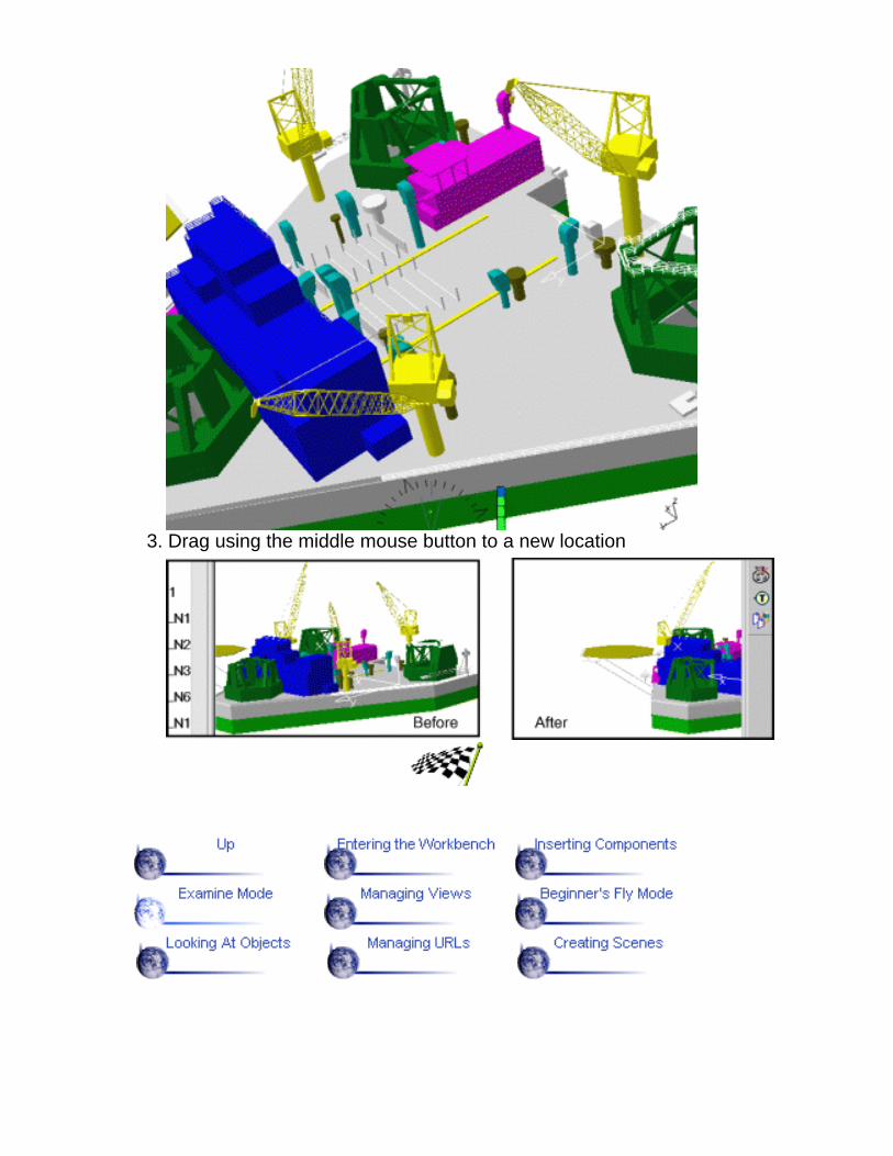
3. Drag using the middle mouse button to a new location

Managing ViewsThis task shows you how to create and annotate a user-defined view.
Open the platform.model document from the \online\samples\dmunavigatordirectory.
1. Select the View->Named Views... command:
The Named Views dialog box appears listing standard views you can useto display the document2. Double-click the iso view to obtain an isometric view of your document:
You can now customize this view3. Adjust the different view parameters (zoom, rotation, etc.) until you arehappy with the result
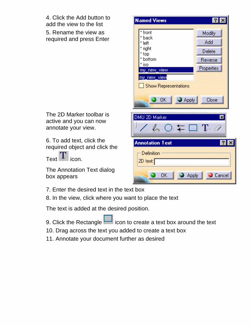
4. Click the Add button toadd the view to the list5. Rename the view asrequired and press Enter
The 2D Marker toolbar isactive and you can nowannotate your view.
6. To add text, click therequired object and click the
Text icon.
The Annotation Text dialogbox appears
7. Enter the desired text in the text box8. In the view, click where you want to place the text
The text is added at the desired position.
9. Click the Rectangle icon to create a text box around the text10. Drag across the text you added to create a text box11. Annotate your document further as desired


Navigating in Beginner's Fly ModeThis task shows you how to navigate through a document in beginner's fly mode. In beginner'sfly mode you can move upward or downward on any horizontal view plane as you moveforward.
Open the platform.model document from the \online\samples\dmunavigator directory.
1. Click the Fly icon in the View toolbar:
The toolbar expands to include four icons that you will use to navigate through yourdocument.
The horizontal indicator to the right of the compass helps you keep track of yourhorizontal view plane.
2. Click the Turn Head icon then drag (left mouse button) to define your startingposition
3. Release at desired location
4. Click the Fly icon, then click the left mouse button to begin to flying:
You begin to fly forward in the chosen direction
A small orange rectangle appears as you fly. This rectangle represents a neutralzone and an imaginary horizontal line running through the center of it defines the upand the down. 5. Still holding the left button down, drag left or right to change direction:6. Bring the cursor back into the orange rectangle to continue flying forward in the newdirection

7. To modify your speed, click the Accelerate or Decelerate icon one or more times,then click the Fly icon again followed by the left mouse button to pursue your fly
Note: The size of the arrow in the navigation compass reflects the speed of your fly.
8. Click the Examine mode icon in the View toolbar to return to the defaultnavigation mode

Looking At ObjectsDuring the course of your inspection, you may want to concentrate on a particularobject and view it closer up. Changing the target lets you dynamically redefineyour target and viewing distance.This task explains how to look at the document in a specific direction by targetingthrough a user-defined viewport.Open the platform.model document from the \online\samples\dmunavigatordirectory.
1. Click the Look At icon in the DMU Viewing toolbar.2. Click (left mouse button) on an object in the document to select it3. Drag (still holding left mouse button down) slowly to display the viewport.
As you begin to drag, a rectangle with two diagonals appears andcontinues to grow as long as you continue to drag. This rectanglerepresents the viewing window of the future view.4. Continue dragging to move around, resize and reposition the viewport.
The viewport is then shaped like a pyramid: your eyepoint is located at thevertex of the pyramid. You can resize the viewport by dragging the middlemouse button.
5. Release the button.
You now see what is targeted inside the viewport.


Managing URLsYou can add hyperlinks to your document and then use them to jump to a variety of locations, for example to a marketing presentation, a Microsoft Excel spreadsheet or a HTML page on theintranet.This task explains how to add hyperlinks.
You should prepare a document that you want to see displayed via a hyperlink.
1. Select the object you want to represent the hyperlink.
2. Select the Insert-> Add Hyperlinks command
The Manage Hyperlink dialog box appears.
3. Enter a name identifying your hyperlink
4. Click Browse... and select the file in the Link to File dialog box5. Click OK in the Insert Hyperlink dialog box
You can now test the link you added.5. Select the object to which you just added the hyperlink
6. Click the Go to Hyperlinks icon in the DMU Data Navigation toolbar
The file linked is displayed.
This concludes the step-by-step getting started scenario.
You should now go to the user task section of this guide. This steps you through basic procedures, letting you get the most out of this product.
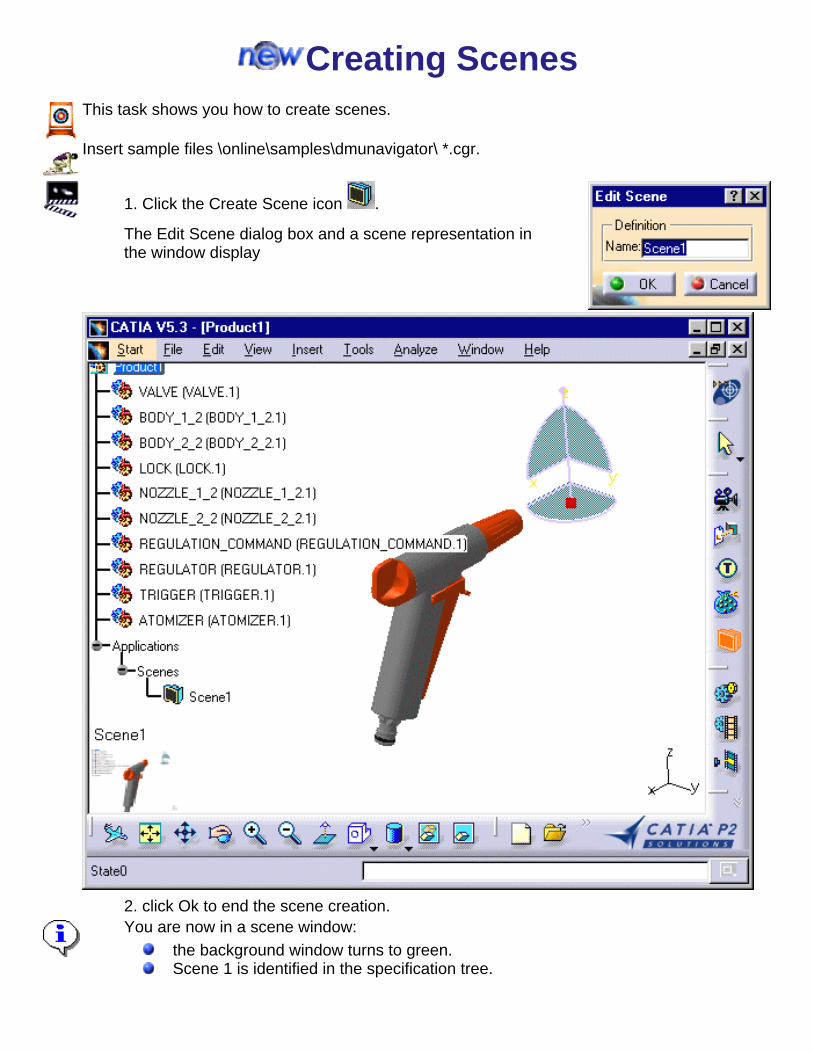
Creating ScenesThis task shows you how to create scenes.
Insert sample files \online\samples\dmunavigator\ *.cgr.
1. Click the Create Scene icon .
The Edit Scene dialog box and a scene representation inthe window display
2. click Ok to end the scene creation.You are now in a scene window:
the background window turns to green.Scene 1 is identified in the specification tree.

3. Perform the required modifications. For instance modify the viewpoint.
4. Click the Exit From Scene icon to swap to the initial window.
The scene is updated.

5. Double-click Scene 1 either in the specification tree or in the geometry area to swap tothe scene window.6. Create as many scenes as needed.

Basic TasksTheme Purpose
Enter the DMU Navigator workbench and insertcomponents, define groups of products as well asview the current selection and content of the datacacheNavigate using the fly mode, view objects, definedocument viewpoints and set light and deptheffects Annotate documents, create hyperlinks, usestandard and user-defined views, use 2D and temporary markers Use cameras to create animations, record andreplay animations Record and replay animations. Generate an AVIfile.Use scene functionality to add and remove acomponent, use scene with the explodecommandSimplify an assemby

Setting Up Your DMU NavigatorSession
Task Purpose
Start a DMU Navigator session
Insert components
Import CAD Parts
Define groups of products
View the objects in the current selection
View the contents of the data cache

Entering the DMU Navigator WorkbenchThis task shows you how to enter the DMU Navigator workbench and open a new document.
1. Select Digital Mockup->DMU Navigator from the Start menu
The DMU Navigator workbench is loaded and a DMU Navigator document opens:
The DMU Navigator workbench comprises:A specification tree and a geometry areaSpecific toolbarsA number of contextual commands available in the both the specification tree and the geometryarea.
Clicking off View -> Specifications visible in the menu bar removes the specification tree and lets youuse the entire screen for the geometry.

Inserting ComponentsThis task shows you how to insert components into a DMU Navigator document.
Open the .cgr files from the \online\samples\dmunavigator directory.
1. Select the Insert -> Existing Component... command
If the menu item cannot be selected, right-click product1 in the specification tree and select ExistingComponent... from the contextual menu.2. In the Insert an Existing Component dialog box, select the file location
3. Click the Files of type: list
4. Select the desired type from the following:cgr (*.cgr)V4 model (*.model)CATpart (*.CATpart)CATproduct (*.CATproduct)V4 session (*.session)VRML 1.0.obj (*.obj)byu (*.byu)igespdb (*.pdb)stl (ASCII and binary) (*.stl)
Models, parts and products are loaded in visualization mode, i.e. without associated technological data(only visualization data is loaded). To access technological data, you must switch to design mode. Thisis done by selecting components inserted in the specification tree and then Edit -> Design Mode fromthe menu bar.5. Click Open in the dialog box
The DMU Navigator document now looks like this:

You can load the product structure only and then specify which 3D representations to insert. For
more information, see Loading the Product Structure Only.Adding CDM Products: For more information, see Adding a CDM Product to a Product on UNIX aswell as Customizing CDMA Data in Catia Version 5 on UNIX in the V4 Integration User's Guide.
Reading Parts and Assemblies from VPM-1: For information on reading parts and assemblies inVPM-1, please refer to Building a V5 product from a VPM1-PSN Window in the V4 Integration User'sGuide.
Open to MultiCAD:
If you want to import a CAD part which is not directly supported by DMU Navigator, you can run abackground converter that will output one of the following formats: cgr; pdb (Deneb part), vrml or stl.The CAD part files you want to import must have the .prt extension.The DMUNAV_CONVCOMMAND environment variable must be given the name of the conversioncommand as value. This command can be a .bat script on Windows or a shell script on UNIX. It has thefollowing arguments:
input filefull path of the cgr, pdb, vrml or stl file to be created in the data cache, depending on the formatchosen
The command must return 0 if it completes successfully and 1 if an error occurs.
Once the DMUNAV_CONVCOMMAND environment variable is defined, the .prt extension is proposedin the Insert Existing Component command. If you select a file with this extension, the command definedby the DMUNAV_CONVCOMMAND environment variable is run.
Each time a CATProduct containing a reference to such a part is re-read, the data cache is searched forthe up-to-date file. If no up-to-date file is found, the command defined by the

DMUNAV_CONVCOMMAND environment variable is re-run.
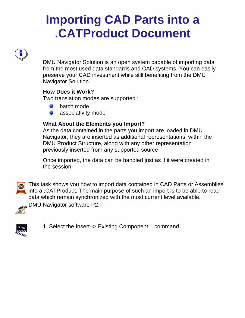
Importing CAD Parts into a.CATProduct Document
DMU Navigator Solution is an open system capable of importing datafrom the most used data standards and CAD systems. You can easilypreserve your CAD investment while still benefiting from the DMUNavigator Solution.
How Does it Work?Two translation modes are supported :
batch modeassociativity mode
What About the Elements you Import?As the data contained in the parts you import are loaded in DMUNavigator, they are inserted as additional representations within theDMU Product Structure, along with any other representationpreviously inserted from any supported source
Once imported, the data can be handled just as if it were created inthe session.
This task shows you how to import data contained in CAD Parts or Assembliesinto a .CATProduct. The main purpose of such an import is to be able to readdata which remain synchronized with the most current level available.DMU Navigator software P2.
1. Select the Insert -> Existing Component... command

If the menu item cannot be selected, right-click product 1 in the specification treeand select Existing Component... from the contextual menu.
2. In the Insert an Existing Component dialog box, select the filelocation
3. Click the Files of type: list
4. Select the desired type from the following:.prt.asm
Models, parts and products are loaded in visualization mode, i.e.without associated technological data (only visualization data isloaded). To access technological data, you must switch to designmode. This is done by selecting components inserted in thespecification tree and then Edit -> Design Mode from the menu bar.To set external formats import settings, see Customizing ExternalFormats Import
5. Click Open in the dialog box.


Defining Groups of ProductsThis task explains how to define groups of products.
A group is a set of products defined explicitly by selecting products individually.Groups are persistent and can be stored in the document.
Open the *.cgr files from the \online\samples\dmunavigator directory.
1. Select a product in the geometry area or in the specification tree2. Ctrl-click other products to add them to the initial selection
3. Select Insert -> Group... from the menu bar or click the Group icon inthe DMU Navigator Tools toolbar to create a group:

TheEditGroupdialogbox andthePreviewwindowappear.
ThePreviewwindowshowsselectedproducts.
Tochangethedefaultdisplaysettingforthiswindow,seeCustomizingDMUNavigatorSettings.
4.(Optional)Selectproductsin thespecificationtree orthegeometryarea
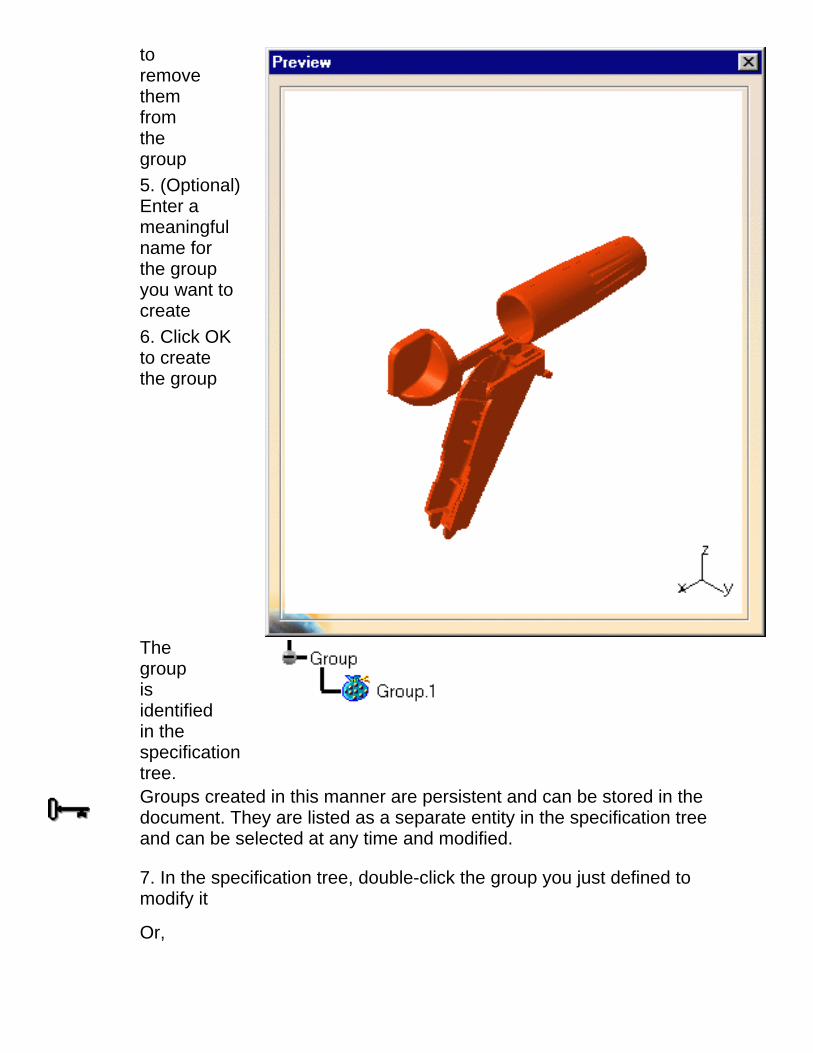
toremovethemfromthegroup5. (Optional)Enter ameaningfulname forthe groupyou want tocreate6. Click OKto createthe group
Thegroupisidentifiedin thespecificationtree.
Groups created in this manner are persistent and can be stored in thedocument. They are listed as a separate entity in the specification treeand can be selected at any time and modified.
7. In the specification tree, double-click the group you just defined tomodify it
Or,
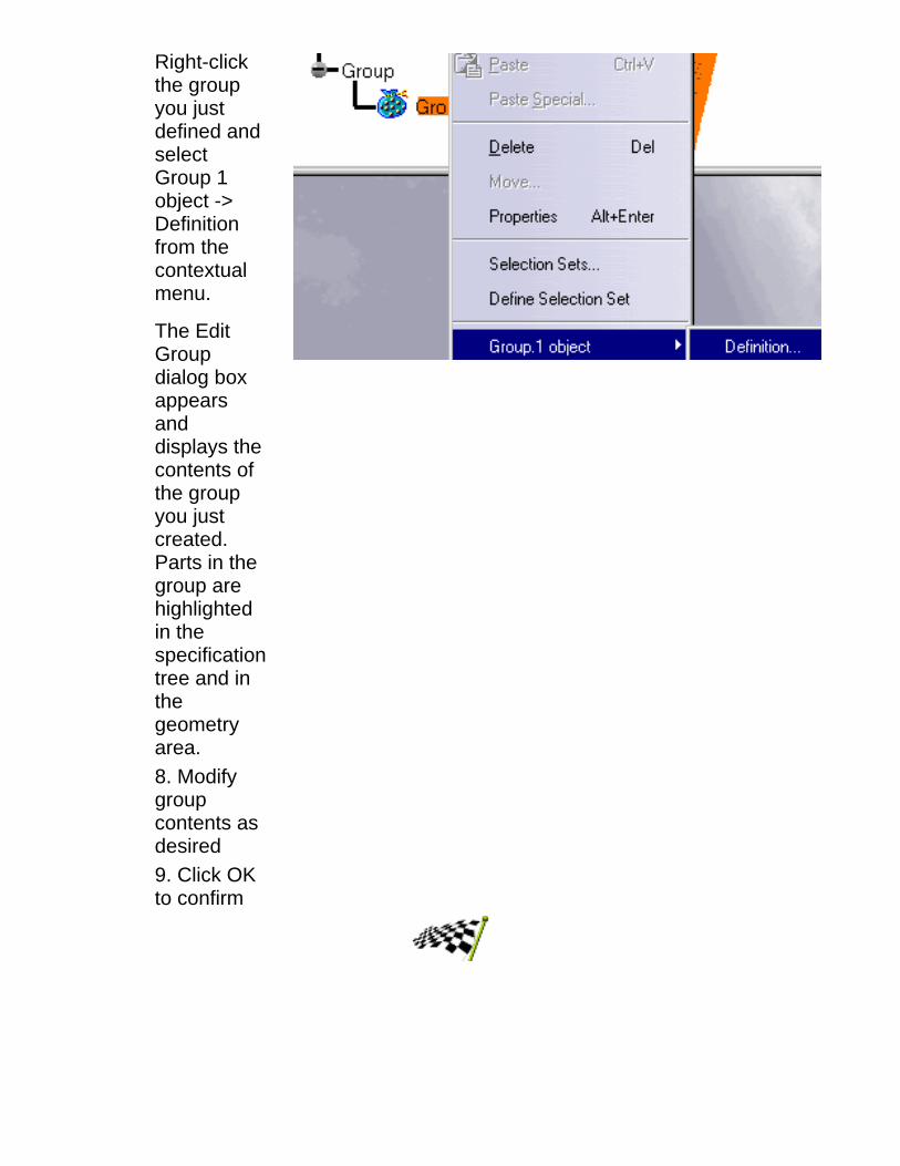
Right-clickthe groupyou justdefined andselectGroup 1object ->Definitionfrom thecontextualmenu.
The EditGroupdialog boxappearsanddisplays thecontents ofthe groupyou justcreated.Parts in thegroup arehighlightedin thespecificationtree and inthegeometryarea.8. Modifygroupcontents asdesired9. Click OKto confirm


Viewing the Current SelectionThe object or objects selected make up the current selection. The list of objects selected can be viewed using the CurrentSelection icon in the DMU Data Navigation toolbar. Making a new selection changes the current selection.For a description of the various selection techniques, please refer to the Infrastructure User's Guide.
Open the .cgr files from the \online\samples\dmunavigator directory.
This task illustrates current selection capabilities
In the geometry area or in the specification tree:1. Select one or more objects
2. Click the Current Selection icon in the DMU Data Navigation toolbar
The Current Selection dialog box identifies all objects selected.

The Current Selection dialog box contains two tabs, letting you visualize the specification tree or 3D view of yourcurrent selection.

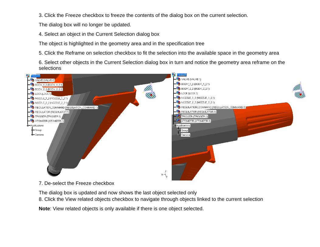
3. Click the Freeze checkbox to freeze the contents of the dialog box on the current selection.
The dialog box will no longer be updated.
4. Select an object in the Current Selection dialog box
The object is highlighted in the geometry area and in the specification tree
5. Click the Reframe on selection checkbox to fit the selection into the available space in the geometry area
6. Select other objects in the Current Selection dialog box in turn and notice the geometry area reframe on theselections
7. De-select the Freeze checkbox
The dialog box is updated and now shows the last object selected only
8. Click the View related objects checkbox to navigate through objects linked to the current selection
Note: View related objects is only available if there is one object selected.

Relationships identified are parents, any children or connected objects and relationships between objects. Products, groups,simulation, shuttles and aec objects are all taken into account.Contextual menu commands are available in the Current Selection dialog box.

Viewing the Cache ContentThe data cache directory (CATCache) defines the disk space used for the saving of conversions of models to cgr files. Oneor more data cache directories can be defined.
If you work with the cache system on, when you re-access the saved model in a subsequent session, the application will usethe entry in the data cache, thereby reducing access time.This task shows you how to view the contents of the data cache.
A DMU Navigator document open
1. Select the Tools -> Cache Content command
The Cache Content dialog box appears listing the contents of the local data cache.
Other information including whether or not the cache system is turned on, the current cache used and themaximum cache size is also given in the dialog box.
2. In the Cache directory drop-down list box, select the cache directory whose contents you want to review
By default, the contents of the local data cache are shown.
3. Click Close when done
To set default data cache settings, see Customizing Data Cache Settings


NavigatingTask Purpose
Default mode for examining objects
Navigate in Beginner's and Advanced Walkmodes
Navigate in Beginner's and Advanced Flymodes
Define viewpoints
Review stored viewpoints
View an object against the ground
View and magnify document contents in aseparate window
Look at objects in a specific direction through auser-defined viewport
Analyze your position in space
Sets different types of light sources to producerealistic lighting effects
Produces depth effects by clipping geometrybetween clipping planes, and creates a foggyeffect

Navigating in Examine ModeNavigating in Examine Mode is the default mode. You can examine yourdocument as you would from the outside by moving around the document'sperimeter, or as you would from within, turning your head to view or movingcloser (zoom in, zoom out) to different objects.
Note: When in beginner's fly mode, click the Examine mode icon in the Viewtoolbar to return to the default navigation mode.
For more information, see Activating Viewing Tools Using the Mouse in theInfrastructure User's Guide.

Navigating in Walk Mode In Walk mode, you can walk forward and backward as well as turn right or left
as you walk along the horizontal view plane you define.
Two walk modes are available:Beginner's modeAdvanced mode for experienced users.
Before using the Walk navigation mode, you must be in a perspective view(View->Render Style->Perspective).
Beginners Walk ModeThis task shows you how to navigate through a document in beginner's walkmode.
Beginner's walk mode commands are single-action commands. Releasing themouse button means you exit the command. You can only move forward inbeginner's walk mode.
Open Platform.model in the Samples/Infrastructure directory.
You need a V4 Integration license to open this sample document.
1. Select View->Navigation Mode->Walk.
The icons used inthe beginner's walkmode appear in theView toolbar:
These commands are also available via View->Modify in the menu bar.
The horizontal indicator to the right helps you keep track of your horizontalview plane.
2. Click the Turn Head icon in the View toolbar then drag (left mousebutton) to define your starting position
3. Release at desired location.
4. Click the Walk icon, then click the left mouse button to begin to walking:
You begin to walk forward in the chosen direction
5. Still holding the left button down, drag to the right or left to change direction.
Dragging to the left lets you view the object as if you had turned your head tothe left; dragging to the right produces the same effect in the opposite direction
6. Bring the cursor back into the orange rectangle to continue walking forwardin the new direction.
7. To modify your speed, click the Accelerate or Decelerate icon oneor more times, then click the Walk icon again followed by the left mouse buttonto pursue your walk.
Note: The size of the arrow in the navigation compass reflects the speed ofyour walk.
8. To return to the default navigation mode, click the Examine mode iconin the View toolbar
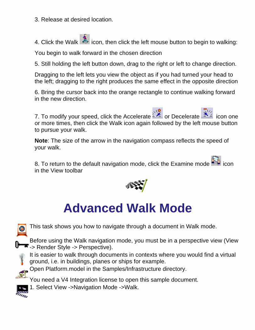
Advanced Walk ModeThis task shows you how to navigate through a document in Walk mode.
Before using the Walk navigation mode, you must be in a perspective view (View-> Render Style -> Perspective).It is easier to walk through documents in contexts where you would find a virtualground, i.e. in buildings, planes or ships for example.Open Platform.model in the Samples/Infrastructure directory.
You need a V4 Integration license to open this sample document.1. Select View ->Navigation Mode ->Walk.

Fine lines that represent the field of vision. When the green point is within theselines, you can see the document in the geometry area
For the walk mode, a horizontal view plane indicator to the right of the compass2. Press and hold down the middle mouse button to define the horizontal viewplane3. Still holding the button down, drag to the left or to the right to determine thedirection in which you wish to walk.In the Walk mode, press and hold down the middle mouse button until you'vefinished navigating.4. When in the direction in which you wish to walk, click the left mouse button tobegin walking.
You begin to walk forward in the chosen direction.
An arrow indicating the direction in which you are walking appears in thenavigation compass.5. Still holding the middle button down, drag left or right to change direction:
Dragging to the left lets you view the object as if you had turned your head to theleft; dragging to the right produces the same effect in the opposite direction.
6. Bring the cursor back into the orange rectangle to continue your walk forwardin the new direction

Pressing the PageUp and PageDown keys modifies your speed. Speed isindicated in the status bar. The size of the arrow in the navigation compassreflects the speed of your walk7. Click the left mouse button again to reverse direction:
You begin to walk backward, away from the target.
Note: The left and right are now defined as if you were walking away from thetarget with the your back towards it.


Navigating in Fly ModeIn Fly mode you can move upward or downward on any horizontal view plane as you moveforward or backward (advanced mode only). The horizontal indicator to the right helps you keeptrack of your horizontal view plane.
Two fly modes are available:Beginner's modeAdvanced mode for experienced users.
Before using the Fly navigation mode, you must be in a perspective view (View->RenderStyle->Perspective).
Beginner's Fly ModeThis task shows you how to navigate through a document in beginner's fly mode.
Note: Beginner's fly mode commands are single-action commands. Releasing the mousebutton means you exit the command. You can only move forward in beginner's fly mode.
1. Click the Fly Mode icon in the View toolbar or select View->NavigationMode->Fly
The four icons used in the beginner's fly mode appear in the View toolbar
These four commands are also available via View -> Modify in the menu bar.

2. Click the Turn Head icon in the View toolbar then drag (left mousebutton) to define your starting position
3. Release at desired location
4. Click the Fly icon, then click the left mouse button to begin to flying:
You begin to fly forward in the chosen direction
5. Still holding the left button down, drag to the right or left to change direction
Dragging to the left lets you view the object as if you had turned your head tothe left; dragging to the right produces the same effect in the opposite direction
6. Bring the cursor back into the orange rectangle to continue flying forward inthe new direction
7. To modify your speed, click the Accelerate or Decelerate icon oneor more times, then click the Fly icon again followed by the left mouse button topursue your fly
Note: The size of the arrow reflects the speed of your fly.
When you collide with a solid object when flying, you will slide along the object's surface,and you will no longer fly through the object, providing a more realistic effect. This featureis also available in Advance Fly mode.
Pressing the Shift key and dragging lets you bank left or right.
Note that the compass and orange rectangle are no longer used.
You can use the option "Gravitational effects when navigating" in theVisualization tab, accessed via the Tools->Options command, to fix the X, Y orZ axis during navigation.While turning in Fly mode, this creates the impressionthat the user viewpoint tilts or banks with respect to the fixed axis, as in a realplane.
8. To return to the default navigation mode, click the Examine mode icon inthe View toolbar

Advanced Fly ModeThis task shows you how to navigate through a document in advanced fly mode.
In advanced fly mode, you can move upward or downward on any horizontal view plane as youmove forward or backward.
1. Click the Fly Mode icon in the View toolbar or select View ->Navigation Mode ->Fly
2. Press and hold down the middle mouse button to define the initial horizontal view plane3. Still holding the button down, drag to the left or to the right to determine the direction inwhich you wish to fly
In the Fly mode, press and hold down the middle mouse button until you've finishednavigating.
4. When in the direction in which you wish to fly, click the left mouse button to begin flying:
You begin to fly forward in the chosen direction.

5. Still holding the middle button down, drag left or right to change direction:
Dragging to the left lets you view the object as if you had turned your head to the left;dragging to the right produces the same effect in the opposite direction.6. Bring the cursor back into the orange rectangle to continue flying forward in the newdirection
Pressing the PageUp and PageDown keys modifies your speed. Speed isindicated in the status bar.
7. Click the left mouse button again to reverse direction:
You begin to fly backwards, away from the target.
Note: When flying backwards, the up and down are reversed.

You can use the option "Gravitational effects when navigating" in theVisualization tab, accessed via the Tools->Options command, to fix the X, Y or Zaxis during navigation.While turning in Fly mode, this creates the impression thatthe user viewpoint tilts or banks with respect to the fixed axis, as in a real plane.
8. To return to the default navigation mode, click the Examine mode icon in theView toolbar

Using the Viewpoint PaletteThe Viewpoint Palette provides an easy and precise way to define your document views. It gives you access to a certain number of viewingtools that will let you fine-tune viewpoints. You can pan and rotate as well as turn your head to view or move closer (zoom in, zoom out) todifferent objects in your document by predetermined increments. You can start from scratch or fine-tune a standard view. Views can then bestored and called up from a list of viewpoints, as well as combined to produce an animation.
To access the Viewpoint Palette, select View -> Viewpoint Palette...The Viewpoint Palette dialog box appears.
Task Purpose
Selecting Standard Views Obtain standard document viewsPanning, Zooming, Rotating & Turning Your Head Pan, zoom, rotate & turn your head by predetermined increments


Selecting Standard ViewsThe Viewpoint Palette offers a certain number of viewing tools that let you define individual document views. You can start fromscratch or fine-tune a standard view. Views can then be stored and called up from a list of viewpoints, as well as combined toproduce an animation.
Open the platform.model document from the \online\samples\dmunavigator directory.
This task shows you how to obtain standard views of your document using the Viewpoint Palette.
1. Select View -> Viewpoint Palette...
The Viewpoint Palette dialog box appears.
2. In the Translate box, click to activate the change view commands
The Translate box now offers a number of standard views (top, back,left, right, front and bottom) you can use to display the document:

3. Click the desired view.
For example, clicking the Top view icon obtains the top view:
The other views are:
Bottom view Left view Right view

Front view Back view
Fine-tune your standard view using other viewing tools (pan, zoom, rotate and turn head) in the Viewpoint Palette.
You can also obtain standard views of your document using the View-> Named Views... command.

Panning, Zooming, Rotating &Turning Your Head
The Viewpoint Palette offers a certain number of viewing tools that let you defineindividual document views. You can start from scratch or fine-tune a standardview. Views can then be stored and called up from a list of viewpoints, as well ascombined to produce an animation.This task shows you how to pan, zoom, rotate and look at objects as if you areturning your head using the Viewpoint Palette.
1. Select View->Viewpoint Palette...
The Viewpoint Palettedialog box appears.
The Translate boxcontains panningand zoomingcommands(default position).
Using thesecommands, youcan move thecurrent documentcontents bypanning theviewpoint as well

as zoom in/out bypredeterminedincrements.
2. Enter a newstep in the spinbox and pressEnter, or scroll toa new value withthe up and downarrows
3. Tryexperimentingwith the pan andzoom commandsuntil you aresatisfied with theviewpointThe Rotate boxcontainscommands lettingyou rotate anobject (defaultposition) and turnyour head to viewthe document.
4. Enter a newrotation step in thespin box andpress Enter, orscroll to a newvalue with the upand down arrows
5. Tryexperimentingwith rotationcommands untilyou are satisfiedwith the viewpoint

6. Click the TurnHead icon tosimulate whathappens whenyou turn yourhead to look at thedocument
7. Enter a newstep in the spinbox and pressEnter, or scroll toa new value withthe up and downarrows
8. Tryexperimentingwith turn headcommands untilyou are satisfiedwith the viewpointYou can also progressively pan, zoom and rotate in the Examinenavigation mode.
Set the viewing distance and angle as well as the eye and targetlocations directly using spin boxes.

Changing ViewsIndividual views are created as you navigate through your design in examine andfly modes. Views are stored and can be reviewed using previous and next iconsin the DMU Viewing toolbar.In fly mode, views are created each time you pause during your fly around.Open the platform.model document from the \online\samples\dmunavigatordirectory.This task shows you how to change views.
1. Navigate in Examine mode (zoom, pan, etc.) to create and save severaldifferent views
2. Click the Previous icon in the DMU Viewing toolbar or select View ->Modify -> Previous View:
The previous view is displayed in the geometry area.3. Click the Previous icon again.
4. Click the Next icon, or select View -> Modify -> Next View:
The next saved view is displayed in the geometry area.


Viewing Objects against the GroundGround lets you visually insert a plane at the ground level of your document, thusenabling you to recognize when your document is viewed the right way up.By default, when you first access a document, the plane parallel or tangent to thebottom point of your document is considered to be the ground. You can,however, change the plane used to identify the ground. For more information,see Customizing the Ground.This task shows you how to show and hide the ground.
1. Select View->Ground, or click the Horizontal Ground icon in theDMU Viewing toolbar.
The ground plane is displayed in the geometry area.
To hide the ground, simply repeat the same step.2. Drag (left mouse button) the ground up or down to a new location, thenrelease the mouse button.
The ground is repositioned as defined.


MagnifyingThis tasks explains how to obtain a magnified view of your document in a separate window.
Open the .cgr files from the \online\samples\dmunavigator directory.
1. Select the View->Magnifier... command or click the Magnifier icon in the DMU Viewing toolbar.
The Magnifier window opens containing a magnified section of your document:
The section magnified is defined by the magnifierviewport which appears over the object in yourdocument:
Note that the magnifier viewport has handles:the "+" symbol lets you move the viewportthe arrows in the corners let you resize theviewport.
2. Point to the + symbol and drag it to move the viewport and magnify another area of the document:

3. Point to one of the arrows and drag it to size the magnified area up and down:
While you drag, the symbol appears
All the viewing and manipulations performed in the document window are also reflected in theMagnifier window. For example, rotate the object to see how the object is also rotated in theMagnifier window:


Looking At ObjectsThis task explains how to look at the document in a specific direction by targeting through auser-defined viewport.
1. Select the View->Modify->Look At command, or click the Look At icon.2. Click (left mouse button) on an object in the document to select it.3. Drag (still holding left mouse button down) slowly to display the viewport.
As you begin to drag, a rectangle with two diagonals appears and continues to grow aslong as you continue to drag. This rectangle represents the viewing window of the futureview.4. Continue dragging to move around, resize and reposition the viewport.
The viewport is then shaped like a pyramid: your eyepoint is located at the vertex of thepyramid. You can resize the viewport by dragging the middle mouse button.
5. Release the button.
You now see what is targeted inside the viewport.
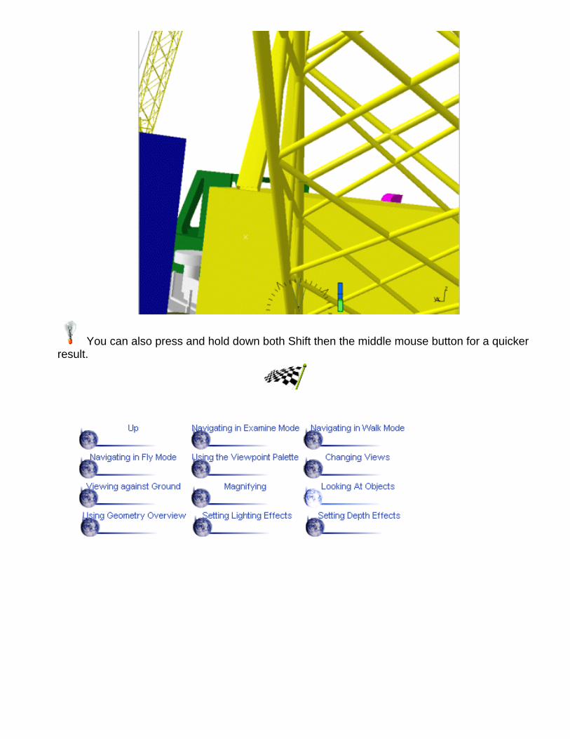
You can also press and hold down both Shift then the middle mouse button for a quickerresult.

Using the Geometry OverviewThis task explains how to use the overview to view the geometry.
1. With geometry visible in the geometry area, select the View->Geometry Overview command.The geometry is displayed in the overview window, but not the specification tree:
2. Point to the Overview window to display the cursor, and drag.
This drags the overview viewport through which you view the geometry. Only that part of thegeometry you see inside the overview viewport will be visible in the document window:

Note that you can resize the overview window itself to see the whole of the viewport.3. Zoom the size of the overview viewport by dragging the handles located at the top right andbottom left corners of the viewport.
While you drag, the cursor changes to: . This lets you zoom the geometry in and out in thedocument window:


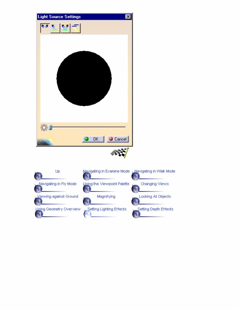
Setting Lighting EffectsThis tasks explains how to vary ambient lighting effects.
1. Select the View->Lighting... command or the Lighting icon in the DMU Viewingtoolbar to display the Light Source Editor dialog box.The default light source settings look like this...
... and produce a lighting effect, for example, like this:

Note that the One Light Source icon is activated by default. The sphereindicates the current lighting direction. The handle on the sphere indicates thedirection from which the light is being projected: by default, the light is comingfrom the top left.You can drag the handle around (using the left mouse button) to change thelighting direction. The new lighting effect is created instantaneously as you dragthe handle.A slider at the bottom of the dialog box lets you adjust light source brightness.2. Drag the handle down and towards the bottom right: the light is now coming from thebottom right:
3. Click the Two Light Source icon to add another light source.

In our example, using two light sources means that the lighting is now too bright.
4. Drag the brightness slider to the left to reduce the brightness.
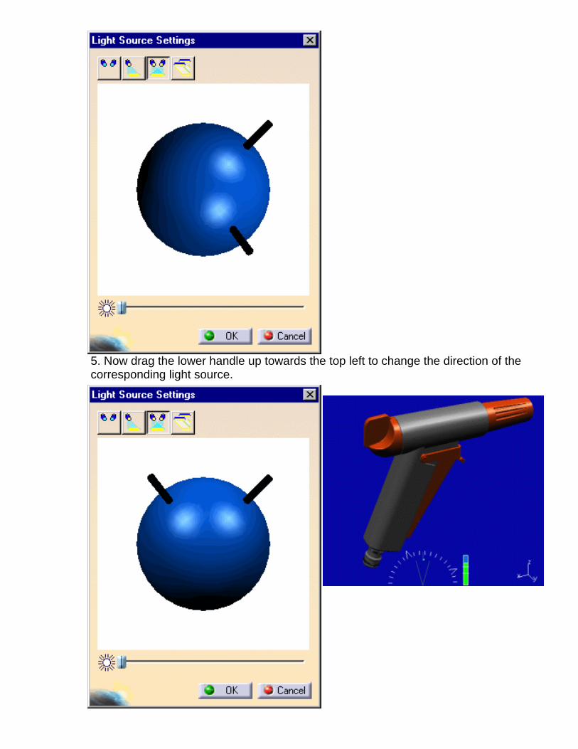
5. Now drag the lower handle up towards the top left to change the direction of thecorresponding light source.
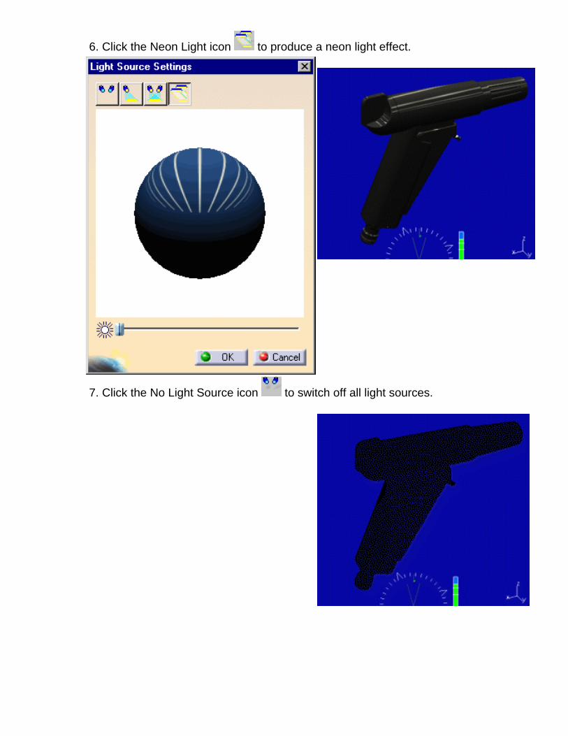
6. Click the Neon Light icon to produce a neon light effect.
7. Click the No Light Source icon to switch off all light sources.

Setting Depth EffectsThis tasks explains how to achieve 3D depth effects, namely, clipping geometry between clippingplanes and creating fog effects.
1. Select the View->Depth Effect... command or the Depth Effects icon in the DMU Viewingtoolbar to display the Depth Effect dialog box.
The orange sphere completely encompasses the objects in your document. The white crossrepresents the center of the objects in the geometry area.
The color of the area behind the orange sphere is the background color of your document.
The vertical lines represent the front (near) and back (far) clipping planes.
By default, depth effects are deactivated: if you zoom in and out, you will see that for themoment the geometry is not clipped.You can keep the Depth Effect dialog box open and continue working with othercommands. You will be able to understand the results obtained by setting depth effects byzooming in and out.2. Set the Near Limit and Far Limit by checking the Fixed checkbox for each option,entering values and pressing Enter in each case.
Note that location of the vertical lines representing the clipping planes has changed.

3. Zoom in progressively to see how the geometry is clipped by the near clipping plane:
The back (far) section of the geometry is clipped. You now only see what is locatedbetween the near and far clipping planes.

4. Zoom out to see all the geometry.5. Click the Foggy option.
The foggy option introduces a foggy effect.
6. Zoom out again.
As you zoom out, the fog effect is increased. The fog gets thicker as you continue to zoom outbeyond the back clipping plane.


AnnotatingTask Purpose
Annotate your document
Create hyperlinks
Jump to hyperlinks
View documents using standard views
Create, modify and delete user-defined views
Annotate views
Visualize object names and point coordinates

Using the 3D MarkerYou can annotate your 3D document. Annotations are attached to the point selected to placethe text.This task explains how to add 3D text.
1. Select Insert -> 3D Annotation from the menu bar or,
click the 3D Annotation icon in the DMU Navigator Tools toolbar.
2. Click an object at the point you want to place the text
Note: You can select the object first.The Annotation Text dialog box appears
2. Enter the desired text in the 3D Text field3. Click OK
The text is added at the desired position. Annotations are attached to the point selected.You can move your document; annotations remain attached to the point at which youplace them.
Note: Text annotations are identified in the specification tree.
A text's drawing properties include its color. You can change the color of text thatyou've already added.

4. Right-click a text you've already added and select Properties from the contextualmenu, or click the text and select Edit -> Properties from the menu bar
Note: Dynamic highlighting as you move your cursor over objects helps you locate them.
The Properties dialog box appears5. Click the Graphic tab to display the graphic properties of the current object6. Make desired changes7. Click OK when done
Checking the Set as default checkbox in the Properties dialog box sets theselected properties as default properties and changes how new annotations willlook when you create them.To delete annotation text, right-click the object and then select Delete from thecontextual menu.

Creating HyperlinksYou can add hyperlinks to your document and then use them to jump to a varietyof locations, for example to a marketing presentation, a Microsoft Excelspreadsheet or a HTML page on the intranet.You can add hyperlinks to models, products and parts as well as to anyconstituent elements.Visualization Mode does not permit selection of individual model elements. Toselect these elements, switch to Design Mode (Edit -> Design Mode)This task explains how to add hyperlinks.
1. Select the Insert->Add Hyperlinks command, or click the Add Hyperlinksicon in the DMU Navigator Tools toolbar2. Select the object you want to represent the hyperlink
Or,1. Select the object you want to represent the hyperlink2. Select the Insert-> Add Hyperlinks command, or click the Add Hyperlinksicon in the DMU Navigator Tools toolbar
The Manage Hyperlink dialog box appears.
3. Enter a name for your hyperlink
Note: This is the name that will appear as a textual cue if the Namecheckbox is set in the Options dialog box. For more information, seeCustomizing DMU Navigator Settings.4. Enter the path to the destination file in the URL field then press Enter
Or,
Click Browse... and select the destination file in the Link to File dialog box

Note: You can add more than one link. Simply enter another path orclick Browse... and select another file. All links created are listed inthe Link to file or URL box.Select a link then click Go to to follow the link to the destination file.Select a link then click Remove to remove existing links.
5. Click OK in the Manage Hyperlink dialog box when satisfiedThe hyperlink is createdand is identified in thespecification tree.
The hyperlink cue isdisplayed on the object inthe geometry area. Bydefault, hyperlink cues aregraphical.
Note: You can change thecolor of the hyperlink cue.To do so, right-click thecue then select Propertiesfrom the contextual menu,or select the cue then Edit-> Properties from themenu bar.Simply right-click the hyperlink cue and select URL object ->AddHyperlinks from the contextual menu to edit the link.

Jumping to HyperlinksThis task explains how to jump to hyperlinks.
There are several ways to jump to hyperlinks: 1. Double click the hyperlink cue, or the desired hyperlink in thespecification tree
Or,
1. Click the Go to Hyperlinks icon in the DMU Data Navigation toolbar2. Select the object with the desired hyperlink, the hyperlink cue or thedesired hyperlink in the specification tree
Or,1. Select the object with the desired hyperlink, the hyperlink cue or thedesired hyperlink in the specification tree2. Click the Go to Hyperlinks icon in the DMU Data Navigation toolbar
Or,
1. Right-click the hyperlink cue and select URL object->Definition...from the contextual menu
If more than one link has been created, the Open Hyperlink dialogbox appears
3. Select the link of interest, then click OKThe file linked is displayed.
Objects with hyperlinks are identified by textual and/or graphical cues.


Using Standard ViewsThis task explains how to use standard views.
1. Select the View->Named Views... command:
The Named Views dialog box appears.
The list provides a number of standard views youcan use to display the document:*front*back*left*right*top*bottom*iso.
2. Double-click the desired view.
For example, double-clicking *front obtains thefront view:
The other views are:


Creating, Modifying and DeletingUser-Defined Views
This task explains how to create, modify and delete user-defined views. Note thatuser-defined views are stored with the document.
1. Select the View->Named Views... command and double-click the desiredview.
You are now ready to customize the view.
2. Adjust the different view parameters (zoom, rotation, etc.) until you arehappy with the result.
3. Click the Add button to add the view to the list.
The default name of the view is Camera 1.

4. Rename the view as required and press Enter.
5. Check the Show Representations checkbox:

You now see a 3D viewpoint representation in the geometry area. The3D representation is a viewport that helps you to define what you wantto see in the view. What you see inside the viewport can then be storedin your view. You can manipulate the 3D representation to defineexactly what you want to see:
zooming, rotating and panning the geometry using the standardtools also affects the 3D representationdragging the corners rotates itdragging any of its sides or any of the corner markers inside therepresentation moves it (the triangular marker always representsthe bottom left corner)dragging the point in the center (the eye position) defines thedirection in which you look at the document.

6. Manipulate the 3D representation to define your view parameters.7. Click the Properties button to access the Camera Properties dialogbox
8. Double-click anywhere on the 3D representation to apply the viewparameters, and click Apply to apply the changes to your view.9. If you want to modify any customized view you already saved, select it,modify the view parameters again, then click the Modify button.You can also delete views by selecting the view from the list andclicking the Delete button.The Reverse button lets you view the object from the reverse angle.


Using the 2D MarkerYou can draw straight lines, freehand lines, circles, arrows and rectangles.You can create complex annotations by combining several objects as well asinclude text in document views.This task explains how to annotate your documents.
To annotate documents, you must be in an active view. Objects drawn areassociated with the active view and will no longer be visible if the view ischanged.
1. Select theView->Named Views...command
The Named Views dialogbox appears.
2. Double-click the desiredview.
The DMU 2D Markertoolbar becomes active.You can now annotateyour view.

3. Click the appropriate icon in the DMU 2D Marker toolbar to drawstraight lines, freehand lines, circles, arrows or rectangles4. Put the cursor where you want to start the object, then click anddrag to draw the object:
To draw a straight line, click at the start of the line and drag from thebeginning to the end of the line.
To draw a freehand line, click at the start of the line and drag thecursor along the path of the line.
To draw a circle or a rectangle, click at the start of the object and dragdiagonally across the area in which you want the object to appear.
To draw an arrow, click at the start of the arrow and drag from thebeginning to the end of the arrow.
5. Click the Text icon to annotate your view with text:
You can now easily move andresize the 2D markers. All youneed to do is drag the greenmanipulators attached to themarker selected.
The Annotation Textdialog box appears6. Enter the desired text inthe text box
7. In the view, click where you want to place the text
The text is added at the desired positionClick Clear to remove the characters you typed in the text box.
An object's drawing properties include color, line type andweight. You can change drawing properties of objects that you'vealready drawn.

8. Select the Select icon to enter the selection mode:9. Right-click an object you've already drawn and select Propertiesfrom the contextual menu, or click the object then select Edit ->Properties from the menu bar
Note: Dynamic highlighting as you move your cursor over objectshelps you locate them.The Properties dialog box appears10. Click the Graphic tab to display the graphic properties of thecurrent object11. Make desired changes:
You can change the color, line type and line weight of the selectedobject12. Click OK when done
You can automatically transform 2D markers in 3D markers selectingAnalyze->Graphic messages from the menu bar.

Checking the Set as default checkbox in the Properties dialogbox sets the selected properties as default properties andchanges how new annotations will look when you create them.To delete all annotations in the current view, select the Delete All
Annotations icon.
You can also delete individual markers by right-clicking theobject and then selecting Delete from the contextual menu.

Using Temporary MarkersYou can visualize the names of objects as well as coordinates of points defined on objectsin your document as you move your cursor over objects.This task explains how to visualize object names and point coordinates
1. Select Analyze -> Graphic Messages -> Name from the menu bar to view objectnames2. Move your cursor over objects in your document:
The name of the object is displayed
3. Re-select Analyze -> Graphic Messages -> Name to de-activate the command4. Select Analyze -> Graphic Messages -> Coordinate from the menu bar to viewpoint coordinates5. Move your cursor over objects in your document:
The coordinates of the point under the cursor are displayed. Dynamic highlightinghelps you identify points of interest.
6. Re-select Analyze -> Graphic Messages -> Coordinate to de-activate thecommand

Using Camera CapabilitiesDMU Navigator provides easy methods to create and move cameras as well as torecord and replay animations.
Task Purpose
Background information on cameras
Create and display cameras
Move cameras to the desired position
Record an animation
Replay an animation

About Cameras
Cameras let you take stills of views or viewpoints in your document. A series ofviews showing different viewpoints in succession can be combined to create ananimation.
Cameras are identified by name in the specification tree and by a symbol
in the geometry area.
A 3D representation helps you locate the viewpoint of interest by showing what thecamera sees through a viewport:
Cameras are moved using the 3D compass.

Creating and Displaying CamerasThis task shows how to create and display cameras.
1. Adjust the view parameters (zoom, rotation, etc.) of the document to define the desired cameralocation
2. Click the Create Camera icon or select Insert->Create Camera from the menu barThe Edit Camera dialog box isdisplayed.
The Preview window, showingwhat the camera sees whencreated, also appears.To changethe default display setting for thiswindow, see Customizing DMUNavigator Settings.3. Identify the camera in the Name field
4. Click Show Graphic Representation to visualize the camera symbol and 3D graphic representationin the geometry area
5. Click OK to create the cameraA camera is created at the current viewpoint. The Preview window is closed.
6. Zoom out and rotate the model to see the 3D representation.

7. Click anywhere in the geometry area to de-select the camera and see the camera symbol.
You can create several cameras at different locations. The DMU Navigator offers you the possibility ofvisualizing the viewpoint of each camera in different windows.
8. Select Window -> Camera Window
All cameras created are listed9. Select the cameras of interest from the list
A new window showing the camera viewpoint is opened for each camera selectedIf you want to organize the opened windows horizontally:10. Select Window -> Tile Horizontally

If you want to organize the opened windows vertically:11. Select Window -> Tile Vertically

If you want to organize the opened windows in a cascading arrangement in which they overlap eachother:12. Select Window -> Cascade

Moving CamerasThis task shows how to move a camera you have just created to the desired position. For this, you will use the 3Dcompass.For information on the 3D compass, see the Infrastructure User's Guide.You defined a Camera
To move a camera, you will attach the 3D compass to the 3D camera representation. If you cannot see the 3Drepresentation, click the camera in the specification tree and select Camera object -> Definition from the contextualmenu, then click the Show Graphic Representation checkbox in the Edit Camera dialog box.
1. Select the camera to be moved in the specification tree:
The 3D representation is shown in the geometry area.2. Attach the 3D compass to the 3D camera representation:
Press and hold down the left mouse button on the red square of the 3D compassDrag the 3D compass to attach it to the camera representation:
Notice that the compass changes appearance as you drag it.
Pointing to a line coming from the eye automatically snaps the compass to the eye and pointing to one of thesides of the viewport snaps the compass to the target.
You can attach the 3D compass to two different positions of the camera representation as shown below: theeye and the target
3. Select Window -> Camera Window and select the camera from the list to open a separate window showingthe camera viewpoint
4. Select Window -> Tile Vertically to organize opened windows vertically

5. Click one of the translation axes of the 3D compass and drag to translate to the desired position

6. Click one of the rotation axes of the 3D compass and drag to rotate to the desired position
7. Continue experimenting until satisfied with the camera position
The camera viewpoint is automatically stored.

Using Generic AnimationDMU Navigator provides to record and replay animations.
Task Purpose
Background information on cameras
Create and display cameras
Move cameras to the desired position
Record an animation
Replay an animation

Recording AnimationsThis task shows how to create an animation using one camera. This is donein two steps:
Defining a simulation.For this, you will use the 3D compass. For more information on the3D compass, see the Infrastructure User's Guide.Creating a film from your simulation.
You defined a Camera.
1. Click the camera inthe specification tree2. Click the Simulation
icon or selectInsert->Simulationfrom the menu bar
The EditSimulationdialog box andthe Previewwindow showingthe objectmanipulated (inour case, thecamera)appear.
To change thedefault displaysetting for thePreviewwindow, seeCustomizingDMU NavigatorSettings.3. Close the Previewwindow
4. Click the Insertswitch and record the

shots.Remember the initial position is automatically recorded.
The camera viewpoint is stored in the Simulation object eachtime you click Insert. You can, in this way, record a series ofviewpoints which when combined and compiled create youranimation.5. Using the 3D compass, move the camera to a new location
By default, the 3D compass snaps to the eye when you clickedthe Simulation icon if it wasn't attached before.
6. Click Insert and record the desired shot7. Move the camera as often as necessary, clicking Insert to recordshots
You may find it useful to open the camera window (Window->CameraWindow) and tile the two windows. This will allow you to see the cameraviewpoint better as you move the camera.
8. Use the VCR buttons to position the camera in its originallocation and replay the recorded camera positions9. Click OK to save the simulation.
Note: No track is displayed when defining a simulation forcameras.
You are now ready to create a film. This is done by compilingyour simulation.10. Select the Simulation object in the specification tree
11. Click the Compile Simulation icon
The Compile Simulation dialog box appears
12. Enter a meaningful name for your film if desired
13. Activate the Number of steps drop-down list box and selectthe number of steps you want to break down each shot into

14. Click OK to compile the simulation and create a film:
You can see the results in the geometry area as the simulation isbeing compiled.For more information on Simulation and Compile Simulationcapabilities, see the Fitting Simulator User's Guide.Use Simulation in this way to produce an animated inspection ofyour design.
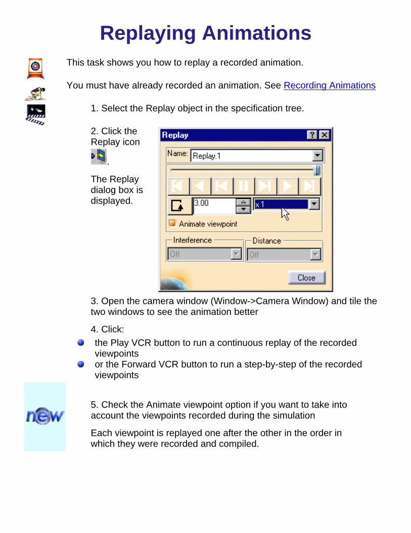
Replaying AnimationsThis task shows you how to replay a recorded animation.
You must have already recorded an animation. See Recording Animations
1. Select the Replay object in the specification tree.
2. Click theReplay icon
.
The Replaydialog box isdisplayed.
3. Open the camera window (Window->Camera Window) and tile thetwo windows to see the animation better
4. Click:the Play VCR button to run a continuous replay of the recordedviewpointsor the Forward VCR button to run a step-by-step of the recordedviewpoints
5. Check the Animate viewpoint option if you want to take intoaccount the viewpoints recorded during the simulation
Each viewpoint is replayed one after the other in the order inwhich they were recorded and compiled.

5. Adjust the sampling step:
Leaving the value at x1 replays the film in the number of stepsdefined when compiling the simulation. Increasing the valuespeeds up the animation, for example, setting the sampling stepto x2 will replay the film at every second step.You can choose one of the loop modes to re-run the animation ina continuous way (either in one direction only or in one directionthen the other).
For more information on Replay capabilities, see the FittingSimulator User's Guide.

Generating an Animation FileThis task shows you how to generate an animation file.
You must have already recorded an animation. See Recording Animations
1. ClicktheCompileSimulation
icon .
TheCompileSimulationdialog boxdisplays
2. Makesure theGenerateananimationfile optionisactivated.
3.(Optional)Enter ameaningfulname fortheanimationfile youwant tocreate.
4.Activatethe Timestepdrop-down

list boxandselect thetime step.
5.ClickFilenametostoreyouranimation.The SaveAs dialogboxdisplays6. ClickSave.
Theanimationfile iscreatedand savedIn AVIMicrosoftformat.
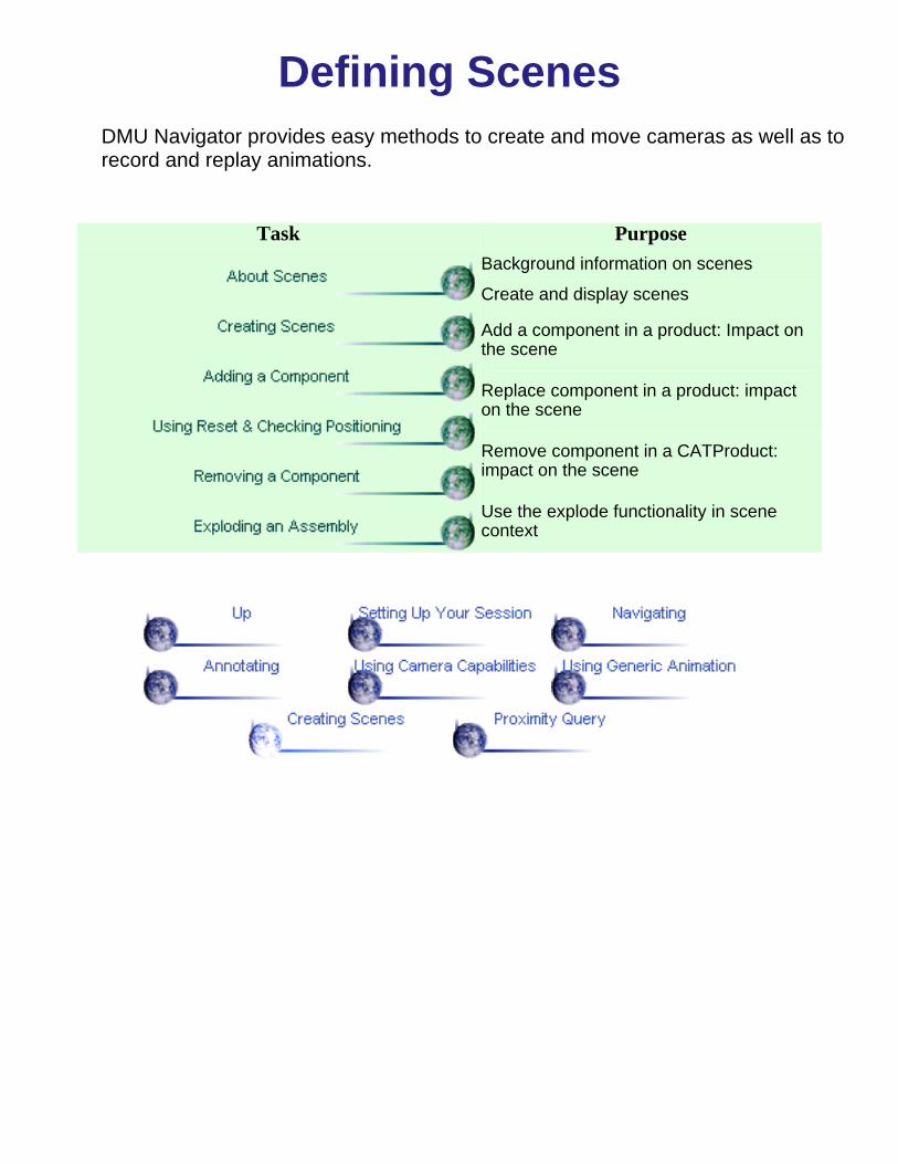
Defining ScenesDMU Navigator provides easy methods to create and move cameras as well as torecord and replay animations.
Task Purpose
Background information on scenes
Create and display scenes
Add a component in a product: Impact onthe scene
Replace component in a product: impacton the scene
Remove component in a CATProduct:impact on the scene
Use the explode functionality in scenecontext

About Scenes
The Scene capability lets you control the position and orientation of eachcomponent of an assembly. You can easily rotate a component and set differentpositions orientations in an instance.
Scenes are identified by name in the specification tree and by a graphicalrepresentation in the geometry area.The following operations are not allowed in a Scene context:
addremovereplacecutdeletepaste

Creating ScenesThis task shows you how to create scenes.
Insert sample files \online\samples\dmunavigator\ GARDENA*.cgr.
1. Click the Create Scene icon .
The Edit Scene dialog box and a scene representation inthe window display
2. click Ok to end the scene creation.You are now in a scene window:
The background window turns to green.Scene 1 is identified in the specification tree.

3. Perform the required modifications. For instance modify the viewpoint.graphical attributesshow-no show
Within a scene, click the Reset selected products icon to reposition the components asthey were in the initial product. Note that the color attributes, show-no show specification arenot taken into account when using the Reset selected products icon.
4. Click the Exit From Scene icon to swap to the initial window.
The scene is updated.

5. Double-click Scene 1 either in the specification tree or in the geometry area toswap to the scene window.6. Create as many scenes as needed.
Clicking off View -> Scene Specification Visible in the menu bar removes the scenerepresentation and lets you use the entire screen for the product. You can also use the F3 keyto toggle more quickly.

Adding a ComponentThis task shows you how to add a component in a Product.
Insert sample files \online\samples\dmunavigator\*.cgr except NOZZLE_1_2.cgr and NOZZLE_2_2.cgr.
1. Click the Create Scene icon .
The Edit Scene dialog box and a scene representation in the window appear.

2. Click OK to end the scene creation.
You are now in a scene window:the background window turns to green.Scene 1 is identified in the specification tree.

4. Click the Exit From Scene icon to swap to the initial window.The scene is created and its representation appears in the left corner of the main window
5. Now add the NOZZLE, for this:Select Product.1 in the specification tree and select Insert->existing component...Shift-select NOZZLE_1_2.cgr and NOZZLE_2_2.cgr
6. The added component (NOZZLE) is identified in the specification tree and added in the geometry area.

Back in the scene window:The corresponding component is automatically added and appears in the specification treethe shape representation is deactivated therefore the scene visualization is unchanged.
Clicking the Exit From Scene icon updates the scene.


Using the Reset Selected ProductsThis task shows you how to use the Reset Selected ProductsPlease refer to Creating ScenesInsert sample files \online\samples\dmunavigator\*.cgr.You created Scene.1.
1. Double-click the scene representation to enter the scene.
In this scene you moved the certain components.

2. Select Tools->Checking Positioning... from the menu bar to find out the itemsyou moved.
The moved items are highlighted in the specification tree.

3. Click the Reset selected products icon and exit the scene.0The items are repositioned in the scene as they were in the initial product.


Removing a ComponentThis task shows you how to view the contents of the data cache.
Insert sample files \online\samples\dmunavigator\ GARDENA*.model.You created a first Scene.
1. Remove the REGULATION_COMMAND for instance.
2. Scene 1 is updated.

This scenario is also valid when replacing a component. The scene is automatically synchronized.

Using Explode in a SceneThe Explode function is available in the assembly workbench and can be used in scene context. You can easily create a scene and explode the assembly without changinganything in the original assembly
This task shows you how to manage an exploded view in scene context
Insert sample files \online\samples\dmunavigator\ GARDENA*.cgr.
1. Click the Create Scene icon .
The Edit Scene dialog box and a scene representation in the window display:
2. Click Ok to end the scene creation.
3. 3. Select Product.1and click the Explode icon .

4. Click Apply.This is what you obtain:
5. Click the Exit From Scene icon to swap to the initial window.

For more details about the explode capacity, please refer to the DMU Fitting Simulator User's Guide.

Proximity QueryTasks
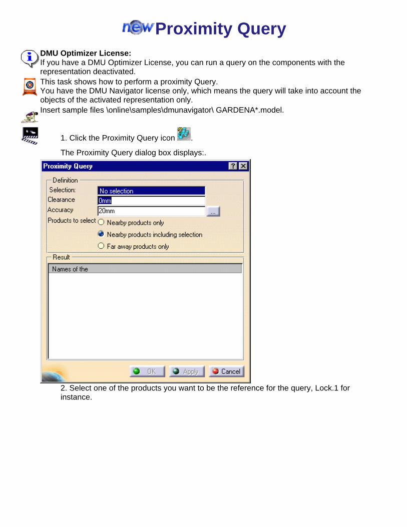
Proximity QueryDMU Optimizer License:If you have a DMU Optimizer License, you can run a query on the components with therepresentation deactivated.This task shows how to perform a proximity Query.You have the DMU Navigator license only, which means the query will take into account theobjects of the activated representation only.Insert sample files \online\samples\dmunavigator\ GARDENA*.model.
1. Click the Proximity Query icon .
The Proximity Query dialog box displays:.
2. Select one of the products you want to be the reference for the query, Lock.1 forinstance.

3. Set the accuracy by entering a value, 3mm for example.4. Check the Far awayproducts only option.5. Click Apply.The result displays in the Result field
6. Click OK when done.The products found are highlighted both in the specification tree and geometry area:

7. Hide the products found.Now you can work with a simplified assembly.

You can combine the Proximity Query command with other DMU commands for exampleComparing Products (DMU Space Analysis toolbar). Note that if you have only the DMU Navigatorlicense, the query only takes into account the products with an activated representation.

Proximity Query with DMU Optimizer licenseThis task shows how to run a proximity Query based on components inserted without representation.You load the product structure only.Insert sample files \online\samples\dmunavigator\ PLATFORM*.model.
Make sure the representation is de activated before inserting your model files.
1. Deactivate the representationFor this:
a. Select Tools->Options from the menubar.The Options dialog box displays.
b. Click Product in the left-hand box.c. Click the Product Structure tab.d. In the Representation field, check theDo not activate default shape on openoptione. click Ok to confirm your operation.
For more details please refer in Customizing Settings to Product Structure Only
2. Click the Proximity Query icon .
The Proximity Query dialog box appears:.
2. Select one of the products you want to be the reference for the query,PLATFORM_10(PLATFORM_10.1) for instance.

3. Set the Clearance by entering a value. In our example, we will keep the default value of 0mm.4. Set the Accuracy by entering,1000mm for example.5. Check the Nearby products including selection option.6. Click Apply.The result displays in the Result field.

7. Click OK when done.
The products found are highlighted in the specification tree.8. Specify the shape representation of the items for this:
Right-click the highlighted items in the specification treeSelect RepresentationSelect Activate nodes
This is what you obtain:Now you can work with a simplified assembly.

You can combine the Proximity Query command with other DMU commands for example Comparing Products (DMU Space Analysis toolbar). Note that if you have only the DMU Navigator license, the query only takes intoaccount the products with an activated representation.

Workbench DescriptionThe DMU Navigator Version 5 application window looks like this:
Click the hotspots to see related documentation.
DMU Navigator Menu Bar
DMU Navigator Tools Toolbar
DMU Viewing Toolbar
View Toolbar
DMU 2D Marker Toolbar
DMU Data Navigation Toolbar
DMU Generic Animation Toolbar

DMU Navigator Menu BarThis section presents the menu bar tools and commands dedicated to the DMU Navigatorworkbench
Start File Edit View Insert Tools Analyze Windows Help
ViewFor... See...
Modify -> Previous View Changing Views
Modify -> Next View Changing Views
Modify -> Look At Looking At Objects
Viewpoint Palette... Using the Viewpoint Palette
Named Views... Using Standard Views andCreating, Modifying and Deleting User-DefinedViews
Navigation Mode ->Examine
Navigating in Examine Mode
Navigation Mode -> Fly Navigating in Fly Mode
Lighting... Setting Lighting Effects
Depth Effect... Setting Depth Effects
Ground Viewing Objects against the Ground
Magnifier... Magnifying
InsertFor... See...
Create Camera Using Camera Capabilities

Add Hyperlinks Creating Hyperlinks
3D Annotation Using the 3D Marker
Group Defining Groups of Products
Simulation Recording a Camera Animation
NewComponent
Assembly User's Guide
New CDM Component Integration User's Guide
New Part... Assembly User's Guide
ExistingComponent...
Inserting Components
ToolsFor... See...
Options Customizing DMU Navigator Settings
Customizing Data Cache Settings
Loading the Product Structure Only
Customizing the Reference Plane
CacheContent Viewing the Cache Content
AnalyzeFor... See...
GraphicMessages
Using Temporary Markers
Space Map Using the Space Map

DMU Navigator Tools Toolbar
See Creating a Camera
See Creating HyperlinksSee Using the 3D Marker
See Defining Groups of Products
See Creating Scenes

DMU Viewing Toolbar
See Looking At Objects
See Changing Views
See Changing Views
See MagnifyingSee Setting Depth Effects
See Viewing Objects against the Ground
See Setting Lighting Effects

View Toolbar
See Navigating in Fly ModeSee Navigating in Examine Mode

DMU 2D Marker ToolbarThe DMU 2D Marker toolbar contains the following tools:
For all 2D Marker tools, see Using the 2D Marker

DMU Data Navigation Toolbar
See Selecting Using the Search... Command in the Infrastructure User'sGuideSee Viewing the Current Selection
See Jumping to Hyperlinks

DMU Generic Animation Toolbar
See Recording Animations
See Recording AnimationsSee Replaying Animations

Customizing SettingsBefore you start your first working session, you can customize the way you work to suit your habits.You can, for example, customize how the data cache is managed. This is done using Tools -> Optionsfrom the menu bar.
This type of customization is stored in permanent setting files. Settings will not be lost if you exit yoursession.
Task Purpose
Change the appearance of the hyperlink cue
Customize cache management settings
Load the product structure without associated 3D representations
Specify the reference plane used for ground and navigating
Change the Import parameters

Customizing DMU Navigator SettingsThis task explains how to customize DMU Navigator settings.
A DMU Navigator document
1. Select the Tools->Options... command.
The Options dialog box appears
2. Click Product in the left-hand box3. Click the DMU Navigator tab
The DMU Navigator tab lets you customize:The appearance of the hyperlink cueMeasurement display: number of decimal places after the decimal point for length, angle, areaand volume measurementsAutomatic display of preview windows
4. Set Hyperlink Representation to Symbol, Name or both:
By default, all hyperlink cues are graphical ( ).If you click the Name checkbox, all hyperlink cues will be textual. The name you give the link in theManage Hyperlink dialog box when you create it will appear.
You can add hyperlinks to your document and then use them to jump to a variety of locations, forexample, to a marketing presentation, a Microsoft Excel spreadsheet or a HTML page on the intranet.
5. To set the default measurement display, enter the number of decimal places you want to seedisplayed after the decimal point; for example for length measurements, enter 4 to display 20.4235
6. Repeat the above for angle, area and volume measurements
7. Click preview checkboxes as appropriate to change the automatic display setting of preview windowswhen creating cameras, manipulating objects, etc.
By default, preview windows are automatically displayed.
8. Click OK in the dialog box when done.

Customizing Data Cache SettingsThe data cache directory (CATCache) defines the disk space used for the saving of conversions of models to cgrfiles. One or more data cache directories can be defined.
If you work with the cache system on, when you re-access the saved model in a subsequent session, theapplication will use the entry in the data cache, thereby reducing access time.This task explains how to customize data cache settings
A DMU Navigator document
1. Select the Tools->Options... command.
The Options dialog box appears
2. Click Product in the left-hand box3. Click the Cache Management tab

4. Turn the cache activation mode on or off:Work with the cache system box checked: the data cache is active and any cgr files in the directoriescurrently listed in the cache location will be accessed. The local data cache is browsed first before thereleased data cache locations.The first time models are inserted, they will be converted to cgr files and saved in the data cache.
By default, the activation mode is set to on.Work with the cache system box unchecked: the data cache is inactive. Cgr files in the data cache will notbe accessed and models will be converted each time they are inserted.
5. (Optional) Enter the paths identifying the cache locations:
Browse buttons let you locate the file you want. The user can enter the path to his own local cachelocation as well as one or more paths to released cache locations.The default directory is the user's home directory under UNIX and the USERPROFILE directory underWindows.
6. (Optional) Set the maximum size for the cache
The default size is 10 MB.
7. (Optional) Set the Check timestamp option:
The Check timestamp option, if clicked, checks the model's timestamp and if different from thetimestamp of cgr files in the data cache, converts the model to cgr files. If timestamps are the same, noconversion is done and cgr files in the data cache are loaded.Turning this option off means that no check is run and cgr files in the data cache are systematicallyloaded.8. Note that you need to exit and restart to see the effects of customization, so click OK to confirm.

Loading the Product Structure OnlyYou can load the product structure only without associated 3D representationsand then specify which 3D representations to insert.
This task explains how to load the product structure without the associated 3Drepresentations.
An empty DMU Navigator document
1. Select the Tools->Options... command.
The Options dialog box appears
2. Click Product in the left-hand box3. Click the ProductStructure tab
4. Click No representation activated to load the product structure only5. Click OK to confirm.
When inserting components, only the product structure will beloaded. You can then specify which 3D representations you want tobe activated by right-clicking the desired item in the specification treeand selecting Representation -> Activate from the contextual menu.


Customizing the GroundA reference plane serves to locate the ground when navigating.
You can fix the X, Y or Z axis (axis perpendicular to the ground) during navigation.While turning in Fly mode, thiscreates the impression that the user viewpoint tilts or banks with respect to the fixed axis, as in a real plane.This task explains how to customize the ground.
A DMU Navigator document
1. Select the Tools->Options... command.
The Options dialog box appears2. Click the Visualization tab
3. Click the Gravitational effects during navigation checkbox to activate this option4. Click X, Y or Z to fix the axis perpendicular to the reference plane. While turning in Fly mode, this creates the impression that the user viewpoint tilts or banks with respect to thefixed axis, as in a real plane.
Note: The z-axis is the default axis. The ground corresponds to the xy reference plane.5. Click OK to confirm.


Customizing External Format ImportYou can now easily import a CAD part which is not directly supported by DMU Navigator.
DMU Navigator runs a background converter that will output one of the following formats:cgr;pdb (Deneb part)vrmlstl.
The CAD part files you want to import must have the .prt extension (.asm for Assemblies).
You can import various types of CAD Parts into a CATProduct. For more details please referto the DMU Navigator User's Guide.This task explains how to customize the import settings.
You imported a CAD Part through the Insert ->Existing Component command.
1. Select the Tools->Options... command.
The Options dialog box appears2. Click Product in the left-hand box .3. Click the External Formats tab.
The corresponding Part Import box, (depending on the configuration) displays below theStandard Formats Import box.

4. Modify the settings as desired. 5. Click OK to confirm your operation.

Glossary3D
3D representation Used to define your document viewpoints when usingnamed views and camera capabilities.
Ddata cache The area of storage used for the saving of conversions of models to cgr files.
Eexamine The default navigation mode. Let's you view your document from the outside by moving around the document's perimeter, or from within,
turning your head to view or moving closer (zoom in, zoom out) to different objects.eye Defines the observer's position. See 3D representation.
Ffly A navigation mode that lets you move upward or downward on any horizontal view plane as you move forward or backward through your
document.
Note: In beginner's mode, you cannot move backward.
P

product
In DMU wokbenches, subset or constituent part of a CATProduct document that can be of the following type:cgr (*.cgr)V4 model (*.model)CATpart (*.CATpart)CATproduct (*.CATproduct)V4 session (*.session)VRML 1.0.obj (*.obj)byu (*.byu)igespdb (*.pdb)stl (ASCII and binary) (*.stl)
Ffly A navigation mode that lets you move upward or downward on any horizontal view plane as you move forward or backward through your
document.
Note: In beginner's mode, you cannot move backward.target Defines the point of the document at which the eye is looking. See 3D representation.
UURL Uniform Resource Locator. A text used for identifying and addressing an item in a computer network.
Vviewing distance The distance between the eye and the target.
viewport Defines what you see in a document view. You can manipulate the 3D representation to define exactly what you want to see. See 3Drepresentation.

Index
Numerics2D objects
changing properties 3D Annotation command 3D marker 3D representation 3D text
changing color of
AAdd Hyperlinks command adding
2D text 3D text arrows circles coordinates hyperlinks lines object names rectangles temporary markers
analyzing your position in space animation
recording replaying
annotatingusing the 2D marker using the 3D marker

Bback view beginner's fly mode bottom view
Ccameras
creating moving using in animations
clipping plane , commands
3D Annotation Add Hyperlinks Compile Simulation Create Camera Current Selection Depth Effect... Existing Component... Fly Go to Hyperlinks Graphic Messages Group... Horizontal Ground Lighting... Look At Magnifier Named Views... , , New... Next View
Previous View Replay Shuttle ,

Simulation Space Map Viewpoint Palette... components
inserting contextual menu
align attach axis editor follow free target
Create Camera commandcreating
cameras groups of products hypertext links new documents user-defined views
current selectionviewing
Current Selection command
Ddata cache
viewing content defining
groups of products deleting
user-defined views

Depth Effect... command depth effects
Far Limit foggy Near Limit
DMU 2D marker toolbar DMU Management toolbar DMU Visualization toolbar documents
creating new
Eexamine mode Existing Component... command
FFar Limit Fly command fly mode
beginner's fly mode advanced fly mode
front view
GGo to Hyperlinks command Graphic Messages command Group... command ground
customizing groups
defining

HHorizontal Ground command hyperlinks
creating jumping to
Iinserting
components isometric view
Lleft view lighting effects
neon light one light source switching off light sources two light sources
Lighting... command Look At command Look At icon looking at through viewport
MMagnifier command manipulator
moving markers
using temporary markers using the 2D marker using the 3D marker

modifyinguser-defined views
movingcameras
NNamed Views... command , , navigating
changing views examine mode fly mode magnified views viewing objects against the ground
Near Limit New... command Next View command
PPrevious View command products
defining groups of product structure properties
2D object 3D text
Rrecording animations replaying animations right view

Ssettingdepth effects lighting effects shuttle
moving Space Map command standard views
back bottom front isometric left right top
Ttemporary markers top view
Uuser-defined views
show representations
Vviewing
changing views current selection data cache content looking at magnifying

objects against the ground panning rotating standard views turn headuser-defined views using camera capabilities using viewpoint palette zooming
viewpoint palette Viewpoint Palette... command