dsfm-vg dsf, dsfm, dsfi, dsfn, · 2019-09-20 · holes. apply liberal bead of 2-part epoxy between...
TRANSCRIPT
2
DS
F, D
SF
M, D
SF
I, DS
FN
,
DS
FM
-VG
OP
EN
FIS
H S
ER
VIC
E C
AS
E
INS
TA
LL
AT
ION
& O
PE
RA
TIO
N G
UID
E
/CHINO
DSF, DSFI, DSFM, DSFNOPEN FISH SERVICE CASE REV. 0317
Installation
& Operation
Manual

2
/CHINOA publication of HUSSMANN® Chino
13770 Ramona Avenue • Chino, California 91710
(909) 628-8942 FAX
(909) 590-4910
(800) 395-9229
Keep this booklet with the case at all times for future reference.
General Instructions
Table of ContentsGeneral Instructions........................................................................... 2Cut and Plan Views ............................................................................ 3Installation ........................................................................................... 4
Location .................................................................................................................. 4Uncrating the Stand ................................................................................................ 4Exterior Loading ..................................................................................................... 4Setting and Joining ................................................................................................. 4Leveling .................................................................................................................. 4Corner Wedges....................................................................................................... 4Joint Trim ................................................................................................................ 4Scale Stand Installation Instructions ....................................................................... 5Wrapping Boards Installation Instructions .............................................................. 6Bumper Installation Instructions ............................................................................. 8DSF End Wing Assembly Instructions .................................................................... 9Parts and Components List .................................................................................... 9Channel Weldment Assembly ............................................................................... 12Place Hinges ........................................................................................................ 13End Wing Attachment ........................................................................................... 14Plex Post Installation ............................................................................................ 14Bumper Installation ............................................................................................... 15Operation Notes ................................................................................................... 15Critical Dimensions and Measurements ............................................................... 16DSF Hardware Notes ........................................................................................... 17Installing and Adjusting DSF Glass ...................................................................... 17Glass Stop and End Wing Final Position Notes ................................................... 18
Plumbing ........................................................................................... 24Waste Outlet and P-TRAP .................................................................................... 24Installing Condensate Drain ................................................................................. 24
Humidifi cation ................................................................................... 25General Description .............................................................................................. 25Humidifi cation System Hookups ........................................................................... 25Start-up ................................................................................................................. 25Maintenance ......................................................................................................... 25
Manifold Flush System .................................................................... 26General Description .............................................................................................. 26Basic System Operation: ...................................................................................... 26Start Up: ............................................................................................................... 26Manual Flush System ........................................................................................... 26
Refrigeration ..................................................................................... 27Refrigerant Type ................................................................................................... 27Piping .................................................................................................................... 27Refrigeration Lines ............................................................................................... 27Control Settings .................................................................................................... 27Access to TX Valves and Drain Lines ................................................................... 27Electronic Expansion Valve (Optional).................................................................. 27Thermostatic Expansion Valve Location ............................................................... 27Measuring the Operating Superheat .................................................................... 27T-STAT Location ................................................................................................... 27
Electrical............................................................................................ 33Wiring Color Code ................................................................................................ 33Electrical Circuit Identifi cation ............................................................................... 33Electrical Service Receptacles (When Applicable) ............................................... 33Field Wiring and Serial Plate Amperage ............................................................... 33Ballast Location .................................................................................................... 33Wiring Halogen Lights .......................................................................................... 33Ashrae Color Code ............................................................................................... 34
User Information ............................................................................... 34Stocking ................................................................................................................ 34Important Steps .................................................................................................... 34Case Cleaning ...................................................................................................... 35Cleaning Glass and Mirrors .................................................................................. 35Non-glare Glass .................................................................................................... 35Plexiglass and Acrylic Care .................................................................................. 35Cleaning ............................................................................................................... 35Antistatic Coatings ................................................................................................ 35
Maintenance ...................................................................................... 36
This Booklet Contains Information on:
DSF, DSFI, DSFM, DSFN, DSFM-VG Straight-glass
refrigerated service Open Fish mechandiser
Shipping Damage
All equipment should be thoroughly examined for shipping
damage before and during unloading.
This equipment has been carefully inspected at our factory
and the carrier has assumed responsibility for safe arrival.
If damaged, either apparent or concealed, claim must be
made to the carrier.
Apparent Loss or Damage
If there is an obvious loss or damage, it must be noted on
the freight bill or express receipt and signed by the carrier’s
agent; otherwise, carrier may refuse claim. The carrier will
supply necessary claim forms.
Concealed Loss or Damage
When loss or damage is not apparent until after equipment
is uncrated, a claim for concealed damage is made. Make
request in writing to carrier for inspection within 15 days,
and retain all packaging. The carrier will supply inspection
report and required claim forms.
Shortages
Check your shipment for any possible shortages of material. If
a shortage should exist and is found to be the responsibility of
Hussmann Chino, notify Hussmann Chino. If such a shortage
involves the carrier, notify the carrier immediately, and
request an inspection. Hussmann Chino will acknowledge
shortages within ten days from receipt of equipment.
Hussmann Chino Product Control
The serial number and shipping date of all equipment
has been recorded in Hussmann’s fi les for warranty and
replacement part purposes. All correspondence pertaining
to warranty or parts ordering must include the serial number
of each piece of equipment involved, in order to provide
the customer with the correct parts.
This equipment is to be installed
to comply with the applicable
NEC, Federal, State , and Local
Plumbing and Construction
Code ha ving jurisdiction.ATTENTIONINSTALLER
Replacing Fluorescent Lamps .............................................................................. 36Evaporator Fans ................................................................................................... 36Copper Coils ......................................................................................................... 36Tips and Troubleshooting ..................................................................................... 36Stainless Steel Cleaning and Care ....................................................................... 36
Electrical Wiring Diagrams .............................................................. 37Wiring Diagrams ............................................................................... 38Appendices ....................................................................................... 44
Appendix A. - Temperature Guidelines - Refrigerated .......................................... 44Appendix B. - Application Recommendations - Refrigerated ................................ 44Appendix C. - Field Recommendations - Refrigerated ......................................... 44Appendix D. - Recommendations to User - Refrigerated ..................................... 45
3
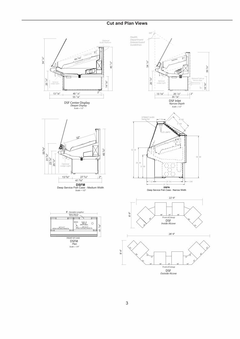
Cut and Plan Views
DSFOutside Alcove
48" 48"
48"
24"
24"
24"
48"
28'-9"
8'-
4"
Fr ont of Lineup
19"
34"34"
34" 34"
19"
19"
19"
DSFInside Alcove
48" 48"
48"
24"
24"
24"
48"
22'-9"
8'-
9"
Fr ont of Lineup
DSF Center DisplayDeeper Display
Scale = 1/2"
40 1/4"
55 7/8"
13 5/8"2"
5"
8"
OptionalScale Platform
OptionalLedge Lights
54
1/4
"
45
1/2
"
14
5/8
"
45 3 /4"
Optional P an Depth
Load Line
20
1/4
"
load line
DSF InletNarrow Depth
Scale = 1/2"
Optional Fold-upService Step
8"
5"
14
5/8
"3
93/4
"
20 1/4"35 7/8"
20
1/4
"
54
1/4
"
13 5/8" 2"
OptionalLedge Light
60"
HealthDepartmentSneeze GuardGuidelines
55
5/8
"
31
3/4
"
20
1/2
"
23
1/4
"
13 5/8"
41 5/8"
45
1/2
"
32"
DSFMDeep Service Fish Case - Medium Width
Scale = 1/2"
OptionalLedge Light
27 3/4" 2"
41
5/8
"
8' (Variable Lengths)
DSFMPlan
Scale = 1/4"
Water Valve &Access Panel
FRONT OF CASE
DRAIN ELEC. &MECH.
DROP AREA
44" X 21"OPEN FOR MECHANICAL
44" X 21"OPEN FOR MECHANICAL
21 5/8
39 3/4
53 1/8
35 7/8
7 1/2 26 3/4 1 5/8
28 3/4
STRAIGHT GLASSSwing Out
LED LIGHTS
7 7/8
17 5/8
18 5/8
24 1/25 3/8
DSFN
Deep Service Fish Case - Narrow Width
4
Installation
LocationThe refrigerated merchandisers have been designed for use only in air conditioned stores where temperature and humidity are maintained at or below 75°F and 55% relative humidity. DO NOT allow air conditioning, electric fans, ovens, open doors or windows (etc.) to create air currents around the merchandiser, as this will impair its correct operation.
Product temperature should always be maintained at a constant and proper temperature. This means that from the time the product is received, through storage, preparation and display, the temperature of the product must be controlled to maximize life of the product.
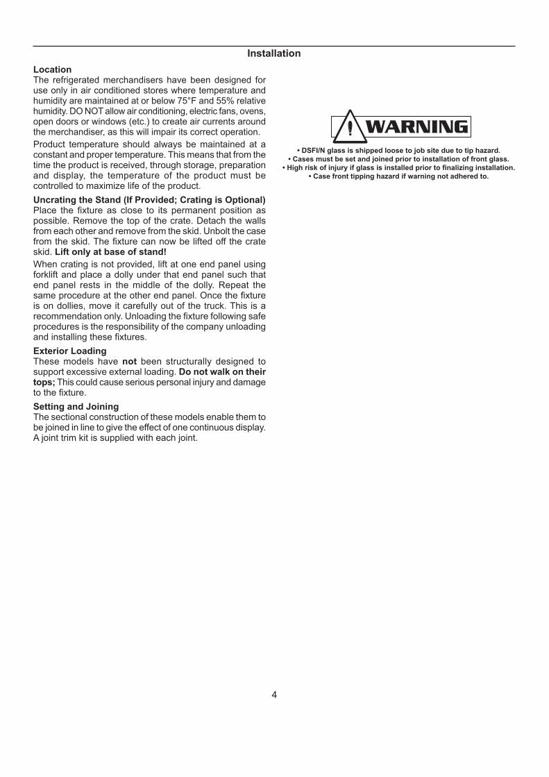
Uncrating the Stand (If Provided; Crating is Optional)Place the fi xture as close to its permanent position as possible. Remove the top of the crate. Detach the walls from each other and remove from the skid. Unbolt the case from the skid. The fi xture can now be lifted off the crate skid. Lift only at base of stand!
When crating is not provided, lift at one end panel using forklift and place a dolly under that end panel such that end panel rests in the middle of the dolly. Repeat the same procedure at the other end panel. Once the fi xture is on dollies, move it carefully out of the truck. This is a recommendation only. Unloading the fi xture following safe procedures is the responsibility of the company unloading and installing these fi xtures.
Exterior LoadingThese models have not been structurally designed to support excessive external loading. Do not walk on their tops; This could cause serious personal injury and damage to the fi xture.
Setting and JoiningThe sectional construction of these models enable them to be joined in line to give the effect of one continuous display. A joint trim kit is supplied with each joint.
• DSFI/N glass is shipped loose to job site due to tip hazard.
• Cases must be set and joined prior to installation of front glass.
• High risk of injury if glass is installed prior to finalizing installation.
• Case front tipping hazard if warning not adhered to.
5
LevelingIMPORTANT! IT IS IMPERATIVE THAT CASES BE LEVELED FROM FRONT TO BACK AND SIDE TO SIDE PRIOR TO JOINING. A LEVEL CASE IS NECESSARY TO INSURE PROPER OPERATION, WATER DRAINAGE, GLASS ALIGNMENT, AND OPERATION OF THE HINGES SUPPORTING THE GLASS. LEVELING THE CASE CORRECTLY WILL SOLVE MOST HINGE OPERATION PROBLEMS.
NOTE: A. To avoid removing concrete fl ooring, begin lineup
leveling from the highest point of the store fl oor.
B. When wedges are involved in a lineup, set them fi rst.
All cases were leveled and joined prior to shipment to insure the closest possible fi t when cases are joined in the fi eld. When joining, use a carpenters level and shim legs accordingly. Case must be raised correctly, under legs where support is best, to prevent damage to case.
1. Check level of fl oor where cases are to be set. Determine the highest point of the fl oor; cases will be set off this point.
2. Set fi rst case, and adjust legs over the highest part of the fl oor so that case is level. Prevent damage - case must be raised under leg or by use of 2x6 or 2x4 leg brace. Remove side and back leg braces after case is set.
3. Set second case as close as possible to the fi rst case and level case to the fi rst using the instructions in step one. The fronts of the cases should be in alignment. Caution: do not use connecting bolts to pull sections together.
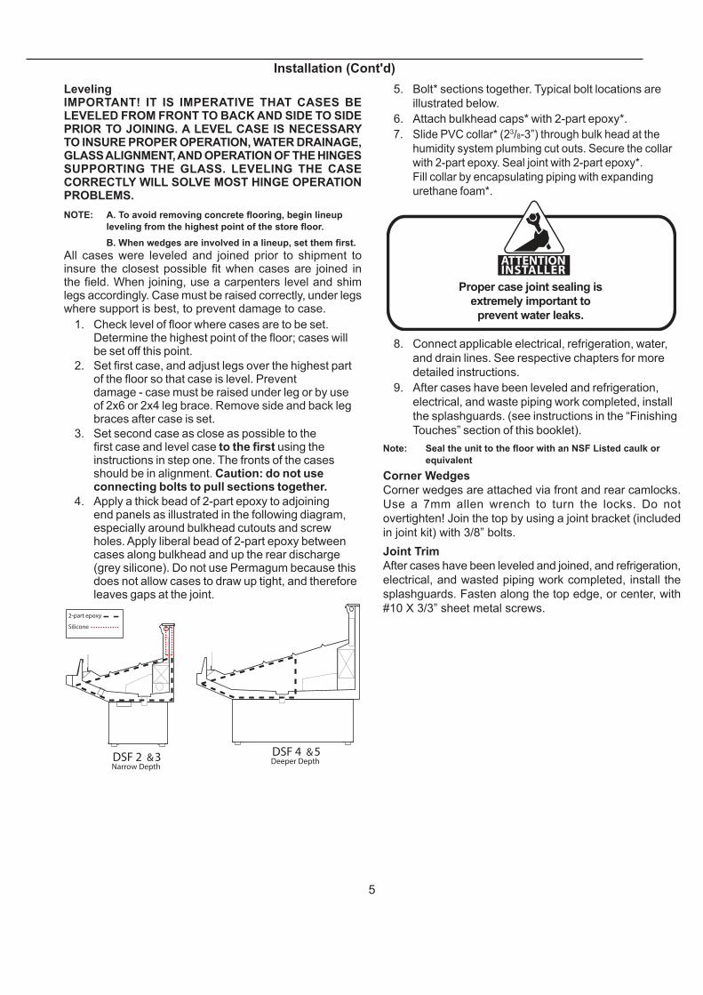
4. Apply a thick bead of 2-part epoxy to adjoining end panels as illustrated in the following diagram, especially around bulkhead cutouts and screw holes. Apply liberal bead of 2-part epoxy between cases along bulkhead and up the rear discharge (grey silicone). Do not use Permagum because this does not allow cases to draw up tight, and therefore leaves gaps at the joint.
DSF 4 &5Deeper Depth
2-part epoxy
Silicone
DSF 2 &3Narrow Depth
5. Bolt* sections together. Typical bolt locations are
illustrated below.
6. Attach bulkhead caps* with 2-part epoxy*.
7. Slide PVC collar* (23/8-3”) through bulk head at the
humidity system plumbing cut outs. Secure the collar
with 2-part epoxy. Seal joint with 2-part epoxy*.
Fill collar by encapsulating piping with expanding
urethane foam*.
Proper case joint sealing is
extremely important to
prevent water leaks.
ATTENTIONINSTALLER
8. Connect applicable electrical, refrigeration, water,
and drain lines. See respective chapters for more
detailed instructions.
9. After cases have been leveled and refrigeration,
electrical, and waste piping work completed, install
the splashguards. (see instructions in the “Finishing
Touches” section of this booklet).
Note: Seal the unit to the fl oor with an NSF Listed caulk or
equivalent
Corner Wedges
Corner wedges are attached via front and rear camlocks.
Use a 7mm allen wrench to turn the locks. Do not
overtighten! Join the top by using a joint bracket (included
in joint kit) with 3/8” bolts.
Joint Trim
After cases have been leveled and joined, and refrigeration,
electrical, and wasted piping work completed, install the
splashguards. Fasten along the top edge, or center, with
#10 X 3/3” sheet metal screws.
Installation (Cont'd)
6
Installation (Cont'd)
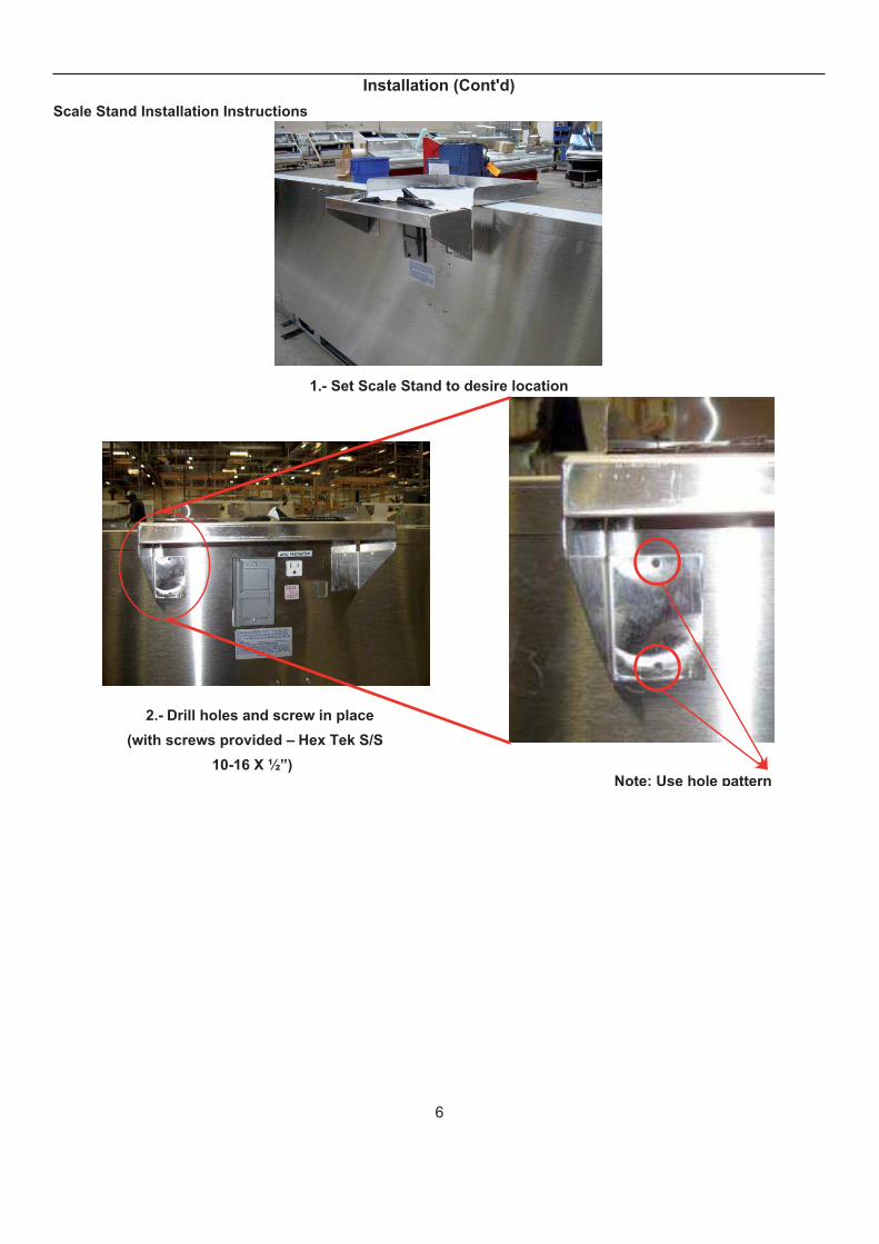
Scale Stand Installation Instructions
1.- Set Scale Stand to desire location
2.- Drill holes and screw in place
(with screws provided – Hex Tek S/S
10-16 X ½”)Note: Use hole pattern

7
Installation (Cont'd)
Wrapping Boards Installation Instructions
Step 1: Measure 6 inches from wrapping board end.Step 2: Measure 10 inches from top of the case.
Note: Line up 6 inch mark with 10 inch mark.
Step 3: Use bracket center hole to align with cross mark.
Note: Use pencil/marker to mark hole pattern.HOLE PATTERN
Step 4: Drill holes (7/32”)
Screws # 14 X 1”
Step 5: Install bracket with screws (provided)
Note: Repeat Steps 1 Thru 5 for Second Bracket Installation.

8
Installation (Cont'd)
Step 6: Install upper
support bracket
Step 7: mount wrap board on top of bracket using a ¼”
spacer to have a gap between rear wall and board. Step 8: screw bracket into wrap board
(screws provided -#8 X 1 ¼”)
Installation Complete
9
Installation (Cont'd)
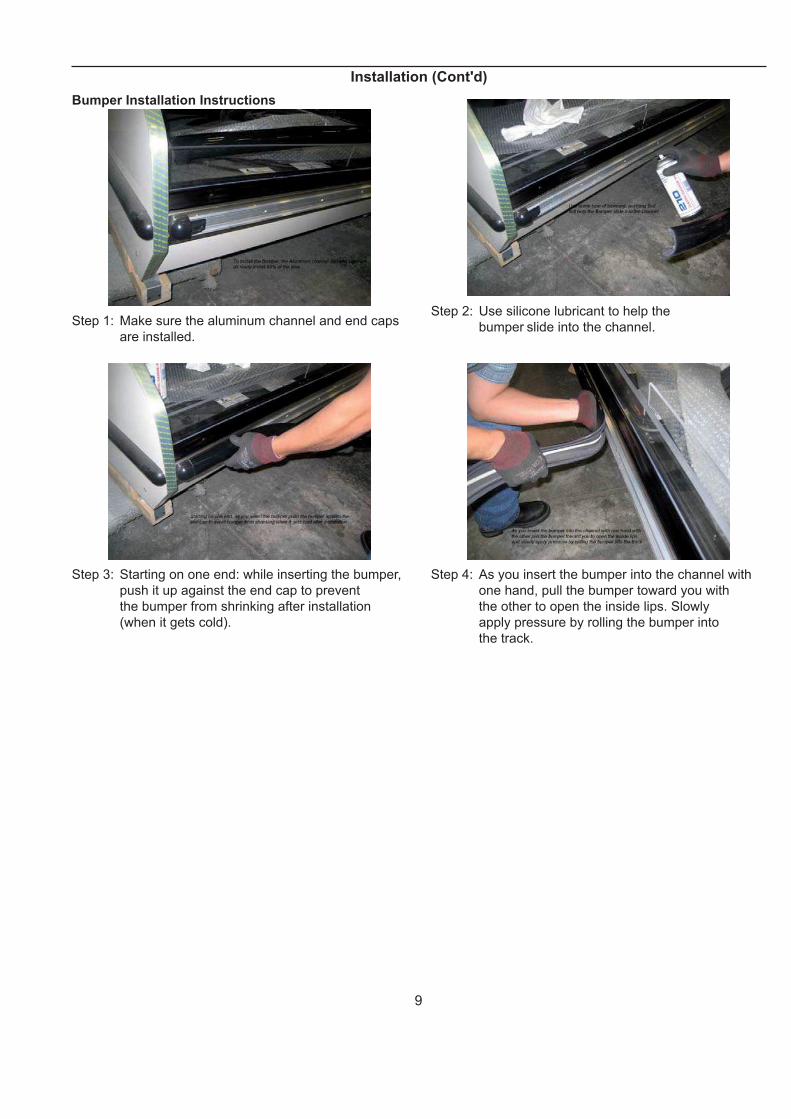
Bumper Installation Instructions
Step 1: Make sure the aluminum channel and end caps
are installed.
Step 2: Use silicone lubricant to help the
bumper slide into the channel.
Step 3: Starting on one end: while inserting the bumper,
push it up against the end cap to prevent
the bumper from shrinking after installation
(when it gets cold).
Step 4: As you insert the bumper into the channel with
one hand, pull the bumper toward you with
the other to open the inside lips. Slowly
apply pressure by rolling the bumper into
the track.
10
Installation (Cont'd)
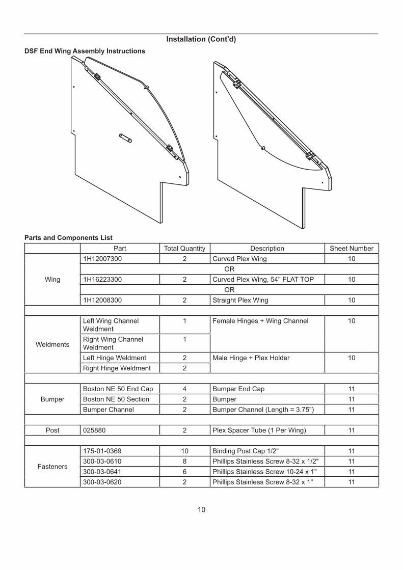
DSF End Wing Assembly Instructions
Parts and Components List
Part Total Quantity Description Sheet Number
Wing
1H12007300 2 Curved Plex Wing 10
OR
1H16223300 2 Curved Plex Wing, 54" FLAT TOP 10
OR
1H12008300 2 Straight Plex Wing 10
Weldments
Left Wing Channel
Weldment
1 Female Hinges + Wing Channel 10
Right Wing Channel
Weldment
1
Left Hinge Weldment 2 Male Hinge + Plex Holder 10
Right Hinge Weldment 2
Bumper
Boston NE 50 End Cap 4 Bumper End Cap 11
Boston NE 50 Section 2 Bumper 11
Bumper Channel 2 Bumper Channel (Length = 3.75") 11
Post 025880 2 Plex Spacer Tube (1 Per Wing) 11
Fasteners
175-01-0369 10 Binding Post Cap 1/2" 11
300-03-0610 8 Phillips Stainless Screw 8-32 x 1/2" 11
300-03-0641 6 Phillips Stainless Screw 10-24 x 1" 11
300-03-0620 2 Phillips Stainless Screw 8-32 x 1" 11

11
Installation (Cont'd)
1H12007300x 2
Curved Glass Model
1H12008300
Straight Glass Modelx 2
Front of CaseRear of Case
1H16223300
Curved Glass Model, 54" FLAT TOPx 2
This part is used when health codesrequire a horizontal end shield at 54"
from the ground.
Left Hinge Weldment x 2 Right Hinge Weldment x 2
Left Wing Channel Weldment x 1
Right Wing Channel Weldment x 1
12
Installation (Cont'd)
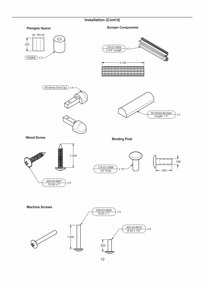
Plexiglas Spacer Bumper Components
025880 x 2
50 Series Bumper
Length = 3"x 2
50 Series End Cap x 4
.875
.750
175-01-5002
3 3/4" Lengthx 2
3.750
.500
300-03-0620
8-32 x 1"x 2
300-03-0610x 8
8-32 x 1/2"
Machine Screws
Binding PostWood Screw
.500175-01-0369
1/2" Postx 10
1.000
300-03-0641x 6
10-24 x 1"
1.000
.188
13
Installation (Cont'd)
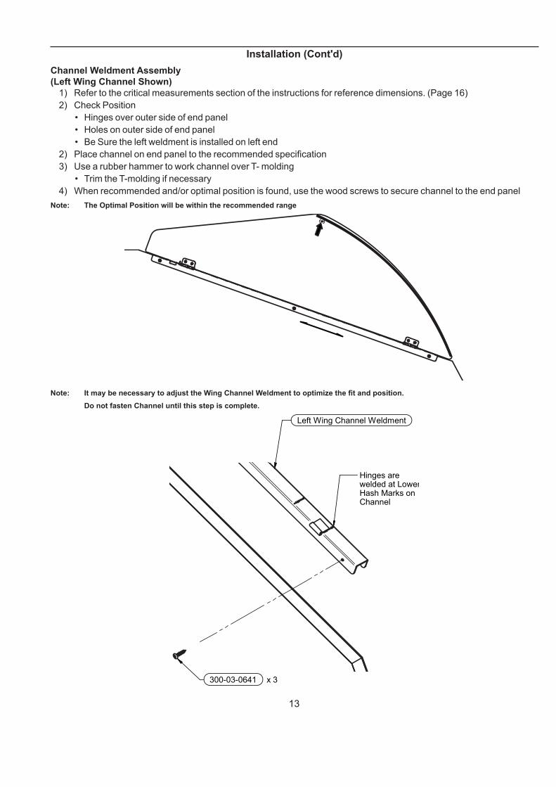
Channel Weldment Assembly
(Left Wing Channel Shown)
1) Refer to the critical measurements section of the instructions for reference dimensions. (Page 16)
2) Check Position
• Hinges over outer side of end panel
• Holes on outer side of end panel
• Be Sure the left weldment is installed on left end
2) Place channel on end panel to the recommended specifi cation
3) Use a rubber hammer to work channel over T- molding
• Trim the T-molding if necessary
4) When recommended and/or optimal position is found, use the wood screws to secure channel to the end panel
Note: The Optimal Position will be within the recommended range
Note: It may be necessary to adjust the Wing Channel Weldment to optimize the fi t and position.
Do not fasten Channel until this step is complete.
Left Wing Channel Weldment
Hinges are welded at LowerHash Marks on Channel
300-03-0641 x 3
14
Installation (Cont'd)
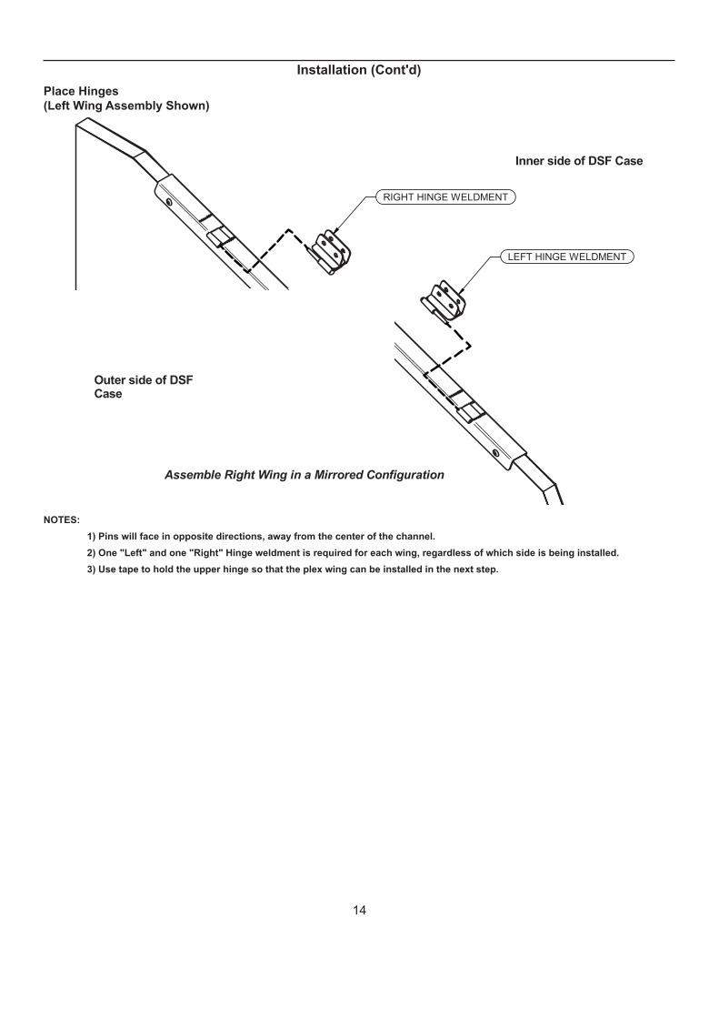
Place Hinges
(Left Wing Assembly Shown)
Outer side of DSFCase
Inner side of DSF Case
Assemble Right Wing in a Mirrored Configuration
RIGHT HINGE WELDMENT
LEFT HINGE WELDMENT
NOTES:
1) Pins will face in opposite directions, away from the center of the channel.
2) One "Left" and one "Right" Hinge weldment is required for each wing, regardless of which side is being installed.
3) Use tape to hold the upper hinge so that the plex wing can be installed in the next step.

15
Installation (Cont'd)
End Wing Attachment
(Left Wing Shown)
Outer side ofDSF Case
Inner side ofDSF Case
175-01-0369 x 4
300-03-0610 x 4
1) Place the plex wing into channels on the hinges.
2) Align all 4 holes on the wing with respective holes on hinges.
3) Securely fasten the binding posts. All binding posts are installed on the inner side.
Plex Post Installation
025880175-01-0369
300-03-0620
Outer side ofDSF Case
Inner side ofDSF Case
Assemble Right Wing in a Mirrored Configuration
16
Installation (Cont'd)
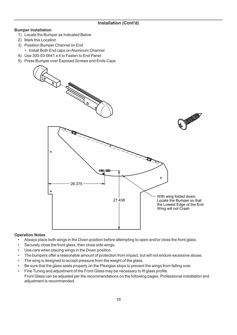
Bumper Installation
1) Locate the Bumper as Indicated Below
2) Mark this Location
3) Positiion Bumper Channel on End
• Install Both End caps on Aluminum Channel
4) Use 300-03-0641 x 4 to Fasten to End Panel
5) Press Bumper over Exposed Screws and Ends Caps
With wing folded down,Locate the Bumper so thatthe Lowest Edge of the EndWing will not Crash
27.438
26.375
Operation Notes
• Always place both wings in the Down position before attempting to open and/or close the front glass.
• Securely close the front glass, then close side wings.
• Use care when placing wings in the Down position.
• The bumpers offer a reasonable amount of protection from impact, but will not endure excessive abuse.
• The wing is designed to accept pressure from the weight of the glass.
• Be sure that the glass seats properly on the Plexiglas stops to prevent the wings from falling over.
• Fine Tuning and adjustment of the Front Glass may be necessary to fi t glass profi le.
Front Glass can be adjusted per the recommendations on the following pages. Professional installation and
adjustment is recommended.
17
Installation (Cont'd)
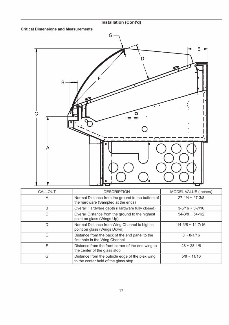
Critical Dimensions and Measurements
C
A
BF
G
D
E
CALLOUT DESCRIPTION MODEL VALUE (Inches)
A Normal Distance from the ground to the bottom of
the hardware (Sampled at the ends)
27-1/4 ~ 27-3/8
B Overall Hardware depth (Hardware fully closed) 3-5/16 ~ 3-7/16
C Overall Distance from the ground to the highest
point on glass (Wings Up)
54-3/8 ~ 54-1/2
D Normal Distance from Wing Channel to highest
point on glass (Wings Down)
14-3/8 ~ 14-7/16
E Distance from the back of the end panel to the
fi rst hole in the Wing Channel
8 ~ 8-1/16
F Distance from the front corner of the end wing to
the center of the glass stop
28 ~ 28-1/8
G Distance from the outside edge of the plex wing
to the center hold of the glass stop
5/8 ~ 11/16
18
Installation (Cont'd)
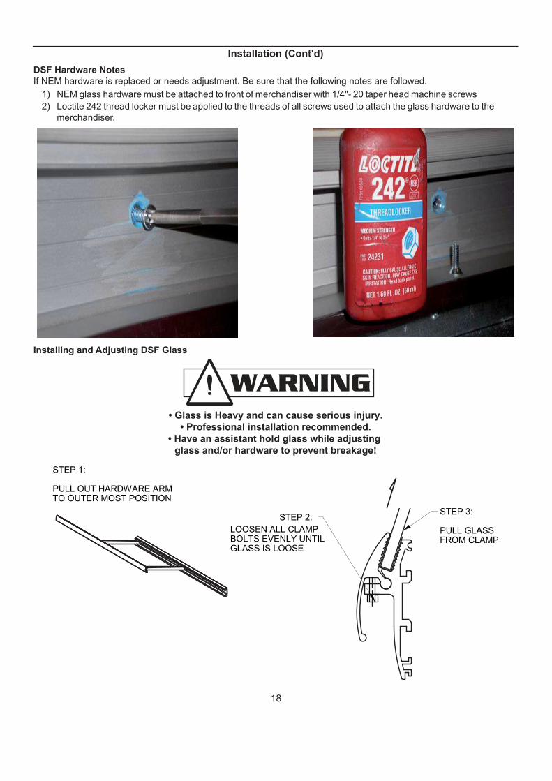
DSF Hardware Notes
If NEM hardware is replaced or needs adjustment. Be sure that the following notes are followed.
1) NEM glass hardware must be attached to front of merchandiser with 1/4"- 20 taper head machine screws
2) Loctite 242 thread locker must be applied to the threads of all screws used to attach the glass hardware to the
merchandiser.
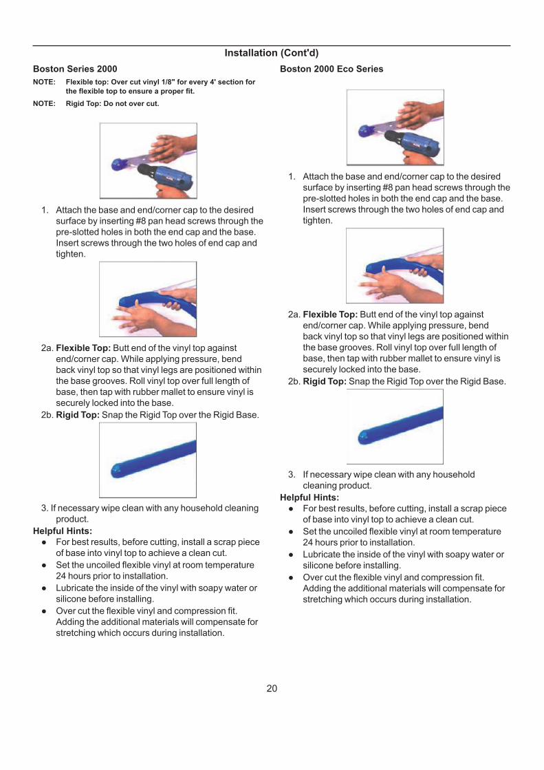
Installing and Adjusting DSF Glass
• Glass is Heavy and can cause serious injury.
• Professional installation recommended.
• Have an assistant hold glass while adjusting
glass and/or hardware to prevent breakage!
STEP 1:
PULL OUT HARDWARE ARM TO OUTER MOST POSITION
STEP 2:
LOOSEN ALL CLAMP BOLTS EVENLY UNTIL GLASS IS LOOSE
STEP 3:
PULL GLASS FROM CLAMP

19
Installation (Cont'd)
STEP 4:
ATTACH SHIM TO GASKET IN DESIREDPOSITION USING CLEAR 3/8" DOUBLESIDED TAPE
PLACE SHIMHERE TO ROTATEGLASS UPWARD
STEP 5:
REPLACE SHIMMEDGLASS AND TIGHTENALL CLAMP SCREWSEVENLY AND SECURELY
CASEINTERIOR
STEP 6:
CHECK GLASS HEIGHTAGAINST SPECIFICATIONS(PAGE 13).
REPEAT SHIM PROCEDURE IF MEASURED HEIGHT IS NOT WITHIN SPECIFICATIONS
ALTER THE SHIM LOCATION ON THE GASKETTO CHANGE THE DEGREE OF SHIM
PLACE SHIMHERE TO ROTATEGLASS DOWNWARD
NOTE: Place shims along the length of the glass in order to evenly distribute clamping forces.
Glass Stop and End Wing Final Position Notes
End Wings and End panels from the factory should have pre-drilled holes for the plex post and wing channel
respectively.
If a hole has not been pre-drilled into the side plex and end panels, observe the following notes:
1) The glass stop post must be precisely located on the end wing. Refer to dimensions G and H on page 16.
2) The wing channel must be located and mounted precisely on top of the end panel. Refer to dimension F on page 16.
20
Installation (Cont'd)
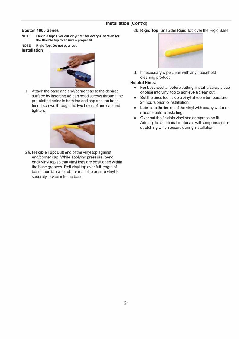
Boston Series 2000
NOTE: Flexible top: Over cut vinyl 1/8" for every 4' section for
the fl exible top to ensure a proper fi t.
NOTE: Rigid Top: Do not over cut.
1. Attach the base and end/corner cap to the desired
surface by inserting #8 pan head screws through the
pre-slotted holes in both the end cap and the base.
Insert screws through the two holes of end cap and
tighten.
2a. Flexible Top: Butt end of the vinyl top against
end/corner cap. While applying pressure, bend
back vinyl top so that vinyl legs are positioned within
the base grooves. Roll vinyl top over full length of
base, then tap with rubber mallet to ensure vinyl is
securely locked into the base.
2b. Rigid Top: Snap the Rigid Top over the Rigid Base.
3. If necessary wipe clean with any household cleaning
product.
Helpful Hints:
● For best results, before cutting, install a scrap piece
of base into vinyl top to achieve a clean cut.
● Set the uncoiled flexible vinyl at room temperature
24 hours prior to installation.
● Lubricate the inside of the vinyl with soapy water or
silicone before installing.
● Over cut the flexible vinyl and compression fit.
Adding the additional materials will compensate for
stretching which occurs during installation.
Boston 2000 Eco Series
1. Attach the base and end/corner cap to the desired
surface by inserting #8 pan head screws through the
pre-slotted holes in both the end cap and the base.
Insert screws through the two holes of end cap and
tighten.
2a. Flexible Top: Butt end of the vinyl top against
end/corner cap. While applying pressure, bend
back vinyl top so that vinyl legs are positioned within
the base grooves. Roll vinyl top over full length of
base, then tap with rubber mallet to ensure vinyl is
securely locked into the base.
2b. Rigid Top: Snap the Rigid Top over the Rigid Base.
3. If necessary wipe clean with any household
cleaning product.
Helpful Hints:
● For best results, before cutting, install a scrap piece
of base into vinyl top to achieve a clean cut.
● Set the uncoiled flexible vinyl at room temperature
24 hours prior to installation.
● Lubricate the inside of the vinyl with soapy water or
silicone before installing.
● Over cut the flexible vinyl and compression fit.
Adding the additional materials will compensate for
stretching which occurs during installation.
21
Installation (Cont'd)
Boston 1000 Series
NOTE: Flexible top: Over cut vinyl 1/8" for every 4' section for
the fl exible top to ensure a proper fi t.
NOTE: Rigid Top: Do not over cut.
Installation
1. Attach the base and end/corner cap to the desired
surface by inserting #8 pan head screws through the
pre-slotted holes in both the end cap and the base.
Insert screws through the two holes of end cap and
tighten.
2a. Flexible Top: Butt end of the vinyl top against
end/corner cap. While applying pressure, bend
back vinyl top so that vinyl legs are positioned within
the base grooves. Roll vinyl top over full length of
base, then tap with rubber mallet to ensure vinyl is
securely locked into the base.
2b. Rigid Top: Snap the Rigid Top over the Rigid Base.
3. If necessary wipe clean with any household
cleaning product.
Helpful Hints:
● For best results, before cutting, install a scrap piece
of base into vinyl top to achieve a clean cut.
● Set the uncoiled flexible vinyl at room temperature
24 hours prior to installation.
● Lubricate the inside of the vinyl with soapy water or
silicone before installing.
● Over cut the flexible vinyl and compression fit.
Adding the additional materials will compensate for
stretching which occurs during installation.
22
Installation (Cont'd)
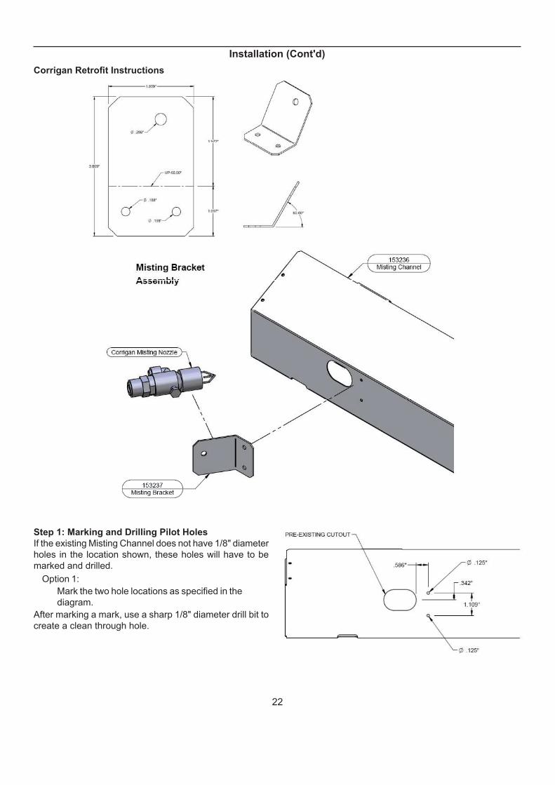
Corrigan Retrofi t Instructions
Step 1: Marking and Drilling Pilot Holes
If the existing Misting Channel does not have 1/8" diameter
holes in the location shown, these holes will have to be
marked and drilled.
Option 1:
Mark the two hole locations as specifi ed in the
diagram.
After marking a mark, use a sharp 1/8" diameter drill bit to
create a clean through hole.

23
Step 2: Attach misting nozzle to misting bracket
The spraying end of the nozzle must point toward the end
of the bracket with two holes.
See the diagram below.
Step 3: Attach Nozzle/Bracket assembly to Misting
Channel
The nozzle will protrude into the oblong cutout.
See the diagram below.
Installation (Cont'd)
Step 4: Final Assembly and Inspection
The nozzle should be positioned as shown. Some fi nal adjustment may be necessary to optimize misting, depending
on case operating conditions.
Make adjustments to angle by manually bending bracket if necessary. This may require the use of hand tools. Use eye
protection at all times.
Note: The nozzle tip should protrude into the cutout by approximately half of the nozzle head length.

24
Plumbing
Waste Outlet and P-TRAPThe waste outlet is located off the center of the case on one side allowing drip piping to be run lengthwise under the
fi xture. The water seal is facory installed. Do not tighten the
water seal where it connects to the drain fi tting. Twisting
the water seal "trap" can cause a water leak in the case's
bottom liner. Do not use thread sealant between ABS drain
fi tting and water seal.
A 1-1/2” P-TRAP and threaded adapter are supplied with each fi xture. The P-TRAP must be installed to prevent air leakage and insect entrance into the fi xture.
NOTE: PVC-DWV solvent cement is recommended. Follow the
manufacturer’s instructions.
Installing Condensate DrainPoorly or improperly installed condensate drains can seriously interfere with the operation of this refrigerator, and result in costly maintenance and product losses. Please follow the recommendations listed below when installing condensate drains to insure a proper installation:
1. Never use pipe for condensate drains smaller than the nominal diameter of the pipe or P-TRAP supplied with the case.
2. When connecting condensate drains, the P-TRAP must be used as part of the condensate drain to prevent air leakage or insect entrance. Store
plumbing system fl oor drains should be at least 14” off the center of the case to allow use of the P-TRAP pipe section. Never use two water seals in series in any one line. Double P-TRAPS in series will cause a lock and prevent draining.
3. Always provide as much down hill slope (“fall”) as
possible; 1/8” per foot is the preferred minimum.
PVC pipe, when used, must be supported to
maintain the 1/8” pitch and to prevent warping.
4. Avoid long runs of condensate drains. Long runs
make it impossible to provide the “fall” necessary for
good drainage.
5. Provide a suitable air break between the fl ood rim of
the fl oor drain and outlet of condensate drain. 1” is
ideal.
6. Prevent condensate drains from freezing:
a. Do not install condensate drains in contact with
non-insulated suction lines. Suction lines should
be insulated with a non absorbent insulation
material such as Armstrong’s Armafl ex.
b. Where condensate drains are located in dead
air spaces (between refrigerators or between a
refrigerator and a wall), provide means to prevent
freezing. The water seal should be insulated to
prevent condensation.
THE DRAIN AND WATER SEAL ARE FACTORY
INSTALLED. DO NOT USE THREAD SEALANT OR
OVERTIGHTEN THESE PARTS. DO NOT TWIST
WATER SEAL. DAMAGE TO THE DRAIN FITTING
OR WATER SEAL MAY OCCUR

25
Humidification
General Description
One contributor to the spoilage of fresh meats is
dehydration, which causes loss in weight and volume
(shrinkage) and product discoloration. As the refrigeration
system removes heat from the case, it also removes critical
moisture from the air, and any unwrapped products in the
case. The Humidity System replaces the moisture in the
air, in order to compensate for the moisture taken by the
refrigeration system, and disposed of down the drain line.
The system is built into the discharge plenum, and mixes
moisture laden air with refrigerated air before the air is
passed through - and around the product.
The system is constructed almost entirely of PVC pipe,
and uses air that is sub-cooled to approximately the
same temperature as the case. The sub-cooling of air
inhibits the formation of growth found to be a problem
in other humidifi cation systems. Maintenance is almost
unnecessary if you follow a few simple rules:
1. Keep the case clean.
2. Keep the water fi lter clean, and change it every six
to twelve months or sooner, depending on the kind
of water found in your area.
3. Flush the header every six (6) months, by loosening
the connecting “L”, then removing it from the case,
and fl ushing with a hose.
The DSF is capable of maintaining superb product quality
with the installation of the proper controlling devices.
These devices should be set according to the Hussmann’s
specifications. The humidity system should be properly
maintained. Incorrect settings and failure to maintain the
humidity system will result in short product life. Below
are a few guidelines for optimum performance and product
life:
• Set thermostat to cut in at the discharge temperature
designated in the case specifi cations section of the
appropriate installation guide or specifi cation sheet.
Maintain the recommended product temperature for
Deli, Meat, and Fish. DO NOT set temperature too
cold, as this causes product dehydration.
• Temperatures should be achieved by means of a
T-STAT and Suction Solenoid at each case. DO
NOT use EPR valves, Liquid Line Solenoids,
or electronic control devices of any kind. These
controls allow temperature swings that cause
dehydration and excessive energy consumption.
• Set defrost cycles as listed in the Case
Specifi cations Data for your particular case. The
number of defrosts per day should never change.
The duration of the defrost cycle may be adjusted to
meet conditions present at your location.
• Clean humidity system a minimum of every 90 days
for proper system operation.
• Work and rotate product - not to exceed a four (4)
hour period.
• At night, turn off case lights, and cover unwrapped
product with moistened cheesecloth or fabric towels.
• Keep meat holding box at 32°F.
• Keep meat prep room refrigerated at 55°F.
• Meat Bloom Box (if applicable) should be at 36°F.
• Meat must enter the case at 40°F or below. Product
deteriorates rapidly above 40°F.
• Clean, sanitary conditions are required throughout
the meat holding, prep, and work areas.
• Do not display product directly within the air discharge
• Turn and rotate meat. The blood works down
through the meat over time, which causes the top
surface to discolor and dehydrate. Turn meat 3-4
times per day.
• It is not required to remove product from case
overnight. Turn off case lights, and cover product
with moistened cheesecloth or fabric towel. This
helps slow down product dehydration, by taking
moisture from the cloth and not the product. This is
an old method used by meat shops for many years,
as it extends product life.
• Cold coils remove heat and moisture from the
case and deposit this as frost onto the coil. Thus a
defrost is required to remove this frost. Our humidity
system induces moisture into the case, and helps
slow down the dehydration process. The only other
moisture in the case is that which is in the product.
A single level of meat will dry out faster than a fully
loaded case with 3-4 levels of meat.
• The colder the case, the faster the product loses its
moisture and shelf life. It is very important to maintain
a constant, even, correct, product temperature.
Humidifi cation System Hookups
Remove the raceway panel on the lower back of the case.
The pre-piped water shut-off valve and the water fi lter are
located on the left hand side of the case. The water line
(which is a 1/4” OD copper fi tting) can be connected to
the ball shut-off valve, by means of a compression fi tting
(supplied). The line should be one size larger than the
supply line. The line can then be run from one case to
another from within the raceway(s) using Tee connectors.
Before connecting the water to the humidity system, it is
best to purge the line to fl ush any debris that may clog the
water fi lter. If the water line requires purging after the cases
are hooked together, it is not necessary to check each one.
Simply shut ball valves to each humidity system, remove
the water line from the last case in the fl ow, and purge.
By doing this as a precautionary measure, you may avoid
problems and repeat servicing.
26
Manifold Flush System
General Description
Twice a day for two (2) minutes, a high pressure water
stream will fl ush most residue build-up from the bottom of
the manifold chamber. This is the area that residue builds
and expands from. Frequency of this periodic maintenance
will vary depending on water mineral content and sanitary
conditions.
Automatic Flush System
Electrical components are located within the electrical
raceway. Electrical components in this area are 115V
AC. Step-down transformer is located in wire-way, and is
controlled by pump switch. Water fl ow for fl ush system is
rated at 0.25 GPM at 60PSI water pressure. Flush nozzle
located in the rear of the case.
Basic System Operation:
1. Filtered water is supplied to the 115V solenoid
valve.
2. At a time of day determined by you, the 115V time
clock will energize the solenoid for 2 minutes.
Start Up:
1. Manually move time clock to initiate a fl ush cycle.
2. Observe that fl ush nozzle is spraying down center of
manifold chamber.
3. Set clock to correct time of day.
4. Set trip pins to the “time of day system is to fl ush”
(NOTE: 2 fl ush/day!)
Manual Flush System
Water valve is located on the outside of the case, in the
rear, on the left hand side as viewed from the rear.
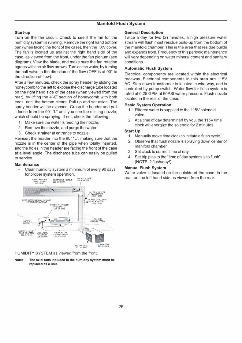
Start-up
Turn on the fan circuit. Check to see if the fan for the
humidity system is running. Remove the right hand bottom
pan (when facing the front of the case), then the TXV cover.
The fan is located up against the right hand side of the
case, as viewed from the front, under the fan plenum (see
diagram). View the blade, and make sure the fan rotation
agrees with the air fl ow arrows. Turn on the water, by turning
the ball valve in the direction of the fl ow (OFF is at 90° to
the direction of fl ow).
After a few minutes, check the spray header by sliding the
honeycomb to the left to expose the discharge tube located
on the right hand side of the case (when viewed from the
rear), by lifting the 4’-0” section of honeycomb with both
ends, until the bottom clears. Pull up and set aside. The
spray header will be exposed. Grasp the header and pull
it loose from the 90° “L” until you see the misting nozzle,
which should be spraying. If not, check the following:
1. Make sure the water is feeding the nozzle.
2. Remove the nozzle, and purge the water.
3. Check strainer at entrance to nozzle.
Reinsert the header into the 90° “L”, making sure that the
nozzle is in the center of the pipe when totally inserted,
and the holes in the header are facing the front of the case
at a level angle. The discharge tube can easily be pulled
to service.
Maintenance
• Clean humidity system a minimum of every 90 days
for proper system operation.
SCOTTDALE NOZZLE225-01-2089A
WATERSUPPLY
SPRAY HEADERRUNS LENGTH
OF CASE
WATER FILTER3 STAGE #00015
225-01-2026
3" AXIAL FAN225-01-20262ND FAN USED
IN 12' CASE
REAR INTERIOR WALL OF CASEVIEWED FROM FRONT
BALL VALVEHAMMON
225-01-2026
1/4" 100 X 1/8FPTSW ADAPTER
1/4" OD X 1/8" FPTSW ADAPTER225-01-3059
1/8" MPT X 1/4" COMPPVC ADAPTER
225-01-30591/4"MPT X 1/4" COMP
PVC ADAPTER225-01-2026
1/4"MPT X 1/4" ODCOMP ADAPTER
225-01-1312
PAN ANDACCESS PANEL
HUMIDITY SYSTEM as viewed from the front.
Note: The axial fans included in the humidity system must be
replaced as a unit.

27
Refrigerant Type
The standard refrigerant will be R-22 unless otherwise
specifi ed on the customer order. Check the serial plate on
the case for information.
Piping
The refrigerant line outlets are located under the case.
Locate fi rst the electrical box, the outlets are then on the
same side of the case but at the opposite end. Insulate
suction lines to prevent condensation drippage.
Refrigeration Lines
Liquid Suction
3/8” O.D. 5/8” O.D.
NOTE: The standard coil is piped at 5/8” (suction); however,
the store tie-in may vary depending on the number of
coils and the draw the case has. Depending on the case
setup, the connecting point in the store may be 5/8”, 7/8”,
or 11/8”. Refer to the particular case you are hooking up.
Refrigerant lines should be sized as shown on the
refrigeration legend furnished by the store.
Install P-TRAPS (oil traps) at the base of all suction line
vertical risers.
Pressure drop can rob the system of capacity. To keep the
pressure drop to a minimum, keep refrigerant line run as
short as possible, using the minimum number of elbows.
Where elbows are required, use long radius elbows only.
Control Settings
See DSF, DSFM technical data sheet for the appropriate
settings for your merchandiser. Maintain these parameters
to achieve near constant product temperatures. Product
temperature should be measured first thing in the
morning, after having been refrigerated overnight. For all
multiplexing, defrost should be time terminated. Defrost
times should be as directed in the DSF, DSFM technical
data sheet. The number of defrosts per day should never
change. The duration of the defrost cycle may be adjusted
to meet conditions present at your location.
Access to TX Valves and Drain Lines
Mechanical - Remove product from end of case. Remove
product racks. Remove refrigeration and drain access
panels (labeled). TX valve (mechanical only) and drain are
located under each access panel at end of the case.
Electronic - The Electronic Expansion valve master and
slave cylinder(s) are located within the electrical access
panel(s).
Electronic Expansion Valve (Optional)
A wide variety of electronic expansion valves and case
controllers can be utilized. Please refer to EEV and
controller manufacturers information sheet. Sensors for
electronic expansion valves will be installed on the coil inlet,
coil outlet, and in the discharge air. (Some supermarkets
require a 4th sensor in the return air). Case controllers will
be located in the electrical raceway or under the case.
Thermostatic Expansion Valve Location
This device is located on the same side as the refrigeration
stub. A balanced port expansion valve model is furnished
as standard equipment, unless otherwise specifi ed by
customer.
Expansion Valve Adjustment
Expansion valves must be adjusted to fully feed the
evaporator. Before attempting any adjustments, make
sure the evaporator is either clear or very lightly covered
with frost, and that the fi xture is within 10°F of its expected
operating temperature.
Measuring the Operating Superheat
1. Determine the suction pressure with an accurate
pressure gauge at the evaporator outlet.
2. From a refrigerant pressure temperature chart,
determine the saturation temperature at the
observed suction pressure.
3. Measure the temperature of the suction gas at the
thermostatic remote bulb location.
4. Subtract the saturation temperature obtained in step
No. 2 from the temperature measured in step No. 3.
5. The difference is superheat.
6. Set the superheat for 5°F - 7°F.
T-STAT Location
T-STATS are located within the electrical raceway of the 4’
or 5’ main section of the case. In all the cases, the T-STAT
is located on the same side of the case. If you are looking
at the case from the back, it is on the left hand side.
Refrigeration
NOTE: Only one T-stat per lineup.
T-Stat
Center Display
28
29
30

31

32
33
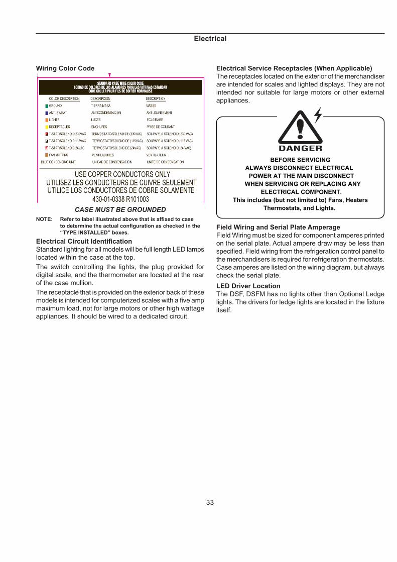
Wiring Color Code
CASE MUST BE GROUNDED
NOTE: Refer to label illustrated above that is affi xed to case
to determine the actual confi guration as checked in the
“TYPE INSTALLED” boxes.
Electrical Circuit Identifi cation
Standard lighting for all models will be full length LED lamps
located within the case at the top.
The switch controlling the lights, the plug provided for
digital scale, and the thermometer are located at the rear
of the case mullion.
The receptacle that is provided on the exterior back of these
models is intended for computerized scales with a fi ve amp
maximum load, not for large motors or other high wattage
appliances. It should be wired to a dedicated circuit.
Electrical Service Receptacles (When Applicable)
The receptacles located on the exterior of the merchandiser
are intended for scales and lighted displays. They are not
intended nor suitable for large motors or other external
appliances.
BEFORE SERVICING
ALWAYS DISCONNECT ELECTRICAL
POWER AT THE MAIN DISCONNECT
WHEN SERVICING OR REPLACING ANY
ELECTRICAL COMPONENT.
This includes (but not limited to) Fans, Heaters
Thermostats, and Lights.
Field Wiring and Serial Plate Amperage
Field Wiring must be sized for component amperes printed
on the serial plate. Actual ampere draw may be less than
specifi ed. Field wiring from the refrigeration control panel to
the merchandisers is required for refrigeration thermostats.
Case amperes are listed on the wiring diagram, but always
check the serial plate.
LED Driver Location
The DSF, DSFM has no lights other than Optional Ledge
lights. The drivers for ledge lights are located in the fi xture
itself.
Electrical
34
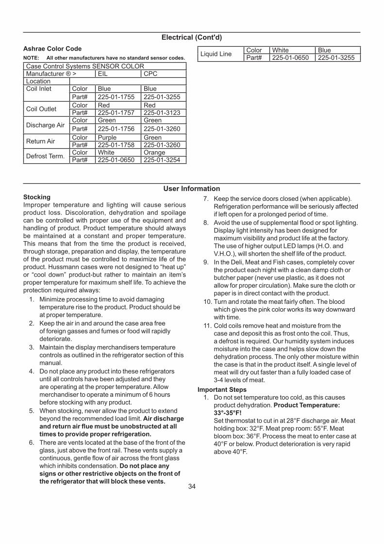
Ashrae Color Code
NOTE: All other manufacturers have no standard sensor codes.
Case Control Systems SENSOR COLOR Manufacturer ® > EIL CPC Location Coil Inlet
Color Blue Blue
Part# 225-01-1755 225-01-3255
Coil Outlet Color Red Red Part# 225-01-1757 225-01-3123
Discharge Air Color Green Green
Part# 225-01-1756 225-01-3260
Return Air Color Purple GreenPart# 225-01-1758 225-01-3260
Defrost Term. Color White OrangePart# 225-01-0650 225-01-3254
Liquid Line Color White BluePart# 225-01-0650 225-01-3255
Electrical (Cont'd)
User InformationStocking
Improper temperature and lighting will cause serious
product loss. Discoloration, dehydration and spoilage
can be controlled with proper use of the equipment and
handling of product. Product temperature should always
be maintained at a constant and proper temperature.
This means that from the time the product is received,
through storage, preparation and display, the temperature
of the product must be controlled to maximize life of the
product. Hussmann cases were not designed to “heat up”
or “cool down” product-but rather to maintain an item’s
proper temperature for maximum shelf life. To achieve the
protection required always:
1. Minimize processing time to avoid damaging
temperature rise to the product. Product should be
at proper temperature.
2. Keep the air in and around the case area free
of foreign gasses and fumes or food will rapidly
deteriorate.
3. Maintain the display merchandisers temperature
controls as outlined in the refrigerator section of this
manual.
4. Do not place any product into these refrigerators
until all controls have been adjusted and they
are operating at the proper temperature. Allow
merchandiser to operate a minimum of 6 hours
before stocking with any product.
5. When stocking, never allow the product to extend
beyond the recommended load limit. Air discharge
and return air fl ue must be unobstructed at all
times to provide proper refrigeration.
6. There are vents located at the base of the front of the
glass, just above the front rail. These vents supply a
continuous, gentle fl ow of air across the front glass
which inhibits condensation. Do not place any
signs or other restrictive objects on the front of
the refrigerator that will block these vents.
7. Keep the service doors closed (when applicable).
Refrigeration performance will be seriously affected
if left open for a prolonged period of time.
8. Avoid the use of supplemental fl ood or spot lighting.
Display light intensity has been designed for
maximum visibility and product life at the factory.
The use of higher output LED lamps (H.O. and
V.H.O.), will shorten the shelf life of the product.
9. In the Deli, Meat and Fish cases, completely cover
the product each night with a clean damp cloth or
butcher paper (never use plastic, as it does not
allow for proper circulation). Make sure the cloth or
paper is in direct contact with the product.
10. Turn and rotate the meat fairly often. The blood
which gives the pink color works its way downward
with time.
11. Cold coils remove heat and moisture from the
case and deposit this as frost onto the coil. Thus,
a defrost is required. Our humidity system induces
moisture into the case and helps slow down the
dehydration process. The only other moisture within
the case is that in the product itself. A single level of
meat will dry out faster than a fully loaded case of
3-4 levels of meat.
Important Steps
1. Do not set temperature too cold, as this causes
product dehydration. Product Temperature:
33°-35°F!
Set thermostat to cut in at 28°F discharge air. Meat
holding box: 32°F. Meat prep room: 55°F. Meat
bloom box: 36°F. Process the meat to enter case at
40°F or below. Product deterioration is very rapid
above 40°F.
35
User Information (Cont'd)
2. Temperature control should be by means of a
T-STAT and Suction Stop Solenoid at each case.
Do not use EPR valves, Liquid Line Solenoids or
electronic control devices of any kind, as these
allow temperature swings causing dehydration and
excessive energy consumption.
3. Product should be worked and rotated on a regular
basis, not to exceed a 4-hour period.
4. At night, turn off case lights and cover the product
with a damp (not wet) cloth similar to cheese cloth
(etc.). This should be washed out in the morning and
kept in a walk-in box during the day - so that it is cool
and moist when covering the product.
5. Discharge air temperature should be approximately
26°F, with between 150-200 FPM air velocity. Do not
display product directly within the air discharge.
6. Clean Humidity system a minimum of every 90 days
for proper system operation.
Case Cleaning
Long life and satisfactory performance of any equipment
are dependent upon the care given to it. To insure long
life, proper sanitation and minimum maintenance costs,
the refrigerator should be thoroughly cleaned frequently.
SHUT OFF FAN DURING CLEANING PROCESS. It can be
unplugged within the case, or shut off case at the source.
The interior bottom may be cleaned with any domestic soap
or detergent based cleaners. Sanitizing solutions will not
harm the interior bottom, however, these solutions should
always be used according to the manufacturer’s directions.
It is essential to establish and regulate cleaning procedures.
This will minimize bacteria causing discoloration which
leads to degraded product appearance and signifi cantly
shortening product shelf life.
Soap and hot water are not enough to kill this bacteria. A
sanitizing solution must be included with each cleaning
process to eliminate this bacteria.
1. Scrub thoroughly, cleaning all surfaces, with soap
and hot water.
2. Rinse with hot water, but do not fl ood.
3. Apply the sanitizing solution according to the
manufacturer’s directions.
4. Rinse thoroughly.
5. Dry completely before resuming operation.
Cleaning Glass and Mirrors
Only use a soft cloth and water for cleaning any glass
or mirrored components. Be sure to rinse and/or dry
completely.
Never use hot water on cold glass surfaces! It may
shatter and cause serious injury! Allow glass surfaces
to warm fi rst.
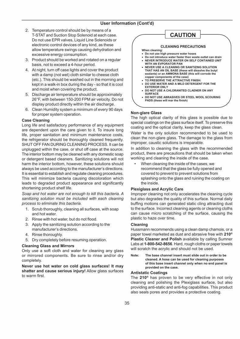
CLEANING PRECAUTIONS When cleaning:
• Do not use high pressure water hoses
• Do not introduce water faster then waste outlet can drain
• NEVER INTRODUCE WATER ON SELF CONTAINED UNIT WITH AN EVPORATOR PAN
• NEVER USE A CLEANING OR SANITIZING SOLUTION THAT HAS AN OIL BASE (these will dissolve the butyl sealants) or an AMMONA BASE (this will corrode the copper components of the case)
• TO PRESERVE THE ATTRACTIVE FINISH:
• DO USE WATER AND A MILD DETERGENT FOR THE EXTERIOR ONLY
• DO NOT USE A CHLORANITED CLAENER ON ANY SURFACE
• DO NOT USE ABRASIVES OR STEEL WOOL SCOURING PADS (these will mar the finish)
CAUTION
Non-glare Glass
The high optical clarity of this glass is possible due to
special coatings on the glass surface itself. To preserve this
coating and the optical clarity, keep the glass clean.
Water is the only solution recommended to be used to
clean the non-glare glass. The damage to the glass from
improper, caustic solutions is irreparable.
In addition to cleaning the glass with the recommended
product, there are precautions that should be taken when
working and cleaning the inside of the case.
• When cleaning the inside of the cases, we
recommend that the glass be fully opened and
covered to prevent to prevent solutions from
splashing onto the glass and ruining the coating on
the inside.
Plexiglass and Acrylic Care
Improper cleaning not only accelerates the cleaning cycle
but also degrades the quality of this surface. Normal daily
buffi ng motions can generated static cling attracting dust
to the surface. Incorrect cleaning agents or cleaning cloths
can cause micro scratching of the surface, causing the
plastic to haze over time.
Cleaning
Hussmann recommends using a clean damp chamois, or a
paper towel marketed as dust and abrasive free with 210®
Plastic Cleaner and Polish available by calling Sumner
Labs at 1-800-542-8656. Hard, rough cloths or paper towels
will scratch the acrylic and should not be used.
Note: The base channel insert must slide out in order to be
cleaned. A hose can be used for cleaning purposes
of this base insert channel only when no end panel is
provided on the case.
Antistatic Coatings
The 210® has proven to be very effective in not only
cleaning and polishing the Plexiglass surface, but also
providing anti-static and anti-fog capabilities. This product
also seals pores and provides a protective coating.

36
Maintenance
BEFORE SERVICING
ALWAYS DISCONNECT ELECTRICAL
POWER AT THE MAIN DISCONNECT
WHEN SERVICING OR REPLACING ANY
ELECTRICAL COMPONENT.
This includes (but not limited to) Fans, Heaters
Thermostats, and Lights.
Evaporator Fans
The evaporator fans are located at the center front of these
merchandisers directly beneath the display pans.
Should fans or blades need servicing, always replace
fan blades with the raised embossed side of the blade
TOWARD THE MOTOR.
Copper Coils
The copper coils used in Hussmann merchandisers may
be repaired in the fi eld. Materials are available from local
refrigeration wholesalers.
Hussmann recommends using #15 Sil-Fos for repairs.
Tips and Troubleshooting
Before calling for service, check the following:
1. Check electrical power supply to the equipment for
connection.
2. Check fi xture loading. Overstocking case will affect
its proper operation.
3. If frost is collecting on fi xture and/or product, check
that Humidity Control is working properly, and that
no outside doors or windows are open - allowing
moisture to enter store.
FOR PROMPT SERVICE
When contacting the factory,
be sure to have the Case Model and Serial
Number handy. This information is on a plate
located on the case itself.
Stainless Steel Cleaning and Care
There are three basic things, which can break down your
stainless steel’s passivity layer and allow corrosion.
1. Mechanical Abrasion
Mechanical Abrasion means those things that
will scratch the steels surface. Steel Pads, wire
Brushes, and Scrapers are prime examples.
2. Water
Water comes out of our tap in varying degrees of
hardness. Depending on what part of the country
you live in, you may have hard or soft water. Hard
water may leave spots. Also, when heated, hard
water leaves deposits behind that if left to sit, will
break down the passive layer and rust your stainless
steel. Other deposits from food preparation and
service must be properly removed.
3. Chlorides
Chlorides are found nearly everywhere. They
are in water, food and table salt. One of the worst
perpetrators of chlorides can come from household
and industrial cleaners.
Don’t Despair! Here are a few steps that can help prevent
stainless steel rust.
1. Use the Proper Tools
When cleaning your stainless steel products, take
care to use non-abrasive tools. Soft Clothes and
plastic scouring pads will NOT harm the steel’s
passive layer. Stainless steel pads can also be
used but the scrubbing motion must be in the same
direction of the manufacturer’s polishing marks.
2. Clean With the Polish Lines
Some stainless steels come with visible polishing
lines or “grain”. When visible lines are present, you
should ALWAYS scrub in a motion that is parallel to
them. When the grain cannot be seen, play it safe
and use a soft cloth or plastic scouring pad.
37
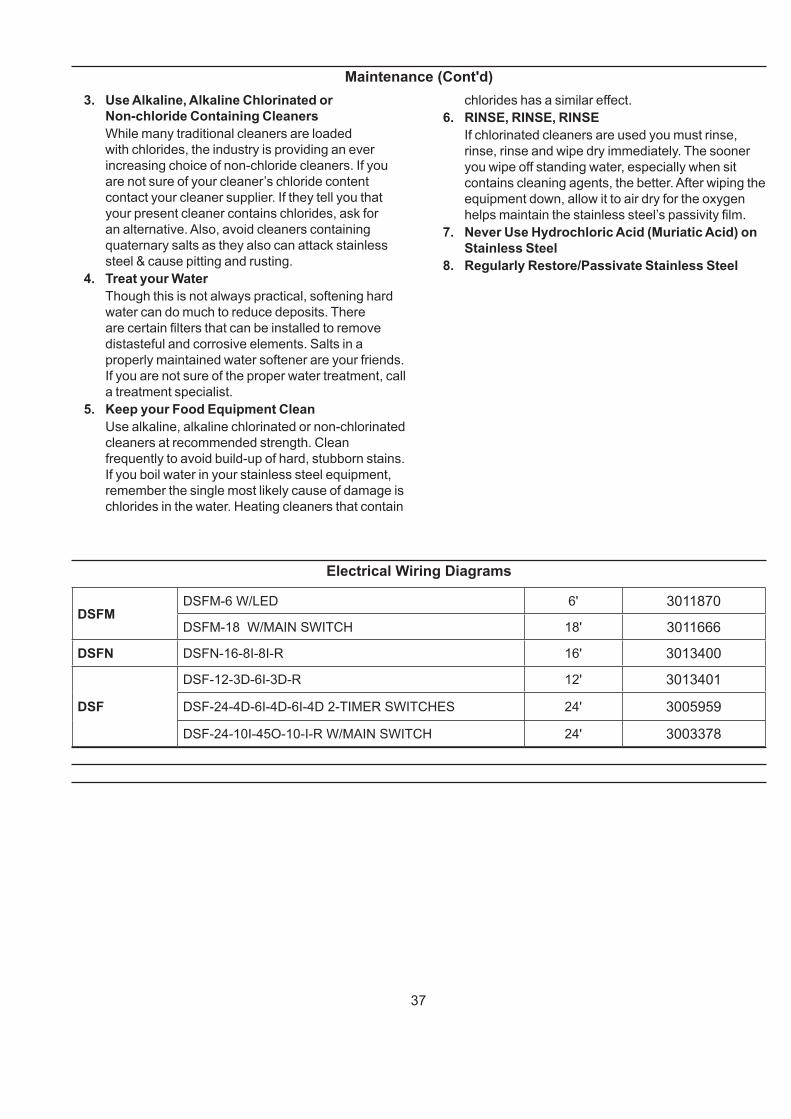
Electrical Wiring Diagrams
DSFMDSFM-6 W/LED 6' 3011870
DSFM-18 W/MAIN SWITCH 18' 3011666
DSFN DSFN-16-8I-8I-R 16' 3013400
DSF
DSF-12-3D-6I-3D-R 12' 3013401
DSF-24-4D-6I-4D-6I-4D 2-TIMER SWITCHES 24' 3005959
DSF-24-10I-45O-10-I-R W/MAIN SWITCH 24' 3003378
3. Use Alkaline, Alkaline Chlorinated or
Non-chloride Containing Cleaners
While many traditional cleaners are loaded
with chlorides, the industry is providing an ever
increasing choice of non-chloride cleaners. If you
are not sure of your cleaner’s chloride content
contact your cleaner supplier. If they tell you that
your present cleaner contains chlorides, ask for
an alternative. Also, avoid cleaners containing
quaternary salts as they also can attack stainless
steel & cause pitting and rusting.
4. Treat your Water
Though this is not always practical, softening hard
water can do much to reduce deposits. There
are certain fi lters that can be installed to remove
distasteful and corrosive elements. Salts in a
properly maintained water softener are your friends.
If you are not sure of the proper water treatment, call
a treatment specialist.
5. Keep your Food Equipment Clean
Use alkaline, alkaline chlorinated or non-chlorinated
cleaners at recommended strength. Clean
frequently to avoid build-up of hard, stubborn stains.
If you boil water in your stainless steel equipment,
remember the single most likely cause of damage is
chlorides in the water. Heating cleaners that contain
chlorides has a similar effect.
6. RINSE, RINSE, RINSE
If chlorinated cleaners are used you must rinse,
rinse, rinse and wipe dry immediately. The sooner
you wipe off standing water, especially when sit
contains cleaning agents, the better. After wiping the
equipment down, allow it to air dry for the oxygen
helps maintain the stainless steel’s passivity fi lm.
7. Never Use Hydrochloric Acid (Muriatic Acid) on
Stainless Steel
8. Regularly Restore/Passivate Stainless Steel
Maintenance (Cont'd)

38
HUSSMANN_GDF_1.1SHEETSIZEDMATERIAL - N/A
THIRDANGLE
PROJECTION
UNLESS OTHERWISE SPECIFIED DIMENSIONS ARE IN INCHES.
DRAWN BY -CRAIG BOOREY
APPROVED BY - CRAIG BOOREY
TOLERANCES ARE:DECIMALS .XX u.03, .XXX u.010
ANGLES u 2v
DATE DRAWN - 7-25-16ECN-CAP-0003047
REVIEWED BY -CRAIG BOOREY REF -
3011870
DSFM-6 W/LED
REV ECN DATE REVISION DESCRIPTION REV BY CHKD BY APPR BY
A ECN-CAP-0003047 2016/07/25 RELEASED TO PRODUCTION CB CB CB
REVISION HISTORY
NOTES:CASE MUST BE GROUNDEDWHEN PASSING WIRES THROUGH METAL HOLES A GROMMET MUST BE USED A
SHEET 1 OF 1
CIRCUIT #1
L1
LOADING
2.3120V
EVAP FANS(2) 125-01-0615A0.62A @ 120VAC
BUNDLEBROWN
HUMDITY FAN125-01-2011-H.16A @ 120VAC
BUNDLEBROWN
BLACK#14
WHITE#14
BLACK#14
WHITE#14
M
BLACK#14
WHITE#14
WARMER125-01-0767RAYCHEM10BUT-CR-10W60W .50A@ 120VAC
BUNDLEPURPLE
TX
4
N
31
2
FLUSH SYSTEMSOLENOID225-01-1335
BUNDLELABELEDFLUSHSYSTEM
BLACK#14
WHITE#14
TIME CLOCK8045-00/20125-01-0710
L1 N
CIRCUIT #1
TIPPETTE SWITCH125-01-0311
L1
NG
LOADING120 V
L1L2L3
~~~
15.0
NOTE: CASE MUST BEGROUNDED
CIRCUIT #2
~120 VAC - 1Ø - 50/60 Hz.
DUPLEX125-01-3178
BLK#14
WHT#14
GRN#14
BUNDLEBLACK &WHITEB
LACK#14
WHITE#14
T-STAT225-01-0707
SOLENOID225-01-1332.14A @ 120VAC
M M
OPTIONAL
BUNDLEORANGE
LIGHT SWITCH125-01-0307
WHT#14
BLK#14
CANOPY
LEDDRIVER
LIGHT CIRCUIT0.27A 29.4W @ 120V
RED+
BLUE-
3'LEDLIGHT
3'LEDLIGHT
Wirin
g D
iag
ram
s

39
HUSSMANN_GDF_1.1SHEETSIZEDMATERIAL - N/A
THIRDANGLE
PROJECTION
UNLESS OTHERWISE SPECIFIED DIMENSIONS ARE IN INCHES.
DRAWN BY -CRAIG BOOREY
APPROVED BY - CRAIG BOOREY
TOLERANCES ARE:DECIMALS .XX u.03, .XXX u.010
ANGLES u 2v
DATE DRAWN - 7-21-16ECN-CAP-0003047
REVIEWED BY -CRAIG BOOREY REF -
3011666
DIAGRAM-DSFM-18-R
REV ECN DATE REVISION DESCRIPTION REV BY CHKD BY APPR BY
A ECN-CAP-0003047 2016/07/21 RELEASED TO PRODUCTION CB CB CB
REVISION HISTORY
NOTES:CASE MUST BE GROUNDEDWHEN PASSING WIRES THROUGH METAL HOLES A GROMMET MUST BE USED A
SHEET 1 OF 1
CIRCUIT #1
L1
LOADING
5.2120V
EVAP FANS(5) 125-01-0615A0.62A @ 120VAC
BUNDLEBROWN
HUMDITY FAN(2) 125-01-2011-H.16A @ 120VAC
BUNDLEBROWN
BLACK#14
WHITE#14
BLACK#14
WHITE#14
M M
BLACK#14
WHITE#14
WARMER125-01-0767RAYCHEM10BUT-CR-10W60W .50A@ 120VAC
BUNDLEPURPLE
TX
4
N
31
2
FLUSH SYSTEMSOLENOID225-01-1335
BUNDLELABELEDFLUSHSYSTEM
BLACK#14
WHITE#14
TIME CLOCK8045-00/20125-01-0710
L1 N
CIRCUIT #1
TIPPETTE SWITCH125-01-0311
L1
NG
LOADING120 V
L1L2L3
~~~
15.0
NOTE: CASE MUST BEGROUNDED
CIRCUIT #2
~120 VAC - 1Ø - 50/60 Hz.
DUPLEX(4) 125-01-3178
BLK#14
WHT#14
GRN#14
LOADING120 V
L1L2L3
~~~
15.0
NOTE: CASE MUST BEGROUNDED
CIRCUIT #3
~120 VAC - 1Ø - 50/60 Hz.
DUPLEX(4) 125-01-3178
BLK#14
WHT#14
GRN#14
BUNDLEBLACK &WHITEB
LACK#14
WHITE#14
BLACK#14
WHITE#14
WARMER125-01-0767RAYCHEM10BUT-CR-10W120W 1.00A@ 120VAC
BUNDLEPURPLE
T-STAT225-01-0707
SOLENOID225-01-1332.14A @ 120VAC
M M M M M
FANS FOR 6'
HEATER FOR 6'
OPTIONAL
BUNDLEBLACK &WHITEB
LACK#14
WHITE#14
T-STAT225-01-0707
SOLENOID225-01-1332.14A @ 120VAC
SOLENOID FOR 6'
FAN FOR 6'
HEATER FOR 12'
Wirin
g D
iag
ram
s (C
on
t'd)

40
HUSSMANN_GDF_1.1SHEETSIZEDMATERIAL - N/A
THIRDANGLE
PROJECTION
UNLESS OTHERWISE SPECIFIED DIMENSIONS ARE IN INCHES.
DRAWN BY -CRAIG BOOREY
APPROVED BY - CRAIG BOOREY
TOLERANCES ARE:DECIMALS .XX u.03, .XXX u.010
ANGLES u 2v
DATE DRAWN - 8-16-16ECN-CAP-0003235
REVIEWED BY -CRAIG BOOREY REF -
3013400
DIAGRAM-DSFN-16-8I-8I-R
REV ECN DATE REVISION DESCRIPTION REV BY CHKD BY APPR BY
A ECN-CAP-0003235 2016/08/16 RELEASED TO PRODUCTION CB CB CB
REVISION HISTORY
NOTES:CASE MUST BE GROUNDEDWHEN PASSING WIRES THROUGH METAL HOLES A GROMMET MUST BE USED A
SHEET 1 OF 1
CIRCUIT #1
L1
LOADING
4.5120V
EVAP FANS(4) 125-01-0615A0.62A @ 120VAC
BUNDLEBROWN
HUMDITY FAN(2) 125-01-2011-H.16A @ 120VAC
BUNDLEBROWN
BLACK#14
WHITE#14
BLACK#14
WHITE#14
M M
BLACK#14
WHITE#14
WARMER125-01-0767RAYCHEM10BUT-CR-10W80W .72A@ 120VAC
BUNDLEPURPLE
TX
4
N
31
2
FLUSH SYSTEMSOLENOID225-01-1335
BUNDLELABELEDFLUSHSYSTEM
BLACK#14
WHITE#14
TIME CLOCK8045-00/20125-01-0710
L1 N
CIRCUIT #1
TIPPETTE SWITCH125-01-0311
L1
NG
LOADING120 V
L1L2L3
~~~
15.0
NOTE: CASE MUST BEGROUNDED
CIRCUIT #2
~120 VAC - 1Ø - 50/60 Hz.
DUPLEX(4) 125-01-3178
BLK#14
WHT#14
GRN#14
LOADING120 V
L1L2L3
~~~
15.0
NOTE: CASE MUST BEGROUNDED
CIRCUIT #3
~120 VAC - 1Ø - 50/60 Hz.
DUPLEX(4) 125-01-3178
BLK#14
WHT#14
GRN#14
BUNDLEBLACK &WHITEB
LACK#14
WHITE#14
BLACK#14
WHITE#14
WARMER125-01-0767RAYCHEM10BUT-CR-10W80W 0.72A@ 120VAC
BUNDLEPURPLE
T-STAT225-01-0707
SOLENOID VALVE.14A @ 120VAC
M M M M
OPTIONAL
BUNDLEBLACK &WHITEB
LACK#14
WHITE#14
T-STAT225-01-0707
SOLENOID VALVE.14A @ 120VAC
Wirin
g D
iag
ram
s (C
on
t'd)
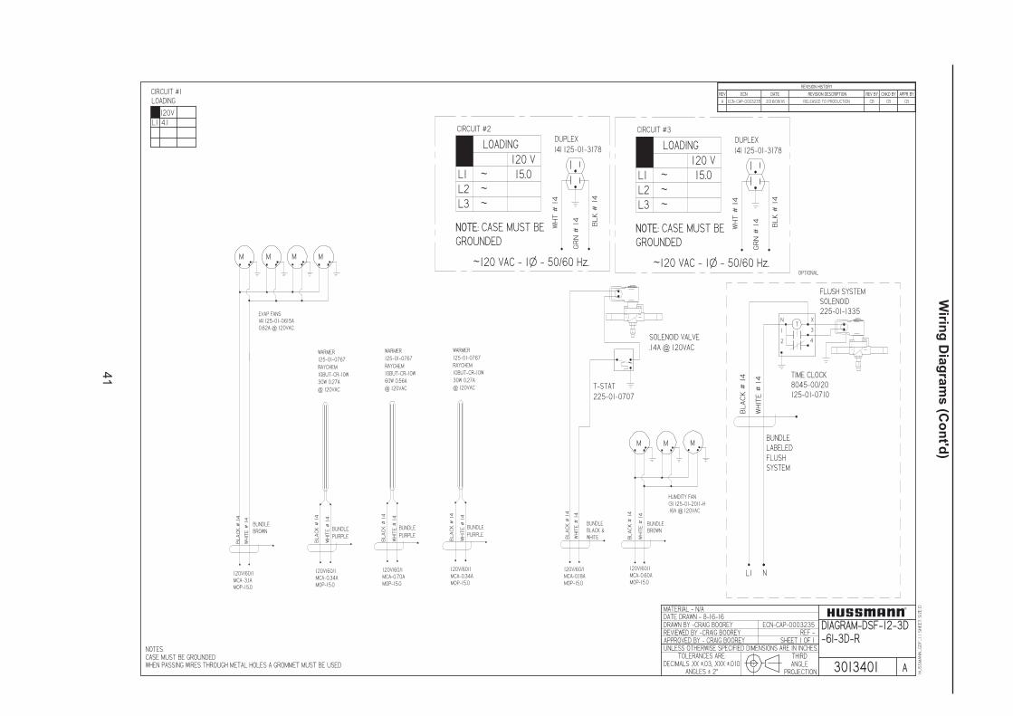
41
HUSSMANN_GDF_1.1SHEETSIZEDMATERIAL - N/A
THIRDANGLE
PROJECTION
UNLESS OTHERWISE SPECIFIED DIMENSIONS ARE IN INCHES.
DRAWN BY -CRAIG BOOREY
APPROVED BY - CRAIG BOOREY
TOLERANCES ARE:DECIMALS .XX u.03, .XXX u.010
ANGLES u 2v
DATE DRAWN - 8-16-16ECN-CAP-0003235
REVIEWED BY -CRAIG BOOREY REF -
3013401
DIAGRAM-DSF-12-3D-6I-3D-R
REV ECN DATE REVISION DESCRIPTION REV BY CHKD BY APPR BY
A ECN-CAP-0003235 2016/08/16 RELEASED TO PRODUCTION CB CB CB
REVISION HISTORY
NOTES:CASE MUST BE GROUNDEDWHEN PASSING WIRES THROUGH METAL HOLES A GROMMET MUST BE USED A
SHEET 1 OF 1
CIRCUIT #1
L1
LOADING
4.1120V
EVAP FANS(4) 125-01-0615A0.62A @ 120VAC
BUNDLEBROWN
HUMDITY FAN(3) 125-01-2011-H.16A @ 120VAC
BUNDLEBROWN
BLACK#14
WHITE#14
BLACK#14
WHITE#14
M M
TX
4
N
31
2
FLUSH SYSTEMSOLENOID225-01-1335
BUNDLELABELEDFLUSHSYSTEM
BLACK#14
WHITE#14
TIME CLOCK8045-00/20125-01-0710
L1 N
LOADING120 V
L1L2L3
~~~
15.0
NOTE: CASE MUST BEGROUNDED
CIRCUIT #2
~120 VAC - 1Ø - 50/60 Hz.
DUPLEX(4) 125-01-3178
BLK#14
WHT#14
GRN#14
LOADING120 V
L1L2L3
~~~
15.0
NOTE: CASE MUST BEGROUNDED
CIRCUIT #3
~120 VAC - 1Ø - 50/60 Hz.
DUPLEX(4) 125-01-3178
BLK#14
WHT#14
GRN#14
BLACK#14
WHITE#14
WARMER125-01-0767RAYCHEM10BUT-CR-10W30W 0.27A@ 120VAC
BUNDLEPURPLE
M M M M
OPTIONAL
BUNDLEBLACK &WHITEB
LACK#14
WHITE#14
T-STAT225-01-0707
SOLENOID VALVE.14A @ 120VAC
M
120V/60/1MCA-3.1AMOP-15.0
120V/60/1MCA-0.34AMOP-15.0
BLACK#14
WHITE#14
WARMER125-01-0767RAYCHEM10BUT-CR-10W60W 0.56A@ 120VAC
BUNDLEPURPLE
120V/60/1MCA-0.70AMOP-15.0
BLACK#14
WHITE#14
WARMER125-01-0767RAYCHEM10BUT-CR-10W30W 0.27A@ 120VAC
BUNDLEPURPLE
120V/60/1MCA-0.34AMOP-15.0
120V/60/1MCA-0.18AMOP-15.0
120V/60/1MCA-0.60AMOP-15.0
Wirin
g D
iag
ram
s (C
on
t'd)

42
HUSSMANN_GDF_1.1SHEETSIZEDMATERIAL - N/A
THIRDANGLE
PROJECTION
UNLESS OTHERWISE SPECIFIED DIMENSIONS ARE IN INCHES.
DRAWN BY -CRAIG BOOREY
APPROVED BY - CRAIG BOOREY
TOLERANCES ARE:DECIMALS .XX u.03, .XXX u.010
ANGLES u 2v
DATE DRAWN - 5-5-16ECN-CAP-0001581
REVIEWED BY -CRAIG BOOREY REF -
3005959
DIAGRAM-DSF-24-4D-6N-4D-6N-4D-R
REV ECN DATE REVISION DESCRIPTION REV BY CHKD BY APPR BY
A ECN-CAP-0001581 2016/05/05 RELEASED TO PRODUCTION CB CB CB
REVISION HISTORY
NOTES:CASE MUST BE GROUNDEDWHEN PASSING WIRES THROUGH METAL HOLES A GROMMET MUST BE USED A
SHEET 1 OF 2
CIRCUIT #1
L1
LOADING
4.5120V
EVAP FANS(4) 125-01-0615A0.62A @ 120VAC
BUNDLEBROWN BUNDLE
PURPLE
WARMER
125-01-0767
RAYCHEM
10BUT-CR-10W
60W .56A @
120VAC
HUMDITY FAN(3) 125-01-2011-H.16A @ 120VAC
BUNDLEBROWN
BLACK#14
WHITE#14
BLACK#14
WHITE#14
BLACK#14
WHITE#14
MMM M
M M
M
BLACK#14
WHITE#14
WARMER
125-01-0767
RAYCHEM
10BUT-CR-10W
30W .28A
@ 120VAC
BUNDLE
PURPLE
BLACK#14
WHITE#14
WARMER
125-01-0767
RAYCHEM
10BUT-CR-10W
40W .36A
@ 120VAC
BUNDLE
PURPLE
RELAY TYCOT92P7A22-1200459304001
CAP OFF WIRESLABEL: RELAY OUTPUTWIRESTO CASE CONTROLLER
L1 N
TX
4
N
31
2
FLUSH SYSTEMSOLENOID225-01-1335
BUNDLELABELEDFLUSHSYSTEM
BLACK#14
WHITE#14
TIME CLOCK8045-00/20125-01-0710
L1 N
CIRCUIT #1
TIMER SWITCH20 AMP1H77162550
L1
NG
RELAY (NC)MARS 90341125-01-1343
LOADING120 V
L1L2L3
~~~
15.0
NOTE: CASE MUST BEGROUNDED
CIRCUIT #3
~120 VAC - 1Ø - 50/60 Hz.
DUPLEX(4) 125-01-3178
BLK#14
WHT#14
GRN#14
LOADING120 V
L1L2L3
~~~
15.0
NOTE: CASE MUST BEGROUNDED
CIRCUIT #4
~120 VAC - 1Ø - 50/60 Hz.
DUPLEX(4) 125-01-3178
BLK#14
WHT#14
GRN#14
2 4
1 2
LIQUID LINESOLENOID125-01-1332
BUNDLEBLACK &WHITEB
LACK#14
WHITE#14
14' SECTION
Wirin
g D
iag
ram
s (C
on
t'd)

43
HUSSMANN_GDF_1.1SHEETSIZEDMATERIAL - N/A
THIRDANGLE
PROJECTION
UNLESS OTHERWISE SPECIFIED DIMENSIONS ARE IN INCHES.
DRAWN BY -CRAIG BOOREY
APPROVED BY - CRAIG BOOREY
TOLERANCES ARE:DECIMALS .XX u.03, .XXX u.010
ANGLES u 2v
DATE DRAWN - 4-5-16ECN-CAP-0000240
REVIEWED BY -CRAIG BOOREY REF -
3003378
DIAGRAM-DSF-24-10I-45O-10I-R
REV ECN DATE REVISION DESCRIPTION REV BY CHKD BY APPR BY
A ECN-CAP-0000240 2016/04/05 RELEASED TO PRODUCTION CB CB CB
REVISION HISTORY
NOTES:CASE MUST BE GROUNDEDWHEN PASSING WIRES THROUGH METAL HOLES A GROMMET MUST BE USED A
SHEET 1 OF 1
CIRCUIT #1
L1
LOADING
4.9120V
EVAP FANS(5) 125-01-0615A0.62A @ 120VAC
BUNDLEBROWN
HUMDITY FAN(2) 125-01-2011-H.16A @ 120VAC
BUNDLEBROWN
BLACK#14
WHITE#14
BLACK#14
WHITE#14
M M
BLACK#14
WHITE#14
WARMER125-01-0767RAYCHEM10BUT-CR-10W30W .28A@ 120VAC
BUNDLEPURPLE
TX
4
N
31
2
FLUSH SYSTEMSOLENOID225-01-1335
BUNDLELABELEDFLUSHSYSTEM
BLACK#14
WHITE#14
TIME CLOCK8045-00/20125-01-0710
L1N
CIRCUIT #1
TIPPETTE SWITCH125-01-0311
L1
NG
LOADING120 V
L1L2L3
~~~
15.0
NOTE: CASE MUST BEGROUNDED
CIRCUIT #2
~120 VAC - 1Ø - 50/60 Hz.
DUPLEX(4) 125-01-3178
BLK#14
WHT#14
GRN#14
LOADING120 V
L1L2L3
~~~
15.0
NOTE: CASE MUST BEGROUNDED
CIRCUIT #3
~120 VAC - 1Ø - 50/60 Hz.
DUPLEX(4) 125-01-3178
BLK#14
WHT#14
GRN#14
BUNDLEBLACK &WHITEB
LACK#14
WHITE#14
BLACK#14
WHITE#14
WARMER125-01-0767RAYCHEM10BUT-CR-10W100W 0.93A@ 120VAC
BUNDLEPURPLE
T-STAT225-01-0707
SOLENOID225-01-1332.14A @ 120VAC
M M M M M
FANS FOR WEDGE
HEATER FOR WEDGE
OPTIONAL
BUNDLEBLACK &WHITEB
LACK#14
WHITE#14
T-STAT225-01-0707
SOLENOID225-01-1332.14A @ 120VAC
SOLENOID FOR WEDGE
FAN FOR WEDGE
Wirin
g D
iag
ram
s (C
on
t'd)
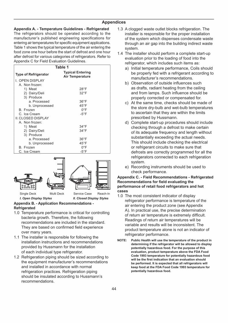
44
Appendix A. - Temperature Guidelines - Refrigerated
The refrigerators should be operated according to the
manufacturer’s published engineering specifi cations for
entering air temperatures for specifi c equipment applications.
Table 1 shows the typical temperature of the air entering the
food zone one hour before the start of defrost and one hour
after defrost for various categories of refrigerators. Refer to
Appendix C for Field Evaluation Guidelines.
Table 1
Type of RefrigeratorTypical Entering
Air Temperature
I. OPEN DISPLAY
A. Non frozen:
1) Meat 28°F
2) Dairy/Deli 32°F
3) Produce
a. Processed 36°F
b. Unprocessed 45°F
B. Frozen 0°F
C. Ice Cream -5°F
II. CLOSED DISPLAY
A. Non frozen:
1) Meat 34°F
2) Dairy/Deli 34°F
3) Produce
a. Processed 36°F
b. Unprocessed 45°F
B. Frozen 0°F
C. Ice Cream -5°F
Single Deck Multi Deck Service Case Reach-In
I. Open Display Styles II. Closed Display Styles
Appendix B. - Application Recommendations -
Refrigerated
1.0 Temperature performance is critical for controlling
bacteria growth. Therefore, the following
recommendations are included in the standard.
They are based on confi rmed fi eld experience
over many years.
1.1 The installer is responsible for following the
installation instructions and recommendations
provided by Hussmann for the installation
of each individual type refrigerator.
1.2 Refrigeration piping should be sized according to
the equipment manufacturer’s recommendations
and installed in accordance with normal
refrigeration practices. Refrigeration piping
should be insulated according to Hussmann’s
recommendations.
1.3 A clogged waste outlet blocks refrigeration. The
installer is responsible for the proper installation
of the system which dispenses condensate waste
through an air gap into the building indirect waste
system.
1.4 The installer should perform a complete start-up
evaluation prior to the loading of food into the
refrigerator, which includes such items as:
a) Initial temperature performance, Coils should
be properly fed with a refrigerant according to
manufacturer’s recommendations.
b) Observation of outside infl uences such
as drafts, radiant heating from the ceiling
and from lamps. Such infl uence should be
properly corrected or compensated for.
c) At the same time, checks should be made of
the store dry-bulb and wet-bulb temperatures
to ascertain that they are within the limits
prescribed by Hussmann.
d) Complete start-up procedures should include
checking through a defrost to make certain
of its adequate frequency and length without
substantially exceeding the actual needs.
This should include checking the electrical
or refrigerant circuits to make sure that
defrosts are correctly programmed for all the
refrigerators connected to each refrigeration
system.
e) Recording instruments should be used to
check performance.
Appendix C. - Field Recommendations - Refrigerated
Recommendations for fi eld evaluating the
performance of retail food refrigerators and hot
cases
1.0 The most consistent indicator of display
refrigerator performance is temperature of the
air entering the product zone (see Appendix
A). In practical use, the precise determination
of return air temperature is extremely diffi cult.
Readings of return air temperatures will be
variable and results will be inconsistent. The
product temperature alone is not an indicator of
refrigerator performance.
NOTE: Public Health will use the temperature of the product in
determining if the refrigerator will be allowed to display
potentially hazardous food. For the purpose of this
evaluation, product temperature above the FDA Food
Code 1993 temperature for potentially hazardous food
will be the fi rst indication that an evaluation should
be performed. It is expected that all refrigerators will
keep food at the FDA Food Code 1993 temperature for
potentially hazardous food.
Appendices

45
1.1 The following recommendations are made
for the purpose of arriving at easily taken and
understood data which, coupled with other
observations, may be used to determine whether
a display refrigerator is working as intended:
a) INSTRUMENT - A stainless steel stem-type
thermometer is recommended and it should
have a dial a minimum of 1 inch internal
diameter. A test thermometer scaled only
in Celsius or dually scaled in Celsius and
Fahrenheit shall be accurate to 1°C (1.8°F).
Temperature measuring devices that are
scaled only in Fahrenheit shall be accurate to
2°F. The thermometer should be checked for
proper calibration. (It should read 32°F when
the stem is immersed in an ice water bath).
b) LOCATION - The probe or sensing element
of the thermometer should be located in
the airstream where the air fi rst enters the
display or storage area, and not more than
1 inch away from the surface and in the
center of the discharge opening.
c) READING - It should fi rst be determined
that the refrigerator is refrigerating and has
operated at least one hour since the end
of the last defrost period. The thermometer
reading should be made only after it has
been allowed to stabilize, i.e., maintain a
constant reading.
d) OTHER OBSERVATIONS - Other
observations should be made which may
indicate operating problems, such as
unsatisfactory product, feel/appearance.
e) CONCLUSIONS - In the absence of any
apparent undesirable conditions, the
refrigerator should be judged to be operating
properly. If it is determined that such
condition is undesirable, i.e., the product is
above proper temperature, checks should be
made for the following:
1. Has the refrigerator been loaded with
warm product?
2. Is the product loaded beyond the “Safe
Load Line” markers?
3. Are the return air ducts blocked?
4. Are the entering air ducts blocked?
5. Is a dumped display causing turbulent air
fl ow and mixing with room air?
6. Are spotlights or other high intensity
lighting directed onto the product?
7. Are there unusual draft conditions (from
heating/air-conditioning ducts, open
doors, etc.)?
8. Is there exposure to direct sunlight?
9. Are display signs blocking or diverting
airfl ow?
10. Are the coils of the refrigerator iced up?
11. Is the store ambient over 75°F, 55% RH
as set forth in ASHRAE Standard 72 and
ASHRAE Standard 117?
12. Are the shelf positions, number, and size
other than recommended by Hussmann?
13. Is there an improper application or control
system?
14. Is the evaporator fan motor/blade
inoperative?
15. Is the defrost time excessive?
16. Is the defrost termination, thermostat
(if used) set too high?
17. Are the refrigerant controls incorrectly
adjusted?
18. Is the air entering the condenser above
design conditions? Are the condenser fi ns
clear of dirt, dust, etc.?
19. Is there a shortage of refrigerant?
20. Has the equipment been modifi ed
to use replacements for CFC-12,
CFC-502 or other refrigerant? If so,
have the modifi cations been made in
accordance with the recommendations
of the equipment manufacturer? Is the
refrigerator charged with the proper
refrigerant and lubricant? Does the system
use the recommended compressor?
Appendix D. - Recommendations to User -
Refrigerated
1.0 Hussmann Corporation provides instructions
and recommendations for proper periodic
cleaning. The user will be responsible for
such cleaning, including the cleaning of low
temperature equipment within the compartment
and the cooling coil area(s). Cleaning practices,
particularly with respect to proper refrigerator
unloading and warm-up, must be in accordance
with applicable recommendations.
Appendices (Cont'd)
46
1.1 Cleaning of non frozen food equipment
should include a weekly cleaning of the food
compartment as a minimum to prevent bacteria
growth from accumulating. Actual use and
products may dictate more frequent cleaning.
Circumstances of use and equipment design
must also dictate the frequency of cleaning the
display areas. Weekly washing down of the
storage compartment is also recommended,
especially for equipment subject to drippage
of milk or other liquids, or the collection of
vegetable, meat, crumbs, etc. or other debris
or litter. Daily cleaning of the external areas
surrounding the storage or display compartments
with detergent and water will keep the equipment
presentable and prevent grime buildup.
1.2 Load levels as defi ned by the manufacturer must
be observed.
1.3 The best preservation is achieved by following
these rules:
a) Buy quality products.
b) Receive perishables from transit equipment
at the ideal temperature for the particular
product.
c) Expedite perishables to the store’s storage
equipment to avoid unnecessary warm-up
and prolonged temperature recovery. Food
store refrigerators are not food chillers nor
can they reclaim quality lost through previous
mishandling.
d) Care must be taken when cross
merchandising products to ensure that
potentially hazardous vegetable products are
not placed in non refrigerated areas.
e) Display and storage equipment doors should
be kept closed during periods of inactivity.
f) Minimize the transfer time of perishables
from storage to display.
g) Keep meat under refrigeration in meat cutting
and processing area except for the few
moments it is being handled in processing.
When a cut or tray of meat is not to be
worked on immediately, the procedure should
call for returning it to refrigeration.
h) Keep tools clean and sanitized. Since
mechanical equipment is used for fresh
meat processing, all such equipment should
be cleaned at least daily and each time
a different kind of meat product comes in
contact with the tool or equipment.
i) Make sure that all refrigeration equipment is
installed and adjusted in strict accordance
with the manufacturer’s recommendations.
j) See that all storage and refrigeration
equipment is kept in proper working order by
routine maintenance.
Appendices (Cont'd)
For further technical information, please log on to http://www.hussmann.com/products/DSF.htm

47
The MODEL NAME and SERIAL NUMBER is required in order to
provide you with the correct parts and information for your particular
unit.
They can be found on a small metal plate on the unit.
Please note them below for future reference.
MODEL:
SERIAL NUMBER:
/ChinoAdditional copies of this publication may be obtained by contacting:
Hussmann® Chino
13770 Ramona Avenue • Chino, California 91710
(909) 628-8942 FAX
(909) 590-4910
(800) 395-9229
Service Record
Last service date: By:
_______________ __________________________________________________________________________________________________
_______________ __________________________________________________________________________________________________
_______________ __________________________________________________________________________________________________
_______________ __________________________________________________________________________________________________
_______________ __________________________________________________________________________________________________
_______________ __________________________________________________________________________________________________
_______________ __________________________________________________________________________________________________