e no surveying and civil engineering materials · pdf file1 surveying and civil engineering...
TRANSCRIPT

TABLE OF CONTENTS
S.NO TITLE PAGE
NO1 SURVEYING AND CIVIL ENGINEERING MATERIALS 1
1.1Surveying 1
1.1.1object of surveying 1
1.1.2 Primary divisions of surveying 1
1.1.3 Principle of surveying 1
1.1.4 Classification of surveying: 2
1.1.4.1 Instruments used for chain surveying: 2
1.1.4.2 Principle of Chain Surveying 3
1.1.4.3Advantages and Disadvantages of chain surveying 4
1.1.5Calculation of Areas from offsets to a Base line 4
1.1.6 Compass survey 5
1.1.6.1 Methods of using prismatic compass 6
1.1.1.6.2 bearing of line 6
1.1.6.3Designation of bearing 7
1.1.6.4Fore bearing and back bearing 7
1.1.7 Theodolite survey 8
1.1.8 Leveling 9
1.1.8.1 Principle of leveling 10
1.1.8.2 reduction level 10
1.1.9.1Methods of plane table survey 11

1.1.10 Stones 11
1.1.2 Properties of Stones 13
1.1.10.2 Requirements of Good Building Stones 14
1.1.10.3 Tests on Stones 15
1.1.10.4 Uses of stones 15
1.1.11Bricks 16
1.1.11.1 Properties of Bricks 16
1.1.11.2 Tests on Bricks 18
1.1.11.3 Classification of Bricks Based on their Quality 20
1.1.11.4 Uses of Bricks 20
1.1.12Cement 20
1.1.12.1 Types of Cement 21
1.1.12.2 Properties of Ordinary Portland Cement 22
1.1.12.3 Uses of cement 23
1.1.13 Sand 23
1.1.13Plain concrete 24
1.1.13.1 Properties if green concrete 25
1.1.13.2 Tests on Concrete 26
1.1.14Ferroumetal
31
2 BUILDING COMPONENTS AND STRUCTURES 32
2.1 Introduction 32

2.1.1Elementsofb u i l d in g
32
2.1.1.2 Basic requirements of a building 35
2 .1.1..3 Planning 36
2.1.1.5 Planning for energy efficiency 39
2.1.1.6 Planning for suitable utility 39
2.1.1.7 Planning for meeting other requirements 40
2.2 C o n v e n t i o n a l spread footings 40
2.2.2 R.C.C. footings 41
2.2.2.1 Grillage footing 44
2.2.3 Arch foundation 45
2.2.4 Pile foundations 45
.2.2.5 Stone masonry 48
2.6Brickmasonry
51
2.7 Beams 54
2.8 Columns 55
2.9 Lintels 57
3.0 Flooring 59
3.1Upper floor 61
3.1.1 Roof Coverings for Pitched 70
3.1.1 Roof Coverings for Pitched 70
3.2 Plastering 72

3.3 Stress and strain 72
3.3.1Types of stresses and strains 72
3.4 Elasticity 74
3.4.1Elastic limit 74
3.4.2Hooke’s law 74
3.4.3Young’s Modulus 74
3.4.4 Shear modulus 74
3.4.5 Bulk Modulus 74
3.4.6 Poisson’s ratio 74
3.4.7 Relation between elastic constants 75
3.4.8 Factor of safety 75
3.5 Bridges 76
3.5.1 Classification of bridges 75
5 3.5.2 Component parts of a bridge 77
5 3.6 Dams 80
3.6.1 Introduction 80
3.6.2 Purpose of a dam 80
3.6.3 Factors governing selection of site for dam 81
3.6.4 Classification of dams 83
3.7 Basics of interior design86

UNIT 3 POWER PLANT ENGINEERING3.1 Classification Of Power Plants 893.2 Layout Of Steam Power Plant 893.2.1 Coal And Ash Circuit 893.2.2 Air And Flue Gas Circuit 903.2.3 Water And Steam Circuit 913.2.4 Cooling Water Circuit 913.3 Selection Of Site For Thermal Power Plan 933.4 Gas Power Plant 943.5 Diesel Power Plant 973.5.1 Working Of Diesel Power Plant: 973.5.2 Main Components Of A Diesel 983.6 Hydro Electric Power Plant 983.6.1 Components Of Hydro Electric Power Plant 983.6.2 Working Principle Of Hydro Electric Power Plant 1003.6.3 Classification Of Hydro Electric Power Plant 1013.7 Nuclear Power Plant 1023.7.1 Components Of Nuclear Power Plant 1043.7.2 Working Principle Of Nuclear Power Plant 1053.8 Pumps 1063.8.1 Classification Of Pumps 1073.8.2 Reciprocating Pumps 1073.8.3 Working Of Single Acting Reciprocating Pump 1073.8.4 Double Acting Reciprocating Pump 1073.9 Air Vessels 1083.9.1 purpose Of Using An Air Vessel 1083.10 Centrifugal Pumps 1093.10.1 Components Of Centrifugal Pump 1093.10.2 Working Principle Of Centrifugal Pump 1093.11 Impulse Turbine 1123.12 Reaction Turbine 1123.12.1 Comparision Between Impulse And Reaction Turbine 112
UNIT 4 INTERNAL COMBUSTION ENGINES4.1 Introduction 1134.2 Classification Of Heat Engines 1134.3 Main Components Of IC Engines 1134.4 Main Components Of IC Engine 1164.5 Petrol Engines 1184.5.1 Two Stroke Cycle Petrol Engines 1194.5.2 Two Stroke Cycle Diesel Engines- Construction 1204.5.3 Four Stroke Cycle Petrol Engines 1224.5.4 Four Stroke Diesel Engine 1224.6 Scavenging 1234.7 Comparison Between Si And Ci Engines (General 123
Comparison)4.8 Comparison Between Si And Ci Engines (Merits And 123
Demerits)4.9 Comparison Between Four Stroke Cycle And Two Stroke 124
Cycle Engine (Merits And Demerits)4.10 Comparison Between Four Stroke Cycle And Two Stroke 125
Cycle Engine (Merits And Demerits)4.11 I.C Engine Terminolgogy 125
4.11.1 Major Parts Of An Ic Engine 1264.12 Steam Boilers 1274.12.1 Fire Tube & Water Tube Boilers 1274.12.2 Internally Fired Boiler 1284.12.3 Externally Fired Boiler 1294.12.4 Cochran Boiler 1294.12.5 Lamont Boiler 1304.13 Boiler Mountings & Accessories 1304.14 Boiler Accessories 1314.15 Differences Between Boiler Mountings And Accessories: 134
UNIT 5 REFRIGERATION AND AIRCONDITIONING5.1 Refrigeration 1375.2 Vapour Compression Refrigeration System 1385.3 Vapour Absorption Refrigeration System 1405.4 Comparison Between Vapour Compression & Vapour 140
Absorption Refrigeration Systems5.5 Air Conditioning 1435.6 Classification Of Air Conditioning 1435.7 Window Type Air Conditioner 144
Question Bank 147University question 154

GE6251 BASIC CIVIL AND MECHANICAL ENGINEERING L T P C4 0 0 4
A – CIVIL ENGINEERINGUNIT I SURVEYING AND CIVIL ENGINEERING MATERIALS 15Surveying: Objects – types – classification – principles – measurements of distances –angles –leveling – determination of areas – illustrative examples.Civil Engineering Materials: Bricks – stones – sand – cement – concrete – steelsections.UNIT II BUILDING COMPONENTS AND STRUCTURES 15Foundations: Types, Bearing capacity – Requirement of good foundations.Superstructure: Brick masonry – stone masonry – beams – columns – lintels – roofing– flooring –plastering – Mechanics – Internal and external forces – stress – strain – elasticity –Types of Bridgesand Dams – Basics of Interior Design and Landscaping.TOTAL: 30 PERIODSB – MECHANICAL ENGINEERINGUNIT III POWER PLANT ENGINEERING 10Introduction, Classification of Power Plants – Working principle of steam, Gas, Diesel,Hydro-electricand Nuclear Power plants – Merits and Demerits – Pumps and turbines – workingprinciple ofReciprocating pumps (single acting and double acting) – Centrifugal Pump.UNIT IV IC ENGINES 10Internal combustion engines as automobile power plant – Working principle of Petrol andDieselEngines – Four stroke and two stroke cycles – Comparison of four stroke and two strokeengines –Boiler as a power plant.UNIT V REFRIGERATION AND AIR CONDITIONING SYSTEM 10Terminology of Refrigeration and Air Conditioning. Principle of vapour compression andabsorptionsystem – Layout of typical domestic refrigerator – Window and Split type room Airconditioner.
TOTAL: 30 PERIODSREFERENCES:1. Shanmugam G and Palanichamy M S, “Basic Civil and Mechanical Engineering”, TataMcGrawHill Publishing Co., New Delhi, (1996).2. Ramamrutham S., “Basic Civil Engineering”, Dhanpat Rai Publishing Co. (P) Ltd.(1999).3. Seetharaman S., “Basic Civil Engineering”, Anuradha Agencies, (2005).4. Venugopal K. and Prahu Raja V., “Basic Mechanical Engineering”, AnuradhaPublishers,Kumbakonam, (2000).5. Shantha Kumar S R J., “Basic Mechanical Engineering”, Hi-tech Publications, Mayil

GE6251 BASIC CIVIL AND MECHANICAL ENGINEERING
SCE Page 1 DEPARTMENT OF CIVIL ENGINEERING
UNIT ISURVEYING AND CIVIL ENGINEERING MATERIALS
Surveying: Objects – types – classification – principles – measurements of distances –angles –leveling – determination of areas – illustrative examples.Civil Engineering Materials: Bricks – stones – sand – cement – concrete – steel sections
1.1SurveyingSurveying is the art of determining the relative position of points on above or beneath
the surface of the earth by means of direct or indirect measurements of distances, directionand elevation.1.1.1object of surveying
The primary object of a survey is the preparation of a plan map. the results ofsurveys when plotted and drawn on paper, constitute a plan. Therefore a plan is arepresentation of the ground and the objects upon it some scale as projected on a horizontalplane. If the scale is large, then it is called a plan. if the scale is small, then it is called amap. Example: a plan of a building, a map of India.Purposes of surveyFollowing are some of the purposes of survey: To prepare archeological maps, geological maps, military maps etc. To establish boundary points of properties with reference to the available records
and demarcate ownership. To measure quantities in cutting or in embankments using contour maps. To lay out th alignment of engineering structures such as roads, railways etc. To plot profile of a structure(eg. irrigation canal) for ascertaining the carrying
capacity of canal, capacity of reservoir etc To determine the relative position of desired points with reference to a known bench
mark (eg. position of hill stations with reference to mean sea level). To measure distance between various points (eg. distance between two cities).
1.1.2 Primary divisions of surveyingSurvey may be primarily divided into following two divisions. Plane surveying: in plane surveying, the mean surface of the earth is considered as a
plane and the spheroid shape is neglected as the surveys extend over small areas. Geodetic surveying: in geodetic surveying, the curvature of earth is taken into
account and all lying in the surface are curved lines and the triangles are sphericaltriangles, since large distances and areas are covered.
1.1.3 Principle of surveyingAll surveys are based on two fundamental principles they are: Working from whole to part: in order to prevent accumulation of errors and to
localize the minor errors, a set of primary central points are established first withhigher precision in and around the area to be surveyed. Later on, in between thoseprimary control points, inner control points are established with less precisionmethod. The details are surveyed with the help of these inner control points,adopting any one method of surveying. This principles is known as working fromwhole to part.
Fixing a point with reference to two fixed points: suppose points 'A'and'B'are knownon the distance between them is measured

GE6251 BASIC CIVIL AND MECHANICAL ENGINEERING
SCE Page 2 DEPARTMENT OF CIVIL ENGINEERING
. Let it be required to locate or mark a point 'C'. The relative position of the point Cis located with reference to the two fixed points A and B by one of the followingmethods.
a) Liner measurementb) Angular measurementc) Both liner and angular measurements
1.1.4 Classification of surveying:According to the instruments used, the surveying is classifieds follows: chain surveying compass surveying theodolite surveying plane table surveying tachometric surveying etc.
1.1.4.1 Instruments used for chain surveying:The various instruments used in chain surveying are as follows. chain arrows pegs ranging rods offset rods plumb bob
1. Chain:Chains are used to measure horizontal distances. Chains are formed of straight links of
galvanized mild steel wire called links. The ends of each link are bent into a loop handconnected together by means of three oval rings which afford flexibility to the chain.
The chain s made of mind steel. The ends of the chin are provided with brasshandles for dragging the chain on the ground. the outside of the handle is the zero point orthe end point of the chain and the length of the chain measured from the outside of onehandle to the outside of the other. The length of a link is the distance between the centers ofthe two consecutive middle rings.

GE6251 BASIC CIVIL AND MECHANICAL ENGINEERING
SCE Page 3 DEPARTMENT OF CIVIL ENGINEERING
The end links include the handles. Metallic tags are indicators of the chain to facilitatequick reading of fraction of a chain in surveying measurements. Metric survey chains areavailable in lengths of 20m and 30m. The 20m chain contains 100 links whereas 30m.Chain contains 150 links. One link of both the type of chain measure 20cm.
2. Arrows:Arrows or making pins are made of tempered steel wire 4mm in diameter and generally 10arrows are supplied with a chain. An arrow is inserted into the ground after the chain lengthis measured on the ground. Usually the length of an arrow is 40cm and one end of it ismade sharp and the other end is bent into a circle for facility of carrying.
3. Pegs:Wooden pegs are used to mark the positions of the stations terminal points of a survey line.
They are made of hard timber, generally 2.5cm or 3 cm square and 15cm long, tapered atthe end.
4. Ranging RodsThe ranging rods are used for making the positions of stations and for ranging the lines.They are made of ell seasoned straight grained timber teak. They circular in cross section of3cm diameter and have a length of either 2 or 3cm, lengh being more common. They areshod at the bottom with a heavy iron points. In order to make them visible at a distance,they are pained alternatively black and white or red and white.
5. OffsetOffset rod is similar to that of ranging rod. They are should with pointed iron shoe at oneend, ad provided with a notch or a hook at the other for pulling or pushing the chain througha hedges or other obstructions.
6. Plumb BobWhile chaining along sloping ground, a plump is required to transfer the points to theground. It is also used for accurate centering of the theodolite compass, plane table etc overa station mark and for testing the vertically of ranging poles
7. Cross staffThis is the instrument used for setting out right angles to a chain line. It consists of either aframe or box with two pairs of vertical slits and is mounted on a pole shod for fixing in theground Open cross staff French cross staff Adjustable cross staff
1.1.4.2 Principle of Chain SurveyingThe rectangle is the simplest fig that can be plotted from the lengths of its sided. Based onthis, the principle of chain surveying is to divide the area to be surveyed into a network ofconnected triangles. Hence chain surveying is some times called chain triangulation. Theexact arrangement of triangles to be adopted depends upon the shape and configuration ofthe ground and obstacles met with. When it contains no angle smaller than 30degree greaterthan 120 degree.
GE6251 BASIC CIVIL AND MECHANICAL ENGINEERING
SCE Page 4 DEPARTMENT OF CIVIL ENGINEERING
1.1.4.3Advantages and Disadvantages of chain surveyingAdvantages: Chain surveying is suitable for fairly level ground It does not require costly equipments It is used for preparing plans of smaller area It is simple
Disadvantages It is cannot used for large areas It is not always accurate
1.1.5Calculation of Areas from offsets to a Base lineThe area may be calculated by the rule: Mid-ordinate Rule Average ordinate Rule Trapezoidal rule Simpson’s Rule
1.Mid-ordinate rule:
Area = (O1+O2+……….+on)dO1, O2 = the ordinates at the mid points of each divisionn = number of divisionsL = Length of base line= ndd = Distance of each division
2.Average ordinate Rule
Area = ((O1+O2+……On)/(n+1))LO1, O2….= Ordinates at the end of each division
3. Trapezoidal Rule
Area= (((O0+On)/2)+(O0+O2+……On-1))d
4. Simpson’s Rule
Area = ((d/3) x ((O0+On+4(O1+O3+On-1)+2(O2+O4+….+On-2))
Example: 1The following perpendicular offsets were taken at 10 meter intervals from a survey lineto an irregular boundary line.3.15m, 4.3m, 8.2m, 5.6m, 6.85m, 7.6m, 4.2m, 5.6m, 4.3mCalculate the area enclosed between the survey line, the irregular boundary line, andfirst and last offsets, by the application ofa) Average ordinate ruleb) Trapezoidal rulec) Simpson’s rule

GE6251 BASIC CIVIL AND MECHANICAL ENGINEERING
SCE Page 5 DEPARTMENT OF CIVIL ENGINEERING
Averaged = the interval between the offset = 10 mn = number of divisions = 8n+1 = number of ordinates = 8+1 =9L= Length of the base line = 8 x 10 = 80m
a) Average ordinate rule
Area = ((O1+O2+……On)/(n+1))LO1, O2….= Ordinates at the end of each division
Area = (( 3.15 + 4.3 + 8.2+ 5.6 + 6.85 + 7.6 + 4.2 + 5.6 + 4.3 )/(8+1)) x 80=442.66m2
b) Trapezoidal rule
Area= (((O0+On)/2)+(O0+O2+……On-1))d
Area = (3.725 + 42.35) x10 =460.75m2
c) Simpson’s rule
Area= 10/3(7.45 +92.4 +38.5) = 461.167m2
1.1.6 Compass survey
When the area to be surveyed is large, chain and compass surveying is preferable. Acompass is used to measure the magnetic bearing of a line. There are two forms of compassthat are commonly used. 1. The prismatic compass and 2. The surveyors’ compass.
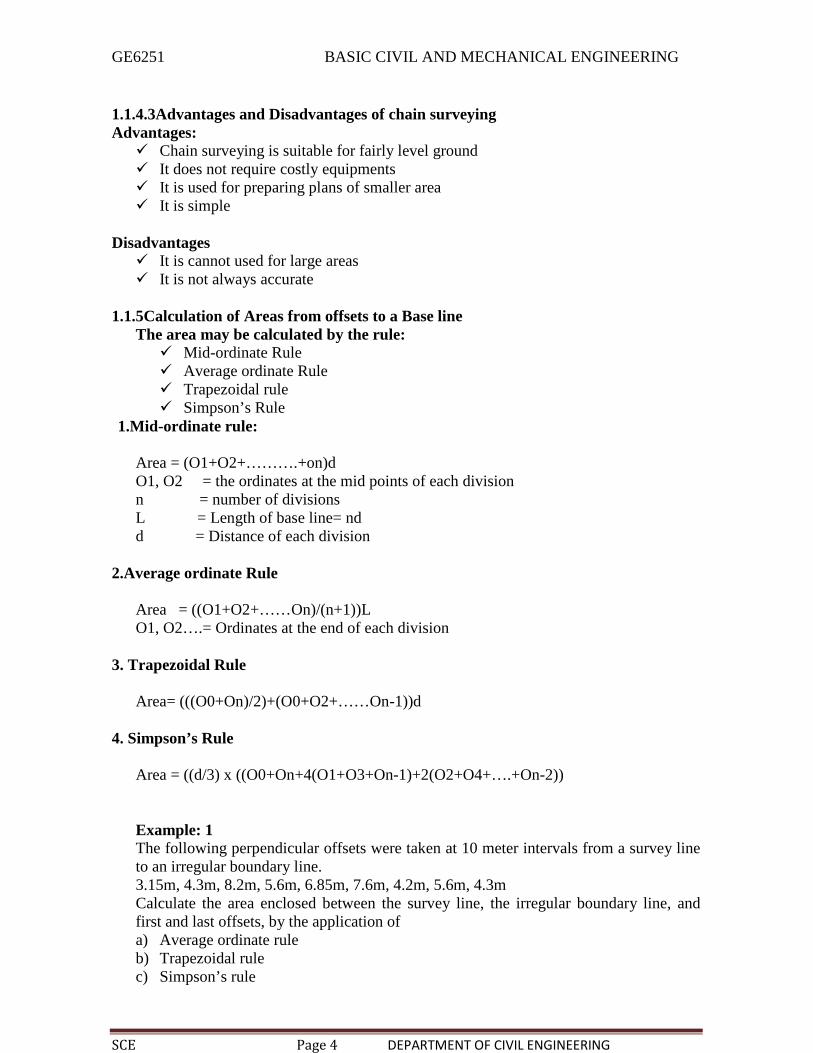
1. The prismatic compass: It is circular in shape and its diameter varies from 85 mm to110 mm. A pivot is provided at the centre of the box. It carries a magnetic needle. Theneedle is attached to an aluminum ring which is graduated to 1/2. A light spring break isattached to the inside of the base to damp the oscillations of the needle and bring it to restbefore taking a reading.
A reflecting prism facilitates reading of the angles and is protected from moisture anddust etc by a prism cap. The prism base and vertical facts are made convex which magnifiesthe readings. the object vane is located diametrically opposite to the prism. It is hinged tothe side of the box and carries a horse hair. A title reflecting mirror is provided on the sideof the object vane to enable bearing of very high or low objects to be taken. A metal coveris provided to enclose the compass and the object vane.
GE6251 BASIC CIVIL AND MECHANICAL ENGINEERING
SCE Page 6 DEPARTMENT OF CIVIL ENGINEERING
2. Surveyor’s compass: Surveyor’s compass resembles the prismatic compass but with aslight difference. The graduated card is attached to the box and North 90 at south and atEast and West interchanged
1.1.6.1 Methods of using prismatic compass
The compass is usually mounted on a light tripod which carries a vertical spindle in a balland socket joint which the box is screwed. By means of this arrangement, the instrumentcan be quickly leveled and also rotated in a horizontal plane and clamped in any position.Centering: The compass should be centered over the station where the bearing is to be
taken. This is done by dropping a small piece of stone from the centre of the compass sothat it falls on the top of the peg marking the station (or by using plumb bob) and byadjusting the legs of the tripod.
Leveling : The compass should then be leveled by eye, by means of a ball and socket jointso that the graduated ring may swing quite freely. It should be clamped when leveled.Observing Bearing: A ranging rod is kept at the next station.The compass is turned until the ranging rod at the station is bisected by the hair when
looked through the slit above the prism.When the needle comes to rest, by pressing the knob if necessary, the reading is noted atwhich the hair line appears to out the image of the graduated ring. The sighting og theranging rod and the reading is done simultaneously. The reading gives the bearing of theline.1.1.6.2 bearing of line:
The bearing of a line is the horizontal angle made by the line with a selected reference linecalled the meridian. There are two types of bearings.i) Magnetic Bearing: The direction indicated by a freely supported magnetic needle
unaffected by local attractive forces, is called the magnetic meridian. The angle betweenany line and magnetic meridian is called magnetic bearing or simply bearing.
ii) The Bearing: The line joining the geographical north and south poles is known as the

GE6251 BASIC CIVIL AND MECHANICAL ENGINEERING
SCE Page 7 DEPARTMENT OF CIVIL ENGINEERING
true meridian or geographical meridian. The angle between any line and the true meridian iscalled true bearing of azimuth.
1.1.6.3DESIGNATION OF BEARING
The whole circle bearing system Quadrantal bearing system, or reduced bearing system
The whole circle bearing system:In this system the bearing of a line is measured with north in clockwise direction. Thevalue of the bearing thus varies from 0o to 360o. Quadrantal bearing system
In this system the bearing of a line measured from either the north or the south,clockwise or counter clockwise whichever is nearer the line, towards the east or west
1.1.6.4Fore bearing and back bearingIn compass surveying, two bearings are observed for each line, one from each end of theline. The bearing of a line in the direction of the progress of survey is called fore bearingwhile the bearing measured in the opposite direction is known as back bearing. For e.g. thebearing of line AB taken from the point A is the fore bearing of ine AB and the bearingfrom point B is back bearing of the line AB.

GE6251 BASIC CIVIL AND MECHANICAL ENGINEERING
SCE Page 8 DEPARTMENT OF CIVIL ENGINEERING
1.1.7 Theodolite survey
The theodolite is the most precise instrument used for measurement of horizontal andvertical angles. It can also be used for various surveying operations such as establishinggrades, setting out curves, extending survey lines, determining differences in elevation etc.Two categories classified: Transit theodolite Non-transit thedolite
Essential parts of a transit theodolite
Telescope:A thedolite is provided with a telescope to sight the distant objects clearly. It is mounted ona spindle known as horizontal axisTwo spindles:There are two spindles with axes one inside the other. The outer axis is hallowed and itsinterior is ground conical to fit the central vertical axis which is a solid and conical.Lower plate:The outer axis is attached to the lower plate also called the scale plate, having its edgebeveled. The edge is silvered and graduated form Oo to 360o in the clockwise direction.The lower plate is provided with a clamped tangent screw or the slow motion screw bymeans of which it can be fixed at any desired positionUpper plate:The upper plate also called the vernier plate is attached to the inner axis. A clamp and atangent or slow motion screw are provided for the purpose of accurately fixing the vernierplate to the scale plate. When both plates are clamped together and the lower clamp orloosened, the instrument can be rotated about its outer axis; while if lower plate be clampedand the vernier plate be loosened, the instrument can be rotated about the inner axis. Beforeeither of the tangent screw is turned, the corresponding clamp must be tightened.Level Tubes:Two spirit levels called placed at right angles to each other are fixed on the upper surface ofthe venires plate for leveling in the instrument.
GE6251 BASIC CIVIL AND MECHANICAL ENGINEERING
SCE Page 9 DEPARTMENT OF CIVIL ENGINEERING
Vertical circle:The vertical circle and graduated and is attached to the horizontal axis of the telescope andthus it rotates with the telescope. The circle is graduated either continuous from Oo to 90o.By means of vertical clamp and tangential screw, the telescope can be set accurately at anyposition in vertical plane.
1.1.8 Levelling
Levelling may be defined as the art of determining the relative height or elevants of pointsor objects on the earth’s surface.
Instruments used for leveling: Level Levelling Staff
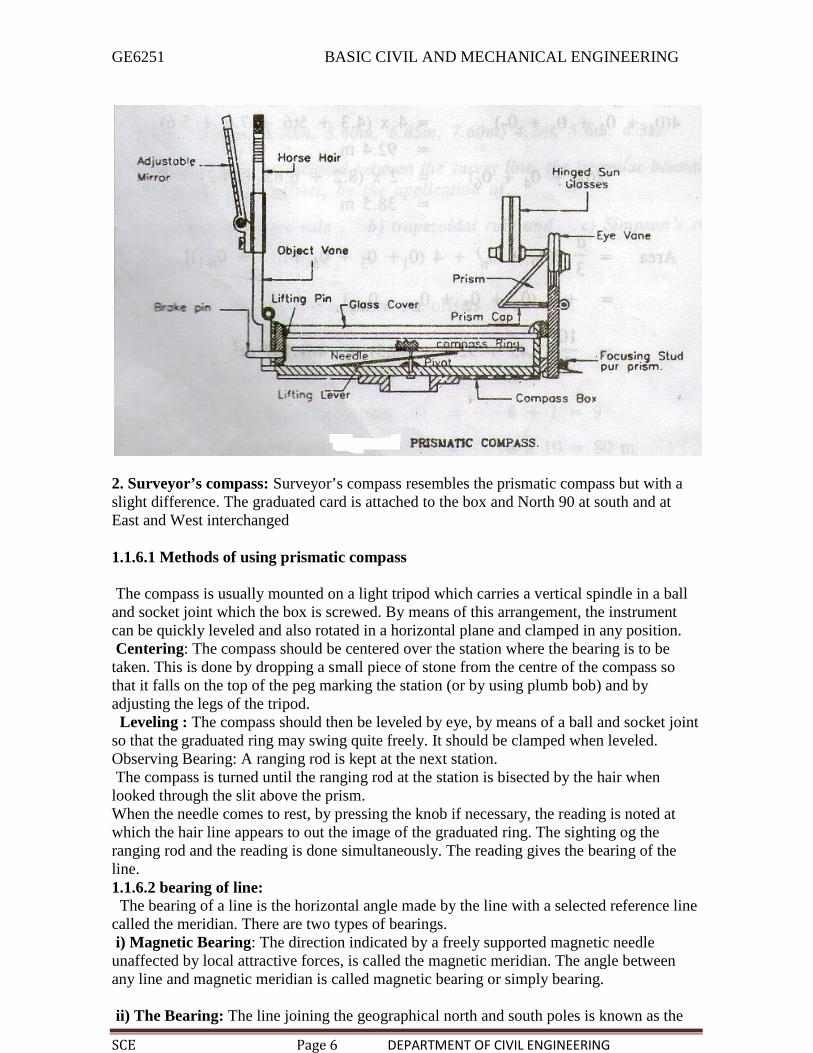
Level: The purpose of a level is to provide a horizontal line of sight.
Parts: A telescope to provide line of sight A level tube to make the line of sight horizontal A leveling head to bring the bubble in its centre of run A tripod to support the instrument
Dumpy level:The telescope is rigidly fixed with the support and therefore, can neither be rotated aboutthe longitudinal axis, nor can it be removed from its support. A long bubble tube is attachedto the top of the telescope. The leveling head generally consists of two parallel plates witheither three foot screws of four foot screws. The upper plate is known as tribrach and thelower plate is known as trivet which can be screwed on a tripod

GE6251 BASIC CIVIL AND MECHANICAL ENGINEERING
SCE Page 10 DEPARTMENT OF CIVIL ENGINEERING
Levelling staff:
A leveling Staff is a straight rectangular rod having graduations, the foot of the staffrepresenting zero reading. There are various type of graduated staff available and only onetype is described here.Folding type of 4m Levelling Staff:It consists of two wooden pieces each of 2m of length with the joint assembly. Thethickness and width of staff are respectively 18m and 75mm. The folding joint is of thedetachable type with locking device at the back.
Hence the stad can be made into two parts for easy handling. When two pieces are lockedtogether, the two pieces form a straight rigid leveling staff of length equal to 4m.
1.1.8.1 Principle of levelingWhen the level is set up correctly and leveled the line of collimation will be horizontaltelescope is rotated about is its vertical axis it will revolve in a horizontal plane known asthe plane of collimation and therefore, all staffs readings taken with the will be the verticalmeasurements made downwards from this plane.To find by how much amount the line of sight is above the bench mark and To ascertain byhow much amount the next point is below or above theline sight. Height of instrument= Elevation of B.M + Back sightElevation of pt B = Height of instrument – Foresight
1.1.8.2 reduction levelHeight of instrument methodIn this method, the height of instrument is calculated for ach setting of instruct, and then theelevation or reduced level of the turning point is calculated with respect to the height ofinstrumentRise and fall method:In rise and fall method the difference of level between consequence point is foundcomparing staff readings on the two points of same setting of the instrument
1.1.9 Plane table surveyPlane table survey is that type of survey in which the measurement of survey lines of thetransverse a of the transverse and their plotting to a suitable scale are done simultaneouslyon the field.It consists of: Drawing Board mounted on a tripod Aliade
Drawing board:The drawing board is mad of well seasoned wood such as teak and its size varies from400mm x 300mm to 750mm x 600 mm. the board is mounted on a tripod with ball andsocket arrangement which allow the board to be leveled and roatated about the vertical axis.Alidades:The open slight alidadeThe telescope alidade

GE6251 BASIC CIVIL AND MECHANICAL ENGINEERING
SCE Page 11 DEPARTMENT OF CIVIL ENGINEERING
The open slight alidade consists of a flat rectangular piece ofwood of about, 25mm width,12.5mm thickness and length varying from 200 to 500 mm The leveled edge of the alidadeis called finducial edge. Its edge is graduated and serves as a scale. Vertical sight vanes aremounted at both ends. One of the sight vanes is proved with a narrow slit and the other witha central vertical wire. The line of sight is in the same vertical plane as the finducial edgeThe telescope aliadade consists of a telescope mounted on a horizontal axis the ends ofwhich are supported on standards. A circular level or two spirit levels are attached to thebase of the telescope to level the plane table.
Working operations Fixing Setting Levelling Orientation
FixingFixing the table to the tripod standSettingThe table is set up at a convenient height say 1m above ground. The legs of the stand arespread apart and firmly fixed into the ground. The table is then centered. This means thatthe point plotted on the sheet corresponding to the station occupied should be exactly abovethe station on the ground. This is done by means of the plumbing fork.LevellingThe table is then leveled either by ordinarly tilting the board or by ball and socketarrangement.Orientation:Orientation is the process of putting the plane table into some fixed direction so that linerepresenting a certain direction on the drawing sheet is paralle to that direction on theground.Two methods adopted:Orientation by magnetic needleOrientation by back sighting
1.1.9.1Methods of plane table survey Radiation Intersection Traversing Resection
1.1.10 Stones
Stones, bricks, cement, lime and timber are the traditional materials used for civilengineering constructions for several centuries. In this chapter types, properties, tests anduses of these materials is explained.Stone is a ‘naturally available building material’ which has been used from the early age
of civilization. It is available in the form of rocks, which is cut to required size and shapeand used as building block. It has been used to construct small residential buildings tolarge palaces and temples all over the world. Red Fort, Taj Mahal, Vidhan Sabha atBangalore and several palaces of medieval age all over India are the famous stonebuildings.
GE6251 BASIC CIVIL AND MECHANICAL ENGINEERING
SCE Page 12 DEPARTMENT OF CIVIL ENGINEERING
1.1.10.1Type ofStones
Stones used for civil engineering works may be classified in the followingthree ways:
Geological Physical Chemical
Gelogical classficationBased on their origin of formation stones are classified into three main groups—Igneous,sedimentary and metamorphic rocks.
(i) Igneous Rocks: These rocks are formed by cooling and solidifying of the rock massesfrom their molten magmatic condition of the material of the earth. Generally igneousrocks are strong and durable.
Granite, trap and basalt are the rocks belonging to this category, Granites areformed by slow cooling of the lava under thick cover on the top. Hence they havecrystalline surface. The cooling of lava at the top surface of earth results into non-crystalline and glassy texture. Trap and basalt belong to this category
(ii) Sedimentary Rocks: Due to weathering action of water, wind and frost existingrocks disintegrates. The disintegrated material is carried by wind and water; the waterbeing most powerful medium. Flowing water deposits its suspended materials at somepoints of obstacles to its flow. These deposited layers of materials get consolidated underpressure and by heat.
Chemical agents also contribute to the cementing of the deposits. The rocks thus formed aremore uniform, fine grained and compact in their nature. They represent a bedded orstratified structure in general. Sand stones, lime stones, mud stones etc. belong to this classofrock.
(iii) Metamorphic Rocks: Previously formed igneous and sedimentary rocks under gochanges due to metamorphic action of pressure and internal heat. For example due tometamorphic action granite becomes greisses, trap and basalt change to schist and laterite,lime stone changes to marble, sand stone becomes quartzite and mud stone becomes slate.
Physical ClassificationBased on the structure, the rocks may be classified as:
• Stratified rocks• Unstratified rocks
(i) Stratified Rocks: These rocks are having layered structure. They possess planesof stratification or cleavage. They can be easily split along these planes. Sand stones, limestones, slate etc. are the examples of this class of stones.(ii) Unstratified Rocks: These rocks are not stratified. They possess crystalline andcompact grains. They cannot be split in to thin slab. Granite, trap, marble etc. are theexamples of this type of rocks.
(iii) Foliated Rocks: These rocks have a tendency to split along a definite directiononly. The direction need not be parallel to each other as in case of stratified rocks. Thistype of structure is very common in case of metamorphic rocks.

GE6251 BASIC CIVIL AND MECHANICAL ENGINEERING
SCE Page 13 DEPARTMENT OF CIVIL ENGINEERING
Chemical Classification
On the basis of their chemical composition engineers prefer to classify rocks as:• Silicious rocks• Argillaceous rocks and• Calcareous rocks(i) Silicious rocks: The main content of these rocks is silica. They are hard and
durable. Examples of such rocks are granite, trap, sand stones etc.
(ii) Argillaceous rocks: The main constituent of these rocks is argil i.e., clay.These stones are hard and durable but they are brittle. They cannot withstand shock.Slates and laterites are examples of this type of rocks.
1.1.2 Properties of Stones
The following properties of the stones should be looked into before selecting them forengineering works:
(i) Structure: The structure of the stone may be stratified (layered) or unstratified.Structured stones should be easily dressed and suitable for super structure. Unstratifiedstones are hard and difficult to dress. They are preferred for the foundation works.
(ii) Texture: Fine grained stones with homogeneous distribution look attractive andhence they are used for carving. Such stones are usually strong and durable.
(iii) Density: Denser stones are stronger. Light weight stones are weak. Hence stoneswith specific gravity less than 2.4 are considered unsuitable for buildings.
(iv) Appearance: A stone with uniform and attractive colour is durable, if grainsare compact. Marble and granite get very good appearance, when polished. Hence theyare used for face works in buildings.
(v) Strength: Strength is an important property to be looked into before selectingstone as building block. Indian standard code recommends, a minimum crushing strength
of 3.5 N/mm2 for any building block. Table 1.1.10.1shows the crushing strength ofvarious stones. Due to non-uniformity of the material, usually a factor of safety of 10 isused to find the permissible stress in a stone.
Hence even laterite can be used safely for a single storey building, because in such
structures expected load can hardly give a stress of 0.15 N/mm2. However in stonemasonry buildings care should be taken to check the stresses when the beams(Concentrated Loads) are placed on laterite wall.
Table 1.1.10.1. Crushing strength of common building stones
Name of Stone Crushing Strength in
N/mm2
TrapBasaltGraniteSlateMarbleSandstoneLimestoneLaterite
300 to 350
153 to 189
104 to 140
70 to 210
72
65
55
1.8 to 3.2

GE6251 BASIC CIVIL AND MECHANICAL ENGINEERING
SCE Page 14 DEPARTMENT OF CIVIL ENGINEERING
(vi) Hardness: It is an important property to be considered when stone is used forflooring and pavement. Coefficient of hardness is to be found by conducting test onstandard specimen in Dory’s testing machine. For road works coefficient of hardnessshould be at least 17. For building works stones with coefficient of hardness less than 14should not be used.
(vii) Percentage wear: It is measured by attrition test. It is an important property to beconsidered in selecting aggregate for road works and railway ballast. A good stone shouldnot show wear of more than 2%.(viii) Porosity and Absorption: All stones have pores and hence absorb water. Thereaction of water with material of stone cause disintegration.
Absorption test is specified as percentage of water absorbed by the stone when it isimmersed under water for 24 hours. For a good stone it should be as small as possible andin no case more than 5.
(ix) Weathering: Rain and wind cause loss of good appearance of stones. Hence stoneswith good weather resistance should be used for face works.
(x) Toughness: The resistance to impact is called toughness. It is determined by impacttest. Stones with toughness index more than 19 are preferred for road works. Toughnessindex 13 to 19 are considered as medium tough and stones with toughness index lessthan 13 are poor stones.
(xi) Resistance to Fire: Sand stones resist fire better. Argillaceous materials, thoughpoor in strength, are good in resisting fire.(xii) Ease in Dressing: Cost of dressing contributes to cost of stone masonry to a great
extent. Dressing is easy in stones with lesser strength. Hence an engineer should look intosufficient strength rather than high strength while selecting stones for building works.
(xiii) Seasoning: The stones obtained from quarry contain moisture in the pores. Thestrength of the stone improves if this moisture is removed before using the stone. Theprocess of removing moisture from pores is called seasoning.
1.1.10.2 Requirements of Good Building Stones
The following are the requirements of good building stones:
(i) Strength: The stone should be able to resist the load coming on it.
Ordinarilly this is not of primary concern since all stones are having good strength.However in case of large structure, it may be necessary to check the strength.
(ii) Durability: Stones selected should be capable of resisting adverse effects of naturalforces like wind, rain and heat.
(iii) Hardness: The stone used in floors and pavements should be able to resist abrasiveforces caused by movement of men and materials over them.
(iv) Toughness: Building stones should be tough enough to sustain stresses developeddue to vibrations. The vibrations may be due to the machinery mounted over them or dueto the loads moving over them. The stone aggregates used in the road constructions shouldbe tough.
(v) Specific Gravity: Heavier variety of stones should be used for the construction ofdams, retaining walls, docks and harbours. The specific gravity of good building stone isbetween 2.4 and 2.8.

GE6251 BASIC CIVIL AND MECHANICAL ENGINEERING
SCE Page 15 DEPARTMENT OF CIVIL ENGINEERING
(vi) Porosity and Absorption: Building stone should not be porous. If it is porous rainwater enters into the pour and reacts with stone and crumbles it. In higher altitudes, thefreezing of water in pores takes place and it results into the disintegration of the stone
(vii) Dressing: Giving required shape to the stone is called dressing. It should be easy todress so that the cost of dressing is reduced. However the care should be taken so that, thisis not be at the cost of the required strength and the durability.
(viii) Appearance: In case of the stones to be used for face works, where appearance is aprimary requirement, its colour and ability to receive polish is an important factor.(ix) Seasoning: Good stones should be free from the quarry sap.
Laterite stones should not be used for 6 to 12 months after quarrying. They are allowed toget rid of quarry sap by the action of nature. This process of removing quarry sap is calledseasoning.
(x) Cost: Cost is an important consideration in selecting a building material. Proximity ofthe quarry to building site brings down the cost of transportation and hence the cost ofstones comes down.
However it may be noted that not a single stone can satisfy all the requirements ofa good building stones, since one requirement may contradict another. For example,strength and durability requirement contradicts ease of dressing requirement. Hence it isnecessary that site engineer looks into the properties required for the intended work andselects the stone
1.1.10.3 Tests on Stones
To certain the required properties of stones, the following tests canconducted:
(i) Crushing strength test(ii) Water absorption test(iii) abrasion test(iv) Impact test(v) Acid test.
1.1.10.4Uses ofStones
Stones are used in the following civil engineeringconstructions:
(i) Stone masonry is used for the construction of foundations, walls, columns andarches.
(ii) Stones are used for flooring.(iii) Stone slabs are used as damp proof courses, lintels and even as roofing materials.
(iv) Stones with good appearance are used for the face works of buildings. Polishedmarbles and granite are commonly used for face works.
(v) Stones are used for paving of roads, footpaths and open spaces round the buildings.
(vi) Stones are also used in the constructions of piers and abutments of bridges, dams andretaining walls.
(vii) Crushed stones with graved are used to provide base course for roads. When mixedwith tar they form finishing coat.
(viii) Crushed stones are used in the following works
GE6251 BASIC CIVIL AND MECHANICAL ENGINEERING
SCE Page 16 DEPARTMENT OF CIVIL ENGINEERING
also: (a) As a basic inert material in concrete(b) For making artificial stones and building blocks
(c) As railway ballast.
1.1.11Bricks
Brick is obtained by moulding good clay into a block, which is dried and then burnt. Thisis the oldest building block to replace stone. Manufacture of brick started with handmoulding, sun drying and burning in clamps. A considerable amount of technologicaldevelopment has taken place with better Knowledge about to properties of raw materials,better machineries and improved techniques of moulding drying and burning.
The size of the bricks are of 90 mm × 90 mm × 90 mm and 190 mm × 90 mm ×40 mm. With mortar joints, the size of these bricks are taken as 200 mm × 100 mm × 100mm and 200 mm × 100 mm
(i) Building Bricks: These bricks are used for the construction ofwalls.(ii) Paving Bricks: These are vitrified bricks and are used as pavers.
(iii) Fire Bricks: These bricks are specially made to withstand furnace temperature. Silicabricks belong to this category.
(iv) Special Bricks: These bricks are different from the commonly used buildingbricks with respect to their shape and the purpose for which they are made. Some of suchbricks are listed below:
(a) Specially shaped bricks
(b) Facing bricks
(c)Perforated building bricks
(d) Burnt clay hollow bricks
(e) Sewer bricks( f ) Acid resistant bricks
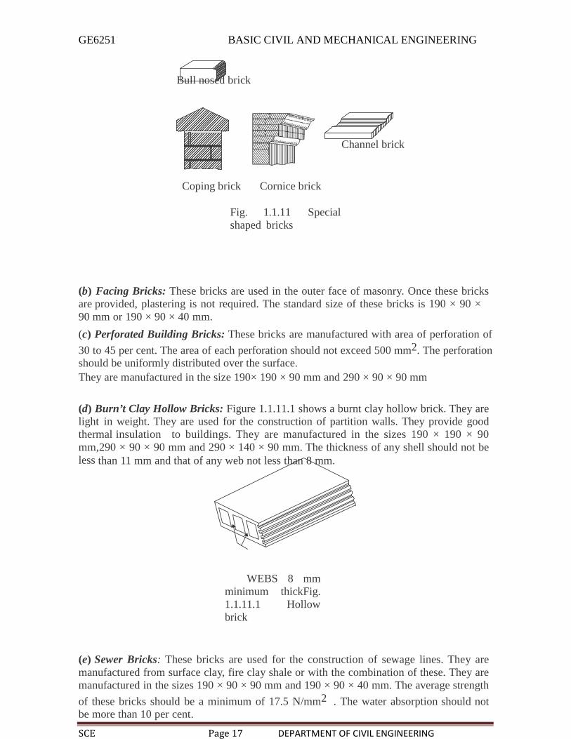
(a) Specially Shaped Bricks: Bricks of special shapes are manufactured to meet therequirements of different situations. Some of them are shown in Fig. 1.1.11.
GE6251 BASIC CIVIL AND MECHANICAL ENGINEERING
SCE Page 17 DEPARTMENT OF CIVIL ENGINEERING
Bull nosed brick
Channel brick
Coping brick Cornice brick
Fig. 1.1.11 Specialshaped bricks
(b) Facing Bricks: These bricks are used in the outer face of masonry. Once these bricksare provided, plastering is not required. The standard size of these bricks is 190 × 90 ×90 mm or 190 × 90 × 40 mm.
(c) Perforated Building Bricks: These bricks are manufactured with area of perforation of
30 to 45 per cent. The area of each perforation should not exceed 500 mm2. The perforationshould be uniformly distributed over the surface.They are manufactured in the size 190× 190 × 90 mm and 290 × 90 × 90 mm
(d) Burn’t Clay Hollow Bricks: Figure 1.1.11.1 shows a burnt clay hollow brick. They arelight in weight. They are used for the construction of partition walls. They provide goodthermal insulation to buildings. They are manufactured in the sizes 190 × 190 × 90mm,290 × 90 × 90 mm and 290 × 140 × 90 mm. The thickness of any shell should not beless than 11 mm and that of any web not less than 8 mm.
WEBS 8 mmminimum thickFig.1.1.11.1 Hollowbrick
(e) Sewer Bricks: These bricks are used for the construction of sewage lines. They aremanufactured from surface clay, fire clay shale or with the combination of these. They aremanufactured in the sizes 190 × 90 × 90 mm and 190 × 90 × 40 mm. The average strength
of these bricks should be a minimum of 17.5 N/mm2 . The water absorption should notbe more than 10 per cent.

GE6251 BASIC CIVIL AND MECHANICAL ENGINEERING
SCE Page 18 DEPARTMENT OF CIVIL ENGINEERING
( f ) Acid Resistant Bricks: These bricks are used for floorings likely to be subjected toacid attacks, lining of chambers in chemical plants, lining of sewers carrying industrialwastes etc. These bricks are made of clay or shale of suitable composition with low limeand iron content, flint or sand and vitrified at high temperature in a ceramic kiln.
1.1.11.1 Properties of Bricks
The following are the required properties of goodBricks:(i) Colour: Colour should beuniform and bright.
(ii) Shape: Bricks should have plane faces. They should have sharp and true right angledcorners.(iii) Size: Bricks should be of standard sizes as prescribed by codes.(iv) Texture: Theyshould possess fine, dense and uniform texture. They should not possess fissures,cavities, loose grit and unburnt lime.
(v) Soundness: When struck with hammer or with another brick, it should producemetallicsound.
(vi) Hardness: Finger scratching should not produce any impression on the brick.
(vii) Strength: Crushing strength of brick should not be less than 3.5 N/mm2. A fieldtest for strength is that when dropped from a height of 0.9 m to 1.0 mm on a hard ground,the brick should not break into pieces.
(viii) Water Absorption: After immercing the brick in water for 24 hours, water absorptionshould not be more than 20 per cent by weight. For class-I works this limit is 15 per cent.
(ix) Efflorescence: Bricks should not show white patches when soaked in water for 24hours and then allowed to dry in shade. White patches are due to the presence of sulphateof calcium, magnesium and potassium. They keep the masonry permanently in damp andwet conditions.(x) Thermal Conductivity: Bricks should have low thermal conductivity, so thatbuildings built with them are cool in summer and warm in winter.
(xi) Sound Insulation: Heavier bricks are poor insulators of sound while light weight andhollow bricks provide good sound insulation.
(xii) Fire Resistance: Fire resistance of bricks is usually good. In fact bricks are used toencase steel columns to protect them from fire
1.1.11.2 Tests on BricksThe following laboratory tests may be conducted on the bricks to find their
suitability:(i) Crushing strength
(ii) Absorption
(iii) Shape and size and
(iv) Efflorescence.
(i) Crushing Strength: The brick specimen are immersed in water for 24 hours. The frogof the brick is filled flush with 1:3 cement mortar and the specimen is stored in damp jutebag for 24 hours and then immersed in clean water for 24 hours. The specimen is placed in

GE6251 BASIC CIVIL AND MECHANICAL ENGINEERING
SCE Page 19 DEPARTMENT OF CIVIL ENGINEERING
compression testing machine with 6 mm plywood on top and bottom of it to get uniform
load on the specimen. Then load is applied axially at a uniform rate of 14 N/mm2 . Thecrushing load is noted. Then the crushing strength is the ratio of crushing load to the areaof brick loaded. Average of five specimen is taken as the crushing strength.
(ii) Absorption Test: Brick specimen are weighed dry. Then they are immersed in waterfor a period of 24 hours. The specimen are taken out and wiped with cloth.
The weight of each specimen in wet condition is determined. The difference in weightindicate the water absorbed. Then the percentage absorption is the ratio of water absorbedto dry weight multiplied by 100. The average of five specimen is taken. This value shouldnot exceed 20 per cent.iii) Shape and Size: Bricks should be of standard size and edges should be truelyrectangular with sharp edges. To check it, 20 bricks are selected at random and they arestacked along the length, along the width and then along the height. For the standardbricks of size 190 mm × 90 mm × 90 mm. IS code permits the following limits:
Lengthwise: 3680 to 3920mmWidthwise: 1740 to 1860mmHeightwise: 1740 to 1860mm
The following field tests help in acertaining the good qualitybricks:(i) uniformity in size(ii) uniformity in colour
(iii) structure
(iv) hardness test
(v) sound test
(vi) strength test.(i) Uniformity in Size: A good brick should have rectangular plane surface and uniform insize. This check is made in the field by observation.
(ii) Uniformity in Colour: A good brick will be having uniform colour throughout.This observation may be made before purchasing the brick.
(iii) Structure: A few bricks may be broken in the field and their cross-sectionobserved. The section should be homogeneous, compact and free from defects such asholes and lumps.(iv) Sound Test: If two bricks are struck with each other they should produce clear ringingsound. The sound should not be dull.
(v) Hardness Test: For this a simple field test is scratch the brick with nail. If noimpression is marked on the surface, the brick is sufficiently hard
(vi) Efflorescense: The presence of alkalies in brick is not desirable because they formpatches of gray powder by absorbing moisture. Hence to determine the presence of alkaliesthis test is performed as explained below:
Place the brick specimen in a glass dish containing water to a depth of 25 mm in awell ventilated room. After all the water is absorbed or evaporated again add water for adepth of 25 mm. After second evaporation observe the bricks for white/grey patches.The observation is reported as ‘nil’, ‘slight ‘moderate’, ‘heavy’ or serious to mean

GE6251 BASIC CIVIL AND MECHANICAL ENGINEERING
SCE Page 20 DEPARTMENT OF CIVIL ENGINEERING
(a) Nil: No patches
(b) Slight: 10% of area covered with deposits
(c) Moderate: 10 to 50% area covered with deposit but unaccompanied by flaking ofthe surface. (d) Heavy: More than 50 per cent area covered with deposits butunaccompanied by flaking the surface.
(e) Serious: Heavy deposits of salt accompanied by flaking of the surface.
1.1.11.3 Classification of Bricks Based on their Quality
The bricks used in construction areclassified as:
(i) First class bricks(ii) Second class bricks
(iii) Third class bricks and
(iv) Fourth class bricks(i) First Class Bricks: These bricks are of standard shape and size. They are burnt inkilns. They fulfill all desirable properties of bricks.
(ii) Second Class Bricks: These bricks are ground moulded and burnt in kilns. The edgesmay not be sharp and uniform. The surface may be some what rough. Such bricks arecommonly used for the construction of walls which are going to be plastered.
(iii) Third Class Bricks: These bricks are ground moulded and burnt in clamps. Theiredges are somewhat distorted. They produce dull sound when struck together. They areused for temporary and unimportant structures.
(iv) Fourth Class Bricks: These are the over burnt bricks. They are dark in colour. Theshape is irregular. They are used as aggregates for concrete in foundations, floors androads.
1.1.11.4 Uses of Bricks
Bricks are used in the following civilworks:
(i) As building blocks.(ii) For lining of ovens, furnaces and chimneys.(iii) For protecting steel columns from fire.(iv) As aggregates in providing water proofing to R.C.C. roofs.(v) For pavers for footpaths and cycle tracks.(vi) For lining sewer lines.
1.1.12CEMENT
Cement is a commonly used binding material in the construction. The cement is obtainedby burning a mixture of calcarious (calcium) and argillaceous (clay) material at a very hightemperature and then grinding the clinker so produced to a fine powder. It was firstproduced by a mason Joseph Aspdin in England in 1924. He patented it as portlandcement

GE6251 BASIC CIVIL AND MECHANICAL ENGINEERING
SCE Page 21 DEPARTMENT OF CIVIL ENGINEERING
1.1.12.1 Types of Cement
In addition to ordinary portland cement there are many varieties of cement. Importantvarieties are briefly explained below:
(i) White Cement: The cement when made free from colouring oxides of iron, maganeseand chlorium results into white cement. In the manufacture of this cement, the oil fuel isused instead of coal for burning. White cement is used for the floor finishes, plastering,ornamental works etc. In swimming pools white cement is used to replace glazed tiles. Itis used for fixing marbles and glazed tiles.
(ii) Coloured Cement: The cements of desired colours are produced by intimatelymixing pigments with ordinary cement. The chlorium oxide gives green colour. Cobaltproduce blue colour. Iron oxide with different proportion produce brown, red or yellowcolour. Addition of manganese dioxide gives black or brown coloured cement. Thesecements are used for giving finishing touches to floors, walls, window sills, roofs etc.(iii) Quick Setting Cement: Quick setting cement is produced by reducing thepercentage of gypsum and adding a small amount of aluminium sulphate during themanufacture of cement. Finer grinding also adds to quick setting property. This cementstarts setting within 5 minutes after adding water and becomes hard mass within 30minutes. This cement is used to lay concrete under static or slowly running water.(iv) Rapid Hardening Cement: This cement can be produced by increasing limecontent and burning at high temperature while manufacturing cement. Grinding to very fineis also necessary. Though the initial and final setting time of this cement is the same as thatof portland cement, it gains strength in early days. This property helps in earlier removalof form works and speed in construction activity.(v) Low Heat Cement: In mass concrete works like construction of dams, heat produceddue to hydration of cement will not get dispersed easily. This may give rise to cracks. Hencein such constructions it is preferable to use low heat cement. This cement contains lowpercentage (5%) of tricalcium aluminate (C3A) and higher percentage (46%) of dicalcium
silicate (C2S).
(vi) Pozzulana Cement: Pozzulana is a volcanic power found in Italy. It can be processedfrom shales and certain types of clay also. In this cement pozzulana material is 10 to 30per cent. It can resist action of sulphate. It releases less heat during setting. It impartshigher degree of water tightness. Its tensile strength is high but compressive strength islow. It is used for mass concrete works. It is also used in sewage line works.
(vii) Expanding Cement: This cement expands as it sets. This property is achieved byadding expanding medium like sulpho aluminate and a stabilizing agent to ordinarycement. This is used for filling the cracks in concrete structures.
(viii) High Alumina Cement: It is manufactured by calcining a mixture of lime andbauxite. It is more resistant to sulphate and acid attack. It develops almost full strengthwithin 24 hours of adding water. It is used for under water works.
(ix) Blast Furnace Cement: In the manufacture of pig iron, slag comes out as a wasteproduct. By grinding clinkers of cement with about 60 to 65 per cent of slag, this cementis produced. The properties of this cement are more or less same as ordinary cement, but itis cheap, since it utilise waste product.

GE6251 BASIC CIVIL AND MECHANICAL ENGINEERING
SCE Page 22 DEPARTMENT OF CIVIL ENGINEERING
This cement is durable but it gains the strength slowly and hence needs longer period ofcuring.
(x) Acid Resistant Cement: This cement is produced by adding acid resistant aggregatedsuch as quartz, quartzite, sodium silicate or soluble glass. This cement has goodresistance to action of acid and water. It is commonly used in the construction ofchemical factories.(xi) Sulphate Resistant Cement: By keeping the percentage of tricalcium aluminate C3A
below five per cent in ordinary cement this cement is produced. It is used in theconstruction of structures which are likely to be damaged by alkaline conditions.Examples of such structures are canals, culverts etc.
(xii) Fly Ash Blended Cement: Fly ash is a byproduct in thermal stations. The particles offly ash are very minute and they fly in the air, creating air pollution problems. Thermalpower stations have to spend lot of money to arrest fly ash and dispose safely.
It is found that one of the best way to dispose fly ash is to mix it with cement incontrolled condition and derive some of the beneficiary effects on cement. Now-a-dayscement factories produce the fly ash in their own thermal stations or borrow it from otherthermal stations and further process it to make it suitable to blend with cement. 20 to 30%fly ash is used for blending.
Fly ash blended cements have superior quality of resistance to weathering action. Theultimate strength gained is the same as that with ordinary portland cement. Howeverstrength gained in the initial stage is slow. Birla plus, Birla star, A.C.C. Suraksha aresome of the brand make of blended cement.
1.1.12.2 Properties of Ordinary Portland Cement
(i) Chemical properties: Portland cement consists of the following chemical compounds:
(a) Tricalcium silicate 3 CaO.SiO2 (C3S) 40%
(b) Dicalcium silicate 2CaO.SiO2 (C2S) 30%(c) Tricalcium aluminate 3CaO.Al2O3 (C3A) 11%(d) Tetracalcium aluminate 4CaO.Al2O3.Fe2O3
(C3AF)
11%There may be small quantities of impurifies present such as calcium oxide (CaO) and
magnesiumoxide (MgO).
When water is added to cement, C3A is the first to react and cause initial set. It
generates great amount of heat. C3S hydrates early and develops strength in the first 28
days. It also generates heat. C2S is the next to hydrate. It hydrates slowly and is
responsible for increase in ultimate strength. C4AF is comparatively inactive compound.
(ii) Physical properties: The following physical properties should be checkedbefore selecting a portland cement for the civil engineering works. IS 269–1967 specifiesthe method of testing and prescribes the limits:

GE6251 BASIC CIVIL AND MECHANICAL ENGINEERING
SCE Page 23 DEPARTMENT OF CIVIL ENGINEERING
(a) Fineness (b) Setting time
(c) Soundness (d) Crushing strength.
(a) Fineness: It is measured in terms of percentage of weight retained after sieving thecement through 90 micron sieve or by surface area of cement in square centimeters pergramme of cement. According to IS code specification weight retained on the sieveshould not be more than 10 per cent. In terms of specific surface should not be less than
2250 cm2/gm.b) Setting time: A period of 30 minutes as minimum setting time for initial setting and amaximum period of 600 minutes as maximum setting time is specified by IS code,provided the tests are conducted as per the procedure prescribed by IS 269-1967.
(c) Soundness: Once the concrete has hardened it is necessary to ensure that novolumetric changes takes place.
The cement is said to be unsound, if it exhibits volumetric instability after hardening. IScode recommends test with Le Chatelier mould for testing this property. At the end ofthe test, the indicator of Le Chatelier mould should not expand by more than 10 mm.
(d) Crushing strength: For this mortar cubes are made with standard sand andtested in compression testing machine as per the specification of IS code. The
minimum strength specified is 16 N/mm2 after 3 days and 22 N/mm2 after 7 days ofcuring.
1.1.12.3Uses o fCement
Cement is used widely for the construction of various structures. Some of themare listed below:
(i) Cement slurry is used for filling cracks in concrete structures.(ii) Cement mortar is used for masonry work, plastering and pointing.
iii) Cement concrete is used for the construction of various structures like buildings,bridges. water tanks, tunnels, docks, harhours etc.
(iv) Cement is used to manufacture lamp posts, telephone posts, railway sleepers, piles etc.
(v) For manufacturing cement pipes, garden seats, dust bins, flower pots etc. cement iscommonly used.
(vi) It is useful for the construction of roads, footpaths, courts for various sports etc.
1.1.13 Sand
Sand is a natural product which is obtained as river sand, nalla sand and pit sand.However sea sand should not be used for the following reasons:1. It contains salt and hence structure will remain damp. The mortar is affected byefflorenscence and blisters appear.
2. It contains shells and other organic matter, which decompose after some time, reducingthe life of the mortar.
Sand may be obtained artificially by crushing hard stones. Usually artificial sand isobtained as a by-product while crushing stones to get jelly (coarse aggregate).
GE6251 BASIC CIVIL AND MECHANICAL ENGINEERING
SCE Page 24 DEPARTMENT OF CIVIL ENGINEERING
Sand is used in mortar and concrete for the following purpose:
1. It sub-divides the paste of binding material into thin films and allows it to adhere andspread.
2. It fills up the gap between the building blocks and spreads the binding material.
3. It adds to the density of the mortar.
4. It prevents the shrinkage of the cementing material.
5. It allows carbon dioxide from the atmosphere to reach some depth and therebyimprove setting power.6. The cost of cementing material per unit volume is reduced as this low cost materialincreases the volume of mortar.
7. Silica of sand contributes to formation of silicates resulting into the hardenedmass.The properties of good sand are:1. It should be chemically inert.
2. It should be free from organic or vegetable matter.
3. It should be free from salt.
4. It should contain sharp, angular and coarse grains.
5. It should be well graded.
6. It should be hard.
1.1.13PLAIN CONCRETE
Plain concrete, commonly known as concrete, is an intimate mixture of binding material,fine aggregate, coarse aggregate and water. This can be easily moulded to desired shapeand size before it looses plasticity and hardens. Plain concrete is strong in compression butvery weak in tension. The tensile property is introduced in concrete by inducting differentmaterials and this attempt has given rise to RCC, RBC, PSC, FRC, cellular concrete andFerro cement. In this chapter proportioning, mixing, curing, properties, tests and uses ofplain concrete is dealt in detail. The other improved versions of concrete are explained andtheir special properties and uses are pointed out.Major ingredients of concrete are:
1. Binding material (like cement, lime, polymer)
2. Fine aggregate (sand)
3. Coarse aggregates (crushed stone, jelly)
4. Water.
A small quantity of admixtures like air entraining agents, water proofing agents,workability agents etc. may also be added to impart special properties to the plainconcrete mixture.Depending upon the proportion of ingredient, strength of concrete varies. It ispossible to determine the proportion of the ingredients for a particular strength by mixdesign procedure.

GE6251 BASIC CIVIL AND MECHANICAL ENGINEERING
SCE Page 25 DEPARTMENT OF CIVIL ENGINEERING
Com
pres
sive
stre
ngth
.In proportioning of concrete it is kept in mind that voids in coarse aggregates are filledwith sand and the voids in sand are filled with cement paste.FunctionsofVarious Ingredients
Cement is the binding material. After addition of water it hydrates and binds aggregatesand the surrounding surfaces like stone and bricks. Generally richer mix (with morecement) gives more strength. Setting time starts after 30 minutes and ends after 6 hours.Hence concrete should be laid in its mould before 30 minutes of mixing of water andshould not be subjected to any external forces till final setting takes place.
Coarse aggregate consists of crushed stones. It should be well graded and the stonesshould be of igneous origin. They should be clean, sharp, angular and hard. They givemass to the concrete and prevent shrinkage of cement. Fine aggregate consists of riversand. It prevents shrinkage of cement. When surrounded by cement it gains mobilityenters the voids in coarse aggregates and binding of ingradients takes place. It addsdensity to concrete, since it fills the voids. Denser the concrete higher is its strength.
Water used for making concrete should be clean. It activates the hydration ofcement and forms plastic mass. As it sets completely concrete becomes hard mass. Watergives workability to concrete which means water makes it possible to mix the concretewith ease and place it in final position. More the water better is the workability.
However excess water reduces the strength of concrete. Figure 1.1.13.1 shows thevariation of strength of concrete with water cement ratio. To achieve required workabilityand at the same time good strength a water cement ratio of 0.4 to 0.45 is used, in case ofmachine mixingand water cement ratio of 0.5 to 0.6 is used for handmixing.
Water/cement ratio1.1.13.1PropertiesofGreenconcrete
1. Workability: This is defined as the ease with which concrete can be compactedfully without seggregating and bleeding. It can also be defined as the amount of internalwork required to fully compact the concrete to optimum density. The workability dependsupon the quantity of water, grading, shape and the percentage of the aggregates present inthe concrete.
GE6251 BASIC CIVIL AND MECHANICAL ENGINEERING
SCE Page 26 DEPARTMENT OF CIVIL ENGINEERING
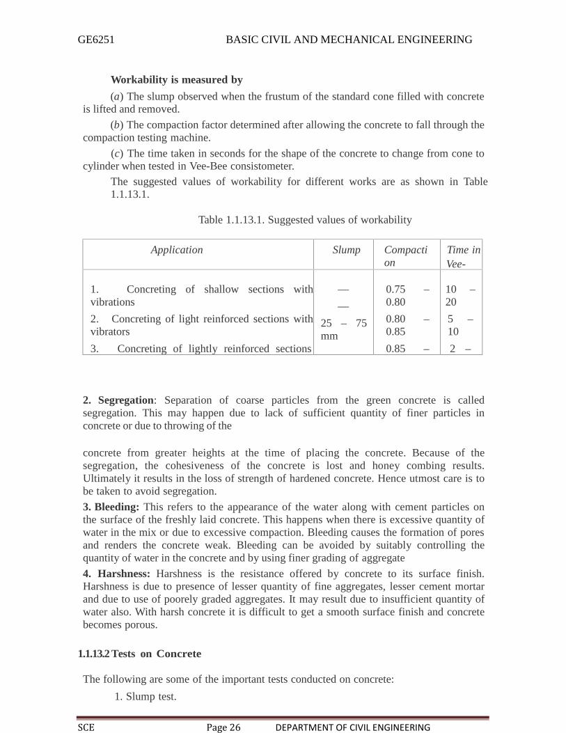
Workability is measured by
(a) The slump observed when the frustum of the standard cone filled with concreteis lifted and removed.
(b) The compaction factor determined after allowing the concrete to fall through thecompaction testing machine.
(c) The time taken in seconds for the shape of the concrete to change from cone tocylinder when tested in Vee-Bee consistometer.
The suggested values of workability for different works are as shown in Table1.1.13.1.
Table 1.1.13.1. Suggested values of workability
Application Slump Compaction
Factor
Time inVee-Bee
1. Concreting of shallow sections withvibrations
2. Concreting of light reinforced sections withvibrators
3. Concreting of lightly reinforced sectionswithout vibrations and heavily reinforcedsections with vibrations
4. Concreting of heavily reinforcedsections without vibration
——
25 – 75mm
75 – 125mm
0.75 –0.80
0.80 –0.85
0.85 –0.92
More than0.92
10 –20
5 –10
2 –5
—2. Segregation: Separation of coarse particles from the green concrete is calledsegregation. This may happen due to lack of sufficient quantity of finer particles inconcrete or due to throwing of the
concrete from greater heights at the time of placing the concrete. Because of thesegregation, the cohesiveness of the concrete is lost and honey combing results.Ultimately it results in the loss of strength of hardened concrete. Hence utmost care is tobe taken to avoid segregation.
3. Bleeding: This refers to the appearance of the water along with cement particles onthe surface of the freshly laid concrete. This happens when there is excessive quantity ofwater in the mix or due to excessive compaction. Bleeding causes the formation of poresand renders the concrete weak. Bleeding can be avoided by suitably controlling thequantity of water in the concrete and by using finer grading of aggregate
4. Harshness: Harshness is the resistance offered by concrete to its surface finish.Harshness is due to presence of lesser quantity of fine aggregates, lesser cement mortarand due to use of poorely graded aggregates. It may result due to insufficient quantity ofwater also. With harsh concrete it is difficult to get a smooth surface finish and concretebecomes porous.
1.1.13.2 Tests on Concrete
The following are some of the important tests conducted on concrete:
1. Slump test.

GE6251 BASIC CIVIL AND MECHANICAL ENGINEERING
SCE Page 27 DEPARTMENT OF CIVIL ENGINEERING
300
mm
2. Compaction factor test.
3. Crushing strength test.
1. Slump Test: This test is conducted to determine the workability of concrete. It needs aslump cone for test (Fig. 3.3). Slump cone is a vessel in the shape of a frustum of a conewith diameter at bottom 200 mm and 50 mm at top and 300 mm high. This cone is keptover a impervious platform and is filled with concrete in four layers.
Each layer is tamped with a 16 mm pointed rod for 25 times. After filling completely thecone is gently pulled up. The decrease in the height of the concrete is called slump. Higherthe slump, more workable is the concrete. The desired values of slumps forvariousworks have been shown in Table 1.1.13.1
50 mm
Slump
200 mmFig.1.1.13.1Slump test
2. Compaction Factor Test: This is another test to identify the workability of concrete.This test is conducted in the laboratory. The test equipment consists of two hoppers and acylinder fixed to a stand, the dimensions and the distances between the three vesselsbeing standardized. Vessel A and B are having hinged bottoms whereas cylinder C ishaving fixed bottom. [Ref. Fig. 1.1.13.2]
Top vessel A is filled with the concrete to be tested. As soon as it is filled, thehinged door is opened. Concrete is collected in vessel B. Then the hinged door of B isopened to collect concrete in cylinder C. The concrete in cylinder C is weighted. Let it beW1.
Now cylinder is again filled with the sample of concrete in 50 mm layers, which iscompacted by ramming and vibrating. Then the weight of compacted concrete isdetermined. Let this weight be W2.
The ratio W1/W2 is termed as compaction factor. The specified values of
compaction factor for different works are already listed in Table 3.2.

GE6251 BASIC CIVIL AND MECHANICAL ENGINEERING
SCE Page 28 DEPARTMENT OF CIVIL ENGINEERING
300
mm
300
mm
200
mm
230
mm
200
mm
280
mm
250mm
A
125mm
230mm
B
125mm
150mm
C
Fig. 1.1.13.2 Compaction factor test
3. Crushing Strength Test: Metallic moulds of size 150 mm × 150 mm × 150 mmare used for casting concrete cubes. Before filling mould, it is properly oiled on its innersurfaces, so that cubes can be easily separated. Fresh cube is filled with concrete to betested in 3 layers and kept in the room. After 24 hours, cube is removed from the mouldand kept under water for curing. After 28 days of curing cubes are tested in thecompression testing machine. In this test cubes are placed over the smooth surface whichis in contact with side plates of mould.

GE6251 BASIC CIVIL AND MECHANICAL ENGINEERING
SCE Page 29 DEPARTMENT OF CIVIL ENGINEERING
The crushing load is noted and crushing strength is found as load divided by
surface area (150 × 150 mm2). Code specify the desirable strength of concrete for 3 daysand 7 days for quick assessment of strength of concrete.
Desirable Properties Concrete
Appropriate quality and quantity of cement, fine aggregate, coarse aggregate and watershould be used so that the green concrete has the following properties:
(a) Desired workability
(b) No seggregation in transporting and placing
(c) No bleeding and
(d) No harshness
1.1.14FERROUS METALS
A ferrous material is the one in which iron is a main constituent. Iron ore is first convertedinto pig iron and then pig iron is subjected to various metallurgical processes to mixdifferent percentage of carbon and to get the following three useful ferrous materials:
1. Cast iron—carbon content 1.7% to 4.5%
2. Wrought iron—carbon content 0.05% to 0.15%
3. Steel—carbon content 0.25% to 0.25%.
All ferrous materials contain about 0.5 to 3% silica, less than 2% manganese, 0.15% sulphurand0.6% phosphorous.
1. Cast Iron: Important properties of cast iron are:
(a) Compression strength is 700 N/mm2 and tensile strength is 150
N/mm2.
(b) It is brittle and does not absorb shocks(c) Its specific gravity is 7.5.
(d) Its structure is coarse, crystalline and fibrous.(e) It cannot be magnetised.(f) It does not rust-easily.
(g) It has low melting point of about 1200°C.
Uses of Cast Iron:
1. It is used for making rain water and sanitary pipes, sanitary fittings and manhole covers.
2. It is used for making railings and spiral stair cases.
3. Fire gratings; cover for pumps and motors and brackets are made with cast irons.

GE6251 BASIC CIVIL AND MECHANICAL ENGINEERING
SCE Page 30 DEPARTMENT OF CIVIL ENGINEERING
Properties of Wrought Iron:
1. Its ultimate compressive strength is 200 N/mm2 and ultimate tensile strength is 375
N/mm2.
2. It is ductile and brittle.
3. Its unit weight is 77 kN/m3.
4. It melts at about 1500°C. It becomes so soft at 900°C that two pieces can bejoined by hammering.
5. It can absorb shocks very well.
6. It forms temporary magnets but it cannot be magnetised permanently.
7. It rusts more easily.
Uses of Wrought Iron:
1. It is used for making nails nuts and botts, wires and chains
2. It is used for making roofing sheets, grills, fences, window gaurds etc.
3. Steel: It is extensively used building material. The following three varieties of steelare extensively used:
(a) Mild steel
(b) High carbon steel and
(c) High tensile steel.
(a) Mild Steel: It contains a maximum of 0.25% carbon, 0.055% of sulphur and0.55% of phosphorus.
Properties of Mild Steel:
(i) It is malleable and ductile
(ii) It is more elastic
(iii) It can be magnetized permanently.(iv) Its specific gravity is 7.8.
(v) Its Young’s modulus is 2.1 × 10⁵ N/mm2.
(vi) It can be welded easily.
(vii) It is equally strong in tension and in compression.
Uses of Mild Steel:
(i) Round bars are extensively used as reinforcement in R.C.C. works.
(ii) Rolled sections like I, T, L, C, plates etc. are used to build steel columns, beams,trusses etc.
(iii) Tubular sections are used as poles and members of trusses.(iv) Plain and corrugated mild steel are used as roofing materials.(v) Mild steel sections are used in making parts of many types of machinery.
GE6251 BASIC CIVIL AND MECHANICAL ENGINEERING
SCE Page 31 DEPARTMENT OF CIVIL ENGINEERING
b) High Carbon Steel: The carbon contains in this steel is 0.7% to 1.5%.
Properties of Carbon Steel:
(i) It is more tough and elastic compared to mild steel.(ii) Welding is difficult.(iii) It can be magnetized permanently.
(iv) It is stronger in compression than in tension.(v) It withstands shocks and vibrations better.
Uses of High Carbon Steel:
(i) It is used for making tools such as drills, files, chisels.
(ii) Many machine parts are made with high carbon steel since it is capable ofwithstanding shocks and vibrations.
(c) High Tensile Steel: It contains 0.8% carbon and 0.6% manganese. The strength of thissteel is quite high. High tensile steel wires are used in prestressed concrete works.

GE6251 BASIC CIVIL AND MECHANICAL ENGINEERING
SCE Page 32 DEPARTMENT OF CIVIL ENGINEERING
UNIT IIBUILDING COMPONENTS AND STRUCTURES
Foundations: Types, Bearing capacity – Requirement of good foundations.Superstructure: Brick masonry – stone masonry – beams – columns – lintels – roofing –flooring –plastering – Mechanics – Internal and external forces – stress – strain – elasticity– Types of Bridges and Dams – Basics of Interior Design and Landscaping.
2.1 IntroductionEvery family needs a building to reside. Apart from residential purposes buildings arerequired for educational, institutional, business, assembly and for industrial purposes.Buildings are required for the storage of materials also.
In this chapter basic requirements of buildings are presented and then planning ofthe building with respect to orientation, utility of space, energy efficiency and otherrequirements are explained.
2.1.1 Elements of a building
The following are the basic elements of abuilding:
1. Foundation
2. Plinth
3. Walls and columns
4. Sills, lintels and chejjas
5. Doors and windows
6. Floors
7. Roofs
8. Steps, stairs and lifts
9. Finishing work
10. Building services.
The functions of these elements and the main requirement of them is presented in thisarticle.
1. Foundation: Foundation is the most important part of the building. Building activitystarts with digging the ground for foundation and then building it. It is the lower most partof the building. It transfers the load of the building to the ground. Its main functions andrequirements are:
(a) Distribute the load from the structure to soil evenly and safely.
(b) To anchor the building to the ground so that under lateral loads building will not move.(c) It gives level surface for the construction of super structure.
2. Plinth: The portion of the wall between the ground level and the ground floor level iscalled plinth. It is usually of stone masonry. If the foundation is on piles, a plinth beam iscast to support wall above floor level.
At the top of plinth a damp proof course is provided. It is usually 75 mm thick plainconcrete course.
GE6251 BASIC CIVIL AND MECHANICAL ENGINEERING
SCE Page 33 DEPARTMENT OF CIVIL ENGINEERING
The function of the plinth is to keep the ground floor above ground level, free ofdampness. Its height is not less than 450 mm. It is required that plinth level is at least 150mm above the road level, so that connections to underground drainage system can bemade.
3. Walls and Columns: The function of walls and columns is to transfer the load of thestructure vertically downwards to transfer it to foundation. Apart from this wall performsthe following functions also:
(a) It encloses building area into different compartments and provides
privacy.
(b) It provides safety from burglary and insects.
(c) It keeps the building warm in winter and cool in summer.
4. Sills, Lintels and Chejjas: A window frame should not be directly placed overmasonry. It is placed over 50 mm to 75 mm thick plain concrete course provided over themasonry. This course is called as sill. Lintels are the R.C.C. or stone beams provided overthe door and window openings to transfer the load transversely so as to see that door orwindow frame is not stressed unduly. The width of lintels is equal to the width of wallwhile thickness to be provided depends upon the opening size. Chejja is the projectiongiven outside the wall to protect doors and windows from the rain. They are usuallymade with R.C.C. In low cost houses stone slabs are provided as chejjas. The projectionof chejja varies from 600 mm to 800 mm. Sometimes drops are also provided to chejjas toimprove acsethetic look and also to get additional protection from sun and rain.
5. Doors and Windows: The function of a door is to give access to different rooms inthe building and to deny the access whenever necessary. Number of doors should beminimum possible. The size of the door should be of such dimension as will facilitate themovement of the largest object likely to use the door.
Windows are provided to get light and ventilation in the building. They are located at aheight of 0.75 m to 0.9 m from the floor level. In hot and humid regions, the window areashould be 15 to 20 per cent of the floor area. Another thumb rule used to determine the
size and the number of windows is for every 30 m3 of inside volume there should be 1
m2 window opening.
6. Floors: Floors are the important component of a building. They give working/usefularea for the occupants. The ground floor is prepared by filling brick bats, waste stones,gravel and well compacted with not less than 100 mm sand layer on its top. A lean concreteof 1 : 4 : 8, 100 mm thick is laid. On this a damp proof course may be provided. Then floorfinishing is done as per the requirement of the owner. Cheapest floor finish for a moderatehouse is with 20 to 25 mm rich mortar course finished with red oxide. The costliest floorfinish is mossaic or marble finishing.
7. Roof: Roof is the top most portion of the building which provide top cover to thebuilding. It should be leak proof. Sloping roof like tiled and A.C. sheet give leak proofcover easily. But they do not give provision for the construction of additional floor. Tiled
GE6251 BASIC CIVIL AND MECHANICAL ENGINEERING
SCE Page 34 DEPARTMENT OF CIVIL ENGINEERING
roof give good thermal protection.
Flat roofs give provision for additional floors. Terrace adds to the comfort ofoccupants. Water tanks can be easily placed over the flat roofs.8. Step, Stairs and Lifts: Steps give convenient access from ground level to ground floorlevel. They are required at doors in the outer wall. 250 to 300 mm wide and 150 mm riseis ideal size for steps. In no case the size of two consecutive steps be different. Number ofsteps required depends upon the difference in the levels of the ground and the floor. Stairsgive access from floor to floor. They should consists of steps of uniform sizes.
In all public buildings lifts are to be provided for the conveniences of old anddisabled persons. In hostels G + 3 floors can be built without lifts, but in residential flatsmaximum floors permitted without lifts is only G + 2. Lift is to be located near theentrance. Size of the lift is decided by the number of users in peak hours. Lifts areavailable with capacity 4 to 20 persons.
9. Finishing: Bottom portion of slab (ceiling), walls and top of floor need smoothfinishing with plaster. Then they are provided with white wash, distemper or paints ortiles. The function of finishing work is:
(a) Give protective cover
(b) Improve aesthetic view
(c) Rectify defective workmanship
(d) Finishing work for plinth consists in pointing while for floor it consists inpolishing.
10. Building Services: Water supply, sanitation and drainage works, electric supply workand construction of cupboards and show cases constitute major building services.
For storing water from municipal supply or from tanker a sump is built in the houseproperty near street. From the sump water is pumped to over head tanks placed on orabove roof level so as to get water all the 24 hours. Plumbing work is made so as to getwater in kitchen, bathrooms, water closets, sinks and garden taps.
For draining rain water from roofs, down take pipes of at least 100 mm diametersshould be used. Proper slopes should be given to roof towards down take pipe. Thesepipes should be fixed at 10 to 15 mm below the roof surface so that rain water is directedto the down take pipe easily.
The sanitary fittings are to be connected to stone ware pipes with suitable tr
aps and chambers. Stone ware pipes are then connected to underground drainage ofmunicipal lines or to the septic tank.
Many carpentry works are required for building service. They are in the form ofshowcases, cupboards, racks etc.
Electric supply is essential part of building services. The building should beprovided with sufficient points for supply of lights, fans and other electric gadgets.

GE6251 BASIC CIVIL AND MECHANICAL ENGINEERING
SCE Page 35 DEPARTMENT OF CIVIL ENGINEERING
2.1.1.2 Basic requirements of a building
The planning and construction of a building should be aimed at fulfilling the followingrequirements:
1. Strength and stability
2. Dimensional stability
3. Resistance to dampness
4. Resistance to fire
5. Heat insulation
6. Sound insulation
7. Protection against termite attack
8. Durability
9. Security against burglary
10. Lighting and ventilation
11. Comforts and convenience
12. Economy.
1. Strength and Stability: Building should be capable of transferring the expected loads inits life period safely to the ground. Design of various structural components like slabs,beams, walls, columns and footing should ensure safety. None of the structuralcomponents should buckle, overturn and collapse.
2. Dimensional Stability: Excessive deformation of structural components give a senseof instability and result into crack in walls, flooring etc. All structural components, shouldbe so designed that deflections do not exceed the permissible values specified in thecodes.
3. Resistance to Dampness: Dampness in a building is a great nuisance and it may reducethe life of the building. Great care should be taken in planning and in the construction ofthe building to avoid dampness.
4. Resistance to Fire: Regarding achieving resistance to fire, the basic requirements laiddown in the codes are:
(a) the structure should not ignite easily.
(b) building orientation should be such that spread of fire is slow.
(c) In case of fire, there should be means of easy access to vacate building quickly.
5. Heat Insulation: A building should be so oriented and designed that it insulatesinterior from heat.
6. Sound Insulation: Buildings should be planned against outdoor and indoor noises.
7. Protection from Termite: Buildings should be protected from termites.
8. Durability: Each and every component of the building should be durable.

GE6251 BASIC CIVIL AND MECHANICAL ENGINEERING
SCE Page 36 DEPARTMENT OF CIVIL ENGINEERING
9. Security against Burglary: This is the basic need the owner of the building expects
10. Lighting and Ventilation: For healthy and happy living natural light andventilations are required. Diffused light and good cross ventilation should be availableinside the building.
11. Comforts and Conveniences: Various units in the building should be properlygrouped and integrated keeping in mind the comfort and convenience of the user.
12. Economy: Economy without sacrificing comfort, convenience and durability is anotherbasic requirement of the building.
2 .1.1..3 PLANNING
All buildings should be properly planned, keeping in view the various requirements of agood building. Except strength requirement, all other requirements of a good buildings aretaken care at the stage of planning. Strength requirement is taken care during structuraldesign of building components. However in planning the building by-laws of the statutoryauthorities should not be violated. Planning of the building is an art combined withscience.
Principles of planning of buildings may be grouped into:
1. Orientation
2. Energy efficiency
3. Utility
4. Other requirements of the building.
2.1.1.4 Planning suitable orientation
Orientation means setting out the plan of the building with respect to north-south and east-west directions to provide an opportunity to user to enjoy sun-shine and breeze whenrequired and to avoid the same whenever not required. This is also known as planning theaspect of a building. Aspect means arrangement of doors, windows in the external wall tomake good use of nature. This term has nothing to do with the architectural aspect ofoutlook of building. Kitchen should have eastern aspect to enjoy morning sunshine, means,kitchen should be located on the eastern side of the building to make use of morning sunrays. The following are the required aspects for various parts of the building in the northernhemisphere of earth:
(a) Kitchen–eastern aspect.
(b) Dining room–southern aspect to enjoy winter sun.
(c) Drawing and living room–southern or south-eastern aspect to enjoy
winter sun. (d) Bed rooms–western or south-western aspect to enjoy
breez in summer.
(e) Reading room, class room, stairs, northern aspect to enjoy diffused light.
GE6251 BASIC CIVIL AND MECHANICAL ENGINEERING
SCE Page 39 DEPARTMENT OF CIVIL ENGINEERING
2.1.1.5 Planning for energy efficiency
A building should be planned in such a manner that it gives maximum day lighting,ventilation and heat insulation. If these requirements are fulfilled, requirement of electricenergy comes down.
(a) Light: Natural light provides hygenic atmosphere. Light should not be glaringbut it should be uniformly distributed. Providing windows and ventilators of appropriatesize at suitable positions contributes a lot for natural lighting. For residential buildingswindow area to floor area should not be less than 1/10th while for school buildings itshould not be less than 1/5th of floor area. For factory buildings north light trusses shouldbe provided to get maximum diffused light.
(b) Ventilation: Ventilation is the circulation of the air in the building. Naturalventilation can be achieved by selecting and positioning of doors, windows andventilators at suitable places. Always cross ventilations should be planned suitably.Provision of ventilators at roof level helps in driving out hot airs. In case it is not possibleto achieve natural ventilation for any part of the building provide ordinary or exhaustfans.
(c) Heat Insulation: Thicker exterior walls provide insulation against heat. Properventilation also helps in achieving heat insulation. Sun shades provided to doors,windows and ventilators help in achieving heat insulation. In factories and assembly hallsheight should be more to reduce temperature inside the building. The position of furnacesin the factories should be located away from the other partsof the factory. The openings should be provided at higher level in the wall to remove hotair.
2.1.1.6 Planning for suitable utility
Principles of planning for suitableutility are:
1. Roominess
2. Furniture Requirements
3. Groupings
4.Circulation.

GE6251 BASIC CIVIL AND MECHANICAL ENGINEERING
SCE Page 40 DEPARTMENT OF CIVIL ENGINEERING
2.1.1.7 Planning for meeting other requirements
Principle of planning involves planning for meeting the followingrequirements also:
1. Sanitary convenience
2. Prospects
3. Elegance
4. Flexibility
5. Privacy
6. Resistance to fire
7. Sound insulation
8. Protection from termite
9. Security against burglary
10.Econoy
11. Provisions for future alterations.
2.2 C o n v e n t i o n a l spread footings
This type of foundations is commonly used for walls and masonry columns. Thesefoundations are built after opening the trenches to required depth. Such footings areeconomical up to a maximum depth of 3 m. As these foundations are suitable depth, theyare grouped under shallow foundations.
Figure 2.2.1 shows a conventional spread footing for a wall and Fig. 2.2.2 showsit for a masonry column.
300
300 450
300
600
300
750
150
1050
Fig. 2.2.1. Wall footing Fig. 2.2.2 Foundation for masonry pier

GE6251 BASIC CIVIL AND MECHANICAL ENGINEERING
SCE Page 41 DEPARTMENT OF CIVIL ENGINEERING
Before building these footing trenches are opened to required depth and the soil is rammedwell. Then a plain concrete of mix 1 : 4 : 8 is provided. Its thickness varies from 150 to200 mm. Over this bed, stone masonry footing is built. It is built in courses each courseprojecting 50 to 75 mm from the top course and height of each course being 150 to 200mm. In case of wall footing the projections are only one direction while in case ofcolumns, they are in both directions. The projection of bed concrete from the lowest courseof foundation masonry is usually 150 mm.
2.2.2 R.C.C. footings
There are mainly two types of R.C.C.footings:
1. One way reinforcedfootings.
2. Two way reinforcedfootings.
1. One Way Reinforced Footing: These footings are for the walls. In thesefootings main reinforcements are in the transverse direction of wall. In longitudinaldirections there will be only nominal reinforcement.
2. Two Way Reinforced Footings: For columns two way reinforced footings areprovided. The following types of the footings are common:
(i) Isolated Column Footings: If separate footings are provided for each column,it is called isolated column footing. Figure 2.2.2.1 shows a typical isolated columnfooting. The size of footing is based on the area required to distribute the load of thecolumns safely over the soil .These footings are provided over a 100 to 150 mm bedconcrete. Required reinforcements and thickness of footing arefound by the design engineers. Thickness may be uniform or varying.
R.C.C.column
R.C.C.footing
Plan concrete bed
(a) Footing with uniform thickness (b) Sloping footing
Fig. 2.2.2.1 Isolated R.C.C. footing

GE6251 BASIC CIVIL AND MECHANICAL ENGINEERING
SCE Page 42 DEPARTMENT OF CIVIL ENGINEERING
Strap beam
(ii) Combined Footings: Common footings may be provided for two columns.This type of footing is necessary when a column is very close to the boundary of theproperty and hence there is no scope to project footing much beyond the column face.Figure 2.2.2.2 shows a typical combined footing. The footing is to be designed fortransferring loads from both columns safely to the soil. The two columns may or maynot be connected by a strap beam.
Strap beam
Footing
Fig. 2.2.2.2. Combined footing [Strap beam may or may not beprovided]
(iii) Continuous Footings: If a footing is common to more than two columns in arow, it is called continuous footing. This type of footing is necessary, if the columns in arow are closer or if SBC of soilis low. Figure 2.2.2.3shows this type of footing.
Fig.2.2.2.3 Continuous footing
(iv) Mat Footing/Raft Footing: If the load on the column is quite high (Multistoreycolumns) or when the SBC of soil is low, the sizes of isolated columns may work out to beto such an extent that they overlap each other. In such situation a common footing may beprovided to several columns as shown in Fig. 2.2.2.4 Such footings are known as raftfootings.
If the beams are provided in both directions over the footing slab for connectingcolumns, the raft foundations may be called as grid foundation also.

GE6251 BASIC CIVIL AND MECHANICAL ENGINEERING
SCE Page 43 DEPARTMENT OF CIVIL ENGINEERING
The added advantage of such footing is, settlement is uniform and hence unnecessarystresses are not produced.
Fig.2.2.2.4 Raft foundation

GE6251 BASIC CIVIL AND MECHANICAL ENGINEERING
SCE Page 44 DEPARTMENT OF CIVIL ENGINEERING
Firs
ttie
r
100
mm
(min
)
2.2.2.1 Grillage footing
High rise buildings are built with steel columns encased in concrete. Such columns carryvery heavy load and hence they need special foundations to spread the load to a larger areaof soil. Grillage foundation is one such special foundation. It consists of one tier or moretiers of I-sections steel beams. Fig 2.2.2.5 shows a typical two tier grillage foundation.Top tier consists of less number but large size steel section while lower tier consists oflarger number but smaller size steel sections. Column load is transferred to the top tierthrough a base plate. The grillage beams are unpainted and are encased in concrete withminimum cover of 100 mm beyond the edges of steel sections. A minimum clear space of75 mm should be maintained between the flanges of adjacent grillage beams so thatconcreting can be made properly.To maintain spacing, pipe separators are used.
Steel Fig. 2.2.2.5Grillage foundation
columnGusset plate
Pipeseparators
Angle cleat
Base plate
First tier
Secondtier
150 mm(a)Section of AB.
PipeA Separators B
Plan

GE6251 BASIC CIVIL AND MECHANICAL ENGINEERING
SCE Page 45 DEPARTMENT OF CIVIL ENGINEERING
2.2.3 Arch foundation
Inverted arch foundations are provided in the places where the SBC of the soil is very poorand the load of the structure is through walls. In such cases inverted arches areconstructed between the walls. End walls should be sufficiently thick and strong towithstand the outward horizontal thrust due to arch action. The outer walls may beprovided with buttress walls to strengthen them. Figure 2.2.3.1 shows a typical invertedarch footing.
Wall
Inverted archFig. 2.2.3.1 Invertedarch footing
2.2.4 Pile foundations
These foundations are known as deep foundations. A pile is a slender column made ofwood, concrete or steel. A pile is either driven into the soil or formed in situ by excavatinga hole and then filling it with concrete. A group of piles are driven to the required depthand are capped with R.C.C. slab, over which super structure is built. The pile transfer theload to soil by friction or by direct bearing, in the latter case, piles being taken up to hardstrata. This type of foundations is used when top soil is not capable of taking the load ofthe structure even at 3–4 m depth.
Column Column
Pile cap Pile cap
GL GL
Piles Piles
Hard strata
(a) Bearing pile (b) Friction pile
Fig. 2.2.4.1 Pilefoundations

GE6251 BASIC CIVIL AND MECHANICAL ENGINEERING
SCE Page 46 DEPARTMENT OF CIVIL ENGINEERING
Pile foundations are classified according to the materials used and also on the nature ofload transfer.
Classification According to Materials Used:
Piles may be classified as:
(a) Timber piles(b) Concrete piles
(c) Steel piles and
(d) Composite piles.(a) Timber piles: Circular seasoned wood can be used as piles. Their diameter may varyfrom 200 mm to 400 mm. Similarly square piles of sizes 200 mm to 400 mm are also used.The length of timber pile should not be more than 20 times its lateral dimension. Thebottom of the pile is sharpened and is provided with iron shoe, so that it can be driven in theground easily by hammering. These piles should be always kept below water table;otherwise alternating wet and dry condition cause the decay. These piles are cheap and canbe easily driven rapidly. The main disadvantage is their load carrying capacity is low andare likely to be damaged during driving in the soil.(b) Concrete piles: These piles may be further classified as precast piles and cast in situpiles. Precast piles are reinforced with steel and are manufactured in factories. Thecross-section diameter/dimension varies from 200 mm to 500 mm. Square, circularand octagonal sections are commonly used. The length of piles may be up to 20 m. Theyare provided with steel shoe at the lowest end. These piles can carry fairly large loads.These piles are highly resistant to biological and chemical actions of the soil. Thedisadvantage of these piles is they need more time to manufacture and are heavy to handle.
Figure 2.2.4.2(a) and (b) show concrete piles.
Beam
Pile
Under ream
Under ream
(a) Pressure pile
(b) Under-reamed pile
Fig. 2.2.4.2. Cast in situ concrete pile

GE6251 BASIC CIVIL AND MECHANICAL ENGINEERING
SCE Page 47 DEPARTMENT OF CIVIL ENGINEERING
Cast in situ concrete piles are formed first by boring the holes in the soil and thenconcreting them. Concreting is usually made using casing tubes. If the hole is filled withonly plain concrete it is pressure pile. The load carrying capacity of the piles may beincreased by providing enlarged base.
The reinforcement caging may be inserted in the bored holes and to increase loadcarrying capacity one or two under reams may be formed. After that concreting may becarried out. Such piles are known as under reamed piles. These piles are provided atregular interval of 2 to 4 m and capping beam is provided over them.
(c) Steel Piles: A steel pile may be a rolled steel I sections, tubes or fabricated in the formof box. These piles are mostly used as bearing piles since surface available for friction isless and also the coefficient of friction is less. If tubes are used the soil inside the tube isdriven out by compressed air and concrete is filled. These piles are very useful fordriving close to existing structures since they disturb the soil least.
(d) Composite Piles: Composite piles may be of concrete and timber or of concrete andsteel. Wooden piles should not be subjected to alternating wet and dry conditions. Hencethey are preferred for the portion below water table. The portion above water table arebuilt with cast in situ concrete piles.
If the required length of steel piles is less than the depth of pile, many times upperportions are built with concrete. Thus steel and concrete composite piles are sometimesused.
Classification of Piles According to Load Transfer:
According to the load transfer to the soil piles may be classified as
(a) Bearing piles and
(b) Friction piles.
Bearing piles rest on hard strata and transfer the load by bearing. Such piles are preferred.These piles are used if the hard strata are available at reasonable depth.
Friction piles transfer the load to the soil by the friction between soil and the pile. Suchpiles are used if hard strata are not available to a considerable depth. The frictiondeveloped is to be properly assessed before deciding the length of the pile. The surface ofsuch piles is made rough to increase the skin friction so that required length of pile isreduced.
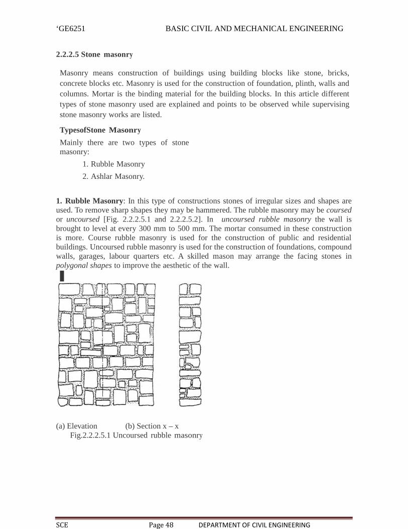
‘GE6251 BASIC CIVIL AND MECHANICAL ENGINEERING
SCE Page 48 DEPARTMENT OF CIVIL ENGINEERING
2.2.2.5 Stone masonry
Masonry means construction of buildings using building blocks like stone, bricks,concrete blocks etc. Masonry is used for the construction of foundation, plinth, walls andcolumns. Mortar is the binding material for the building blocks. In this article differenttypes of stone masonry used are explained and points to be observed while supervisingstone masonry works are listed.
TypesofStone Masonry
Mainly there are two types of stonemasonry:
1. Rubble Masonry
2. Ashlar Masonry.
1. Rubble Masonry: In this type of constructions stones of irregular sizes and shapes areused. To remove sharp shapes they may be hammered. The rubble masonry may be coursedor uncoursed [Fig. 2.2.2.5.1 and 2.2.2.5.2]. In uncoursed rubble masonry the wall isbrought to level at every 300 mm to 500 mm. The mortar consumed in these constructionis more. Course rubble masonry is used for the construction of public and residentialbuildings. Uncoursed rubble masonry is used for the construction of foundations, compoundwalls, garages, labour quarters etc. A skilled mason may arrange the facing stones inpolygonal shapes to improve the aesthetic of the wall.
(a) Elevation (b) Section x – xFig.2.2.2.5.1 Uncoursed rubble masonry

‘GE6251 BASIC CIVIL AND MECHANICAL ENGINEERING
SCE Page 49 DEPARTMENT OF CIVIL ENGINEERING
Fig. 2.2.2.5.2 Coursed rubble masonry
2. Ashlar Masonry: In this type of masonry stones are dressed to get suitable shapes andsizes. The height of the stones varies from 250 mm to 300 mm. The length should notexceed three times the height. The dressing of the stone need not be very accurate on allsides. Usually good dressing is made on facing side. In such construction mortarconsumption is less compared to rubble masonry.There are different types of ashlar masonry depending upon the type of dressing such asAshlar fine dressed, Ashlar rough dressed, Ashlar rock or quarry faced, Ashlar facing,Ashlar chamfered etc. Figure 8.3 show some of such masonry

‘GE6251 BASIC CIVIL AND MECHANICAL ENGINEERING
SCE Page 50 DEPARTMENT OF CIVIL ENGINEERING
(b) Ashlar chamfered
(a)Fig.2.2.2.5.3 Fine finished ashlar Fig.2.2.2.5.4Ashlar masonry
Supervision of Stone Masonry Construction
The following points should be kept in mind in supervising stone masonry work:
1. Hard and durable stones, free from defects like flaws, cavities veins etc. shouldbe used.
2. Dressing of the stones should be as per the requirement.
3. Stones should be properly wetted before they are used so as to avoid sucking ofwater from mortar.
4. Stones should be laid on their natural bed.
5. Facing and backing faces should be laid neatly and levelled and checked withwooden template.
6. The heart of masonry should be filled with stone chips and mortars. To thickmortar joints should be avoided.
7. Verticality of the wall should be frequently checked with plumb-bob.
8. Mortars with correct proportion of sand and cement should be used.
9. Continuous vertical joints should be avoided.
10. Through stones should be used within 1.5 m distances.
11. The height of masonry should be raised uniformly.
12. Under the beams, trusses, sills etc large flat stones should be used.
13. Before continuing work, the masonry built on previous day should be wellcleaned and freed from loose particles.
14.Curing should be done properly for 2 to 3 weeks.

‘GE6251 BASIC CIVIL AND MECHANICAL ENGINEERING
SCE Page 51 DEPARTMENT OF CIVIL ENGINEERING
2.6 Brick masonry
Brick masonry is built with bricks bonded together with mortar. For temporary shedsmud mortar may be used but for all permanent buildings lime or cement mortars areused.
The various types of bonds generally used in brick masonry are
1. Stretcher bond
2. Header bond
3. English bond and
4. Flemish bond.
1. Stretcher Bond: A stretcher is the longer face of the brick as seen in the elevation. Inthe brick of size 190 mm × 90 mm × 90 mm, 190 mm × 90 mm face is the stretcher. Instretcher bond masonry all the bricks are arranged in stretcher courses as shown in Fig.2.6.1 However care should be taken to break vertical joints. This type of construction isuseful for the construction half brick thick partition wall.
4
3
2
1A (a) Elevation B
1, 3, 5 ... Courses(b) Plan
Fig. 2.6.1 Stretcherbond
2. Header Bond: A header is the shorter face of the brick as seen in the elevation. In astandard brick it is 90 mm × 90 mm face. In header bond brick masonry all the bricks arearranged in the header courses as shown in Fig. 2.6.2. This type of bond is useful for theconstruction of one brick thick wall
4
3
2
1
34Bats
1, 3, 6 ... Courses
(a) Elevation (b) Plan
Fig. 2.6.2 Headerbond
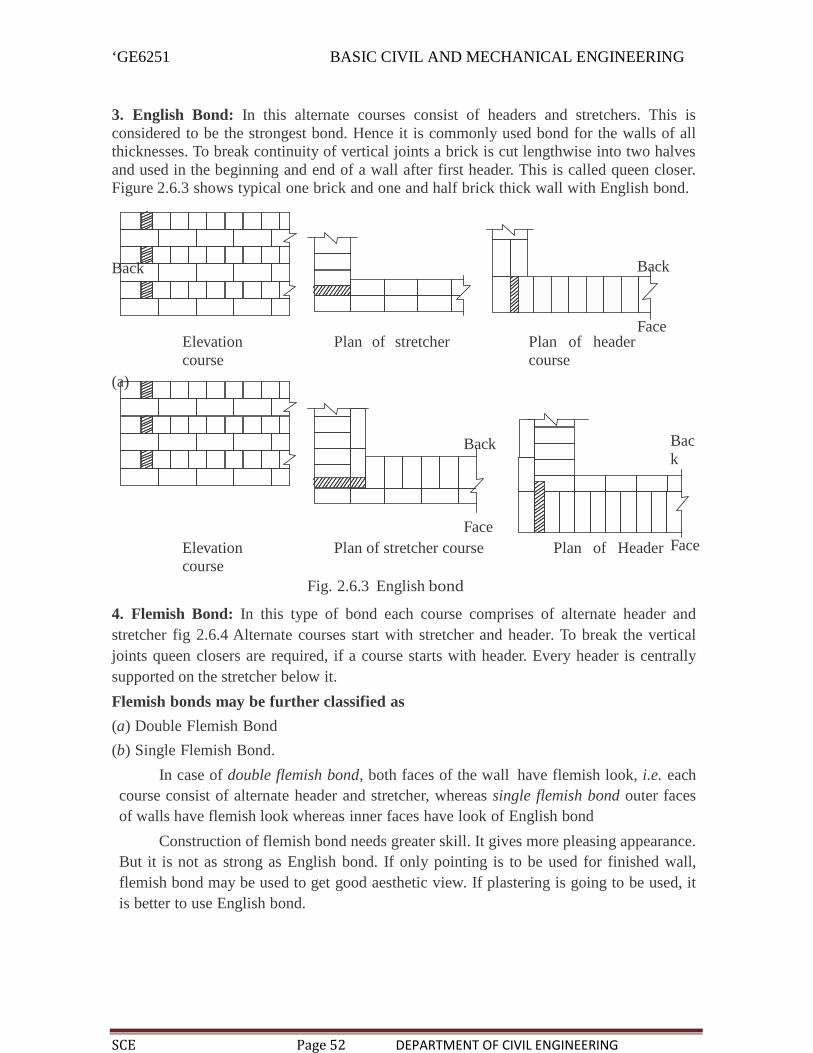
‘GE6251 BASIC CIVIL AND MECHANICAL ENGINEERING
SCE Page 52 DEPARTMENT OF CIVIL ENGINEERING
3. English Bond: In this alternate courses consist of headers and stretchers. This isconsidered to be the strongest bond. Hence it is commonly used bond for the walls of allthicknesses. To break continuity of vertical joints a brick is cut lengthwise into two halvesand used in the beginning and end of a wall after first header. This is called queen closer.Figure 2.6.3 shows typical one brick and one and half brick thick wall with English bond.
Back Back
Elevation Plan of stretchercourse
(a)
Plan of headercourse
Face
Back
FaceElevation Plan of stretcher course Plan of Headercourse
Back
Face
Fig. 2.6.3 English bond
4. Flemish Bond: In this type of bond each course comprises of alternate header andstretcher fig 2.6.4 Alternate courses start with stretcher and header. To break the verticaljoints queen closers are required, if a course starts with header. Every header is centrallysupported on the stretcher below it.
Flemish bonds may be further classified as
(a) Double Flemish Bond
(b) Single Flemish Bond.
In case of double flemish bond, both faces of the wall have flemish look, i.e. eachcourse consist of alternate header and stretcher, whereas single flemish bond outer facesof walls have flemish look whereas inner faces have look of English bond
Construction of flemish bond needs greater skill. It gives more pleasing appearance.But it is not as strong as English bond. If only pointing is to be used for finished wall,flemish bond may be used to get good aesthetic view. If plastering is going to be used, itis better to use English bond.

‘GE6251 BASIC CIVIL AND MECHANICAL ENGINEERING
SCE Page 53 DEPARTMENT OF CIVIL ENGINEERING
The following points should be observed in the construction ofbrick masonry:
1. Use bricks of good quality with uniform colour, well burnt, with exact shape and size.
2. Before using the bricks in masonry, they should be soaked in water for 2 hours so thatbricks do not absorb water from the mortar.3. Bricks should be laid with the frog pointing upward.
4. Construction of brick wall should start from the end or corner.
5. Brick courses should be perfectly horizontal.
6. Verticality of the wall should be ensured by frequently checking with plumb-bob.
7. Mortar used should be as per specification.
8. Whenever work is stopped brick masonry should be left with toothed end.
9. Use of brick bats should be avoided.
10. Walls should be raised uniformly. In no case difference between adjoining walls bemore than 1 m. In a day no wall should be raised by more than 1.5 m.
11. To get proper key for plastering or pointing, the face joints should be raised to a depthof 12 to 20 mm, when the mortar is green. If plastering or pointing is not to be provided,face joints should be stuck flush and finished neatly.
12. Holdfasts for doors and windows should be embedded in brick masonry with cementmortar or concrete, at the time of constructing the wall itself.
13. Brick masonry should be regularly cured for 2 weeks.
14. For carrying out brick work at higher levels, only single scaffolding should be used.
Advantages and Disadvantages of Brick Masonry Over Stone Masonry
Advantages:
1. Since shape and size of bricks are uniform, it do not need skilled labour for theconstruction.
2. Bricks are light in weight and hence handling them is easy.
3. Bricks are easily available around cities and their transportation cost is lessbecause their weight is less. Stones are to be brought from quarries which arelocated only at few places.
4. It is possible to use all types of mortar in brick masonry. For unimportantbuildings even mud mortar can be used.
5. Thinner walls can be constructed with bricks but it is not so with stones.
6. It is easy to form openings for doors and windows.
7. Dead load of brick masonry is less.
8. In brick masonry mortar joints are thin and hence construction cost is reducedconsiderably.
9. Brick masonry has better fire and weather resistance compared to stonemasonry.

‘GE6251 BASIC CIVIL AND MECHANICAL ENGINEERING
SCE Page 54 DEPARTMENT OF CIVIL ENGINEERING
Disadvantages:
1. Strength of brick masonry is less than that of stone masonry.
2. Durability of brick masonry is less.
3. Brick masonry needs plastering and plastered surface needs colour washing.Stone masonry don’t need them and hence maintenance cost is more in brickmasonry.
4. Brick masonry absorbs water and there are possibility of dampness. There is nosuch problem in stone masonry.
5. More architectural effects can be given in stone masonry compared to that inbrick masonry.
6. Stone masonry gives massive appearance and hence monumental buildings arebuilt in stone masonry.
2.7 BeamsBeams are defined as horizontal load carrying member in a structure. Reinforced cementconcrete, concrete, prestressed concrete and steel I sections are used as beams to support theslabs.Classified: Simply supported beam Rigidly fixed beam Cantilever beam Over hanging beam Continuous beam
Simply supported beam:If the ends of a beam are supported freely by columns it is called simply supported beam
Rigidly fixed beam:It the two ends of a beam is rigidly fixed in walls then it is called fixed beams. In suchcases, the moment is induced at supports because it will not allow rotation.
Cantilever beam:If a beam is fixed in one end and the other end is free then it is called cantilever beam.
Overhanging beam:If a beam having its end portion extended beyond the support, it is called overhangingbeam.
Continuous beam:If a beam is supported on more than two supports, then it is known as continuous beam.

‘GE6251 BASIC CIVIL AND MECHANICAL ENGINEERING
SCE Page 55 DEPARTMENT OF CIVIL ENGINEERING
2.8 ColumnsThe vertical load carrying member of a structure is called column. They are constructed oftimber, stone, reinforced cement concrete of steel section.
Classified: Long column Short column
Long columnThe ratio of effective length to least later dimension is less than 12 called as long column
Short columnThe ratio of effective length to least later dimension is more than 12 called as long column

‘GE6251 BASIC CIVIL AND MECHANICAL ENGINEERING
SCE Page 56 DEPARTMENT OF CIVIL ENGINEERING
Reinforced cement concrete columnUsually the reinforced cement concrete column are cast in-situ type. They may beconstructed in square, rectangular, circular shapes. Vertical reinforcements or mainreinforcements are provided to take up major load coming over the column. Generally thediameter of vertical reinforcement may vary from 10mm to 40mm.Longitudinalreinforcement bars should not be less than 0.8% and not more than 6% of the crosssectional area of the column. The diameter of lateral reinforcement may vary from 6mm to10mm.
In the multi storyed buildings, the section of the column in upper stories may be reduced asthey have to carry lesser loads. But the centre lines of various columns of different storiesmust coincide in a same vertical line.
Steel columns
The various cross sections of steel columns are shown in fig. Struts of one or two angles areused as compression member in roof trusses. Latticed columns made up of channels orangles connected by lattice bars are often used where light loads are to be supported on longcolumns. battened columns made up of channels or angles connected only batten plate arealso used as column. Rolled H-columns which are available in depths ranging from 150 mmto 500 mm and are now commonly used in steel Skelton construction

‘GE6251 BASIC CIVIL AND MECHANICAL ENGINEERING
SCE Page 57 DEPARTMENT OF CIVIL ENGINEERING
.
2.9 LintelsA lintel is a horizontal member which is placed across the openings. Openings areinvariably left in the wall for the provision of doors, windows etc. A lintel is thus a sort ofbeam, the width of which is equal to the width of which is equal to the width of the wall,and the ends of which are built into the wall.
Classification Timber lintels Stone lintels Brick lintels Steel lintels Reinforced cement concrete lintels

‘GE6251 BASIC CIVIL AND MECHANICAL ENGINEERING
SCE Page 58 DEPARTMENT OF CIVIL ENGINEERING
Timber lintels are the oldest types of lintels, though they are not commonly used now-a-days, except in hilly areas. The sound and hard it. As the timber is easily liable to catch fire,only good quality is constructed over coat of suitable preservative should be used as lintels.
Stone lintelsStone lintels are used in stone masonry structures. This consists of a simple stone slab ofgreater thickness. Stone lintels can also be provided over openings in brick walls.
Brick lintelsBrick lintels are not structurally strong and they are used for small openings, generally notexceeding not exceeding 1 meter span, and light loads. They are built up with hand wellburnt, copper colored, free from cracks and with sharp and straight edged bricks.
Steel lintelsSteel lintels are provided where the opening is large and the super imposed loads are alsoheavy. It consists of rolled steel joists or channel sections.

‘GE6251 BASIC CIVIL AND MECHANICAL ENGINEERING
SCE Page 59 DEPARTMENT OF CIVIL ENGINEERING
Reinforced cement concrete lintels
Reinforced cement concrete lintels have replaced practically all other types of lintelsbecause of their strength, rigidity, fire resistance economy and case in construction. Itswidth is kept equal to the width of the wall. The depth of R.C.C lintel and the reinforceddepends upon the span and magnitude of loading. It can be pre-cast ot cast-in-situ, pre-castR.C.C lintels are preferred for small spans upto about 2 meters. The depth of lintel and thereinforcement is governed by the intensity of load, the type of support and the span.
3.0 Flooring
Purpose of flooring is to get a good hard, level and beautiful surface for living. The floorsdirectly resting on the ground are known as ground floors while the floors of each storeyare known as upper floors.
GroundFloor
Apart from giving good finished surface, these floors should have good damp resistance.The ground surface is rammed well and a layer of red earth or sand is placed which iscompacted. A layer of broken bricks, stones etc. is provided up to 150 mm below floorfinish level and rammed. While ramming the surface is kept moist to get goodcompaction. Then 1 : 4 : 8 concrete of 100 to 150 mm thickness is provided as basecourse. Over this bed floor finish is laid.
The types of flooring used are:
1. Mud and moorum 2. Brick
3. Flag stone 4. Cement concrete
5. Terrazo 6. Mosaic
7. Marble 8. Tiles
9. Timber 10. Rubber
11. P.V.C.
1. Mud and Moorum Flooring: These floorings are used in low cost housing, speciallyin villages. Over the hard layer of earth filling mud or moorum layer is provided. Thefloor needs a thin wash of cow dung at least once a weak.
2. Brick Flooring: This is also a cheap floor construction. It is commonly used in godownsand factories. Bricks are laid flat or on edges. Bricks of good quality should be used for theconstruction. Brick layer is provided on sand bed or on lean concrete (1 : 8 : 16) bed. Inboth cases joints are rendered flush and finished with cement mortar.
3. Flag Stone Flooring: Laminated sand stones or slates of 20 mm to 40 mm thick in theform of slabs of 300 mm × 300 mm or 450 mm × 450 mm or in the form of rectanglesof size 450 mm × 600 mm are used as floor finishes. The stone slabs are laid on 20 to 25mm thick mortar spread over concrete bed. The joints are to be finished with rich mortar.

‘GE6251 BASIC CIVIL AND MECHANICAL ENGINEERING
SCE Page 60 DEPARTMENT OF CIVIL ENGINEERING
4. Cement Concrete Floors: It is modestly cheap and durable floor and hence commonlyused in residential, commercial and industrial buildings. It consists of two courses-basecourse and wearing coat. Base course is laid over well compacted soil. Its thickness isusually 75 mm to 100 mm. It consists of lean cement concrete mix (1 : 4 : 8) or limeconcrete containing40% of 1 : 2 lime mortar and 60% of coarse aggregate of 40 mm size.After base coarse ishardened wearing coat of 40 mm is laid. It consists of panels of 1 m × 1m, 2 m × 2 m or 1 m× 2 m. Alternate panels are laid with 1 : 2 : 4 concrete using wooden,glass or asbestos strip separators of 1.5 mm to 2.0 mm thickness.
To get good bond between base coarse and wearing coat cement slurry wash is given beforelaying wearing coat panels. After 3–4 days of laying of one set of panel, another alternatepanels are laid. Top of these panels are finished by tamping the surface with wooden floatsand tapping with trowels, till cement slurry appears on top. It needs curing for 7 to 14days. To get good appearance many times red-oxide finishing coat is provided.
5. Terrazo Flooring: Terrazo finishing coat is applied over concrete flooring to getpleasing appearance. Terrazo finish consists of 75 to 80% of surface marble chips embeddedin cement mortar.
Marble chips are mixed in cement in the proportion 1 : 1.25 to 1 : 2 and about 6 mmterrazo topping is laid. The top is tamped and rolled. Additional marble chips are spreadduring tamping to get proper distribution of marble chips on the surface. After drying it for12 to 20 hours, it is cured for 2–3 days.
Then grinding is made in the following three steps:
Ist grinding—Using coarse grade (No. 60) carborundum stones.
IInd grinding—Using medium grade (No. 120) carborundum stones.
IIIrd grinding—Using fine grade (No. 320) carborundum stones.
Plenty of water is used during grinding. After each grinding cement grout of cream-like consistency is applied and cured for 6–7 days. After final grinding and curing thefloor is washed with plenty of water and then with dilute oxalic acid solution. Then floor isfinished with polishing using machines and wax polish.6. Mosaic Flooring: It consists of a finishing coat of small pieces of broken tiles ofChina glazed or of marble arranged in different patterns set in lime-surkhi or cementmortar. The base coarse is concrete flooring and on it 30 to 40 mm mortar layer isprovided. On this mortar layer broken pieces of China glazed or marble are set to getdifferent attractive patterns. After 20 to 24 hours of drying the top is rubbed withcarborundum stone to get smooth and polished surface.
7. Marble Flooring: Marble slabs are cut to get marble tiles of 20 to 25 mm thickness.They are laid on floors similar to other tiles. With power driven machine surface ispolished to get even and shining surface. This type of flooring is widely used in hospitalsand temples.
8. Tiled Flooring: This is an alternative to terrazo flooring, used commonly used inresidential, office and commercial buildings. Tiles of clay, cement or terrazo of standardsizes are manufactured in factories under controlled conditions. On the concrete base,25 mm to30 mm thick mortar is laid and these tiles are placed and pressed with trowel

‘GE6251 BASIC CIVIL AND MECHANICAL ENGINEERING
SCE Page 61 DEPARTMENT OF CIVIL ENGINEERING
or woodenmallet. Before placing tiles care is taken to see that, neat cement slurry isapplied to bottom side and sides of tiles to get good bond. Next day joints are cleaned ofloose mortar and raked up to 5 mm depth. Then that is filled with coloured cement slurryto get uniform colour on the top surface. After curing for 7 days grinding and polishing ismade as in the case of terrazo flooring.
9. Timber Flooring: Timber flooring are used in dancing halls and in auditoriums.Timber plates may be directly placed on concrete bed or may be provided over timber framework. In latter case it is necessary to provide proper ventilation below the floor. Thisflooring is costly.
10. Rubber Flooring: Tiles or sheets of rubber with fillers such as cotton fibres, asbestosfibre or granulated cork are manufactured in variety of patterns and colours. These sheetsor tiles may be fixed to concrete or timber floors. These floors are attractive and noise proof.However they are costly.
11. P.V.C. Flooring: Poly-Vinyl-Chloride (PVC) is a plastic which is available in differentcolour and shade. Nowadays tiles of this material are used widely. Adhesives are applied onconcrete base as well as on bottom of PVC tiles. Then the tile is pressed gently with 5 kgwooden roller till the oozing of adhesive is seen. The oozed out adhesive is wiped andthe floor is washed with warm soap water. The floor finish is smooth, attractive and can beeasily cleaned. However it is slippery and costly.
3.1UpperFloor
In olden days upper floors were made of timber floors or steel joist and stone slabs. Forlarger spans jack arch floorings were used. Jack arch floor consisted of I-section steelbeams supported on walls and gap between I-sections beams filled with concrete arch.Figure 3.1.1 shows a typical jack arch flooring.
Flooring
L/12
LCement concrete
( 1 : 2 : 4) R.S.J.
Fig. 3.1.1 Jack arch flooring
Nowadays R.C.C. floors are commonly used. It may consist of only slab, if span isless or it may be beam and slab flooring. In halls of hotels and assembly, many provideflat slabs i.e. slabs directly supported over columns.
The columns are provided with widened portion called column head. They giveelegant look to halls, particularly when the head room is high. R.C.C. floors need properthickness and reinforcements. They are arrived at by structural design engineers. Figure3.1.2 shows typical R.C.C. slabs.
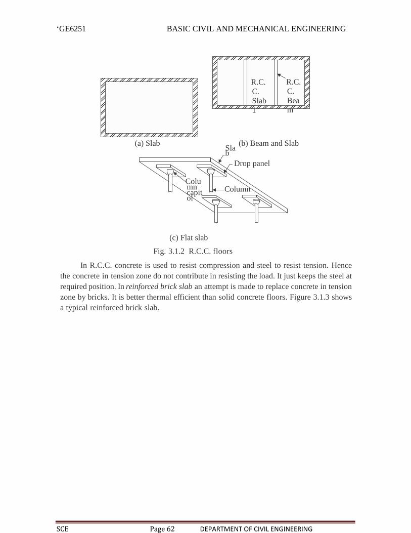
‘GE6251 BASIC CIVIL AND MECHANICAL ENGINEERING
SCE Page 62 DEPARTMENT OF CIVIL ENGINEERING
R.C.C.Slab1
R.C.C.Beam
(a) Slab (b) Beam and SlabSlab
Drop panel
Columncapitol
Column
(c) Flat slab
Fig. 3.1.2 R.C.C. floors
In R.C.C. concrete is used to resist compression and steel to resist tension. Hencethe concrete in tension zone do not contribute in resisting the load. It just keeps the steel atrequired position. In reinforced brick slab an attempt is made to replace concrete in tensionzone by bricks. It is better thermal efficient than solid concrete floors. Figure 3.1.3 showsa typical reinforced brick slab.

‘GE6251 BASIC CIVIL AND MECHANICAL ENGINEERING
SCE Page 63 DEPARTMENT OF CIVIL ENGINEERING
Reinforced cement concrete
40mm
Fig. 3.1.3 Reinforcedbrick slab
In ribbed or hollow tiled flooring, the concrete in tension portion is replaced byhollow tiles. Figure 3.1.2 shows a typical floor of this type.
Distributionreinforcement
Hollowtile
Main reinforcement
Fig. 3.1.2 Ribbed or Hollow tiled flooring
In precast concrete floor panels may be used which helps in avoiding form works,storing of sand, coarse aggregates etc. at the site and also curing. Factories manufacturethese units which are to be placed over supports in the structure. Figure 3.1.4 shows thecross-section of a typical precast floor unit. These units are available in 0.25 m widths andin various spans. Interlocking grooves are providedon the sides to get tight connection with adjoining units.
Support rodsfig. 3.1.4. Precast floor unit
Interlockinggroove

‘GE6251 BASIC CIVIL AND MECHANICAL ENGINEERING
SCE Page 64 DEPARTMENT OF CIVIL ENGINEERING
3.1 RoofRoof is the upper most portion of the building which protects the building from rain,wind and sun. Various types of roofs used may be divided broadly into three types:
1. Flat roofs 2. Pitched roofs
3. Shells and folded plates.Flat roofs are used in plains where rainfall is less and climate is moderate. Pitched roofsare preferred wherever rainfall is more. Shells and folded plate roofs are used to coverlarge column free areas required for auditoriums, factories etc. Brief description of theseroofs is presented below:
1. Flat Roofs: These roofs are nearly flat. However slight slope (not more than 10°) isgiven to drain out the rain water. All types of upper storey floors can serve as flat roofs.Many times top of these roofs are treated with water proofing materials-like mixing waterproofing chemicals in concrete, providing coba concrete. With advent of reliable waterproofing techniques such roofs are constructed even in areas with heavy rain fall.
The advantages of flat roofs are:(a) The roof can be used as a terrace for playing and celebrating functions.
(b) At any latter stage the roof can be converted as a floor by adding another
storey.
(c) They can suit to any shape of the building.
(d) Over-head water tanks and other services can be located
easily.
(e) They can be made fire proof easily compared to pitched roof.
The disadvantages of flat roofs are:(a) They cannot cover large column free areas.
(b) Leakage problem may occur at latter date also due to development of cracks. Onceleakage problem starts, it needs costly treatments.
(c) The dead weight of flat roofs is more.
(d) In places of snow fall flat roofs are to be avoided to reduce snow
load.
(e) The initial cost of construction is more.
(f) Speed of construction of flat roofs is less.
Types of Flat Roofs:
All the types listed for upper floors can be used as flat roofs.
2. Pitched Roofs: In the areas of heavy rain falls and snow fall sloping roof are used. Theslope of roof shall be more than 10°. They may have slopes as much as 45° to 60° also. Thesloped roofs are known as pitched roofs. The sloping roofs are preferred in large spannedstructures like workshops, factory buildings and ware houses. In all these roofs coveringsheets like A.C. sheet, G.I. sheets, tiles, slates etc. are supported on suitable structures.

‘GE6251 BASIC CIVIL AND MECHANICAL ENGINEERING
SCE Page 65 DEPARTMENT OF CIVIL ENGINEERING
The pitched roofs are classified into
(a) Single roofs(b) Double or purlin roofs
(c) Trussed roofs.(a) Single Roof: If the span of roof is less than 5 m the following types of single roofsare used.
(i) Lean to roofs(ii) Coupled roofs
(iii) Coupled-close roof
(iv) Collar beam roof
In all these roofs rafters placed at 600 mm to 800 mm spacing are main members takingload of the roof. Battens run over the rafters to support tiles. Figure 8.13 shows varioustypes of single roofs.
(a) Lean to roof (b) Coupled roof
Ridge piece
Ridge piece Rafters
Rafters
Wall plate Wallplate
Tiebeam
Eavesboard
Wall plate Wallplate
Collarbeam
Eaves
(c) Coupled close roof (d) Collarbeam roof board
Fig.3.1.5. Single roofs

‘GE6251 BASIC CIVIL AND MECHANICAL ENGINEERING
SCE Page 66 DEPARTMENT OF CIVIL ENGINEERING
(b) Double or Purlin Roofs: If span exceeds, the cost of rafters increase and single roofbecomes uneconomical. For spans more than 5 m double purlin roofs are preferred. Theintermediate support is given to rafters by purlins supported over collar beams. Figure 3.1.6shows a typical double or purlin roof.
Ridgepiece
Purlins Rafter
Wall plate Wallplate
Collar beamFig. 3.1.6 Double or purlins roofs W
all Eavesboard

‘GE6251 BASIC CIVIL AND MECHANICAL ENGINEERING
SCE Page 67 DEPARTMENT OF CIVIL ENGINEERING
(c) Trussed Roof: If span is more, a frame work of slender members are used to supportsloping roofs. These frames are known as trusses. A number of trusses may be placedlengthwise to get wall free longer halls. Purlins are provided over the trusses which in turnsupport roof sheets. For spans up to 9 m wooden trusses may be used but for larger
spans steel trusses are a must. In case of wooden trusses suitable carpentry joints are madeto connect various members at a joint. Bolts and straps are also used. In case of steeltrusses joints are made using gusset plates and by providing bolts or rivets or welding.
Depending upon the span, trusses of different shapes are used. End of trusses are supportedon walls or on column. Figure 3.1.7 shows different shapes of trusses used.
(a) King post spans up to 8 m(b) Queen post spans up to 10 m
(c) Howe truss with 4 and 8 panels spans 6 m to 30 m
(d) Pratt truss spans 6 m to 100 m Modified pratt truss
(e) Fink or french roof trusses spans up to 10 m
(f) Compoundfrench trussspan 20 m to30 m
Cambered frenchroof truss span20 m to 30 m
(g) Fan truss spans 10 m to 15 m (h) North light roof truss span 8 mto 10 m

‘GE6251 BASIC CIVIL AND MECHANICAL ENGINEERING
SCE Page 68 DEPARTMENT OF CIVIL ENGINEERING
3. Shells and Folded Plate Roofs: Shell roof may be defined as a curved surface, thethickness of which is small compared to the other dimensions. In these roofs lot of load istransferred by membrane compression instead of by bending as in the case of conventionalslab and beam constructions. Caves are having natural shell roofs. An examination of placesof worships built in India, Europe and Islamic nations show that shell structures were inusage for the last 800 to 1000 years. However the shells of middle ages were massivemasonry structures but nowadays thin R.C.C. shell roofs are built to cover large columnfree areas. Figure 3.1.8 shows commonly used shell roofs.
(a) Cylindrical (b) Butterfly (c) North light (d) Spherical dome
ParabolaParabola
(e) Paraboloid (f)Ellipsoidal
(g) Ellipticparaboloid [verticalsection parabolahorizontal sectionsellipse]
(h) Hyperbola ofrevolution
(i) Hyperbolicparaboloid[invertedumbrella type]
(j) Conoid (k) Corrugated shells (l) Funicular shell
Fig. 3.1.8 Types of shell roof
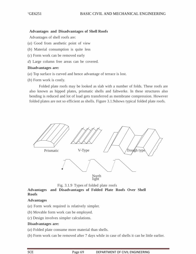
‘GE6251 BASIC CIVIL AND MECHANICAL ENGINEERING
SCE Page 69 DEPARTMENT OF CIVIL ENGINEERING
Advantages and Disadvantages of Shell Roofs
Advantages of shell roofs are:
(a) Good from aesthetic point of view
(b) Material consumption is quite less
(c) Form work can be removed early
d) Large column free areas can be covered.
Disadvantages are:
(a) Top surface is curved and hence advantage of terrace is lost.
(b) Form work is costly.
Folded plate roofs may be looked as slab with a number of folds. These roofs arealso known as hipped plates, prismatic shells and faltwerke. In these structures alsobending is reduced and lot of load gets transferred as membrane compression. Howeverfolded plates are not so efficient as shells. Figure 3.1.9shows typical folded plate roofs.
Prismatic V-Type Trough type
Northlight
Fig. 3.1.9 Types of folded plate roofsAdvantages and Disadvantages of Folded Plate Roofs Over ShellRoofs
Advantages
(a) Form work required is relatively simpler.
(b) Movable form work can be employed.
(c) Design involves simpler calculations.
Disadvantages are:
(a) Folded plate consume more material than shells.
(b) Form work can be removed after 7 days while in case of shells it can be little earlier.

‘GE6251 BASIC CIVIL AND MECHANICAL ENGINEERING
SCE Page 70 DEPARTMENT OF CIVIL ENGINEERING
3.1.1 Roof Coverings for PitchedRoofs
Various types of covering materials are available for pitched roofs and their selectiondepends upon the climatic conditions, fabrication facility, availability of materials andaffordability of the owner. Commonly used pitched roof covering materials are:
(a) Thatch (b) Shingle
(c) Tiles (d) Slates
(e) Asbestos cement (A.C.) sheets ( f ) Galvanised iron (G.I.) sheets
(a) Thatch Covering: These coverings are provided for small spans, mainly forresidential buildings in villages. Thatch is a roof covering of straw, reeds or similarmaterials. The thatch is well-soaked in water or fire resisting solution and packed bundlesare laid with their butt ends pointing towards eves. Thickness varies from 150 mm to 300mm. They are tied with ropes or twines to supporting structures. The supporting structureconsists of round bamboo rafters spaced at 200 mm to 300 mm over which split bambooslaid at right angles at close spacing. It is claimed that reed thatch can last 50 to 60 yearswhile straw thatch may last for 20–25 years.
The advantage of thatch roof is they are cheap and do not need skilled workers to buildthem. The disadvantages are they are very poor fire resistant and harbour rats and otherinsects.
(b) Shingles: Wood shingles are nothing but the split or sawn thin pieces of wood. Theirsize varies from 300 mm to 400 mm and length from 60 mm to 250 mm. Their thicknessvaries from 10 mm at one end to 3 mm at the other end. They are nailed to supportingstructures. They are commonly used in hilly areas for low cost housing. They have verypoor fire and termite resistance.
(c) Tiles: Various clay tiles are manufactured in different localities. They serve as goodcovering materials. Tiles are supported over battens which are in turn supported byrafters/trusses etc. Allahabad tiles, Mangalore tiles are excellent inter-locking tiles. Theygive good appearance also.
(d) Slates: A slate is a sedimentary rock. Its colour is gray. It can be easily split into thinsheets.Slates of size 450 mm to 600 mm wide, 300 mm long and 4 to 8 mm thick are usedas covering materials of pitched roofs in the areas where slate quarries are nearby. A goodslate is hard, tough, durable. They are having rough texture and they give ringing bell likesound when struck. They do not absorb water.
(e) A.C. Sheets: Asbestos cement is a material which consists of 15 per cent of asbestosfibres evenly distributed and pressed with cement. They are manufactured in sufficientlylarge size. The width of a A.C. sheet varies from 1.0 to 1.2 m and length from 1.75 to 3.0m. To get sufficient strength with thin sections they are manufactured with corrugation orwith traffords fib 3.20

‘GE6251 BASIC CIVIL AND MECHANICAL ENGINEERING
SCE Page 71 DEPARTMENT OF CIVIL ENGINEERING
They are fixed to the steel purlins using J-bolts. The roofing is quite economical,waterproof. However not very good thermal resistant. They are commonly used ascovering materials in ware houses, godowns or for larger halls. In auditorium etc., if thesesheets are used, false ceilings are provided to get good thermal resistance.
44 – 45 mm
1.05 m
Side lap
1.02m1.09m
NutG.l. washer
Steelpurlin
Purlin
3.2 Plastering
Applying mortar coats on the surfaces of walls, columns, ceiling etc. to get smooth finishis termed as plastering. Mortar used for plastering may be lime mortar, cement mortar orlime-cement mortar. Lime mortar used shall have fat lime to sand ratio of 1 : 3 or 1 : 4. Ifhydraulic lime is used mix proportion (lime: sand) is 1 : 2. Cement mortar of 1 : 4 or 1 : 6mix is very commonly used for plastering, richer mix being used for outer walls. Tocombine the cost effectiveness of lime mortar and good quality of cement mortar manyuse lime-cement mortar of proportion (cement : lime : sand) of 1 : 1 : 6 or 1 : 1 : 8or 1 : 2 : 8.
The objective of plastering are:
1. to conceal defective workmanship
2. to give smooth surface to avoid catching of dust.

‘GE6251 BASIC CIVIL AND MECHANICAL ENGINEERING
SCE Page 72 DEPARTMENT OF CIVIL ENGINEERING
3. to give good look.
4. to protect the wall from rain water and other atmospheric agencies.
5. to protect surfaces against vermit.
Requirement of good plaster are:
1. It should adhere to the background easily.
2. It should be hard and durable.
3. It should prevent penetration by moisture
4. It should be cheap.Lime mortar is usually applied in 3 coats while cement mortar is applied in two or
three coats for the stone and brick masonry. For concrete surfaces cement mortar maybe applied in two or three coats. For concrete building blocks many times only one coatof cement mortar is applied.
The first coat provides means of getting level surface. The final coat providessmooth surface. If three coats are used second coat is known as floating coat. Theaverage thickness of first coat is 10 to15 mm. Middle coat thickness is 6–8 mm. The final coat is just 2 to 3 mm thick. If singlecoat is used its thickness is kept between 6 to 12 mm. Such coats are used on concretesurfaces not exposed to rain.
3.3 Stress and strainWhen a body is subjected to a system of external forces, it undergoes a deformation. Atthe same time, by virtue of its strength, it offers a resistance against this deformation.This internal resistance offered by the body to counteract the applied load is called stress.
The resistance per unit cross sectional are is called stress. The deformation in unitoriginal dimension is termed as stain.
3.3.1Types of stresses and strains
Tensile stressWhen an external force produces elongation of the body in its direction, it is termed astensile force.
P= External tensile loadR= Resistane induced in the material of the bodyA=Cross sectional area
Tensile stress =Tensile load / Cross sectional are of the body
Tensile strain
Tensile strain =Increase in length/ Original length

‘GE6251 BASIC CIVIL AND MECHANICAL ENGINEERING
SCE Page 73 DEPARTMENT OF CIVIL ENGINEERING
Compressive stress
When an external force causes shortening of the body in the direction of force, it istermed as a compressive force. The stress developed in the body due to a compressiveforce is called as compressive stress.
P= External compressive loadR=Resistance induced in the material of the bodyA=Cross sectional area of the body
Compressive Stress = compressive load/ cross sectional area of the body
Compressive strain
Compressive strain = decrease in length/ Original length
Shear stress
When a body is subjected to two equal and opposite forces acting tangentially across theresisting section, as a result of which the body tends to shear off across the section, thenthis tangential force is termed as shear force and the stress induced is called shear stress.
Shear stress = Shear force/ Shear area
Shear strain
Shear strain =Transverse displacement/ Distance from the fixed base
Volumetric strain
The change in volume of an elastic body due to external force in unit original volume iscalled as the volumetric strain
Volumetric strain = dv/V
Lateral strain
When a material is subjected to uni-axial stress within the elastic limit, it deforms notonly longitudinally but also laterally. Under tension the lateral dimensions diminish andunder compression they increase. The lateral deformation per unit original lateraldimension is called lateral strain.

‘GE6251 BASIC CIVIL AND MECHANICAL ENGINEERING
SCE Page 74 DEPARTMENT OF CIVIL ENGINEERING
3.4 Elasticity
When an external force acts on a body, it undergoes some deformation. The property bywhich a body returns to its original shape after the removal of external load is elasticity.
3.4.1Elastic limit
The limiting value of stress up to and within which the entire deformation disappears onremoval of the external forces is called the elastic limit of the material. The body returnsto its original shape after the removal of the loading when the intensity of stress is withina certain limit. The limit is called elastic limit.
3.4.2Hooke’s law
Hooke’s law states that when an elastic material is stressed within elastic limit, the stressis proportional to the strain.K = stress/strain
3.4.3Young’s Modulus
The ratio of the axial stress to the corresponding axial strain, with in elastic limit is calledthe young’s modulus
E= Axial stress/Axial strain
3.4.4 Shear modulus
The ratio of the shear stress to the corresponding shear strain is a constant, which iscalled shear modulus
G = Shear stress/shear strain
3.4.5 Bulk Modulus
When a body is subjected to uniform direct stress in all the three mutually perpendiculardirection, the ratio of the direct stress to the corresponding volumetric strain is found tobe a constant which is called the bulk modulus
K = direct Stress/ Volumetric Strain
3.4.6 Poisson’s ratio
Poisson’s ratio = Lateral strain/ Longitudinal Strain

‘GE6251 BASIC CIVIL AND MECHANICAL ENGINEERING
SCE Page 75 DEPARTMENT OF CIVIL ENGINEERING
3.4.7 Relation between elastic constants
E =2G ( 1+r)
E=3K (1-2r)
E = 9KG/ 3 K +G
E= Young’s modulus
G= Shear modulusK=Bulk modulusR= poisson’s ratio
3.4.8 Factor of safety
Factor safety = Ultimate stress/ Allowable stressProblem
1. A mild steel rod of 12mm diameter and 200 mm length elongates 0.085 mm under anaxial pull of 10kN. Determine the young’s modulus of the material.
Load P= 10KN
Cross sectional Area = (3.14 x 12 2)/4
Stress = 10000/113.1 = 88.4 N/mm2
Strain = 0.085/ 200 = 4.25 x10 -4
Young’s modulus = 88.4 / 4.25x 10-4 = 2.08 x 10⁻⁵ N/mm
2. A bar of 30 mm diameter is subjected to a pull of 60 kN. The measured extension ongauge length of 200 mm is 0.09 mm and the change in diameter is 0.0039 mm. Calculatethe Poisson’s ratio and the values of the three moduli.
Dia of bar d = 30mm
Area A= 3.14 x 302 = 706.86 mm2
Pull P = 60kNLength l = 200 mmChange in length = 0.09 mmChange in diameter = 0.0039mm
Stress = P/A = (60 x103)/ 706.86 = 84.9 N/mm2

‘GE6251 BASIC CIVIL AND MECHANICAL ENGINEERING
SCE Page 76 DEPARTMENT OF CIVIL ENGINEERING
Strain = P/E =84.9/ E
e = 0.09/200 = 0.00045
84.9/ E = 0.00045= 1.886 x 10⁵ N/mm2
Poisson’s ratio
1/m = 0.00013/0.00045 = 0.289
Modulus of rigidity
G = ( 1.886 x 10 5)/2(0.289 +1) = 7.3157 x 10 4 N/mm2
Bulk modulusK= (1.886 x10 5)/3 ( 1-(2 x 0.289) = 1.489 x 10 5 N/mm2
3.5 BRIDGES
INTRODUCTION
A bridge is a structure providing passage over an obstacle without closing the waybeneath.
The required passage may be for a road, a railway pedestrian or a canal of apipeline. The obstacle to be crossed may be river, a road, a railway or a valley.
3.5.1 CLASSIFICATION OF BRIDGES
Bridges can be classified into various types depending upon the following factors:
Materials used for construction : Under this category bridges may be classified as:
a) Timber bridges b) Masonry bridges
c) Steel bridges d) Reinforced cement concrete bridges
e) Pre-stressed concrete bridges f) Composite bridges
Alignment : Under this category, the bridge can be classified as
a) Straight or square bridges and b) Skew bridges
Straight or square are the bridges which are at right angles to the axis of the river.
Skew bridges are not at right angles to the axis of the river.
The Relative position of bridge floor: Under this category, the bridge and classified as
a) Deck bridge b) Semi through bridge and c) Through bridge
Deck bridges are the bridges whose floorings are supported at the top of the superstructure. Through bridges are the bridges whose floorings are supported at the bottom of
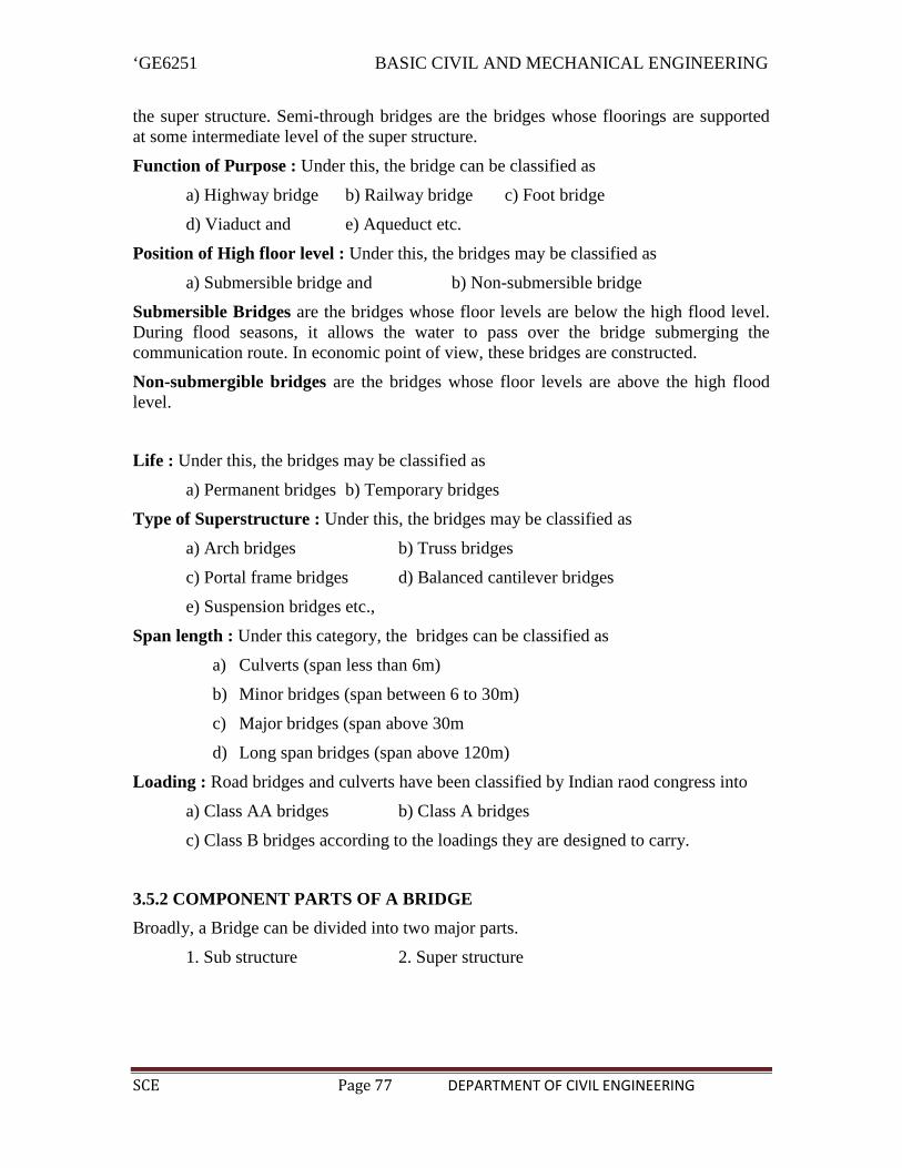
‘GE6251 BASIC CIVIL AND MECHANICAL ENGINEERING
SCE Page 77 DEPARTMENT OF CIVIL ENGINEERING
the super structure. Semi-through bridges are the bridges whose floorings are supportedat some intermediate level of the super structure.
Function of Purpose : Under this, the bridge can be classified as
a) Highway bridge b) Railway bridge c) Foot bridge
d) Viaduct and e) Aqueduct etc.
Position of High floor level : Under this, the bridges may be classified as
a) Submersible bridge and b) Non-submersible bridge
Submersible Bridges are the bridges whose floor levels are below the high flood level.During flood seasons, it allows the water to pass over the bridge submerging thecommunication route. In economic point of view, these bridges are constructed.
Non-submergible bridges are the bridges whose floor levels are above the high floodlevel.
Life : Under this, the bridges may be classified as
a) Permanent bridges b) Temporary bridges
Type of Superstructure : Under this, the bridges may be classified as
a) Arch bridges b) Truss bridges
c) Portal frame bridges d) Balanced cantilever bridges
e) Suspension bridges etc.,
Span length : Under this category, the bridges can be classified as
a) Culverts (span less than 6m)
b) Minor bridges (span between 6 to 30m)
c) Major bridges (span above 30m
d) Long span bridges (span above 120m)
Loading : Road bridges and culverts have been classified by Indian raod congress into
a) Class AA bridges b) Class A bridges
c) Class B bridges according to the loadings they are designed to carry.
3.5.2 COMPONENT PARTS OF A BRIDGE
Broadly, a Bridge can be divided into two major parts.
1. Sub structure 2. Super structure

‘GE6251 BASIC CIVIL AND MECHANICAL ENGINEERING
SCE Page 78 DEPARTMENT OF CIVIL ENGINEERING
1. SUB STRUCTURE
The function of the sub structure is similar to that of foundations, columns andwalls of a buildings, because it supports the super structure of the bridges and transmitsthe load safely to the ground.
The substructure consists of the following:
a. Abutments b. Piers c. Wing walls d. Approaches
e. Foundations for the piers and abutments
a. Abutments: The end of superstructure of a bridge is called abutments.
Its main functions are
1. To laterally support the earth work of the embankment of the approaches.
2. To transmit the load from the bridge superstructure.
3. To give final formation level to the bridge.
Bridge abutments can be made of brick masonry, stone masonry, plain concrete orreinforced concrete
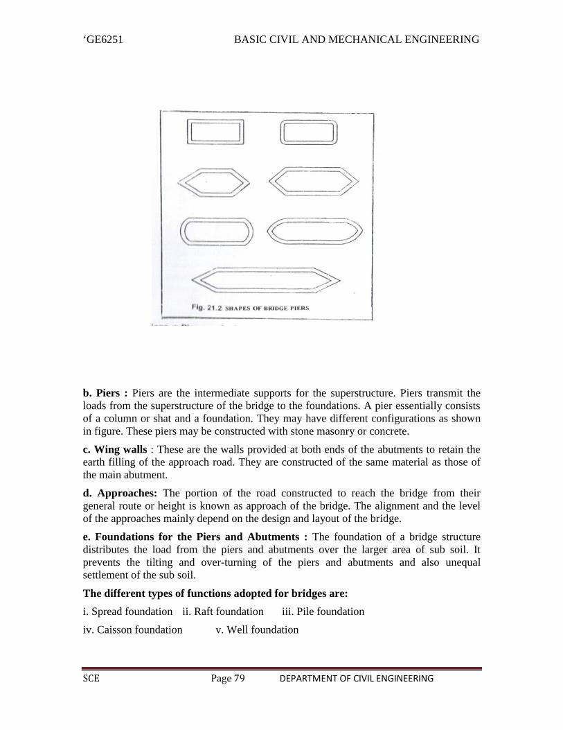
‘GE6251 BASIC CIVIL AND MECHANICAL ENGINEERING
SCE Page 79 DEPARTMENT OF CIVIL ENGINEERING
b. Piers : Piers are the intermediate supports for the superstructure. Piers transmit theloads from the superstructure of the bridge to the foundations. A pier essentially consistsof a column or shat and a foundation. They may have different configurations as shownin figure. These piers may be constructed with stone masonry or concrete.
c. Wing walls : These are the walls provided at both ends of the abutments to retain theearth filling of the approach road. They are constructed of the same material as those ofthe main abutment.
d. Approaches: The portion of the road constructed to reach the bridge from theirgeneral route or height is known as approach of the bridge. The alignment and the levelof the approaches mainly depend on the design and layout of the bridge.
e. Foundations for the Piers and Abutments : The foundation of a bridge structuredistributes the load from the piers and abutments over the larger area of sub soil. Itprevents the tilting and over-turning of the piers and abutments and also unequalsettlement of the sub soil.
The different types of functions adopted for bridges are:
i. Spread foundation ii. Raft foundation iii. Pile foundation
iv. Caisson foundation v. Well foundation

‘GE6251 BASIC CIVIL AND MECHANICAL ENGINEERING
SCE Page 80 DEPARTMENT OF CIVIL ENGINEERING
2. Super structure : The super structure is that part of the bridge over which the trafficmoves with safely.
It consists of:
a. Decking b. Parapet or hand rails, guard stones etc. c. Bearing
a. Decking : It is provided to allow the road surface to be built in over it. It may consistof a slab, trusses, arches etc.
b. Parapet or Hand rails, guard stones: These are the protective works provided onboth sides of the deck along the roadway in order to safe guard the moving vehicles andthe passengers on a bridge. Foot paths are also provided for pedestrians to walk along thebridge. In order to prevent a vehicle from striking the parapet wall of the hand rails, guardstones painted white are provided at the ends of the road surfaces.
c. Bearing: It is part of the bearing structure provided to distribute the load coming fromthe superstructure and also to allow for longitudinal and angular movements.
3.6 DAMS
3.6.1 INTRODUCTION
A dam is an impervious barrier construction across a river to store water. The sideon which water gets collected is called the upstream side, and the other side of the barrieris called the downstream side. The lake of water which is collected in the upstream side iscalled as reservoir. This water is then utilized as and when it is needed.
3.6.2 PURPOSE OF A DAM
1. To store and control the water for irrigation
2. To store and divert the water for domestic uses
3. To supply water for Industrial uses
4. To develop hydroelectric power plant to produce electricity
5. To increase water depths for navigation
6. To create storage space for flood control
7. To preserve and cultivate the useful aquatic life
8. For recreational purposes.
Multipurpose Reservoirs
A reservoir planned and constructed to serve not only one purpose but variouspurposes together is called a multipurpose reservoir.
Reservoir, designed for one purpose, incidentally serving other purposes, shall notbe called a multipurpose reservoir.
Hence a reservoir designed to protect the down stream areas from floods and alsoto conserve water for water supply, irrigation, industrial needs, hydroelectric purposesetc. shall be called as MULTIPURPOSE RESERVOIR.

‘GE6251 BASIC CIVIL AND MECHANICAL ENGINEERING
SCE Page 81 DEPARTMENT OF CIVIL ENGINEERING
3.6.3 FACTORS GOVERNING SELECTION OF SITE FOR DAM
1. Suitable foundations should be available at the site selected for a particular type adam. For gravity dams, sound rock is essential. For earth dams, any type offoundations is suitable with proper treatment.
2. The river cross-section at the dam site should preferably have a narrow gorge toreduce the length of the dam. However, the gorge should open out u/s to providelarge basin for a reservoir.
3. The general bed level at dam site should preferably be higher than that of the riverbasin. This will reduce the height of the dam and will facilitate the drainage.
4. A suitable site for the spillway should be available in the near vicinity. If thespillway is to be combined with the dam, the width of the George should be suchas to accommodate both.
5. Materials required for the construction should be easily available, either locally orin the near vicinity, so that the cost of transporting them is as low as possible.
6. The reservoir basin should be reasonably water tight. The stored water should notescape out through its side walls and bed.
7. The value of land and property submerged by the proposed site should be as lowas possible.
8. The dam site should be easily accessible so that it can be economically connectedto important towns and cities by rails, roads, etc.
9. To establish site for labour colonies, a healthy environment should be available inthe near vicinity.
3.6.4 CLASSIFICATION OF DAMS
Dams may be classified into different categories, depending upon the basis of theclassification.
(a) Classification according to use : Based on use, dams are classified as follows:
i. Storage dam ii. Diversion dam iii. Detention dam
i. Storage Dam : Storage dam is constructed to store water to its upstreamside during the periods of excess supply in the river (i.e. during rainy season) and is usedin periods of deficient supply.
ii. Diversion Dam : Diversion dam supply raises the water level slightly in theriver and thus provides head for carrying or diverting water into ditches, canals or otherconveyance systems to the place of use.
iii. Detension Dam : A detention dam is constructed to store water during floodsand release it gradually at a safe rate when the flood reduces.
(b) Classification According to Hydraulic Design : According tohydraulic design, dams may be classified as follows :

‘GE6251 BASIC CIVIL AND MECHANICAL ENGINEERING
SCE Page 82 DEPARTMENT OF CIVIL ENGINEERING
i. Non – Overflow dam ii. Overflow dam
i. Non-Overflow Dam :
A non-overflow dam is the one in which the top of the dam is kept at a higherelevation than the maximum expected high flood level.
ii. Over Flow Dam :
An overflow dam is the one which is designed to carry surplus discharge(including floods) over its crest.
Usually, in a river valley project, the two types of dams are combined. The maindam is kept as a non – overflow dam and some portion of dam is kipt as overflow dam(spill way)at some suitable location along the main dam.
c) Classification according to material : According to this classification, dam may beclassification, dam may be classified as follows : i. Rigid dam ii. Non-rigid dam
i. Rigid Dams : Rigid dams are those which are constructed of rigid materials suchas masonry, concrete, steel or timber. Rigid dams may be further classified as follows:
1. Solid Masonry gravity dam
2. Solid concrete gravity dam
3. Arched masonry dam
4. Arched concrete dam
5. Concrete buttress dam
6. Steel dam

‘GE6251 BASIC CIVIL AND MECHANICAL ENGINEERING
SCE Page 83 DEPARTMENT OF CIVIL ENGINEERING
7. Timber dam
ii. Non-Rigid Dams : Non-rigid dams are those which are constructed of non-rigidmaterials such as earth and or rockfill. The most common types of non-rigid dams are :
1. Earth dam 2. Rockfill dam
Gravity dams : A gravity dam is the one in which the external forces (such as waterpressure, wave pressure, silt pressure, uplift pressure etc.) are resisted by the weight ofthe dam itself. A gravity dam may be constructed either of masonry or of concrete.Masonry gravity dams are now-a-days constructed of only small heights. All major andimportant gravity dams are now constructed of concrete only. A gravity dam may beeither straight or curved in plan.
Arch dams : An arch dam is a dam curved in plan and carries a major part of itswaterload horizontally to the abutments by arch action. The thrust developed by the waterload carried by arch action essentially require strong side walls of the canyon to resist thearch forces. The weight of arch dams is not counted on to assist materially in theresistance of external loads.

‘GE6251 BASIC CIVIL AND MECHANICAL ENGINEERING
SCE Page 84 DEPARTMENT OF CIVIL ENGINEERING
Butter Dams :
A buttress dam consists of a number of buttresses of piers. These piers divide thespace (i.e. the space to be dammed) into number of spans. Between these piers, panelsare constructed of horizontal arches or flat slabs. When the panels consist or arches, it isknown as Multiple arches type buttress dam. If the panels consist of flat slab, it isknown as Deck type buttress dam.
Steel Dams : Steel dams are constructed with a frame work of steel with a thin skin plateas deck slab, on the upstream side. Steel dams are generally of two types.
i. Direct Strutted type
ii. Cantilever type
In the direct strutted type, the load on the deck plate is carried directly to thefoundation through inclined struts. In the cantilever type, the deck is formed by acantilever truss i.e. the deck is anchored to the foundation at the u/s toe.
Timber Dams : A timber dam is constructed of framework of timber struts andbeams, with timber plan facing to resist water pressure. They are suitable in places wheretimber can be available in plenty.
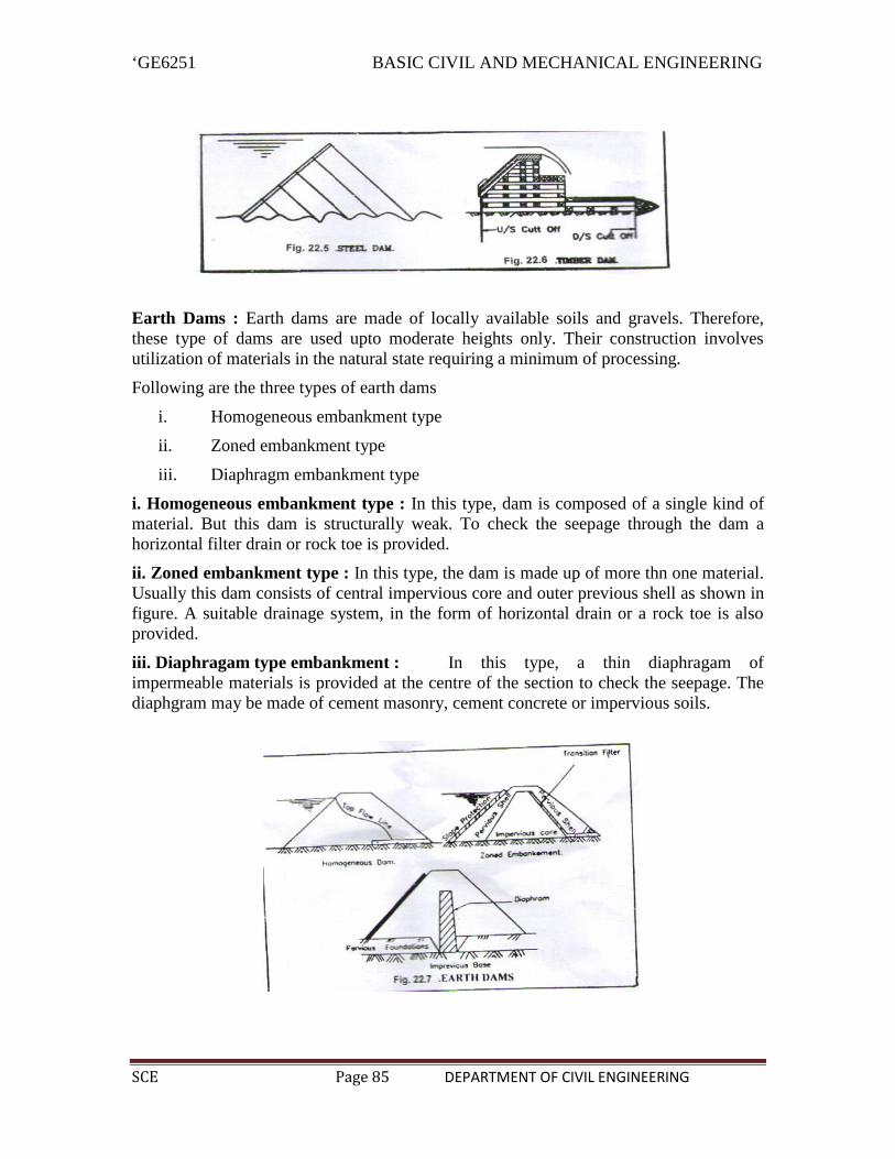
‘GE6251 BASIC CIVIL AND MECHANICAL ENGINEERING
SCE Page 85 DEPARTMENT OF CIVIL ENGINEERING
Earth Dams : Earth dams are made of locally available soils and gravels. Therefore,these type of dams are used upto moderate heights only. Their construction involvesutilization of materials in the natural state requiring a minimum of processing.
Following are the three types of earth dams
i. Homogeneous embankment type
ii. Zoned embankment type
iii. Diaphragm embankment type
i. Homogeneous embankment type : In this type, dam is composed of a single kind ofmaterial. But this dam is structurally weak. To check the seepage through the dam ahorizontal filter drain or rock toe is provided.
ii. Zoned embankment type : In this type, the dam is made up of more thn one material.Usually this dam consists of central impervious core and outer previous shell as shown infigure. A suitable drainage system, in the form of horizontal drain or a rock toe is alsoprovided.
iii. Diaphragam type embankment : In this type, a thin diaphragam ofimpermeable materials is provided at the centre of the section to check the seepage. Thediaphgram may be made of cement masonry, cement concrete or impervious soils.

‘GE6251 BASIC CIVIL AND MECHANICAL ENGINEERING
SCE Page 86 DEPARTMENT OF CIVIL ENGINEERING
Rock fill dams : In this type, variable sizes of rocks are used to form theembankment. The rock fill dam usually consists of the following four parts.
i. Main rock fill at the down – stream side
ii. Up - stream rock – cushion of laid – up stone.
iii. Up – stream impervious membrane resting on the upstream rock cushion.
iv. Up stream cut-off to check the sub soil seepage
Basics of Interior Design and Landscaping
Interior design means successful renovation to make cosmetic improvements, notstructural improvements, to house
An interior designer is a person who is considered a professional in the field of interiordesign or one who designs interiors as part of their job.
Interior designing is a practice concerned with anything that is found inside a space-walls, windows, door, finishes, and textures. Light etc. All of these elements are used byinterior designers to develop a functional, safe, and aesthetically pleasing space for abuilding’s user.They plan the spaces of almost every type of building including hotels, corporate spaces,schools, hospitals, private residence, shopping malls etc. Today, interior designers mustbe attuned to architectural detailing including: floor plans, home renovations, andconstruction codes.
3.7 Basics of interior design
Guidelines:A successful room is functionalA successful room expresses a moodA successful room exhibits a sense of harmony

‘GE6251 BASIC CIVIL AND MECHANICAL ENGINEERING
SCE Page 87 DEPARTMENT OF CIVIL ENGINEERING
FunctionA room must serve it’s intended function. No matter how beautifully you decorate aroom, if your scheme can’ fulfill all the functions you require the room to perform, thenthen the room has failed. If a dining room is not convenient to eat in, then Fails.MoodMood refers to the general look or feeling you want the room to express. The colourschemens, furniture, window treatments, floor treatments and lighting styles etc.
HarmonyAll the separate elements in a room must work together in harmony.all elements shouldfeel appropriate and nothing should feel out of place. Every element should beharmonious in mood, scale, quality and color. The scale must also be harmonious, thismeans all elements should be the same scale as each other and the same scale of the roomitself. No huge chairs with small chairs etc. The quality also needs to be harmonious. Ifyou are using expensive high quality furniture then don’t use them with cheap lookingcurtains etc. And lastly the color schemes must be harmonious. The color schemes inyour furniture must not clash with the color schemes in your rug etc.
Steps for designing room Sketching a room Drawing a floor plan Furniture layout Lighting plan.
LandscapingLandscaping refers to any activity that modifies the visible features of an area of land,including but not limited to:Living elements such as flora or what is commonly referred to as Gardening, the art andCraft of growing plants with a goal of creating a beautiful environment within thelandscapeNatural elements such as landforms, terrain shape and elevationHuman elements such as structures, buildings,fences or other material objects createdand installed by humansAbstract elements such as the weather and lighting conditions.
Lanscaping is both science and art, and reqires good observation and design skills. Agood landscaper understands the elements of nature and construction and blends themaccordingly
Landscape design
Landscape design is similar to landscape architecture. Landscape design focuses more onthe artistic merits of design, while landscape Architecture encompasses the artistic designas well as structural engineering.
‘GE6251 BASIC CIVIL AND MECHANICAL ENGINEERING
SCE Page 88 DEPARTMENT OF CIVIL ENGINEERING
Traditionally, landscape designers and architects have used pencil and paper o plot theposition of plants and other landscape features.
Basic element of landscaping Unity Simplicity Balance Focalization
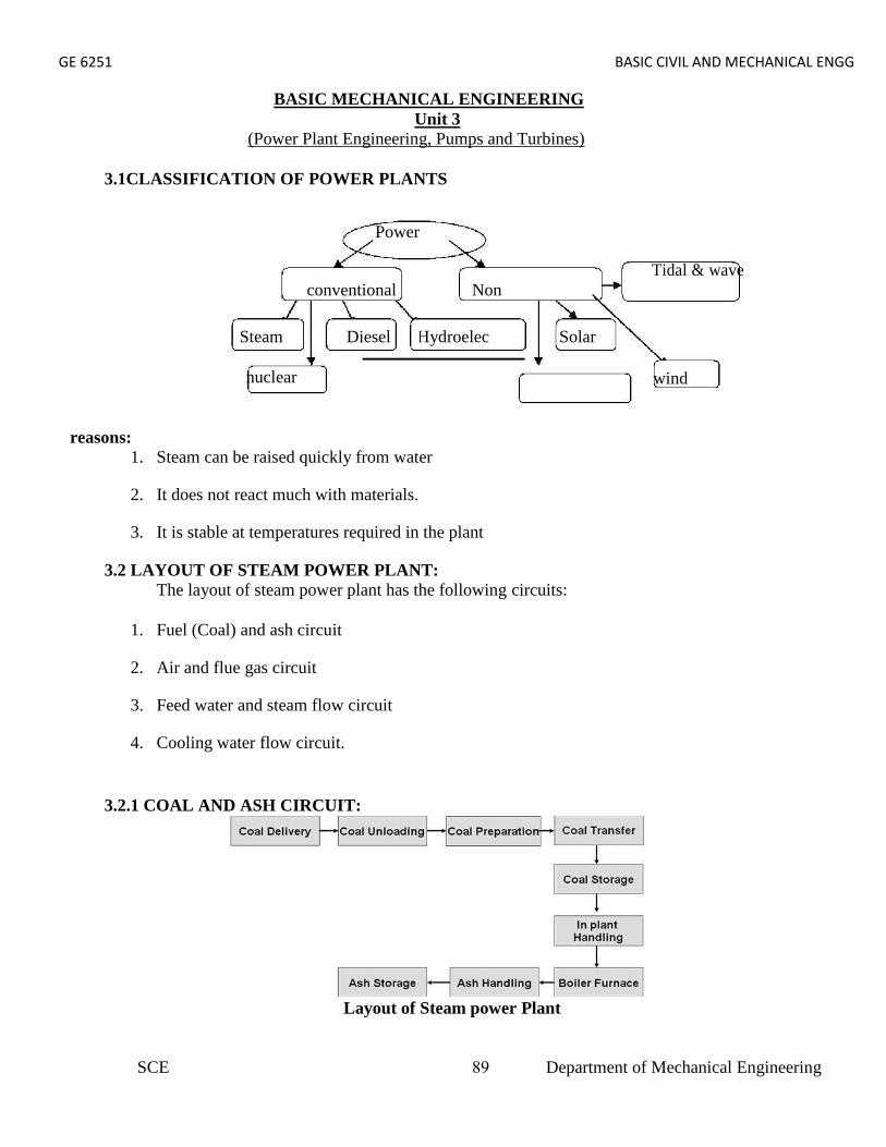
GE 6251 BASIC CIVIL AND MECHANICAL ENGG
BASIC MECHANICAL ENGINEERINGUnit 3
(Power Plant Engineering, Pumps and Turbines)
3.1CLASSIFICATION OF POWER PLANTS
1. Steam can be raised quickly from water
2. It does not react much with materials.
3. It is stable at temperatures required in the plant
3.2 LAYOUT OF STEAM POWER PLANT:The layout of steam power plant has the following circuits:
1. Fuel (Coal) and ash circuit
2. Air and flue gas circuit
3. Feed water and steam flow circuit
4. Cooling water flow circuit.
3.2.1 COAL AND ASH CIRCUIT:
Layout of Steam power Plant
Power
conventional NonTidal & wave
Steam Diesel Hydroelec Solar
nuclear wind
reasons:
SCE 89 Department of Mechanical Engineering
GE 6251 BASIC CIVIL AND MECHANICAL ENGG
Coal and Ash Circuit:• Coal from mines is delivered by ships, rails or trucks to the power station.
• Coal received at coal yard.•• Coal is sized by crushers, breakers etc.,
• The sized coal is stored in coal storage.
• From stock yard, the coal is transferred to the boiler furnace by means of conveyors,elevators etc.,
• The coal is burnt in the boiler and ash is formed.
• Ash coming out of the furnace will be too hot, dusty and accompanied by poisonousgases.
• The ash is transferred to the ash storage.
• Generally the ash will be quenched to reduce the temperature and the dust content.
3.2.2 AIR AND FLUE GAS CIRCUIT:• Air is taken from the atmosphere by the action of FD fan.
• It is passed through an air pre heater
• The air is preheated by the flue gases in the pre heater.
• This preheated air is supplied to the furnace to aid the combustion of fuel.
• Due to the combustion of fuel the flue gases are formed.
• The flue gases from the furnace pass over the boiler tubes and super heater tubes.
• Then the flue gases pass through economiser to heat the feed water.
• After that it passes through a dust collector.
It is then exhausted to atmosphere through chimney
SCE 90 Department of Mechanical Engineering

GE 6251 BASIC CIVIL AND MECHANICAL ENGG
SCE 3 Department of Mechanical Engineering
3.2.3 WATER AND STEAM CIRCUIT
Layout of Steam Power PlantWater and Steam Circuit:
• The water is preheated by the flue gases in the economiser.
• This preheated water is then supplied to the boiler drum.
• Heat is transferred to the water by the burning of the coal.
• Due to this, water is converted into the steam.
• The steam raised in boiler is passed through a super heater.
• It is superheated by the flue gases.
• The turbine drives generator to produce electric power.
• The expanded steam is then passed through the condenser.
• In the condenser, steam is condensed into water there circulated.
3.2.4 COOLING WATER CIRCUIT:• The exhaust steam from the turbine is condensed in the condenser.
• In the condenser, the cold water is circulated to condense the steam into water.
• The steam is condensed by losing its latent heat to the circulating the cold water.
• Hence the cold water gets heated.
• This hot water is then taken to a cooling tower.
• In cooling tower the water is sprayed in the form of droplets through nozzles.
• The atmospheric air enters the cooling tower from the openings provided at thebottom of the tower.
GE 6251 BASIC CIVIL AND MECHANICAL ENGG
3.2.3 WATER AND STEAM CIRCUIT
Layout of Steam Power PlantWater and Steam Circuit:
• The water is preheated by the flue gases in the economiser.
• This preheated water is then supplied to the boiler drum.
• Heat is transferred to the water by the burning of the coal.
• Due to this, water is converted into the steam.
• The steam raised in boiler is passed through a super heater.
• It is superheated by the flue gases.
• The turbine drives generator to produce electric power.
• The expanded steam is then passed through the condenser.
• In the condenser, steam is condensed into water there circulated.
3.2.4 COOLING WATER CIRCUIT:• The exhaust steam from the turbine is condensed in the condenser.
• In the condenser, the cold water is circulated to condense the steam into water.
• The steam is condensed by losing its latent heat to the circulating the cold water.
• Hence the cold water gets heated.
• This hot water is then taken to a cooling tower.
• In cooling tower the water is sprayed in the form of droplets through nozzles.
• The atmospheric air enters the cooling tower from the openings provided at thebottom of the tower.
SCE 91 Department of Mechanical Engineering
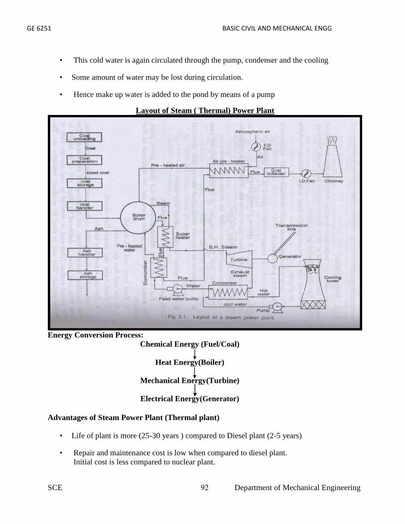
GE 6251 BASIC CIVIL AND MECHANICAL ENGG
• This cold water is again circulated through the pump, condenser and the cooling
• Some amount of water may be lost during circulation.
• Hence make up water is added to the pond by means of a pump
Layout of Steam ( Thermal) Power Plant
Energy Conversion Process:Chemical Energy (Fuel/Coal)
Heat Energy(Boiler)
Mechanical Energy(Turbine)
Electrical Energy(Generator)
Advantages of Steam Power Plant (Thermal plant)
• Life of plant is more (25-30 years ) compared to Diesel plant (2-5 years)
• Repair and maintenance cost is low when compared to diesel plant.Initial cost is less compared to nuclear plant.
SCE 92 Department of Mechanical Engineering

GE 6251 BASIC CIVIL AND MECHANICAL ENGG
• Suitable for varying load conditions.
• No radioactive harmful wastes are produced
• Unskilled operators can operate the plant.
• The power generation does not depend on the water storage.
• There are no transmission losses, as they are located near load centres.
Disadvantages of thermal power plant:• Less efficient than diesel plants.
• Starting up and bringing into service takes more time.
• Cooling water required is more.
• Space required is more.
• Storage required for the fuel is more.
• Ash handling is a big problem
• Not economical in areas which are remote from coal fields.
• Manpower required is more.
• For large units, the capital cost is more.
3.3 LIST DOWN THE FACTORS TO BE CONSIDERED FOR SELECTION OF SITEFOR THERMAL POWER PLANT:
Availability of coal:• A thermal plant of 400M, capacity requires nearly 6000 tons of coal every day.
• Power plant should be located near coal mines.
Ash Disposal Facilities:• Ash comes out in hot condition and handling is difficult.
The ash can be disposed into sea or river.
Water Availability :• Water consumption is more as feed water into boiler, condenser and for ash disposal.
• Water is required for drinking purpose.
• Hence plant should be located near water source.
SCE 93 Department of Mechanical Engineering

GE 6251 BASIC CIVIL AND MECHANICAL ENGG
Transport Facility :Public Problems:
• The plant should be far away from residential area to avoid nuisance from smoke, fly ashand noise.
Nature of Land :• Many power plants have failed due to weak foundations.
• Land (soil) should have good bearing capacity to withstand dead load of plant.
Thermal power plants in T.N:Neyveli
TuticorinEnnoreMettur
Explain about the pollution caused by Thermal Power Plant (Steam Power Plant):
• Main pollutants from thermal plants are SO2, CO2, CO as minute particles such as fly ash.
• SO2 causes suffocation, irritation to throat and eyes and respiratory for people. It destroyscrop.
• CO is a poisonous gas.
• Dust particles cause respiratory troubles like cough, cold, sneezing etc.,
Thermal Pollution:• Thermal plants produce 40 million kJ of heat to the environment through condenser water
and exhaust gases.
• Thermal pollution of atmosphere can be reduced using the low grade energy exhaustedsteam.
Noise Pollution:• The sources of noise in a power plant are turbo alternators, fans and power transformers.
• Sound proofing can be done to reduce the noise.
3.4 GAS POWER PLANT• A gas power plant uses gas turbine as the prime mover for generating electricity.
• It uses natural gas or kerosene or benzene as fuel.
• Gas plant can produce only limited amount of the electricity.
• Efficiency of the plant is only 35%
• Generally a gas plant is expensive to operate.
SCE 94 Department of Mechanical Engineering

GE 6251 BASIC CIVIL AND MECHANICAL ENGG
• Hence it is usually installed with steam power plant in closed combined cycle.
• It is generally used in combination with steam/thermal power plant during peak load
• When the gas power plant is combined with thermal/steam power plant efficiency ofthe plant is up to 60% - 70%
Layout of the Gas turbine Power plant:
Combustion and generation of electricity:• Gas turbine draws clean air into through air filter from atmosphere, with the help of a
compressor.
• During the compression pressure of the air is increased.
• Compressed air is passed through to a combustion chamber along with fuel (Natural gas).
• The air fuel mixture is ignited at high pressure in the combustion chamber.
SCE 95 Department of Mechanical Engineering

GE 6251 BASIC CIVIL AND MECHANICAL ENGG
• Combustion takes place.
• The generated hot gas of compression is passed through the gas turbine.
• Hot gases expand, and the turbine blades are connected to the turbine shaft are rotated.
• The turbine shaft which is coupled to the shaft of the electrical generator at the other endalso rotates and drives the electrical generator.
• A portion of the energy developed by the hot gases through the gas turbine is used to runthe compressor.
• The residual hot gases from gas turbine are passed through a heat exchanger (heatrecovery steam generator)
• The heat exchanger produces steam with high pressure with the help of a steam boiler.
• The steam is allowed to expand in the steam turbine.
• when it passes through the turbine blades, the turbine shaft is rotated. The shaft iscoupled to the generator, which generates electricity.
• Gas turbine and steam turbine combination enables increased power generation.
Transmission and distribution :• The generated electricity from both gas and steam turbines is fed to the step up
transformer where its voltage is increased.
• Then the electricity is conveyed through transmission lines for distribution.
MERITS:Natural gas is readily available.
• Setting up cost can be reduced if the plant is installed near the source of natural gas.
• Less gas storage cost
• Less space occupation.
• Compared to steam power plant, smaller in size.
• Low operating cost.
• Low maintenance cost.
• No standby losses.
• Cheaper fuels like natural gas.
SCE 96 Department of Mechanical Engineering

GE 6251 BASIC CIVIL AND MECHANICAL ENGG
Demerits:
• Gas turbine has low thermal efficiency.
• Has starting problem.
• Efficient only in combined cycle configuration.
• Temperature of combustion chamber is too high, which results in shorter life time.
3.5 DIESEL POWER PLANT
3.5.1 WORKING OF DIESEL POWER PLANT:
• Air from atmosphere is drawn into the compressor and is compressed.
• The compressed air is sent to diesel engine through filter.
• In the filter, dust, dirt from air are filtered and only clean air is sent to diesel engine.
• Fuel oil from tank is passed through filter where it gets filtered and clean oil is injectedinto the diesel engine through fuel pump and fuel injector
• Mixture of compressed air and spray of fuel oil are ignited into the engine andcombustion takes place.
• The heat energy is utilized for driving the generator, which produces power.
SCE 97 Department of Mechanical Engineering
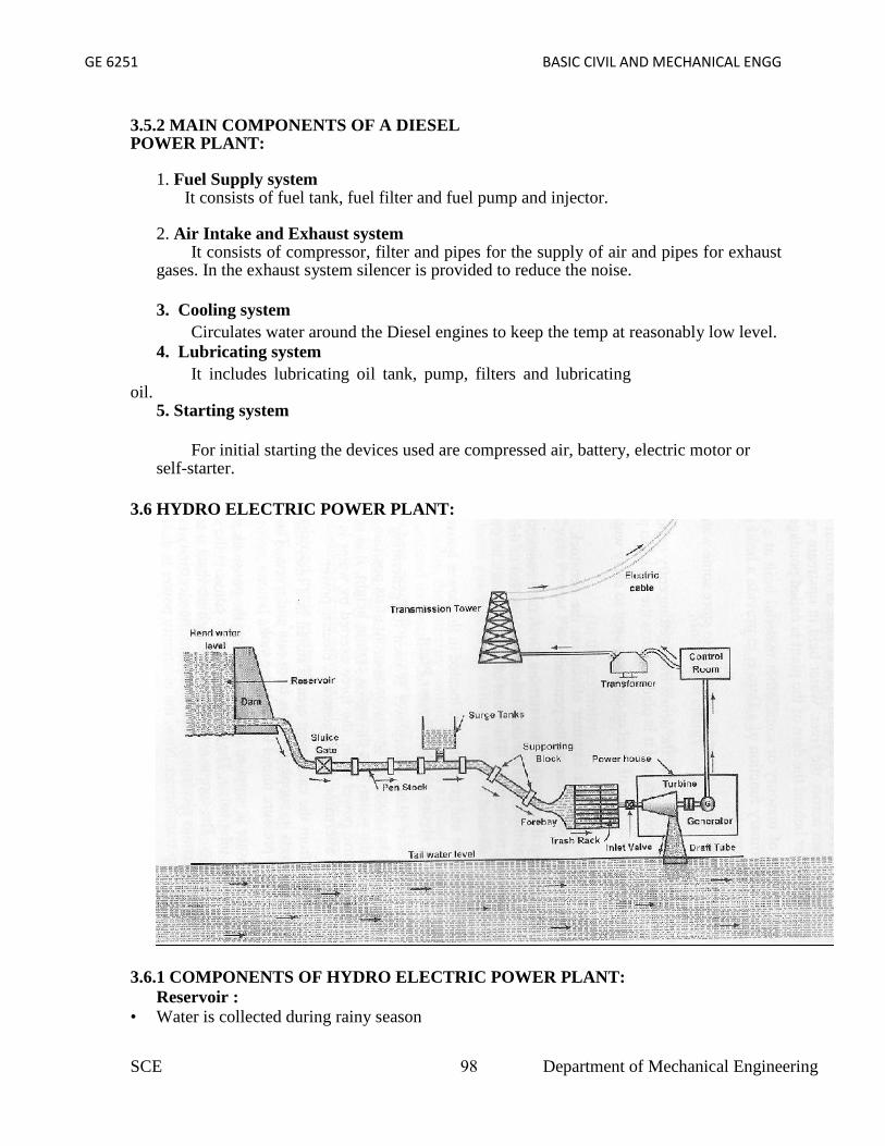
GE 6251 BASIC CIVIL AND MECHANICAL ENGG
3.5.2 MAIN COMPONENTS OF A DIESELPOWER PLANT:
1. Fuel Supply systemIt consists of fuel tank, fuel filter and fuel pump and injector.
2. Air Intake and Exhaust systemIt consists of compressor, filter and pipes for the supply of air and pipes for exhaust
gases. In the exhaust system silencer is provided to reduce the noise.
3. Cooling systemCirculates water around the Diesel engines to keep the temp at reasonably low level.
4. Lubricating systemIt includes lubricating oil tank, pump, filters and lubricating
oil.5. Starting system
For initial starting the devices used are compressed air, battery, electric motor orself-starter.
3.6 HYDRO ELECTRIC POWER PLANT:
3.6.1 COMPONENTS OF HYDRO ELECTRIC POWER PLANT:Reservoir :
• Water is collected during rainy season
SCE 98 Department of Mechanical Engineering

GE 6251 BASIC CIVIL AND MECHANICAL ENGG
• It is stored in the reservoir.
• A dam is built across the river adequate water head.
Penstock :• It is a passage through which water flows from reservoir to turbine.
Surge Tank :• It is installed along the penstock (between turbine and reservoir)
• To control or regulate the sudden water over flow and to protect the penstock frombursting.
• It reduces the pressure and avoids damage to the penstock due to the water hammereffect.
• When the load on the turbine is decreased there will be a back flow, which causesincrease or decrease in pressure. It is known as water hammer.
• Power House :
• It is building that houses that water turbine, generator, transformer and control room.
• Water Turbine:
• Water turbines such as Pelton, Kaplan and Francis are used to convert pressure andkinetic energy of flowing water into mechanical energy.
• Draft Tube:
• It is connected to the outlet of the turbine.
• Tailrace:
• It refers to the downstream level of water discharged from turbine.
• Generator :
• It is a machine used to convert mechanical energy into electrical energy.
• Step up transformer:
• It converts the Alternating Current (AC) into high voltage current suitable fortransmission.
SCE 99 Department of Mechanical Engineering

GE 6251 BASIC CIVIL AND MECHANICAL ENGG
3.6.2 WORKING PRINCIPLE OF HYDRO ELECTRIC POWER PLANT:
• It uses the potential energy of water of water stored in a reservoir.
• The water from the reservoir through a penstock and then forced through nozzle ornozzles before reaching the turbine.
• The hydraulic turbine converts the kinetic energy of water under pressure into mechanicalenergy.
• The shaft of the turbine is coupled to a generator that generates electricity
• The electricity generated is fed to the step-up transformer to increase its voltage.
• Power is fed to the transmission lines for distribution.
• The output power of Hydel power plant depends on the head of water stored in thereservoir and the quantity of water discharged
SCE 100 Department of Mechanical Engineering
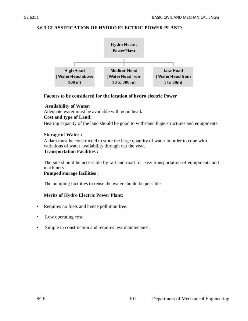
GE 6251 BASIC CIVIL AND MECHANICAL ENGG
3.6.3 CLASSIFICATION OF HYDRO ELECTRIC POWER PLANT:
Factors to be considered for the location of hydro electric Power
Availability of Water:Adequate water must be available with good head.Cost and type of Land:Bearing capacity of the land should be good to withstand huge structures and equipments.
Storage of Water :A dam must be constructed to store the large quantity of water in order to cope withvariations of water availability through out the year.Transportation Facilities :
The site should be accessible by rail and road for easy transportation of equipments andmachinery.Pumped storage facilities :
The pumping facilities to reuse the water should be possible.
Merits of Hydro Electric Power Plant:
• Requires no fuels and hence pollution free.
• Low operating cost.
• Simple in construction and requires less maintenance.
SCE 101 Department of Mechanical Engineering

GE 6251 BASIC CIVIL AND MECHANICAL ENGG
• Skilled personnel is required for construction.
• High cost of transmission as plant is normally required far off from hilly areas.
• Period of delay causes the delay in the commissioning of the plant.
• Construction of new hydel plant may need rehabilitation of people and paymentcompensation for land acquisition.
3.7 NUCLEAR POWER PLANT
SCE 102 Department of Mechanical Engineering

GE 6251 BASIC CIVIL AND MECHANICAL ENGG
Nuclear Power plant layout
• Nuclear power plant uses nuclear energy from radioactive elementfor generating electrical energy.
• More than 15% of the world’s electricity i
• It is generally located far away from populated areas.
• In future generation of electricity will be depending on Nuclear Power Plant, as it iseconomical.
• 1 kg of uranium U -235 can produce electrical power electrical that can beproduced by using 3000 -4500 tonnes of high grade coal or 2000 tonnesof oil.
SCE 103 Department of Mechanical Engineering

GE 6251 BASIC CIVIL AND MECHANICAL ENGG
3.7.1 COMPONENTS OF NUCLEAR POWER PLANT:
Nuclear Fuel :Normally used nuclear fuel is uranium (U235)
Fuel Rods:The fuel rods hold nuclear fuel in a nuclear power plant.Neutron Source: A source of neutron is required to initiate the fission for the first time. Amixture of beryllium with plutonium is commonly used as a source of neutron.
Reactor:• Nuclear fission takes place in the reactor only.
• Nuclear fission produces large quantity of heat.
• The heat generated in the reactor is carried by coolant circulated through the reactor.
Control Rods:• They are used to control the chain reaction.
• They are absorbers of neutrons.
• The commonly used control rods are made up of cadmium or boron.
Moderator:• Moderators are used to slow down the fast neutrons.
• It reduces 2 MeV to an average velocity of 0.025 eV.
• Ordinary or heavy water are used as moderators.
Fuel Rods:
• The fuel rods hold nuclear fuel in a nuclear power plant.
Neutron Reflectors:
• To prevent the leakage of neutrons to large extent.
• In PHWR, the moderator itself acts as reflectors.
Shielding:
• To protect from harmful radiations the reactor is surrounded b a concrete wall ofthickness about 2 to 2.5 m.
SCE 104 Department of Mechanical Engineering
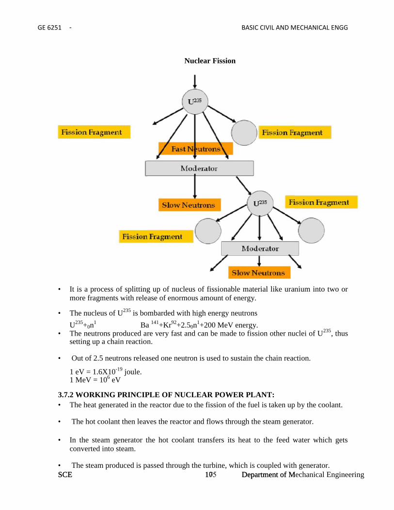
GE 6251 BASIC CIVIL AND MECHANICAL ENGG
SCE 17 Department of Mechanical Engineering
Nuclear Fission
• It is a process of splitting up of nucleus of fissionable material like uranium into two ormore fragments with release of enormous amount of energy.
• The nucleus of U235 is bombarded with high energy neutrons
U235+0n1 Ba 141+Kr92+2.50n
1+200 MeV energy.• The neutrons produced are very fast and can be made to fission other nuclei of U235, thus
setting up a chain reaction.
• Out of 2.5 neutrons released one neutron is used to sustain the chain reaction.
1 eV = 1.6X10⁻¹⁹ joule.1 MeV = 106 eV
3.7.2 WORKING PRINCIPLE OF NUCLEAR POWER PLANT:• The heat generated in the reactor due to the fission of the fuel is taken up by the coolant.
• The hot coolant then leaves the reactor and flows through the steam generator.
• In the steam generator the hot coolant transfers its heat to the feed water which getsconverted into steam.
• The steam produced is passed through the turbine, which is coupled with generator.
GE 6251 BASIC CIVIL AND MECHANICAL ENGG
Nuclear Fission
• It is a process of splitting up of nucleus of fissionable material like uranium into two ormore fragments with release of enormous amount of energy.
• The nucleus of U235 is bombarded with high energy neutrons
U235+0n1 Ba 141+Kr92+2.50n
1+200 MeV energy.• The neutrons produced are very fast and can be made to fission other nuclei of U235, thus
setting up a chain reaction.
• Out of 2.5 neutrons released one neutron is used to sustain the chain reaction.
1 eV = 1.6X10⁻¹⁹ joule.1 MeV = 106 eV
3.7.2 WORKING PRINCIPLE OF NUCLEAR POWER PLANT:• The heat generated in the reactor due to the fission of the fuel is taken up by the coolant.
• The hot coolant then leaves the reactor and flows through the steam generator.
• In the steam generator the hot coolant transfers its heat to the feed water which getsconverted into steam.
• The steam produced is passed through the turbine, which is coupled with generator.SCE 105 Department of Mechanical Engineering
GE 6251 BASIC CIVIL AND MECHANICAL ENGG
• Hence the power is produced during the running of turbine.
• The exhaust steam from the turbine is condensed in the condenser.
• The condensate then flows to the steam generator through the feed pump.
• The cycle is thus repeated.
Advantages of Nuclear Power Plant:• Requires less space compared to steam power plant.
• Fuel required is negligible compared to coal requirement.
• Fuel transport cost is less.
• Reliable in operation.
• Cost of erection is less.
• Water required is very less.
Disadvantages of Nuclear Power Plant:• Initial Cost is higher.
• Not suitable for varying load condition.
• Radioactive wastes are hazardous. Hence these are to be handled with much care.
• Maintenance cost is higher.
• Trained workers are required to operate the plant.
Nuclear Power Plants in India:• IGCAR, Kalpakkam in Chennai.
• Rana Pratap Sagar in Rajasthan
• Narora in Uttar Pradesh
• Kakarpur near Surat at Gujarat
3.8 PUMPS
• A pump is a machine which is used to raise or transfer the fluids.
• It is also used to maintain the constant flow rate or constant pressure.
• It is normally driven by a engine or a motor.
• Pumps are rated by the horse power.
SCE 106 Department of Mechanical Engineering
GE 6251 BASIC CIVIL AND MECHANICAL ENGG
3.8.1 CLASSIFICATION OF PUMPS:
It is classified into positive displacement pumps and roto dynamic pumps.
• In positive displacement pumps, fluid is drawn or forced into a finite space and it issealed.
• It is then forced out and the cycle is repeated.
In roto dynamic pumps, centrifugal force is used to move the fluid into a pipe.
3.8.2 RECIPROCATING PUMPS:• It is a positive displacement pump
• It uses a piston and cylinder arrangement with suction and delivery valves integratedwith the pump.
• It can be single acting and double acting
• There may be single or multi cylinders also.
• It is a positive displacement pump
• It sucks and raises the liquid by actually displacing it with a piston/plunger that executesa reciprocating motion in a closely fitting cylinder.
3.8.3 WORKING OF SINGLE ACTING RECIPROCATING PUMP: During suction stroke the piston moves to the left, causing the inlet valve to open. Water is admitted into the cylinder through the inlet valve.
During the discharge stroke the piston moves to the right closes the suction valve andopens the out let valve.
Through the outlet valve the volume of liquid moved out of the cylinder.
3.8.4 DOUBLE ACTING RECIPROCATING PUMP –WORKING:• Each cycle consists of two strokes.
• Both the strokes are effective, hence it is known as double acting pump
• Liquid is filled at one end and discharged at other end during forward stroke.
• During the return stroke, end of cylinder just emptied is filled and the end just filled isemptied.
SCE 107 Department of Mechanical Engineering

GE 6251 BASIC CIVIL AND MECHANICAL ENGG
3.9 AIR VESSELSAir vessel is a closed chamber containing compressed air in the upper part and liquidbeing pumped in the lower part.
3.9.1PURPOSE OF USING AN AIR VESSEL: To get continuous supply of liquid at a uniform rate.
To save the power required to drive the pump (By using an air vessel theacceleration and friction heads are considerably reduced)
To run the pump at much higher speed without any danger of separation.
Advantages of reciprocating pump:• Relatively compact design
• High viscosity performance
• Ability to handle high differential pressure.
SCE 108 Department of Mechanical Engineering

GE 6251 BASIC CIVIL AND MECHANICAL ENGG
SCE 21 Department of Mechanical Engineering
3.10 CENTRIFUGAL PUMPS
3.10.1 COMPONENTS OF CENTRIFUGAL PUMP:
A rotating component comprising of an impeller and a shaft. A stationery component comprising a volute (casing), suction and delivery pipe.
3.10.2 WORKING PRINCIPLE OF CENTRIFUGAL PUMP:Principle:
When a certain mass of fluid is rotated by an external source, it is thrown away fromthe central axis of rotation and a centrifugal head is impressed which enables it to rise toa higher level.
Working:
The delivery valve is closed and the pump is primed, so that no air pocket is left.
Keeping the delivery valve still closed the electric motor is started to rotate theimpeller.
The rotation of the impeller is gradually increased till the impeller rotates at itsnormal speed.
After the impeller attains the normal speed the delivery valve is opened when theliquid is sucked continuously upto the suction pipe.
It passes through the eye of the casing and enters the impeller at its centre.
The liquid is impelled out by the rotating vanes and it comes out at the outlet tips ofthe vanes into the casing.
GE 6251 BASIC CIVIL AND MECHANICAL ENGG
3.10 CENTRIFUGAL PUMPS
3.10.1 COMPONENTS OF CENTRIFUGAL PUMP:
A rotating component comprising of an impeller and a shaft. A stationery component comprising a volute (casing), suction and delivery pipe.
3.10.2 WORKING PRINCIPLE OF CENTRIFUGAL PUMP:Principle:
When a certain mass of fluid is rotated by an external source, it is thrown away fromthe central axis of rotation and a centrifugal head is impressed which enables it to rise toa higher level.
Working:
The delivery valve is closed and the pump is primed, so that no air pocket is left.
Keeping the delivery valve still closed the electric motor is started to rotate theimpeller.
The rotation of the impeller is gradually increased till the impeller rotates at itsnormal speed.
After the impeller attains the normal speed the delivery valve is opened when theliquid is sucked continuously upto the suction pipe.
It passes through the eye of the casing and enters the impeller at its centre.
The liquid is impelled out by the rotating vanes and it comes out at the outlet tips ofthe vanes into the casing.
SCE Department of Mechanical Engineering
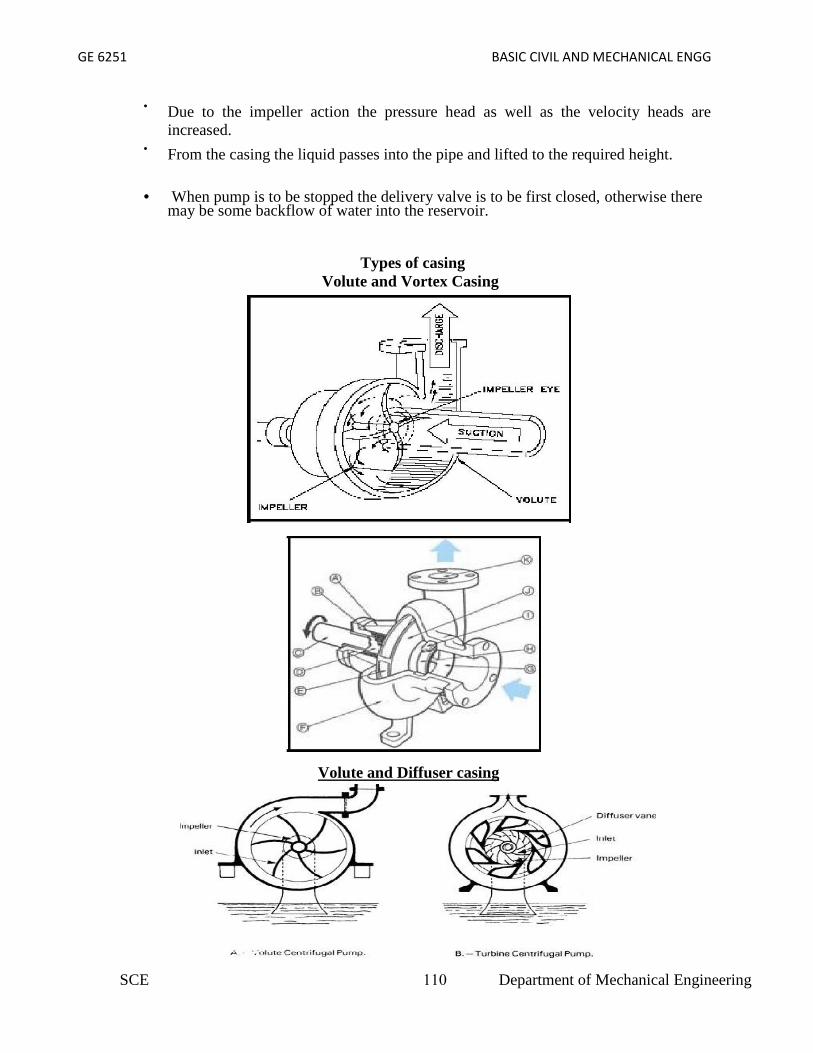
GE 6251 BASIC CIVIL AND MECHANICAL ENGG
Due to the impeller action the pressure head as well as the velocity heads areincreased.
From the casing the liquid passes into the pipe and lifted to the required height.
When pump is to be stopped the delivery valve is to be first closed, otherwise theremay be some backflow of water into the reservoir.
Types of casingVolute and Vortex Casing
Volute and Diffuser casing
SCE 110 Department of Mechanical Engineering

GE 6251 BASIC CIVIL AND MECHANICAL ENGG
Volute Casing: In this type of casing the area of flow gradually increases from the impelleroutlet to the delivery pipe.
Vortex Casing:If a circular chamber is provided between the impeller and volute chamber the casing isknown as Vortex Chamber.
Diffuser C : The impeller is surrounded by a diffuser.
The guide vanes are designed in such a way that the water from the impeller entersthe guide vanes without shock.
It reduces the vibration of the pump.
Diffuser casing, the diffuser and the outer casing are stationery parts.
Priming of a centrifugal Pump: The operation of filling the suction pipe, casing and a portion of delivery pipe with the
liquid to be raised, before starting the pump is known as Priming It is done to remove any air, gas or vapour from these parts of pump.
If a Centrifugal pump is not primed before starting air pockets inside impeller may giverise to vortices and causes discontinuity of flow
Losses in Centrifugal pump:Hydraulic Losses:
Shock or eddy losses at the entrance to and exit from the impeller Losses due to friction in the impeller
Friction and eddy losses in the guide vanes/diffuser and casing
Mechanical Losses: Losses due to disc friction between the impeller and the liquid which fills the
clearance spaces between the impeller and casing Losses pertaining to friction of the main bearing and glands.
Specific speed of Centrifugal Pump:• It is the speed in revolutions per minute at which a geometrically similar impeller would
deliver one cubic meter of liquid per second against a delivery head of one meter.
SCE 111 Department of Mechanical Engineering

GE 6251 BASIC CIVIL AND MECHANICAL ENGG
SCE 24 Department of Mechanical Engineering
3.11 IMPULSE TURBINE:• The steam coming out at a very high velocity through the nozzle impinges on the blades
fixed on the periphery of rotor.
• The blades change the direction of steam flow without change in pressure.
• The resulting force causes the rotation of the turbine.
E.g Pelton wheel.
3.12 REACTION TURBINE:• The high pressure steam from the boiler is passed through the nozzles.
• When the steam comes out through these nozzles, the velocity of steam increasesrelative to the rotating disc.
3.12.1 COMPARISION BETWEEN IMPULSE AND REACTION TURBINE:
S.No. Impulse Turbine Reaction Turbine
1 It consists of nozzles and moving bladesIt consists of fixed blades which actas nozzles and moving blades
2
Steam is expanded completely in thenozzle. All the pressure energy isconverted into kinetic energy
Steam is partially expanded in thefixed blades. Some amount ofpressure energy is converted intokinetic energy
3Pressure of steam is constant over themoving blades.
Pressure drop takes place in themoving blades.
4.
Because of high pressure drop in thenozzles, blade speed and steam speed arehigh.
Because of small pressure drop, bladespeed and steam speed are less.
5. Low Efficiency High Efficiency
6. Occupies less space per unit power Occupies more space per unit power.
GE 6251 BASIC CIVIL AND MECHANICAL ENGG
3.11 IMPULSE TURBINE:• The steam coming out at a very high velocity through the nozzle impinges on the blades
fixed on the periphery of rotor.
• The blades change the direction of steam flow without change in pressure.
• The resulting force causes the rotation of the turbine.
E.g Pelton wheel.
3.12 REACTION TURBINE:• The high pressure steam from the boiler is passed through the nozzles.
• When the steam comes out through these nozzles, the velocity of steam increasesrelative to the rotating disc.
3.12.1 COMPARISION BETWEEN IMPULSE AND REACTION TURBINE:
S.No. Impulse Turbine Reaction Turbine
1 It consists of nozzles and moving bladesIt consists of fixed blades which actas nozzles and moving blades
2
Steam is expanded completely in thenozzle. All the pressure energy isconverted into kinetic energy
Steam is partially expanded in thefixed blades. Some amount ofpressure energy is converted intokinetic energy
3Pressure of steam is constant over themoving blades.
Pressure drop takes place in themoving blades.
4.
Because of high pressure drop in thenozzles, blade speed and steam speed arehigh.
Because of small pressure drop, bladespeed and steam speed are less.
5. Low Efficiency High Efficiency
6. Occupies less space per unit power Occupies more space per unit power.
SCE 112 Department of Mechanical Engineering

GE 6251 BASIC CIVIL & MECHANICAL ENGG
Unit 4
INTERNAL COMBUSTION ENGINES
4.1 INTRODUCTION:Heat Engine:
• Heat Engine is a machine which converts heat energy supplied to it into mechanicalwork.
• Heat energy is supplied to the engine by burning the fuel.
4.2 CLASSIFICATION OF HEAT ENGINES:• Internal Combustion Engines (IC Engines)
In IC engines, combustion of fuel takes place inside the engine cylinder.Examples:Diesel Engines, Petrol Engines, Gas engines.
• External Combustion Engines (EC Engines)In EC engines, combustion of fuel takes place outside the working cylinder.Examples:Steam Engines and Steam turbinesIC Engines are classified into,
(1) Cycle of operation (No of Strokes per cycle)• Two Stroke cycle Engines• Four Stroke Cycle Engines2) Thermodynamic Cycle or Method of Heat addition:• Otto Cycle Engines (Combustion at constant volume)• Diesel Cycle Engines (Combustion at constant Pressure)• Semi Diesel Engines (Dual Combustion Engines)(3) Types of Fuel Used :• Petrol Engines• Diesel Engines• Gas Engines(4) Ignition Method :• Spark Ignition (SI)Compression Ignition(CI)(5) Cooling System:• Air cooled Engines• Water Cooled Engines(6) Valves Location :• L head (Side valve) engine• T Head (Side valve) engine• I head (over head valve) engine• F head (over head inlet and side exhaust) engine
4.3 MAIN COMPONENTS OF IC ENGINES:Cylinder Block:• It is the main block of the engine.• It contains cylinders accurately finished to accommodate pistons• The cylinder block houses crank, camshaft, piston and other engine parts.
SCE 113 Department of Mechanical Engineering
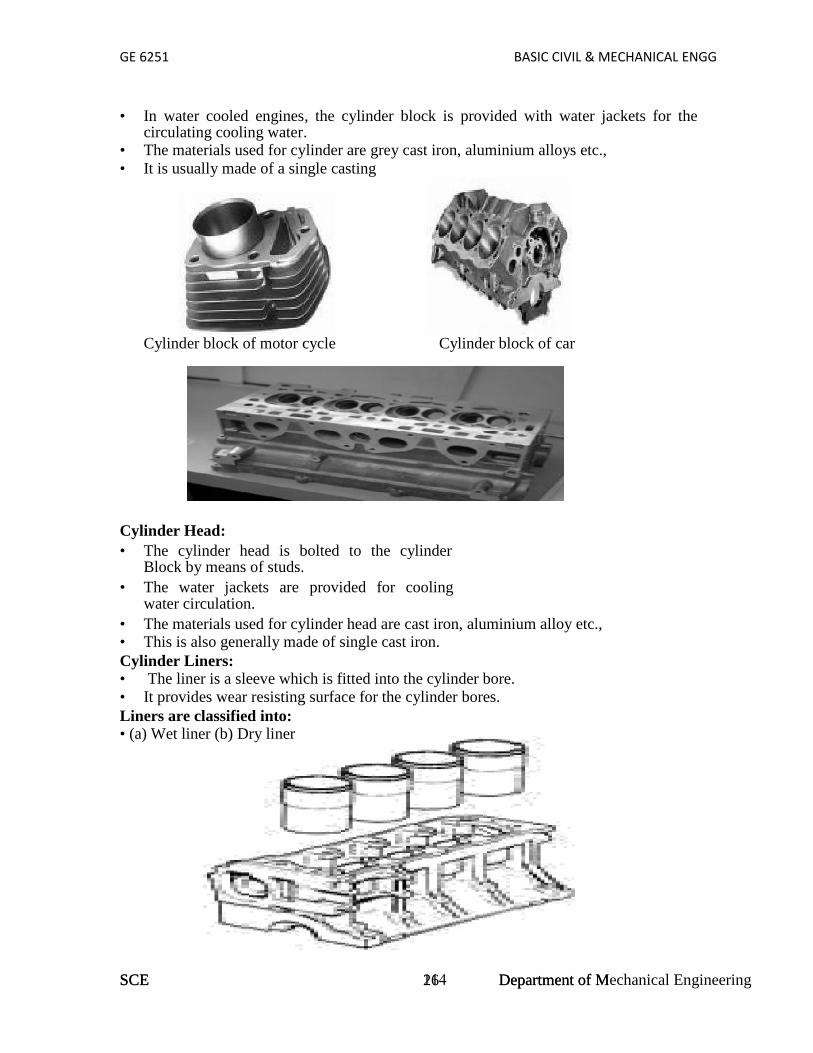
GE 6251 BASIC CIVIL & MECHANICAL ENGG
SCE 26 Department of Mechanical Engineering
• In water cooled engines, the cylinder block is provided with water jackets for thecirculating cooling water.
• The materials used for cylinder are grey cast iron, aluminium alloys etc.,• It is usually made of a single casting
Cylinder block of motor cycle Cylinder block of car
Cylinder Head:• The cylinder head is bolted to the cylinder
Block by means of studs.• The water jackets are provided for cooling
water circulation.• The materials used for cylinder head are cast iron, aluminium alloy etc.,• This is also generally made of single cast iron.Cylinder Liners:• The liner is a sleeve which is fitted into the cylinder bore.• It provides wear resisting surface for the cylinder bores.Liners are classified into:• (a) Wet liner (b) Dry liner
GE 6251 BASIC CIVIL & MECHANICAL ENGG
• In water cooled engines, the cylinder block is provided with water jackets for thecirculating cooling water.
• The materials used for cylinder are grey cast iron, aluminium alloys etc.,• It is usually made of a single casting
Cylinder block of motor cycle Cylinder block of car
Cylinder Head:• The cylinder head is bolted to the cylinder
Block by means of studs.• The water jackets are provided for cooling
water circulation.• The materials used for cylinder head are cast iron, aluminium alloy etc.,• This is also generally made of single cast iron.Cylinder Liners:• The liner is a sleeve which is fitted into the cylinder bore.• It provides wear resisting surface for the cylinder bores.Liners are classified into:• (a) Wet liner (b) Dry liner
SCE 114 Department of Mechanical Engineering

GE 6251 BASIC CIVIL & MECHANICAL ENGG
Cylinder LinersWet Liner : These liners are surrounded or wetted by cooling water. It provides wearresisting surface for the piston to reciprocate. Also it acts as a seal for the water jacket
Dry Liner :Dry liners have metal to metal contact with the cylinder block. They are notdirectly in touch with the cooling water.
Liner Materials:• Liner material should withstand abrasive wear and corrosive.Chromium plated mild teel• tubes are used as liners.
Crankcase : It may be cast integral with the cylinderblock.Some times, it is cast separately and then attached to the block. These materials areused for crank case are cast iron, aluminium alloys or alloy steels.
Oil pan or oil sump:Oil sump is the bottom part of the engine.It contains lubricating oil.A drain plug is provided
the oil sump to drain out the oil.It is made of the pressed sheet.
Piston :The piston serves the following purposes
• It acts as a movable gas tight seal to keep the gases inside the cylinder• It transmits the force of explosionin the cylinder to the
crankshaft through the connecting rod.• Some of the materials used for piston are cast iron, aluminium alloy,
chrome nickel alloy, nickel iron alloy and cast steel.
SCE 115 Department of Mechanical Engineering

GE 6251 BASIC CIVIL & MECHANICAL ENGG
SCE 28 Department of Mechanical Engineering
Piston rings :Piston rings are inserted in the grooves provided in the piston. Two types of piston rings areused in the piston.
1. Compression rings2. Oil rings or oil control rings
4.4 MAIN COMPONENTS OF IC ENGINEPiston Rings (Compression and Oil rings)
GE 6251 BASIC CIVIL & MECHANICAL ENGG
Piston rings :Piston rings are inserted in the grooves provided in the piston. Two types of piston rings areused in the piston.
1. Compression rings2. Oil rings or oil control rings
4.4 MAIN COMPONENTS OF IC ENGINEPiston Rings (Compression and Oil rings)
SCE 116 Department of Mechanical Engineering
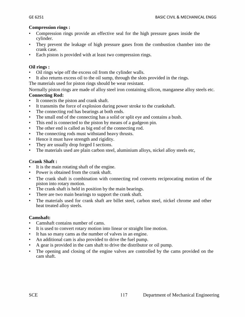
GE 6251 BASIC CIVIL & MECHANICAL ENGG
Compression rings :• Compression rings provide an effective seal for the high pressure gases inside the
cylinder.• They prevent the leakage of high pressure gases from the combustion chamber into the
crank case.• Each piston is provided with at least two compression rings.
Oil rings :• Oil rings wipe off the excess oil from the cylinder walls.• It also returns excess oil to the oil sump, through the slots provided in the rings.The materials used for piston rings should be wear resistant.Normally piston rings are made of alloy steel iron containing silicon, manganese alloy steels etc.Connecting Rod:• It connects the piston and crank shaft.• It transmits the force of explosion during power stroke to the crankshaft.• The connecting rod has bearings at both ends.• The small end of the connecting has a solid or split eye and contains a bush.• This end is connected to the piston by means of a gudgeon pin.• The other end is called as big end of the connecting rod.• The connecting rods must withstand heavy thrusts.• Hence it must have strength and rigidity.• They are usually drop forged I sections.• The materials used are plain carbon steel, aluminium alloys, nickel alloy steels etc,
Crank Shaft :• It is the main rotating shaft of the engine.• Power is obtained from the crank shaft.• The crank shaft is combination with connecting rod converts reciprocating motion of the
piston into rotary motion.• The crank shaft is held in position by the main bearings.• There are two main bearings to support the crank shaft.• The materials used for crank shaft are billet steel, carbon steel, nickel chrome and other
heat treated alloy steels.
Camshaft:• Camshaft contains number of cams.• It is used to convert rotary motion into linear or straight line motion.• It has so many cams as the number of valves in an engine.• An additional cam is also provided to drive the fuel pump.• A gear is provided in the cam shaft to drive the distributor or oil pump.• The opening and closing of the engine valves are controlled by the cams provided on the
cam shaft.
SCE 117 Department of Mechanical Engineering

GE 6251 BASIC CIVIL & MECHANICAL ENGG
4.5 PETROL ENGINESClassification of Petrol Engines
• Two Stroke cycle Petrol Engines
• Four Stroke cycle petrol Engines
4.5.1 TWO STROKE CYCLE PETROL ENGINES:
Two Stroke Cycle Petrol Engine - ConstructionConstruction :
• A piston reciprocates inside the cylinder• It is connected to the crankshaft by means of connecting rod and crank• There are no valves in two stroke engines, instead of valves ports are cut on the
cylinder walls.• There are three ports, namely inlet, exhaust and transfer ports.• The closing and opening of the ports are obtained by the movement of piston. The
crown of piston is made in to a shape to perform this.• A spark plug is also provided.
First Stroke : (Compression, ignition and inductance) (Upward stroke of piston)(a) compression:• The piston moves up from Bottom Dead Centre (BDC) to Top Dead Centre (TDC)• Both transfer and exhaust ports are covered by the piston.• Air fuel mixture which is transferred already into the engine cylinder is compressed
by moving piston.• The pressure and temperature increases at the end of compression.
SCE 118 Department of Mechanical Engineering

GE 6251 BASIC CIVIL & MECHANICAL ENGG
First Stroke : (Compression, ignition and inductance) (Upward stroke of piston)(b) Ignition and Inductance:
• Piston almost reaches the top dead centre• The air fuel mixture inside the cylinder is ignited by means of an electric spark• produced by a spark plug• At the same time, the inlet port is uncovered by the plane.• Fresh air fuel mixture enters the crankcase through the inlet port.
Second Stroke: (Downward Stroke of the engine) :(c)Expansion and Crankcase compression
• The burning gases expand in the cylinder• The burning gases force the piston to move down. Thus useful work is obtained.• When the piston moves down, the air fuel mixture in the crankcase is
partially compressed. This compression is known as Crank casecompression.
Second Stroke: (Downward Stroke of the engine) :(d) Exhaust and transfer:
• At the end of expansion, exhaust port is uncovered.• Burnt gases escape to the atmosphere.• Transfer port is also opened. The partially compressed air fuel mixture enters the
cylinder through the transfer port.• The crown of the piston is made of a deflected shape. So the fresh charge entering the
cylinder is deflected upwards in the cylinder.• Thus the escape of fresh charge along with the exhaust gases is reduced.
4.5.2 TWO STROKE CYCLE DIESEL ENGINES- CONSTRUCTION
Construction :• Two stroke cycle diesel engines require air supply• This air is used to blow out the exhaust gases and to fill the cylinder with clean air• This air is supplied by a blower or air compressor which is driven by engine itself.• These engines may be valve or port type.• A plate is provided in the crank case to admit air into the crank case.• Transfer and exhaust ports are provided in the cylinder.• These ports are covered and uncovered by the moving piston.
First Stroke (Upward Stroke of the piston)(a) Compression and inductance:• The piston moves upwards from Bottom Dead Centre (BDC) to Top Dead Centre (TDC).• Both transfer and exhaust ports are covered.• Air which is transferred already into the engine cylinder is compressed by moving piston.• The pressure and temperature of the air increases.• At the same time, fresh air is admitted into the crankcase through the plate valve (reed
valve)
SCE 119 Department of Mechanical Engineering

GE 6251 BASIC CIVIL & MECHANICAL ENGG
First Stroke (Upward Stroke of the piston)(b) Ignition and inductance.• Piston almost reaches the top dead centre.• The fuel is injected into the hot compressed air inside the cylinder. The fuel mixed with
hot air and burns.• The admission of fresh air into the crankcase continues till the piston reaches the top
centre.
Second Stroke (Downward Stroke of the piston)(c) Expansion and crank case compression:• The burning gases expand in the cylinder.• Burning gases force the piston to move down. Thus useful work is obtained.• At the same time, the air in the crank case is compressed by the movement of piston.• All the ports and the plate valve are in closed position
Second Stroke (Downward Stroke of the piston)(d) Exhaust and Transfer:• At the end of expansion, the exhaust port is uncovered.• The burnt escape to the atmosphere through the exhaust port.• Transfer port is also uncovered shortly after the exhaust port is opened.• The partially compressed air from crank case enters the cylinder the transfer port.• This air is deflected upwards by the deflected shape of the piston.• Thus the entering air helps in forcing out the combustion products from the cylinder• The plate valve remains during this period.
4.5.3 FOUR STROKE CYCLE PETROL ENGINES
Construction :• A piston reciprocates inside the cylinder• The piston is connected to the crank shaftby means of a connecting rod and crank.• The inlet and exhaust valves are Mounted on the cylinder head.• A spark is provided on the cylinderHead.• The fuel used is petrol
SCE 120 Department of Mechanical Engineering

GE 6251 BASIC CIVIL & MECHANICAL ENGG
Four Stroke Petrol Engine- Working
(a) Suction Stroke (First Stroke of the Engine)• Piston moves down from TDC to BDC• Inlet valve is opened and the exhaust valve is closed.• Pressure inside the cylinder is reduced below the atmospheric pressure.• The mixture of air fuel is sucked into the cylinder through the inlet valve.
(b) Compression Stroke : (Second Stroke of the piston)• Piston moves up from BDC to TDC• Both inlet and exhaust valves are closed.• The air fuel mixture in the cylinder is compressed.
(c) Working or Power or Expansion Stroke: (Third Stroke of the Engine)• The burning gases expand rapidly. They exert an impulse (thrust or force) on the
piston. The piston is pushed from TDC to BDC• This movement of the piston is converted into rotary motion of the crankshaft
through connecting rod.• Both inlet and exhaust valves are closed.
(d) Exhaust Stroke (Fourth stroke of the piston)• Piston moves upward from BDC• Exhaust valve is opened and the inlet valve is closed.• The burnt gases are forced out to the atmosphere through the exhaust valve (Some of
the burnt gases stay in the clearance volume of the cylinder)• The exhaust valve closes shortly after TDC• The inlet valve opens slightly before TDC and the cylinder is ready to receive
fresh charge to start a new cycle.
Summary :• Compression ratio varies from 5 to 8• The pressure at the end of compression is about 6 to 12 bar.• The temperature at the end of the compression reaches 250o C to 350o C
SCE 121 Department of Mechanical Engineering
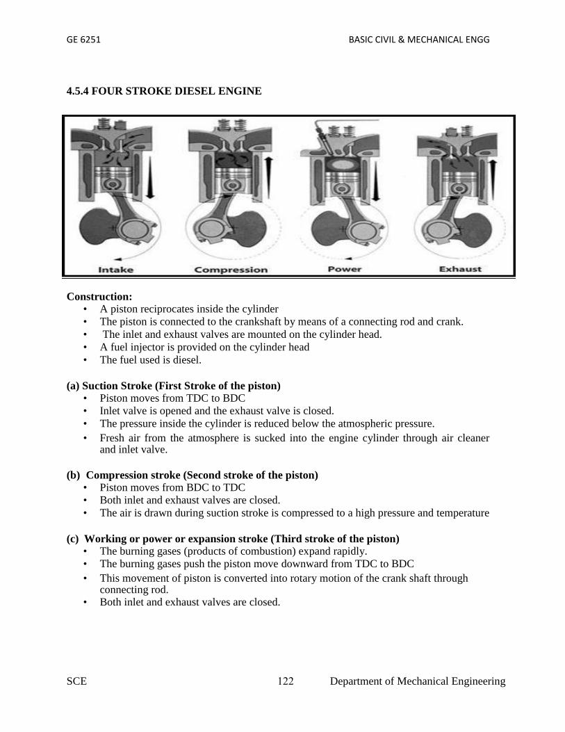
GE 6251 BASIC CIVIL & MECHANICAL ENGG
4.5.4 FOUR STROKE DIESEL ENGINE
Construction:• A piston reciprocates inside the cylinder• The piston is connected to the crankshaft by means of a connecting rod and crank.• The inlet and exhaust valves are mounted on the cylinder head.• A fuel injector is provided on the cylinder head• The fuel used is diesel.
(a) Suction Stroke (First Stroke of the piston)• Piston moves from TDC to BDC• Inlet valve is opened and the exhaust valve is closed.• The pressure inside the cylinder is reduced below the atmospheric pressure.• Fresh air from the atmosphere is sucked into the engine cylinder through air cleaner
and inlet valve.
(b) Compression stroke (Second stroke of the piston)• Piston moves from BDC to TDC• Both inlet and exhaust valves are closed.• The air is drawn during suction stroke is compressed to a high pressure and temperature
(c) Working or power or expansion stroke (Third stroke of the piston)• The burning gases (products of combustion) expand rapidly.• The burning gases push the piston move downward from TDC to BDC• This movement of piston is converted into rotary motion of the crank shaft through
connecting rod.• Both inlet and exhaust valves are closed.
SCE 122 Department of Mechanical Engineering

GE 6251 BASIC CIVIL & MECHANICAL ENGG
(d) Exhaust Stroke (Fourth stroke of the piston)• Piston moves from BDC to TDC• Exhaust valve is opened the inlet valve is closed.• The burnt gases are forced out to the atmosphere through the exhaust valve. (some of the
burnt gases stay in the clearance volume of the cylinder)• The exhaust valve closes shortly after TDC• The inlet valve opens slightly before TDC and the cylinder is ready to receive fresh air
to start a new cycle.
4.6 SCAVENGING• It is the process of forcing out the burnt exhaust gases from the cylinder for admitting
the fresh charge into the cylinder.• This action takes place in the two stroke cylinder.
4.6.1 SCAVENGING PROCESS• The charge (air fuel mixture or air) enters the engine cylinder from the crank case at a
pressure higher than the exhaust gases.• This fresh charge forces the exhaust gases to the atmosphere through the exhaust
port.• During the period both the transfer and exhaust ports are kept open for a short
period.• Hence there is a possibility of the fresh charge escaping out with the burnt gases.• This is over come by designing the piston to have a deflected shape.• This shape of piston deflects the fresh charge upward in the engine cylinder.• It also helps out in forcing out the exhaust gases to atmosphere.• This process is known as Scavenging.
4.7 COMPARISON BETWEEN SI AND CI ENGINES (GENERAL COMPARISON):
S.NO. Spark Ignition Engines (SI) Compression Ignition Engines (CI)
1 It draws air fuel mixture into the cylinderduring suction stroke
It draws only air into the cylinder during suctionstroke.
2 Petrol engines operate with low pressureand temperature
Diesel engines operate with high pressure andtemperature
3. Pressure ranges from 6 to 12 barTemperature ranges from 250oC to 300oC
Pressure ranges from 35 to 40 bar Temperatureranges from 600oC to 700oC
4 It is fitted with carburettor and spark plugs It is fitted with fuel injection pump and injectors
5 The burning of fuel takes place at constantvolume
The burning of fuel takes place at constantpressure
6. Ignition of air fuel mixture takes place byan electric spark produced by spark plug
Ignition of air fuel takes placed by a injection offuel into the hot compressed air.
7 Petrol engines are quality governedengines. The speed of petrol engines arecontrolled by varying the quantity of airfuel mixture.
Diesel engines are quantity governed engines.The speed of diesel engines is controlled byvarying quality of air fuel mixture. (rich or weakmixture)
8 Petrol engines are widely used inautomobiles and aeroplanes etc.,
Diesel engines are widely used in heavyvehicles, such as buses, lorries, trucks etc.,
SCE 123 Department of Mechanical Engineering

GE 6251 BASIC CIVIL & MECHANICAL ENGG
4.8 COMPARISON BETWEEN SI AND CI ENGINES (MERITS AND DEMERITS):
S.No. Spark Ignition Engines (SI) Compression Ignition Engines (CI)
1
Merits: Otto cycle is employed inpetrol engine. Otto cycle is moreefficient for a given compressionratio.
Demerits: Diesel engines works on dieselcycle. Diesel cycle is less efficient thanOtto cycle for a given compression ratio.
2Operating speed is more. Speed rangeis 3000 to 6000 rpm
Operating speed is less. Speed range is400to 3500 rpm.
3Starting is easy, since cranking effortrequired is less
Starting is difficult since more crankingeffort is required.
4Merits: Initial cost and maintenancecost are less
Demerits: More initial and maintenancecosts since the construction is heavy andsturdy.
5 Produces less noise. Produces more noise.
6 Weight per unit power is less Weight per unit power is more.
7 Specific fuel consumption is more. Specific fuel consumption is less
8The fuel used is petrol. It is costlierthan diesel. It is volatile and firehazard is more
The fuel used is diesel. It is cheaper thanpetrol. It is less volatile and fire hazard isless.
4.9 COMPARISON BETWEEN FOUR STROKE CYCLE AND TWO STROKE CYCLEENGINE (MERITS AND DEMERITS):
S.No. Two Stroke Cycle Engine Four Stroke Cycle Engine
1Merits: One power stroke in onerevolution of the crankshaft
Demerits: One power stroke in tworevolutions of the crank shaft
2Power developed for the same enginespeed theoretically twice that of a fourstroke engine
Power developed for the same enginespeed is theoretically half that of twostroke engine.
3Simple design and lighter in constructionfor the same power
For the same power complicated designand heavier in construction
4Merits: Uniform torque is obtained. Hencea lighter fly wheel can be used
Demerits: Non uniform torque on thecrankshaft. Hence a heavier flywheel isrequired for balancing.
5Design of ports is simpler. Hence initialcost is less
Design valve mechanism is difficult.Hence initial cost is more.
6Mechanical efficiency is high. No movingparts like cam, follower, rocker arm valvesetc.,
Mechanical efficiency is less. Power islost due to friction caused by valvemechanism
7 Merits: Starting is easy Demerits: Starting is not so easy
8 These engines are generally air cooled These engines are generally water cooled.
SCE 124 Department of Mechanical Engineering

GE 6251 BASIC CIVIL & MECHANICAL ENGG
4.10 COMPARISON BETWEEN FOUR STROKE CYCLE AND TWOSTROKE CYCLE ENGINE (MERITS AND DEMERITS):
4.11 I.C ENGINE TERMINOLGOGYThe standard terms used in I.C Engines are1. Bore:
Inside diameter of the cylinder is termed as Bore.2. Top Dead Center (TDC):
The extreme position reached by the piston at the top of the cylinder inthe vertical engine is called Top Dead center.3. Bottom Dead Center (BDC):
The extreme position reached by the piston at the Bottom of the cylinderin the vertical engine is called Bottom Dead center.4. Stroke:
The nominal distance travelled by the piston in the cylinder betweenthe extreme upper and lower positions of the piston (TDC &BDC) is termed asstroke.5. Compression ratio (r):
It is the ratio of Maximum cylinder volume to the Clearance volume.6. Cylinder volume (v):
It is the sum of swept volume and the Clearance volume.V = Vs + Vc
7. Swept volume (Vs):It is the volume of space generated by the movement of piston
S.No. Two Stroke Cycle Engine Four Stroke Cycle Engine
1DeMerits: Consumption of lubricatingoil is more, because less time is availableto remove the heat
Merits: Consumption of lubricating oil isless, because more time is allowed forremoving heat from the cylinder.
2 More wear and tear of moving parts. Less wear and tear of parts is less
3Some of the fresh air fuel mixture mayescape with exhaust gases. Hence fuelconsumption is more
Fuel cannot escape with exhaust gases.Hence fuel consumption is less.
4 DeMerits: Thermal efficiency is less. Merits: Thermal efficiency is more.
5It produces more noise due to suddenrelease of exhaust gases
Noise is less is less. Exhaust gases arereleased in separate stroke.
6Scavenging is poor, since exhaust port isopen only for a short time
Scavenging is better, since there is aseparate exhaust stroke for the removal ofexhaust gases
7
Merits: Poor scavenging leads to mixingof fresh charge with exhaust gases. Thisresults in poor performance, slowrunning
Demerits: Better performance andefficiency is more
8Used in light vehicles, like bikes,scooters, mopeds, etc.,
Used in heavy vehicles, like buses, lorries,trucks etc.,
SCE 125 Department of Mechanical Engineering
GE 6251 BASIC CIVIL & MECHANICAL ENGG
from one dead center to another dead center.8.Clearance Volume( Vc):
It is the space in the cylinder, when the piston is at Top DeadCenter
4.11.1 MAJOR PARTS OF AN IC ENGINE
1. Cylinder• It is a round cylindrical casting in which a piston slides in and out to make
strokes.• Combustion take place inside the cylinder. The cylinder is closed by a cylinder
head.Material: Grey cast iron, Aluminium
2. Cylinder headIt is fitted to the top of the cylinder. It has inlet and outlet values, spark plug, Fuel
injector, Water jackets.Material: C.I, Aluminium
3. PistonIt is a device which transmits the energy (or) force of the expanding gas to the
connecting rod. It slides up and down inside the cylinder.Material: C.I, Aluminium alloy, Cast steel
4. Piston ringsPiston rings are inserted in the grooves of piston. There are two
types of rings.1) Oil ring ( One ring is used)2) Compression ring( Two ring is used)
5. Connecting rodIt converts the reciprocating motion of the piston into rotary motion of
crankshaft. The small end of the connecting rod is connected to piston and thebig end is connected to the crankshaft.Material: Plain carbon steel, Aluminium alloys6. Crank shaft
It is the device used for getting power from the motion of thepiston and connecting rod and this power is applied to the flywheel.
Material: Alloys steel.7. Camshaft
It operates the opening and closing of the engine values. It has numberof cams which are driven by crank shaft through timing gears. The function of the camis to convert the rotary motion into the linear reciprocating motion
Material: Alloys steel8. Crank case
It is the bottom portion of the I.C engine and holds the cylinder andthe crank case. It also serves as a pump for the lubricating oil.
Material: Aluminium alloy, Cast iron9. Flywheel:
It is a big wheel attached with crankshaft. It maintains the speed of theengine.
10. Valves: The function of the value is to admit the fresh charge in the cylinder and tosend the exhaust gases out. There are two values namely inlet value and outlet value.
SCE 126 Department of Mechanical Engineering

GE 6251 BASIC CIVIL & MECHANICAL ENGG
Material: Inlet value: Nickel chrome.Outlet value: Nickel chrome, Stainless steel etc
11. Water JacketsWater jackets are provided in the cylinder head. The purpose of
water jackets is to keep the walls of the engine cool.
4.12 STEAM BOILERS• Generates steam by transferring heat by burning of fuel to water.
• Energy released by burning fuel (solid, liquid or gaseous) is transferred to thewater in the boiler.
Classification of boilers:The steam boilers are classified as
• According to flow of water and hot gases.1. Fire Tube Boilers2. Water Tube Boilers• According to the method of firing.1. Internally fired boilers2. Externally fired boilers• According to the Pressure developed1. Low pressure boilers2. High pressure boilers
In fire tube boilers,• The hot gases pass through the tubes surrounded by water.• The water is get heated up and converted into steam• The exhaust gases are sent to atmosphere through chimney.
E.g Locomotive boiler, Lancashire boiler.
4.12.1 FIRE TUBE & WATER TUBE BOILERS
According to flow of water and hot gases:In water tube boilers,
• Water is circulated through number of tubes and the hot flue gases flow overthese tubes.
• A number of tubes are connected with boiler drum through headers.
SCE 127 Department of Mechanical Engineering

GE 6251 BASIC CIVIL & MECHANICAL ENGG
• The hot gases flow over these tubes many times before escaping through thestack.
• The water is converted into steam and steam occupies steam space.E.g. Babcock & Wilcox, stirling, BHEL boiler, Velox, Lamont, Lo-effler boilers.According to the method of firing:In internally fired boilers, the furnace grate is provided inside the boiler shell.(E.gLancashire, Locomotive boilers) In externally fired boilers,
• The furnace grate is provided outside or built under the boiler shell.4.12.2 INTERNALLY FIRED BOILER:
SCE 128 Department of Mechanical Engineering
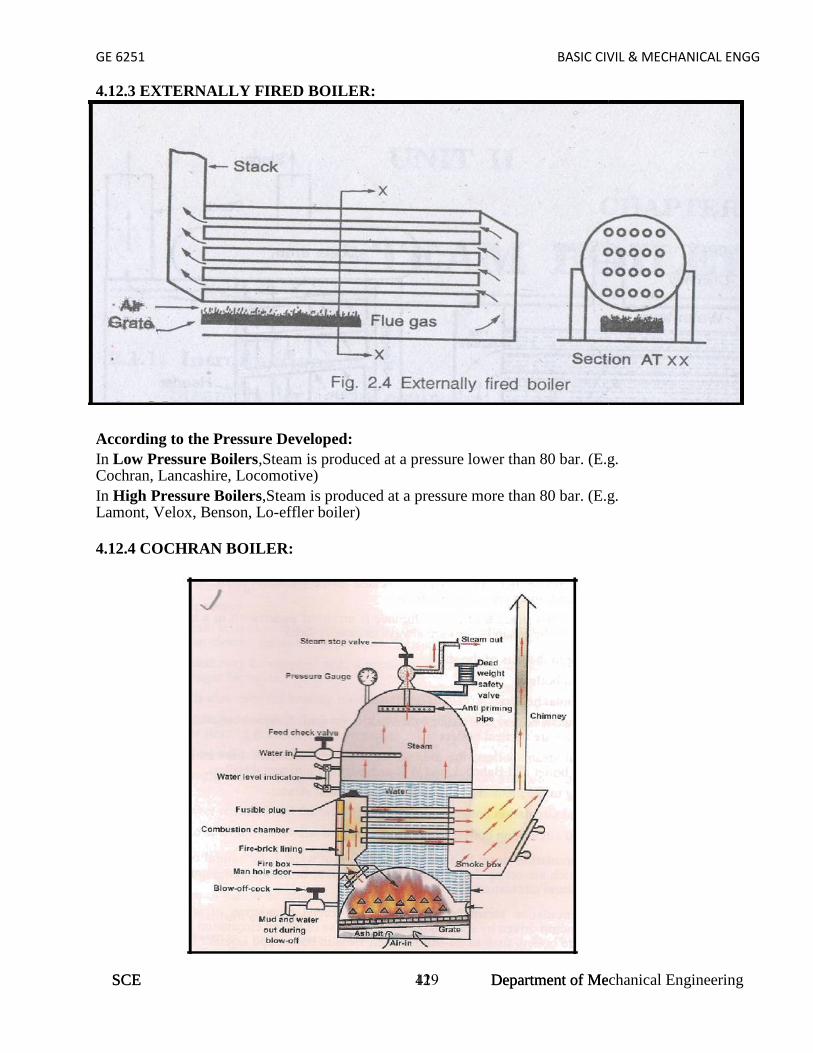
GE 6251 BASIC CIVIL & MECHANICAL ENGG
SCE 41 Department of Mechanical Engineering
4.12.3 EXTERNALLY FIRED BOILER:
According to the Pressure Developed:In Low Pressure Boilers,Steam is produced at a pressure lower than 80 bar. (E.g.Cochran, Lancashire, Locomotive)In High Pressure Boilers,Steam is produced at a pressure more than 80 bar. (E.g.Lamont, Velox, Benson, Lo-effler boiler)
4.12.4 COCHRAN BOILER:
GE 6251 BASIC CIVIL & MECHANICAL ENGG
4.12.3 EXTERNALLY FIRED BOILER:
According to the Pressure Developed:In Low Pressure Boilers,Steam is produced at a pressure lower than 80 bar. (E.g.Cochran, Lancashire, Locomotive)In High Pressure Boilers,Steam is produced at a pressure more than 80 bar. (E.g.Lamont, Velox, Benson, Lo-effler boiler)
4.12.4 COCHRAN BOILER:
SCE 129 Department of Mechanical Engineering

GE 6251 BASIC CIVIL & MECHANICAL ENGG
SCE 42 Department of Mechanical Engineering
Coal is fed into the grate through the fire hole and burnt.• Ash formed during the burning is collected in the ash pit provided just below the grate.• Ash is then removed manually.• The hot gases from the grate pass through the combustion chamber to the horizontal fire
tubes and transfer the heat by convection.• The flue gases coming out of fire tubes pass through the smoke box and escape to the
atmosphere through the chimney.• Smoke box is provided with a door for cleaning the fire tubes and smoke box.• The working pressure and steam capacity of cochran boiler are 6.5 bar and 3500 kg /hr
respectively.4.12.5 LAMONT BOILER:
• It is a water tube, forced circulation and externally fired high pressure boiler.• The capacity of the plant is 50 tonnes/hr• Pressure of the steam generated is 170 bar.• Temperature of the steam produced is 500o C
Working:• Feed water is pumped to the boiler by the feed pump through the economiser.• Economiser preheats the feed water by using hot gases leaving the boiler.• The circulating pump circulates the water from the drum under high pressure to prevent the
tubes from being overheated• Water is evaporated into steam when passing through these tubes.• The water and steam from the tube enters the boiler drum where the steam is separator.• This steam is passed through a convection superheater and the steam is superheated by the
flue gases.
GE 6251 BASIC CIVIL & MECHANICAL ENGG
Coal is fed into the grate through the fire hole and burnt.• Ash formed during the burning is collected in the ash pit provided just below the grate.• Ash is then removed manually.• The hot gases from the grate pass through the combustion chamber to the horizontal fire
tubes and transfer the heat by convection.• The flue gases coming out of fire tubes pass through the smoke box and escape to the
atmosphere through the chimney.• Smoke box is provided with a door for cleaning the fire tubes and smoke box.• The working pressure and steam capacity of cochran boiler are 6.5 bar and 3500 kg /hr
respectively.4.12.5 LAMONT BOILER:
• It is a water tube, forced circulation and externally fired high pressure boiler.• The capacity of the plant is 50 tonnes/hr• Pressure of the steam generated is 170 bar.• Temperature of the steam produced is 500o C
Working:• Feed water is pumped to the boiler by the feed pump through the economiser.• Economiser preheats the feed water by using hot gases leaving the boiler.• The circulating pump circulates the water from the drum under high pressure to prevent the
tubes from being overheated• Water is evaporated into steam when passing through these tubes.• The water and steam from the tube enters the boiler drum where the steam is separator.• This steam is passed through a convection superheater and the steam is superheated by the
flue gases.SCE 130 Department of Mechanical Engineering

GE 6251 BASIC CIVIL & MECHANICAL ENGG
• This super heated steam is supplied to the prime mover through steam outlet.• The water level in the drum is kept constant by pumping the feed water into the boiler
drum.• The air is preheated by the flue gases before entering the combustion chamber to aid the
combustion of the fuel.• This type of boiler has a working pressure of 170 bar.• They can produce the steam at the rate of 45000 kg per hour.
4.13 BOILER MOUNTINGS & ACCESSORIES:
Boiler Mountings:• Boiler mountings are primarily intended for the safety of the boiler and for complete
control of steam generation process.Boiler Accessories :
• Boiler accessories are installed to increase the efficiency of the boiler plants to help inproper working of boiler unit.
Boiler Mountings:• Dead weight safety valve.• Spring loaded safety valve• Fusible plug• Pressure gauge
Dead Weight Safety Valve:
Dead Weight Safety Valve:
• Weights are placed sufficiently in the weight carrier.
• The total load on the valve includes the weight of the carrier, the weight of the cover, theweight of the discs and the weight of the valve itself.
• When the steam pressure exceeds the normal limit, the valve along with the weightcarrier is lifted off its seat.
• Thus the steam escapes through the discharge pipe.
SCE 131 Department of Mechanical Engineering

GE 6251 BASIC CIVIL & MECHANICAL ENGG
SCE 44 Department of Mechanical Engineering
Spring Loaded Safety Valve:
• The steam pressure acts below the valves.
• When the steam pressure is normal the valves are held in their seats tightly by the springforce.
• When the steam pressure in the boiler exceeds the working pressure, both valves arelifted off their seats.
• Thus the steam from the boiler escapes the boiler and steam pressure is reduced.
• The blow off pressure is adjusted by loosening or screwing the nut.
Fusible Plug:
• Under normal working conditions, the fusible plug is completely covered with water.• Hence the temperature of the plug is not increased appreciably during combustion
process.• When the water level falls below the safe limit the fusible plug is uncovered from water and
exposed to steam.• The furnace heat over heats the plug and it melts the fusible metal andcopper plug falls down.• Due to this water steam mixture rushes into the furnace and the fire isextinguished.
GE 6251 BASIC CIVIL & MECHANICAL ENGG
Spring Loaded Safety Valve:
• The steam pressure acts below the valves.
• When the steam pressure is normal the valves are held in their seats tightly by the springforce.
• When the steam pressure in the boiler exceeds the working pressure, both valves arelifted off their seats.
• Thus the steam from the boiler escapes the boiler and steam pressure is reduced.
• The blow off pressure is adjusted by loosening or screwing the nut.
Fusible Plug:
• Under normal working conditions, the fusible plug is completely covered with water.• Hence the temperature of the plug is not increased appreciably during combustion
process.• When the water level falls below the safe limit the fusible plug is uncovered from water and
exposed to steam.• The furnace heat over heats the plug and it melts the fusible metal andcopper plug falls down.• Due to this water steam mixture rushes into the furnace and the fire isextinguished.
SCE Department of Mechanical Engineering

GE 6251 BASIC CIVIL & MECHANICAL ENGG
Bourdan Tube Pressure Gauge
• The steam pressure is applied to the• The elliptical cross section of the tube to straighten out slightly.• The closed end of the Bourdon tube moves.• This movement actuates the toothed sector and pinion rotates.• The pointer is mounted on the pinion. Hence the pointer moves on the
graduated dial in clockwise, to indicate the steam pressure.
Water Level Indicator
• To know the water level in the boiler the handles of the steam cock and watercock are kept in vertical positions.
• Water rushes through the bottom casting and steam rushes through the uppercasting to the gauge glass tube.
• The level of water corresponds to the water level in the boiler.
SCE 133 Department of Mechanical Engineering
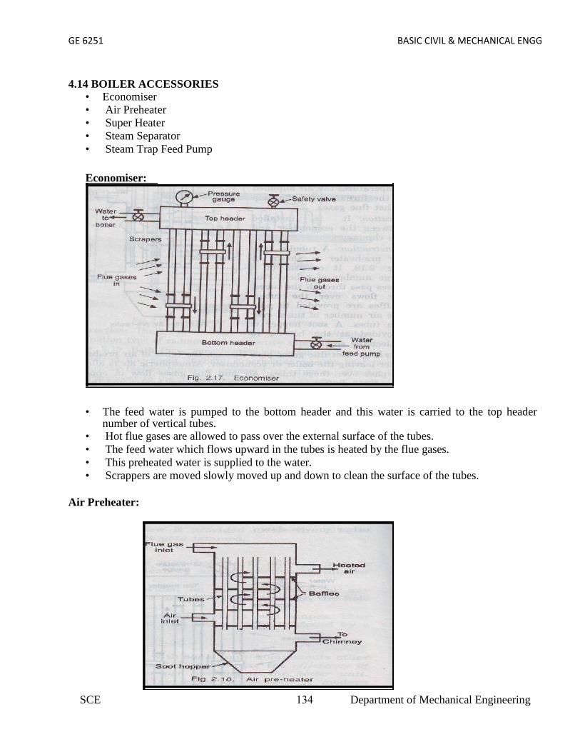
GE 6251 BASIC CIVIL & MECHANICAL ENGG
4.14 BOILER ACCESSORIES• Economiser• Air Preheater• Super Heater• Steam Separator• Steam Trap Feed Pump
Economiser:
• The feed water is pumped to the bottom header and this water is carried to the top headernumber of vertical tubes.
• Hot flue gases are allowed to pass over the external surface of the tubes.• The feed water which flows upward in the tubes is heated by the flue gases.• This preheated water is supplied to the water.• Scrappers are moved slowly moved up and down to clean the surface of the tubes.
Air Preheater:
SCE 134 Department of Mechanical Engineering

GE 6251 BASIC CIVIL & MECHANICAL ENGG
• Hot flue gases pass through the tubes of air preheater after leaving the boiler or economiser.• Air and flue gases flow in opposite directions.• Baffles are provided in the air preheater and the air passes number of times over the tubes.• Heat is absorbed by the air from the flue gases.• This preheated is supplied to the furnace to aid combustion.Super heater
• Steam stop valve is opened.• The steam from the evaporator drum is passed through the super heater tubes.• First the steam passed through the radiant super heater and then to the convective super heater.• The steam is heated when it passes through these super heaters and converted into the super
heated steam.• This superheated steam is supplied to the turbine through the valve.• The steam is allowed into the separator.• The steam strikes the baffle plates and the direction of flow is changed.• As a result, heavier particles in steam falls down to the bottom of the separator.• The separated steam is free from water particles.• It is passed to the turbine or engine through the outlet pipe.
SCE 135 Department of Mechanical Engineering

GE 6251 BASIC CIVIL & MECHANICAL ENGG
Steam Separator
Stream Trap
• The condensed water enters the steam trap by gravity.• When the water level in the trap rises high enough, the ball float is lifted.• This causes the valve to open and the water is discharged through the outlet.• After the discharge of water, the float moves down.• This causes the valve to close again.
SCE 136 Department of Mechanical Engineering

GE 6251 BASIC CIVIL & MECHANICAL ENGG
4.15 DIFFERENCES BETWEEN BOILER MOUNTINGS AND ACCESSORIES:
Sl. No. Boiler Mountings Boiler Accessories
1Mountings are fitted for the safety of theboiler.
Accessories are fitted to increase theefficiency
2 They form integral parts of the boiler They are not integral part of the boiler
3They are usually mounted on the boilershell
They are usually installed outside theboiler shell
4A boiler should not be operated withoutmountings
A boiler can be operated withoutaccessories
SCE 137 Department of Mechanical Engineering

GE 6251 BASIC CIVIL AND MECHANICAL ENGG
UNIT V
REFRIGERATION AND AIRCONDITIONING
5.1 REFRIGERATION: It is defined as the process of providing and maintaining a temperature wellbelow that of surrounding atmosphere. In other words refrigeration is the process of cooling substance.
Refrigerators and heat pumps: If the main purpose of the machine is to cool some object, the machine is named
as refrigerator. If the main purpose of machine is to heat a medium warmer than the
surroundings, the machine is termed as heat pump.
Terminologies of Refrigeration:Refrigerating Effect (N):
It is defined as the quantity of heat extracted from a cold body or spaceto be cooled in a given time.N= Heat extracted from the cold
space Time taken
Specific Heat of water and ice :It is the quantity of heat required to raise or lower the
temperature of one kg of water (or ice), through one kelvin or (10 c) in one second.
Specific heat of water, Cpw = 4.19 kJ/kg KSpecific heat of ice, Cpice = 2.1 kJ/kg K.
Capacity of a Refrigeration Unit : Capacity of a refrigerating machines are expressed by their cooling capacity. The standard unit used for expressing the capacity of refrigerating machine
is ton of refrigeration.
SCE 138 Department of Mechanical Engineering

GE 6251 BASIC CIVIL AND MECHANICAL ENGG
One ton of refrigeration is defined as, “the quantity of heat effect) tofreeze one ton of water Heat extracted from at oo c = latent heat of ice intoone ton of ice in a duration of 24 hours at 0o C”.
Latent heat of ice= 336 kJ/kg i.e., 336 kJ of heat should be extracted one kg of water at0o C to convert it into ice.One ton of refrigeration = 336x1000 kJ/24 hrs.
= 336x1000 kJ/min24x60
One ton of refrigeration = 233.333 kJ/min= 3.8889 kJ/sec
Co efficient of PerformanceIt is defined as the ratio of heat extracted in a given time
(refrigerating effect) to the work input.Co efficient of performance = Heat extracted in evaporator
Work Input
Co efficient of performance = Refrigerating EffectWork Input
Co efficient of performance = NW
The COP is always greater than 1 and known as theoretical coefficient of performance.Applications of Refrigeration:
In chemical industries, for separating and liquefying the gases. In manufacturing and storing ice. For the preservation of perishable food items in cold storages. For cooling water. For controlling humidity of air manufacture and heat treatment of steels. For chilling the oil to remove wax in oil refineries. For the preservation of tablets and medicines in pharmaceutical industries. For the preservation of blood tissues etc., For comfort air conditioning the hospitals, theatres, etc.,
Properties of Refrigeration: A good refrigerant should have high latent heat of vapourisation. It should have low boiling and low freezing point. It should be non toxic and should non corrosiveness It should be non flammable and non explosive. It should have high thermal conductivity It should be easy to handle It should have low specific volume of vapour. It should have high co efficient of performance
SCE 139 Department of Mechanical Engineering

GE 6251 BASIC CIVIL AND MECHANICAL ENGG
SCE 52 Department of Mechanical Engineering
5.2 VAPOUR COMPRESSION REFRIGERATION SYSTEM
Construction:
This system consists of a compressor, condenser, a receiver tank, an expansionvalve and an evaporator.
Compressor : Reciprocating compressors generally used. For very big plantscentrifugal compressors directly coupled with high speed rotating engines (gasturbine) are used.
For very big plantsCentrifugal compressors directly coupled with high speedrotating engines (gas turbine) are used
Condenser : It is a coil of tubes made of copper. Receiver tank: It is the reservoir of liquid refrigerant. Expansion Valve: This is a throttle valve. High pressure refrigerant is made to flow at
a controlled rate through this valve. Evaporator : It is the actual cooler and kept in the space to be cooled. The evaporator
is a coil of tubes made of copper5.3 VAPOUR ABSORPTION REFRIGERATION SYSTEM:Construction: The vapour absorption system consists of a condenser, an expansion valve and an
evaporator. They perform the same as they do in vapour compression method. In addition to these, this system has an absorber, a heat exchanger, an analyser and a
rectifier.Working:
• Dry ammonia vapour at low pressure passes in to the absorber from the evaporator.• In the absorber the dry ammonia vapour is dissolved in cold water and strong
solution of ammonia is formed.• Heat evolved during the absorption of ammonia is removed by circulating cold
water through the coils kept in the absorber.• The highly concentrated ammonia (known as Aqua Ammonia) is then pumped by
a pump to generator through a heat exchanger.
GE 6251 BASIC CIVIL AND MECHANICAL ENGG
5.2 VAPOUR COMPRESSION REFRIGERATION SYSTEM
Construction:
This system consists of a compressor, condenser, a receiver tank, an expansionvalve and an evaporator.
Compressor : Reciprocating compressors generally used. For very big plantscentrifugal compressors directly coupled with high speed rotating engines (gasturbine) are used.
For very big plantsCentrifugal compressors directly coupled with high speedrotating engines (gas turbine) are used
Condenser : It is a coil of tubes made of copper. Receiver tank: It is the reservoir of liquid refrigerant. Expansion Valve: This is a throttle valve. High pressure refrigerant is made to flow at
a controlled rate through this valve. Evaporator : It is the actual cooler and kept in the space to be cooled. The evaporator
is a coil of tubes made of copper5.3 VAPOUR ABSORPTION REFRIGERATION SYSTEM:Construction: The vapour absorption system consists of a condenser, an expansion valve and an
evaporator. They perform the same as they do in vapour compression method. In addition to these, this system has an absorber, a heat exchanger, an analyser and a
rectifier.Working:
• Dry ammonia vapour at low pressure passes in to the absorber from the evaporator.• In the absorber the dry ammonia vapour is dissolved in cold water and strong
solution of ammonia is formed.• Heat evolved during the absorption of ammonia is removed by circulating cold
water through the coils kept in the absorber.• The highly concentrated ammonia (known as Aqua Ammonia) is then pumped by
a pump to generator through a heat exchanger.SCE 52 Department of Mechanical Engineering
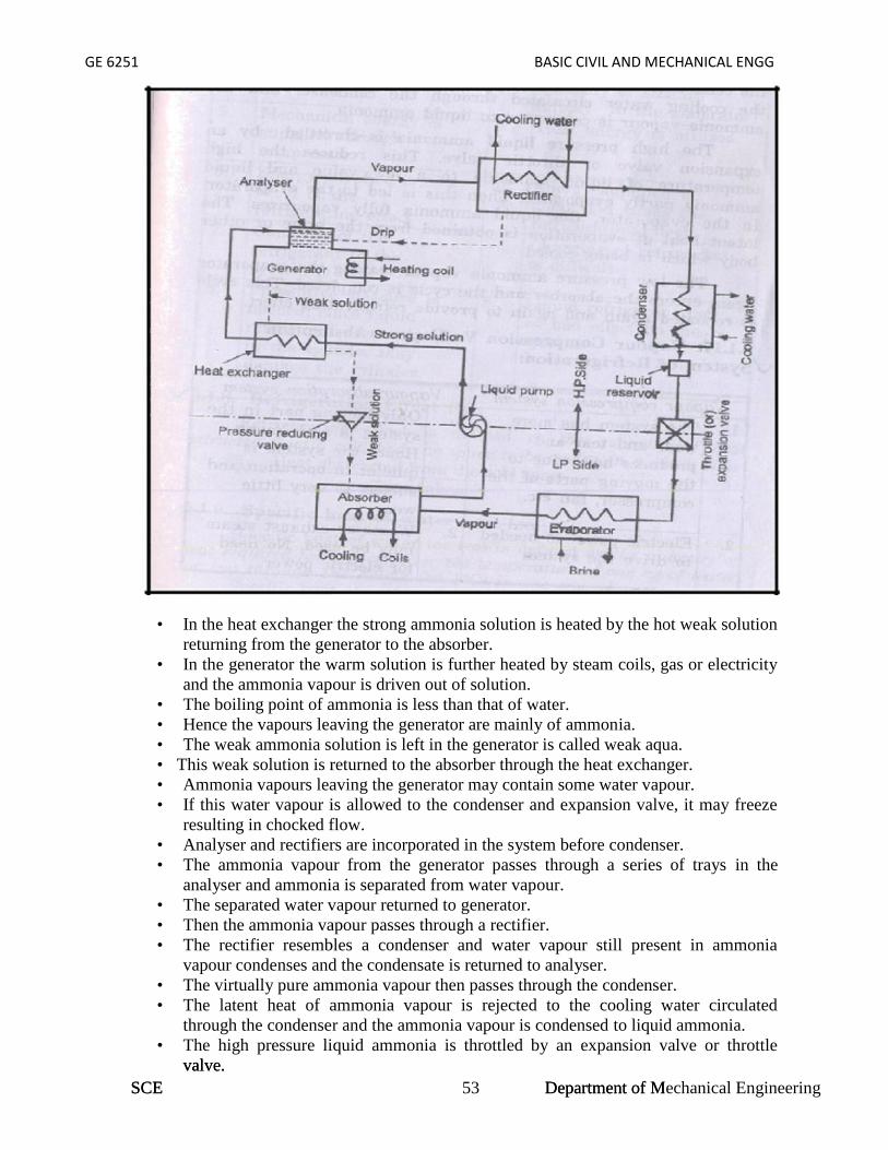
GE 6251 BASIC CIVIL AND MECHANICAL ENGG
SCE 53 Department of Mechanical Engineering
• In the heat exchanger the strong ammonia solution is heated by the hot weak solutionreturning from the generator to the absorber.
• In the generator the warm solution is further heated by steam coils, gas or electricityand the ammonia vapour is driven out of solution.
• The boiling point of ammonia is less than that of water.• Hence the vapours leaving the generator are mainly of ammonia.• The weak ammonia solution is left in the generator is called weak aqua.• This weak solution is returned to the absorber through the heat exchanger.• Ammonia vapours leaving the generator may contain some water vapour.• If this water vapour is allowed to the condenser and expansion valve, it may freeze
resulting in chocked flow.• Analyser and rectifiers are incorporated in the system before condenser.• The ammonia vapour from the generator passes through a series of trays in the
analyser and ammonia is separated from water vapour.• The separated water vapour returned to generator.• Then the ammonia vapour passes through a rectifier.• The rectifier resembles a condenser and water vapour still present in ammonia
vapour condenses and the condensate is returned to analyser.• The virtually pure ammonia vapour then passes through the condenser.• The latent heat of ammonia vapour is rejected to the cooling water circulated
through the condenser and the ammonia vapour is condensed to liquid ammonia.• The high pressure liquid ammonia is throttled by an expansion valve or throttle
valve.
GE 6251 BASIC CIVIL AND MECHANICAL ENGG
• In the heat exchanger the strong ammonia solution is heated by the hot weak solutionreturning from the generator to the absorber.
• In the generator the warm solution is further heated by steam coils, gas or electricityand the ammonia vapour is driven out of solution.
• The boiling point of ammonia is less than that of water.• Hence the vapours leaving the generator are mainly of ammonia.• The weak ammonia solution is left in the generator is called weak aqua.• This weak solution is returned to the absorber through the heat exchanger.• Ammonia vapours leaving the generator may contain some water vapour.• If this water vapour is allowed to the condenser and expansion valve, it may freeze
resulting in chocked flow.• Analyser and rectifiers are incorporated in the system before condenser.• The ammonia vapour from the generator passes through a series of trays in the
analyser and ammonia is separated from water vapour.• The separated water vapour returned to generator.• Then the ammonia vapour passes through a rectifier.• The rectifier resembles a condenser and water vapour still present in ammonia
vapour condenses and the condensate is returned to analyser.• The virtually pure ammonia vapour then passes through the condenser.• The latent heat of ammonia vapour is rejected to the cooling water circulated
through the condenser and the ammonia vapour is condensed to liquid ammonia.• The high pressure liquid ammonia is throttled by an expansion valve or throttle
valve.SCE Department of Mechanical Engineering
GE 6251 BASIC CIVIL AND MECHANICAL ENGG
• This reduces the high temperature of the liquid ammonia to a low value and liquidammonia partly evaporates.
• Then this is led to the evaporator.• In the evaporator the liquid fully vaporizes.• The latent heat of evaporation is obtained from the brine or other body which is
being cooled.• The low pressure ammonia vapour leaving the evaporator again enters the absorber
and the cycle is completed.• This cycle is repeated again to provide the refrigerating effect.
Applications of refrigeration system: Preservation of food items like vegetables, milk and eggs. Preservation of medicines. Preservation of blood, tissues, etc., Preservation and cooling of cool drinks. Preservation of chemicals (Chemical industries) Cooling of water. Industrial and comfort airconditioning. Processing of dairy products.
5.4 COMPARISON BETWEEN VAPOUR COMPRESSION & VAPOURABSORPTION REFRIGERATION SYSTEMS:
S.No. Vapour Compression System Vapour Absorption System
1. This system has more wear and tearand produces more noise due to themoving parts of the compressor.
Only moving part in this system is anaqua pump. Hence the quieter inoperation and less wear and tear
2. Electric power is needed to drivethe system
Waste of exhaust steam may be used. Noneed of electric power
3. Capacity of the system dropsrapidly with lowered evaporatorpressure
Capacity of the system decreases withthe lowered evaporative pressure, byincreasing the steam pressure ingenerator.
4. At partial loads performance ispoor.
At partial loads performance is notaffected.
5. Mechanical energy is suppliedthrough compressor
Heat energy is utilized
6. Energy supplied is ¼ to ½ of therefrigerating effect
Energy supplied is about one and halftimes the refrigerating effect
7. Charging of the refrigerating to thesystem is easy
Charging of refrigerant is difficult
8. Preventive measure is needed, sinceliquid refrigerantaccumulated in the cylinder maydamage to the cylinder
Liquid refrigerant has no bad effect onthe system.
SCE 142 Department of Mechanical Engineering
GE 6251 BASIC CIVIL AND MECHANICAL ENGG
5.5 AIR CONDITIONING:Air Conditioning is the process of conditioning the air according to the human
comfort, irrespective of external conditions.Applications of Air Conditioning
Used in offices, hotels, buses, cars, etc. Used in industries having tool room machines. Used in textile industries to control moisture. Used in printing press. Used in Food industries, Chemical plants.
5.6 CLASSIFICATION OF AIR CONDITIONING:
Air conditioning systems are classified as1) According to the purpose
Comfort Air conditioning. Industrial Air conditioning.
2) According to Season of the year Summer Air conditioning. Winter Air conditioning. Year round Air conditioning.
Types of Air conditioners Room Air conditioners Winter Air conditioners Central Air conditioners
Functions of Air conditioners Cleaning air. Controlling the temp of air. Controlling the moisture content. Circulating the air.
BASIC CONCEPTS: Dry air: The atmospheric air which no water vapour is called dry air. Psychometry: Psychometry is the study of the properties of atmospheric air.
3) Temperature: The degree of hotness (or) Coldness is called the temperature. Moisture: Moisture is the water vapour present in the air.
Relative humidity: Relative humidity is the ratio of actual mass of water vapour ina given volume to the mass of water vapour.
Dry bulb temperature: The temperature of air measured by the ordinarythermometer is called dry bulb temperature:
Wet bulb Temperature: The temperature of air measured by the thermometer whenit is covered by the wet cloth is known as wet bulb Temperature.
Dew point Temperature: The temperature at which the water vapour startscondensing is called dew point Temperature
SCE 143 Department of Mechanical Engineering

GE 6251 BASIC CIVIL AND MECHANICAL ENGG
SCE 56 Department of Mechanical Engineering
5.7 WINDOW TYPE AIR CONDITIONER:
GE 6251 BASIC CIVIL AND MECHANICAL ENGG
SCE 56 Department of Mechanical Engineering
5.7 WINDOW TYPE AIR CONDITIONER:
GE 6251 BASIC CIVIL AND MECHANICAL ENGG
5.7 WINDOW TYPE AIR CONDITIONER:
SCE Department of Mechanical Engineering
GE 6251 BASIC CIVIL AND MECHANICAL ENGG
Construction:
This is also called room air conditioner.This unit consists of the following. A cooling system to cool and dehumidify the air involves a condenser, a compressor and
a refrigerant coil. A filter to any impurities in the air. The filter is made of mesh, glass wool or fibre. A fan and adjustable grills to circulate the air. Controls to regulate the equipment operation. The low pressure refrigerant vapour is drawn from the evaporator to the hermetic
compressor through suction pipe. It is compressed from low pressure to the high pressure and supplied to the condenser. It is condensed in the condenser by passing the outdoor air over the condenser coil by a
fan. The liquid refrigerant is passed through the capillary into the evaporator. . In the evaporator the liquid refrigerant picks up the heat from the refrigerator surface
and gets vaporized. A motor driven fan draws air from the room through the air filter and this air is cooled
by losing its heat to the low temperature refrigerant and cold air is circulated back intothe room.
The vapour refrigerant from the evaporator goes to the compressor from evaporatorand the cycle is repeated.
Thus the room is air conditioned The quantity of air circulated can be controlled by the dampers. The moisture in the air passing over the evaporator coil is dehumidified and drips into
the trays. This water evaporator to certain extent and thus helps in cooling the compressor and
condenser. The unit automatically stops when the required temperature is reached in the room.
This is accomplished by the thermostat and control panel.
Merits and Demerits of Window type air conditioner:Merits :
A separate temperature control is provided in each room. Ducts are not required for distribution. Cost is less. Skilled technician is required for installation.
Demerits: It makes noise. Large hole is made in the external wall or a large opening to be created in the window
panel. This leads to insecurity to inmates.
Split Type Air Conditioner - Layout
In split air type air conditioner noise making components like compressor andcondenser are mounted outside or away from room.
SCE 145 Department of Mechanical Engineering

GE 6251 BASIC CIVIL AND MECHANICAL ENGG
Split type air conditioning system has two main components. The indoor unit consists of power cables, refrigerant tube and an evaporator mounted
inside the room.Working:
Compressor is used to compress the refrigerant. The refrigerant moves between the evaporator and condenser through the circuit of
tubing and fins in the coils. The evaporator and condenser are usually made of coil of copper tubes and surrounded
by aluminium fins. The liquid refrigerant coming from the condenser evaporates in the indoor evaporator
coil. During this process the heat is removed from the indoor unit air and thus, the room is
cooled. Air return grid takes in the indoor air. Water is dehumidified out of air is drained through the drain pipe. The hot refrigerant vapour is passed to the compressor and then to
the condenser where it becomes liquid. Thus the cycle is repeated. A thermostat is used to keep the room at a constant, comfortable
temperature avoiding the frequent turning on off.
Merits and Demerits of Split type air conditioner:Merits :
It is compact Upto four indoor AHU’s may be connected to It is energy and money saving. Duct is not used. Easier to install. It is noiseless, because rotary air compressor used is, kept outside. It is more efficient and powerful. It has the flexibility for zoning.
DeMerits : Initial cost is higher than window air conditioner Skilled technician is required for installation. Each zone or room requires thermostat to control the air cooling.
Applications of air conditioning:
Used in houses, hospitals, offices, computer centres, theatres, departmental stores etc., Air-conditioning of transport media such as buses, cars trains, aeroplanes and ships. Wide application in food processing, printing, chemical, pharmaceutical
and machine tool, etc.,
SCE 146 Department of Mechanical Engineering

‘GE6251 BASIC CIVIL AND MECHANICAL ENGINEERING
UNIT IQUESTION BANK
1. What is surveying?2. what is the objective of surveying?3. what is the difference between a plan and a map?4. what are the two major types of surveying5. Differentiate between plane surveying and geodetic surveying?6. How the surveying is classified based on purpose7. State the principles of surveying.8. What are the accessories used in chain surveying?9. Define bearing of a line.10. What are the systems of bearing11. What is meant by local attraction & state its effects?12. Define leveling and state its objectives13. Define benchmark and state its effects14. How rocks are classified?15. What is quarrying & dressing of stones16. What are the uses of stones?17. State the uses of cement?18. State the properties of cement concrete.19. What is proportioning of concrete?20. Define workability of concrete.
PART-B (16 Marks)1. Explain with neat sketch prismatic compass and principles of compass surveying.2. Explain with neat sketch 20m chain and principles of chain surveying.3. The following staff readings were observed successively with level, the instrumenthaving been shifted after second and fifth readings0.870; 1.635; 2.135; 1.280; 2.9803.125; 0.120; 1.825; 2.765; 2.015the first reading was taken with the staff held upon a bench mark of elevation +100.00. Enter the readings in level book and final reduced levels. Apply the usualchecks. Find also the difference in level between the first and last4. What are the requirements of good building stone & state important varieties ofBuilding stones 5 The following perpendicular offset were taken at 10 meter intervalsfrom anSurvey line to an irregular boundary line3.145m, 4.30m, 8.20m, 5.60m,7.60m, 4.2m, 5.6m, 4.3m.Calculate the area enclosed between the survey line, the irregular boundary line,and first and last offsets by the application ofa) Average ordinate method b) Trapezoidal rule and c) Simpson’s rule6. What are the different types of cement? Explain the properties and uses?7. What are the different types of steel? Explain the properties and uses?
SCE 147 DEPARTMENT OF CIVILENGINEERING

‘GE6251 BASIC CIVIL AND MECHANICAL ENGINEERING
UNIT II1. State the objectives and requirements of good foundation?2. Differentiate between shallow foundation and deep foundation.3. Define bearing capacity of soil.4. How the stone masonry is classified?5. Define the following terms.i) Corbelii) Corniceiii) Copingiv) String coursev) Through stone6. Compare stone masonry and Brick masonry7. Why bonding in brick wall is essential?8. State the special features of English and Flemish bond.9. Define beam, column and Lintel.10. Classify the types of column based on its conditions.11. State the purpose of plastering.12. Define Dam, Bridge and classify them13. What are the basic components of a bridge?14. What is the purpose of reinforced concrete?15. Define factor of safety.
PART-B (16 Marks)1. a. List the six important points to be considered while selecting a site forConstruction of Dam.b. Explain differential leveling with a neat sketch.2. Explain with neat sketch the different types of piles.3. List out the different types of bond in brick wall and explain any three in detail.4. Draw a neat sketch of a reinforced cement concrete column and explain.5. Explain the types of floor suitable for residential and commercial building.6. Explain briefly the different types of pitched roof coverings.
SCE 148 DEPARTMENT OF CIVILENGINEERING

GE 6251 BASIC CIVIL & MECHANICAL ENGG
QUESTION BANKUNIT –III (POWER PLANT ENGINEERING)
PART –A (2 MARKS)1. What are the types of power plant?2. What are the parts of thermal power plant?3. What is the purpose of Surge tank in hydro power plant?4. Classify the hydro power plant.5. What is the function of Draft tube?6. Define Nuclear Fission. Write chain reaction.7. What is the function of Moderator?8. Write down the Merits and Demerits of Diesel engine power plant.9. List out the parts of the Gas turbine power plant.10. Define Pump and Turbine.11. Define Cavitations.12. Define Primiming in Centrifugal Pump.13. What is impulse turbine? Give example14. What is Reaction turbine? Give example.15. What does the study of power plant engineering include?16. Define the term: Prime mover.17. Define power plant.18. What are the different types of power plants?19. Give the function of condenser in steam power plant.20. What is the function of moderator in a nuclear power plant?21. Give four important factors to be considered for selecting hydroelectric power plant.22. Mention the reason for preferring steam power plant to other power plants.23. What is the cooling tower? Give its uses.24. What are the nuclear fuels used in the nuclear reactor?25. What is the function of penstock pipe?26. What is meant by nuclear fission?27. What is the function of intercooler in gas turbine power plant?28. Name the different components of a gas turbine power plant.29. Briefly explain what radiation shielding means?30. What are the different types of hydro power plants?31. State the disadvantages of steam power plant.32. Mention the applications of gas turbine power plant.33. What are the different types of wind mills?34. State the advantages of tidal power plant.35. Define steam turbine.36. State the main parts of a steam turbine.37. How steam turbines are classified?38. Give an example for reaction turbine.39. State the limitations of impulse turbine.40. What is the difference between impulse and reaction turbine?41. Relative velocity of steam increases in reaction turbine. Give reason.
SCE 149 Department of Mechanical Engineering
GE 6251 BASIC CIVIL & MECHANICAL ENGG
PART –B (10 MARKS)1. Explain the working principle of thermal power plant with neat sketch.2. Explain the working principle of steam power plant with neat sketch.3. Explain working principle of Nuclear Power plant with neat sketch.4. a) Explain working principle of Hydro Electric Power plant with neat sketch.
b) Write its advantages and Disadvantages5. a) Explain working principle of Diesel Engine Power plant with neat sketch.
b) Write its advantages and Disadvantages.6. a) Explain working principle of Gas turbine Power plant with neat sketch.
b) Write its advantages and Disadvantages.7. With the help of a neat sketch explain the working of Reciprocating Pump8. a) With the help of a neat sketch explain the working of Centrifugal Pump
b) With the help of a neat sketch explain the working of Impulse Turbine9. What are the applications of Diesel power plants?10. State the advantages and disadvantages of a gas turbine plant.11. State the advantages and disadvantages of hydroelectric power plant compared to thermal
and nuclear power plants.12. With the aid of a general layout, explain the working of different circuits of a thermal power
plant.13. Sketch and describe the schematic arrangement of a modern steam power station and detail
the various heat saving devices used.14. Give a schematic layout of a storage type hydro-electric power plant and explain the function
of each component of the plant.
UNIT –IV (INTERNAL COMBUSTION ENGINES)PART –A (2 MARKS)
1. What is heat engine?2. Define I.C Engine and E.C. Engine3. Classify the I.C engine.4. List out the Part of the I.C. Engine5. Define the terms: Top Dead Center, Bottom Dead Center.6. Define the term: Compression Ratio.7. What do you understand by Scavenging?8. Define Boiler.9. Classify Boilers.10. Define fire tube boiler and water tube boiler.11. List out the Boiler Mountings and Accessories.12. What is the Purpose of a fusible Plug?13. What is an engine?14. What are the types of heat engine?15. What is meant by S.I engine? Why is it called so?16. What is meant by C.I engine? Why is it called so?17. Give the main components of a petrol engine.18. What is a four stroke engine?19. What is the function of a carburettor?20. What is the fundamental difference between two-stroke and four- stroke engine?21. Why fuel is injected in a C.I. engine?
SCE 150 Department of Mechanical Engineering

GE 6251 BASIC CIVIL & MECHANICAL ENGG
22. Define - Carburettor.23. Mention the types of ignition systems used in petrol engine.24. State the function of a choke in a petrol engine.25. What is the function of a spark plug?26. Define fuel injector.27. What are the types of cooling systems used in I.C. engine?28. Mention the types of water cooling on I.C. engine?29. Define lubrication.30. Mention some engine parts that require frequent lubrication.31. What are the types of lubricating an I.C. engine?32. How boilers are classified?33. Mention the advantages of high pressure boilers.34. State the main function of a boiler.35. How modern boilers differ from olden day boilers? Give four important points.36. What is the use of an economizer in a high pressure boiler?37. What is the difference between mountings and accessories in a boiler?38. Name any two mountings of a boiler.39. What is a boiler?40. State the main components of a boiler.41. What is the use of super heater in a high-pressure boiler?42. Name any two steam boiler accessories.43. What do you understand by forced circulation boiler?44. State different types of safety valves in a boiler.45. State the function of a Air preheater.46. Give an example for a water tube boiler.47. Define the terms: External Combustion Engine and Internal Combustion engine.48. Define compression ratio of an I.C. engine.49. What is the function of deflector in a two stroke engine?50. What is the function of a choke in a carburettor?51. What is meant by carburetion?52. What is the function of the float, float chamber and needle valve assembly in a single jet
carburettor?53. State any two limitations of a single jet carburettor.54. How do you provide an extra-rich mixture to the petrol engine during starting in cold
weather?55. Name the three ports provided at the cylinder walls in a two stroke engine function.56. Why is diesel engine called as compression ignition engine?57. How do the three ports in a two stroke engine function?58. What is the function of a spark plug?59. State any two advantages of LPG as SI engine fuel.
PART –B (10 MARKS)1. Describe the principal parts and functions of a Four Stroke Diesel engine with neat sketch.2. What is heat engine? How do you classify heat engines?3. What do you understand by scavenging?4. Compare and contrast four stroke engines with two stroke engines?5. Discuss briefly the ignition system of SI engine.
SCE 151 Department of Mechanical Engineering

GE 6251 BASIC CIVIL & MECHANICAL ENGG
6. Explain the working principle of spark plug with a neat diagram.7. Sketch and explain the working of a Diesel fuel pump.8. Explain the working principle of Diesel engine power plant with neat sketch. Also give its
advantages and disadvantages.9. Describe the principal parts and functions of a Four Stroke Petrol engine with neat sketch.10. Describe the principal parts and functions of a Two Stroke Diesel engine with neat sketch.11. Describe the principal parts and functions of a Two Stroke Petrol engine with neat sketch.12. Describe the principal parts and functions of any one high pressure boiler with neat sketch.47. Describe the principal parts and functions of Babcock Wilcox boiler with neat sketch.
Explain the construction and working principle of Cochran Boiler
UNIT –V (REFRIGERATION AND AIR CONDITIONING SYSTEM)PART –A (2 MARKS)
1. Define Refrigeration.2. Mention the ways of achieving refrigeration effect.3. Mention some of the applications of refrigeration4. Define the term refrigeration effect.5. What is the meaning of “one tonne of refrigeration?6. How the capacity of the refrigeration system specified?7. Define the term “Coefficient of performance”?8. Classify the refrigerating system.9. What is the function of compressor in refrigerating system?10. What is the function of condenser in refrigerating system?11. What is Evaporator?12. Mention any three desirable properties of good refrigerant.13. List the properties of absorbent.14. What is the function of the Absorber in Vapour –Absorption refrigerator?15. Mention the advantages of Absorption refrigeration system over
compression refrigeration system.16. What are primary refrigerants?17. List some important refrigerants.18. Why Ammonia is preferred in absorption system?19. What is the technical name of Freon-12?20. What are the properties of Freon-12?21. Write short notes on compressors.22. What are the types of compressors?23. Define C.O.P.24. Define refrigerant. Give some examples of refrigerant.25. Give some properties of good refrigerant.26. Mention the types of refrigerators.27. Give some properties of a good refrigerant.28. State the function of a compressor.29. Define relative humidity30. Define psychrometry.31. What is dry air?32. What is moist air?
SCE 152 Department of Mechanical Engineering

GE 6251 BASIC CIVIL & MECHANICAL ENGG
33. Define the term absolute humidity.34. Define the term Dry bulb temperature.35. Define the term Wet bulb temperature.36. What is called Wet bulb depression?37. Define the term Dew point temperature.38. What is the use of Psychrometric chart?39. Define DBT and WBT.40. Define humidity.41. Define air conditioning.42. What are the control systems used in domestic refrigerators?43. Mention the classification of air conditioning system.44. Define year–round air conditioning system.45. What is the function of thermostat?46. What is called defrosting?47. Mention the loads encountered in air conditioning systems.48. What is window air conditioner?49. What are the limitations of Window air conditioners?50. What are the requirements of comfort air conditioning?
PART –B (10 MARKS)1. Explain the principle and working of vapour compression refrigeration system.2. Explain the principle and working of the vapour absorption refrigeration system.3. Give the comparison of vapour absorption with vapour compression refrigeration system.4. How do you classify the air conditioning system?5. Explain the summer air-conditioning system for hot and dry weather.6. With the neat sketch explain the layout of a window room air conditioning.7. Explain the layout of the split type air conditioning system.8. Mention and explain the different types of refrigerant used.9. Explain the advantages and disadvantages of the window air conditioning unit.10. State the principle of air conditioning. What are the parameters required for the human
comfort in air conditioning?11. Discuss the advantages and disadvantages of split type room air conditioner
SCE 153 Department of Mechanical Engineering
GE 6251 BASIC CIVIL & MECHANICAL ENGG
Question Paper Code: 1662141B.E./B.Tech. DEGREE EXAMINATIONS, NOV./DEC. 2011
Regulations 2008Second Semester
Common to EEE, E & I, I & C, ECE, CSE, IT and Bio MedicalEngineering branches
GE2152 Basic Civil and Mechanical EngineeringTime: Three Hours Maximum: 100 marks
Answer ALL QuestionsPart A - (10 x 2 = 20 marks)1. Write the arithmetic equation used in rise and fall method of levelling.2. Define 'mortar' which is is used in construction works.3. What is a foundation (for building)?4. What is meant by plastering?5. Write any two purposes of a dam.6. State two merits and two demerits of a Nuclear power plant.7. What is the use of draft tube in hydraulic turbines?8. What is a heat engine?9. Mention any four boiler mountings.10. What is refrigeration? Name any two common refrigerants used in refrigerators.Part B - (5 x 16 = 80 marks)
11. (a) (i) List out the differences between height of collimation method and rise andfall method of leveling. (6)
(ii) A survey was conducted on a plot which is having a triangular shape inwhich the length of side AB is 200 m and the bearings of sides AC, ABand BC are 65°, 160°, and 20° respectively. Find out the area of the plot.
(10)OR
11. (b) (i) Explain the steps involved in the manufacture of bricks. (8)(ii)Sketch any four steel sections that are commonly used in civil engineering.
12. (a) (i)State the various functions of a foundation for a building. (4)(ii)Explain briefly the following types of shallow foundations with appropriatesketches:(1) Isolated column footings (4)(2) Combined column footings (4)(3) Grillage foundation (4)
OR12. (b) (i) A steel rod of 20 mm diameter of 1 m long is subjected to an axial pull
of 50 kN. Determine the stress, strain and elongation of the rod. TakeYoung's modulus as E = 2 X 10⁵ N/mm2. (7)(ii) Sketch the following types of Dams:(1) Rock-fill Dam(2) Gravity Dam
SCE 154 Department of Mechanical Engineering

GE 6251 BASIC CIVIL & MECHANICAL ENGG
(3) Arch Dam Add one or two sentences of explanation. (9)13. (a) (i) With reference to gas turbine power plant, explain, with suitable sketches,the working of the following:
(1) Open cycle gas turbine plant (6)(1) Closed cycle gas turbine plant (6)(ii) List the merits of a gas turbine power plant. (4)
OR13. (b) (i) With a neat schematic diagram, explain the working principle of a doubleacting reciprocating pump. State why it is called double acting pump.(10)
(ii) What is cavitation in pumps? Explain. (6)14. (a) What are the four strokes of a four-stroke petrol engine? Explain each of them
with separate sketches. (16)OR
14. (b) (i) State the various differences between fire tube boiler and water tube boiler.(8)(ii) Draw a neat sketch of a simple fire tube boiler and explain its working indetail. (8)
15. (a) With the help of a neat schematic diagram, explain the working principle ofa vapor absorption refrigeration system. (16)
OR15. (b) (i) Draw the layout of a split air-conditioning unit and explain its working;
also state how are the arrangement of its components is different fromthat of a window air-conditioner. (13)(ii) What are the advantages of split air-conditioner compared to a windowair-conditioner?
SCE 155 Department of Mechanical Engineering

GE 6251 BASIC CIVIL & MECHANICAL ENGG
B.E./B.Tech. DEGREE EXAMINATION, JUNE 2010Second Semester
Electrical and Electronics EngineeringGE2152 - BASIC CIVIL AND MECHANICAL ENGINEERING
(Regulation 2008)(Common to Bio-medical Engineering, Electronics and Communication Engineering,
Electronics and Instrumentation Engineering, Information Technology, ComputerScience and Engineering, Instrumentation and Control Engineering)
Time: Three hours Maximum: 100 MarksAnswer ALL Questions
PART A- (10 x 2 =20 Marks)1. State the two principles of surveying.2. How are bricks classified?3. Define bearing capacity of soil.4. Define stress and strain.5. What is the use of surge tank in hydropower plants?6. Give two examples for positive displacement pumps.7. What is the function of a carburetor?8. Compare two stroke and four stroke engines with regard to power output andthermal efficiency, for the same speed and cylinder capacity.9. Define Ton of Refrigeration.10. State the values ofDBT and RH for human comfort in India.
PART B - (5 x 16 =80 Marks)11. (a) The following perpendicular offsets were taken at 10 m intervals from a
survey line to an irregular boundary line: 3.15 m, 4.30 m, 8.20 m,6.85 m, 7.60 m, 4.20 m, 5.60 m, and 4.30 ill. Calculate the area enclosedbetween the survey line, irregular boundary line, first and last offsets bytrapezoidal rule.
Or(b) What are the different types of cement? Explain their properties anduses.
Or12. (a) Describe with neat sketches:
(i) Anyone type of shallow foundation(ii) Pile foundation.
(b) Describe with neat sketches(i) Arch culvert(ii) T-Beam and Slab Bridge.
13. (a) Draw a neat Layout of a typical Steam Power Plant and explain thevarious circuits involved.
Or(b) With the help of suitable sketches, explain the working of a Reciprocating
Pump. What are the advantages of centrifugal pumps over reciprocatingpumps?
14. (a) Explain the working of a two stroke Petrol engine. What are the meritsand demerits of two stroke engines?
SCE 156 Department of Mechanical Engineering

GE 6251 BASIC CIVIL & MECHANICAL ENGG
Or(b) Explain the- principle of working of a four stroke Diesel engine with
suitable sketches. What are the merits and demerits of four strokeengines?
15. (a) With the help of flow diagram explain the principle of working of avapour compression refrigeration system. Compare vapour absorptionrefrigeration with vapour compression refrigeration.
Or(b) With a neat sketch, explain in detail the working of a window type room
air conditioner.
SCE 157 Department of Mechanical Engineering

GE 6251 BASIC CIVIL & MECHANICAL ENGG
Question Paper Code: U4008B.E./B.Tech. DEGREE EXAMINATION, NOVEMBERIDECEMBER 2009
Second SemesterElectronics and Communication Engineering
GE 2152 - BASIC CIVIL AND MECHANICAL ENGINEERING(Common to Biomedical Engineering, Electrical and Electronics Engineering,
Electronics and Instrumentation Engineering, Information Technology, ComputerScience and Engineering and Instrumentation and Control Engineering)
(Regulation 2008)Time: Three hours Maximum: 100 Marks
Answer ALL QuestionsPART A- (10 x 2 = 20 Marks)
1. What is the principle of surveying?2. Differentiate WCBfrom RB.3. Define safe bearing capacity of soil.4. What is Poisson's ratio?5. List the types of dams.6. Give the classification of power plants.7. What is the principle of centrifugal pump?8. What is meant by two stroke cycle engine?9. Define the term refrigeration.10. Mention the applications of refrigeration.
PART B - (5 x 16 =80 Marks)11. (a) (i) Draw a neat sketch of a dumpy level and indicates its parts. (8)
(ii) Explain how reciprocal levelling is carried out in case ofobstruction. (8)
Or(b) (i) What are the requirements of a good building stone? (5)(ii) What is the chemical composition of cement? (5)(iii) List the types of cement and the various tests carried out onordinary Portland cement. (6)
12. (a) Enumerate different types of foundations you would recommend underdifferent situations and soil conditions. Explain them briefly. (16)
Or(b) Draw a typical vertical section of a wall through openings, and showvarious important elements of construction. (16)
13. (a) Explain the working of a single acting single stage reciprocating pumpwith a neat sketch. Name the main parts. (16)
SCE 158 Department of Mechanical Engineering

GE 6251 BASIC CIVIL & MECHANICAL ENGG
Or(b) Explain the construction and working of a centrifugal pump with a neatsketch. (16)
14. (a) Describe the working of four stroke cycle petrol engine with neatsketches. (16)
Or(b) Compare two-stroke engine with four-stroke engine. (16)
15. (a) Explain with a line diagram the construction and working of a vapourcompression system of refrigeration. (16)
Or(b) How are vapour refrigerators classified? Explain their operation. Mention
the names of vapours used in vapour refrigerators. (16)
SCE 159 Department of Mechanical Engineering

www.rejinpaul.com
www.rejinpaul.comwww.rejinpaul.comwww.rejinpaul.comwww.rejinpaul.comwww.rejinpaul.comwww.rejinpaul.com
www.rejinpaul.comwww.rejinpaul.comwww.rejinpaul.comwww.rejinpaul.comwww.rejinpaul.com
www.rejinpaul.comwww.rejinpaul.comwww.rejinpaul.comwww.rejinpaul.comwww.rejinpaul.com
www.rejinpaul.comwww.rejinpaul.comwww.rejinpaul.comwww.rejinpaul.comwww.rejinpaul.com
www.rejinpaul.comwww.rejinpaul.comwww.rejinpaul.comwww.rejinpaul.comwww.rejinpaul.com
www.rejinpaul.comwww.rejinpaul.comwww.rejinpaul.comwww.rejinpaul.comwww.rejinpaul.com
www.rejinpaul.comwww.rejinpaul.comwww.rejinpaul.comwww.rejinpaul.comwww.rejinpaul.com
www.rejinpaul.comwww.rejinpaul.comwww.rejinpaul.comwww.rejinpaul.comwww.rejinpaul.com
www.rejinpaul.comwww.rejinpaul.comwww.rejinpaul.comwww.rejinpaul.comwww.rejinpaul.com
www.rejinpaul.comwww.rejinpaul.comwww.rejinpaul.comwww.rejinpaul.comwww.rejinpaul.com

www.rejinpaul.com
www.rejinpaul.com
www.rejinpaul.com
www.rejinpaul.com
www.rejinpaul.com www.rejinpaul.com www.rejinpaul.com www.rejinpaul.com www.rejinpaul.com
www.rejinpaul.com www.rejinpaul.com www.rejinpaul.com www.rejinpaul.com www.rejinpaul.com
www.rejinpaul.com www.rejinpaul.com www.rejinpaul.com www.rejinpaul.com www.rejinpaul.com
www.rejinpaul.com www.rejinpaul.com www.rejinpaul.com www.rejinpaul.com www.rejinpaul.com
www.rejinpaul.com www.rejinpaul.com www.rejinpaul.com www.rejinpaul.com www.rejinpaul.com
www.rejinpaul.com www.rejinpaul.com www.rejinpaul.com www.rejinpaul.com www.rejinpaul.com
www.rejinpaul.com www.rejinpaul.com www.rejinpaul.com www.rejinpaul.com www.rejinpaul.com
www.rejinpaul.com www.rejinpaul.com www.rejinpaul.com www.rejinpaul.com www.rejinpaul.com
www.rejinpaul.com www.rejinpaul.com www.rejinpaul.com www.rejinpaul.com www.rejinpaul.com
www.rejinpaul.com www.rejinpaul.com www.rejinpaul.com www.rejinpaul.com www.rejinpaul.com
www.rejinpaul.com www.rejinpaul.com www.rejinpaul.com www.rejinpaul.com www.rejinpaul.com
www.rejinpaul.com www.rejinpaul.com www.rejinpaul.com www.rejinpaul.com www.rejinpaul.com
www.rejinpaul.com www.rejinpaul.com www.rejinpaul.com www.rejinpaul.com www.rejinpaul.com
www.rejinpaul.com www.rejinpaul.com www.rejinpaul.com www.rejinpaul.com www.rejinpaul.com
www.rejinpaul.com www.rejinpaul.com www.rejinpaul.com www.rejinpaul.com www.rejinpaul.com
www.rejinpaul.com www.rejinpaul.com www.rejinpaul.com www.rejinpaul.com www.rejinpaul.com
www.rejinpaul.com www.rejinpaul.com www.rejinpaul.com www.rejinpaul.com www.rejinpaul.com
www.rejinpaul.com www.rejinpaul.com www.rejinpaul.com www.rejinpaul.com www.rejinpaul.com
www.rejinpaul.com www.rejinpaul.com www.rejinpaul.com www.rejinpaul.com www.rejinpaul.com
www.rejinpaul.com www.rejinpaul.com www.rejinpaul.com www.rejinpaul.com www.rejinpaul.com
www.rejinpaul.com www.rejinpaul.com www.rejinpaul.com www.rejinpaul.com www.rejinpaul.com
www.rejinpaul.com www.rejinpaul.com www.rejinpaul.com www.rejinpaul.com www.rejinpaul.com
www.rejinpaul.com www.rejinpaul.com www.rejinpaul.com www.rejinpaul.com www.rejinpaul.com
www.rejinpaul.com www.rejinpaul.com www.rejinpaul.com www.rejinpaul.com www.rejinpaul.com
www.rejinpaul.com www.rejinpaul.com www.rejinpaul.com www.rejinpaul.com www.rejinpaul.com
www.rejinpaul.com www.rejinpaul.com www.rejinpaul.com www.rejinpaul.com www.rejinpaul.com
www.rejinpaul.com www.rejinpaul.com www.rejinpaul.com www.rejinpaul.com www.rejinpaul.com
www.rejinpaul.com www.rejinpaul.com www.rejinpaul.com www.rejinpaul.com www.rejinpaul.com
www.rejinpaul.com www.rejinpaul.com www.rejinpaul.com www.rejinpaul.com www.rejinpaul.com
www.rejinpaul.com www.rejinpaul.com www.rejinpaul.com www.rejinpaul.com www.rejinpaul.com
www.rejinpaul.com www.rejinpaul.com www.rejinpaul.com www.rejinpaul.com www.rejinpaul.com
www.rejinpaul.com www.rejinpaul.com www.rejinpaul.com www.rejinpaul.com www.rejinpaul.com
www.rejinpaul.com www.rejinpaul.com www.rejinpaul.com www.rejinpaul.com www.rejinpaul.com
www.rejinpaul.com www.rejinpaul.com www.rejinpaul.com www.rejinpaul.com www.rejinpaul.com
www.rejinpaul.com www.rejinpaul.com www.rejinpaul.com www.rejinpaul.com www.rejinpaul.com
www.rejinpaul.com www.rejinpaul.com www.rejinpaul.com www.rejinpaul.com www.rejinpaul.com
www.rejinpaul.com
www.rejinpaul.com
www.rejinpaul.com
www.rejinpaul.com
www.rejinpaul.com
www.rejinpaul.com www.rejinpaul.com www.rejinpaul.com www.rejinpaul.com www.rejinpaul.com
www.rejinpaul.com www.rejinpaul.com www.rejinpaul.com www.rejinpaul.com www.rejinpaul.com
www.rejinpaul.com www.rejinpaul.com www.rejinpaul.com www.rejinpaul.com www.rejinpaul.com
www.rejinpaul.com www.rejinpaul.com www.rejinpaul.com www.rejinpaul.com www.rejinpaul.com
www.rejinpaul.com www.rejinpaul.com www.rejinpaul.com www.rejinpaul.com www.rejinpaul.com
www.rejinpaul.com www.rejinpaul.com www.rejinpaul.com www.rejinpaul.com www.rejinpaul.com
www.rejinpaul.com www.rejinpaul.com www.rejinpaul.com www.rejinpaul.com www.rejinpaul.com
www.rejinpaul.com www.rejinpaul.com www.rejinpaul.com www.rejinpaul.com www.rejinpaul.com
www.rejinpaul.com www.rejinpaul.com www.rejinpaul.com www.rejinpaul.com www.rejinpaul.com
www.rejinpaul.com www.rejinpaul.com www.rejinpaul.com www.rejinpaul.com www.rejinpaul.com
www.rejinpaul.com www.rejinpaul.com www.rejinpaul.com www.rejinpaul.com www.rejinpaul.com
www.rejinpaul.com www.rejinpaul.com www.rejinpaul.com www.rejinpaul.com www.rejinpaul.com
www.rejinpaul.com www.rejinpaul.com www.rejinpaul.com www.rejinpaul.com www.rejinpaul.com
www.rejinpaul.com www.rejinpaul.com www.rejinpaul.com www.rejinpaul.com www.rejinpaul.com
www.rejinpaul.com www.rejinpaul.com www.rejinpaul.com www.rejinpaul.com www.rejinpaul.com
www.rejinpaul.com www.rejinpaul.com www.rejinpaul.com www.rejinpaul.com www.rejinpaul.com
www.rejinpaul.com www.rejinpaul.com www.rejinpaul.com www.rejinpaul.com www.rejinpaul.com
www.rejinpaul.com www.rejinpaul.com www.rejinpaul.com www.rejinpaul.com www.rejinpaul.com
www.rejinpaul.com www.rejinpaul.com www.rejinpaul.com www.rejinpaul.com www.rejinpaul.com
www.rejinpaul.com www.rejinpaul.com www.rejinpaul.com www.rejinpaul.com www.rejinpaul.com
www.rejinpaul.com www.rejinpaul.com www.rejinpaul.com www.rejinpaul.com www.rejinpaul.com
www.rejinpaul.com www.rejinpaul.com www.rejinpaul.com www.rejinpaul.com www.rejinpaul.com
www.rejinpaul.com www.rejinpaul.com www.rejinpaul.com www.rejinpaul.com www.rejinpaul.com
www.rejinpaul.com www.rejinpaul.com www.rejinpaul.com www.rejinpaul.com www.rejinpaul.com
www.rejinpaul.com www.rejinpaul.com www.rejinpaul.com www.rejinpaul.com www.rejinpaul.com
www.rejinpaul.com www.rejinpaul.com www.rejinpaul.com www.rejinpaul.com www.rejinpaul.com
www.rejinpaul.com www.rejinpaul.com www.rejinpaul.com www.rejinpaul.com www.rejinpaul.com
www.rejinpaul.com www.rejinpaul.com www.rejinpaul.com www.rejinpaul.com www.rejinpaul.com
www.rejinpaul.com www.rejinpaul.com www.rejinpaul.com www.rejinpaul.com www.rejinpaul.com
www.rejinpaul.com www.rejinpaul.com www.rejinpaul.com www.rejinpaul.com www.rejinpaul.com
www.rejinpaul.com www.rejinpaul.com www.rejinpaul.com www.rejinpaul.com www.rejinpaul.com
www.rejinpaul.com www.rejinpaul.com www.rejinpaul.com www.rejinpaul.com www.rejinpaul.com
www.rejinpaul.com www.rejinpaul.com www.rejinpaul.com www.rejinpaul.com www.rejinpaul.com
www.rejinpaul.com www.rejinpaul.com www.rejinpaul.com www.rejinpaul.com www.rejinpaul.com
www.rejinpaul.com www.rejinpaul.com www.rejinpaul.com www.rejinpaul.com www.rejinpaul.com
www.rejinpaul.com www.rejinpaul.com www.rejinpaul.com www.rejinpaul.com www.rejinpaul.com
www.rejinpaul.com