e1 e14 - south dakotaapps.sd.gov/hc65c2c/ebs/lettings/electronicplans/05j8_sectione.pdf · 2....
TRANSCRIPT

SHEET TOTALSHEETS
STATE PROJECTNO.OF
P 0044(200)65S.D.
Section E: Structure PlansINDEX OF SHEETSSheet El Sheet E2 Sheet E3 to EI4
Layout Map and Index Estimate of Structure Quantities Str. No. 52-662-416 106' - 3 Cont. Cone. Bridge
N
T 7T
>\IAI13 1415 I 7I 7 16 13B
a a i
\ a
20f 24 21 2422 19 202319 tt
If V.
C^ 25 (2629 272830 30 2925
- co<- Li-
323131 32 3533 3436
ek^op/'c/ cre00
I26 4 35 6 5 CM
r-.
R 12 ER 10 E R I I EMRM 73.47
---- Str. No. 52-662-416106' - 3 Continuous Concrete Bridge
E1 E14
E2 E14
I STATE I PROJECT I SHEET I TOTAL OF r--~~~~~~~~~"""t-...JNt:!lO;L.__j__lSil;!HfilEE~T:§.S_J
I S.D. I P 0044(200)65 I I
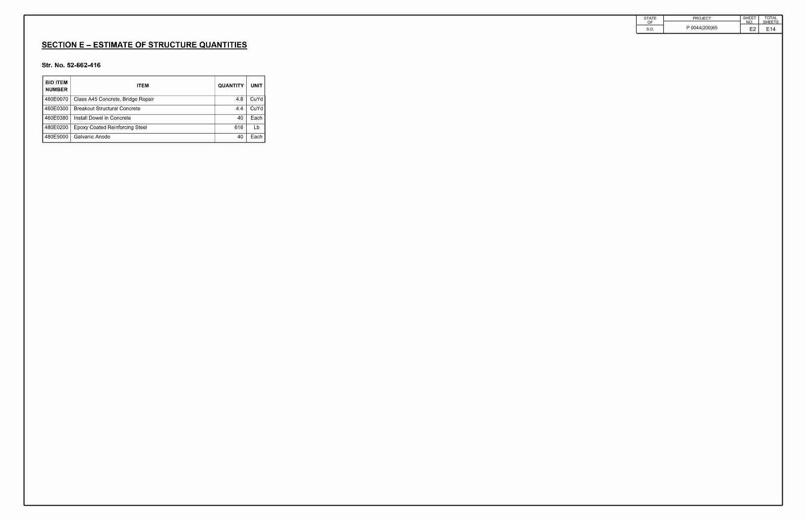
SECTION E - ESTIMATE OF STRUCTURE QUANTITIES
Str. No. 52-662-416
BID ITEM ITEM QUANTITY UNIT
NUMBER
460E0070 Class A45 Concrete, Bridge Repair 4.8 CuYd
460E0300 Breakout Structura l Concrete 4.4 CuYd
460E0380 Install Dowel in Concrete 40 Each
480E0200 Epoxy Coated Reinforcing Steel 616 Lb
480E5000 Galvanic Anode 40 Each

SHEET TOTALSHEETS
STATE PROJECTNO.OF
P 0044(200)65S.D.
106' - 3 %" Overall Bridge LengthBegin Bridge End Bridge
33'-1 7/8" 33'- 1 7/8"40' - 0"
\% \
\ (k'^0-^0-
lie-
W'-v \ \\\\ \ \
%, \\ \- \'CM
\\Ae>®" \\N\''CM
\ \ \V Ni\ \\ Modify End Block. See CONCRETE
BREAKOUT DETAILS and END BLOCK MODIFICATION DETAILS
Modify End Block. See CONCRETE BREAKOUT DETAILS and END
BLOCK MODIFICATION DETAILS\ \\coCO
jc: \ \\a. O IAICM \ \\LO
N.
\ \\CQ
•Q \ \\5 COo© OC CO
I-O -V0J-cooM-o CQ \ \M- \Oco
\o \\coCM \ \co \OCO
jc: \CL LO \\CM \ Modify End Block. See CONCRETE
BREAKOUT DETAILS and END BLOCK MODIFICATION DETAILS
Modify End Block. See CONCRETE BREAKOUT DETAILS and END
BLOCK MODIFICATION DETAILS
\\N.
\ \\
(5e §sV\ \\ T1\\x\CM \\
\\\CM
\W\v \\\\\>V'PLAN
INDEX OF BRIDGE SHEETS -Sheet No. 1 - Layout for Upgrade
Sheet No. 2 - Estimate of Structure Quantities and Notes
Sheet No. 3 - Notes (Continued)
Sheet No. 4 - Concrete Breakout Details Sheet No. 5 - End Block Modification Details (A)
Sheet No. 6 - End Block Modification Details (B)
Sheet No. 7 - End Block Modification Details (C)
Sheet No. 8 - Standard Plates 460.02 & 630.92 Sheet No. 9 thru 12 - Original Construction Plans
LAYOUT FOR UPGRADEFOR
106’ - 3 %" CONTINUOUS CONCRETE BRIDGE30° SKEW R.H.F.
SEC. 31-T1S-R12E P 0044(200)65
30’ - 0" ROADWAY OVER SWINE HART CREEK STR. NO. 52-662-416 PCN 05J8
PENNINGTON COUNTY S. D. DEPT. OF TRANSPORTATION
0OF@JULY 2019
DESIGNED BY CK. DES. BY JKI/TJM
DRAFTED BYPLANS BY:OFFICE OF BRIDGE DESIGN, SOUTH DAKOTA DEPARTMENT OF TRANSPORTATION
EJA EJAPENN05J8 05J8AA01 IRIDGE ENGINEER
E3 E14
E4 E14
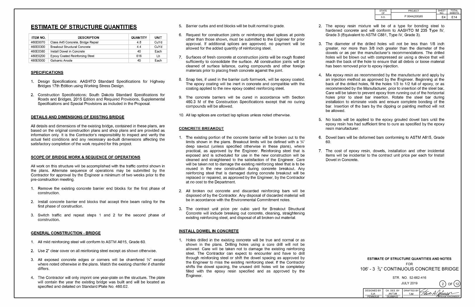
ESTIMATE OF STRUCTURE QUANTITIES
ITEM NO. DESCRIPTION QUANTITY UNIT
460E0070 Class A45 Concrete, Bridge Repair 4.8 CuYd
460E0300 Breakout Structural Concrete 4.4 CuYd
460E0380 Install Dowel in Concrete 40 Each
480E0200 Epoxy Coated Reinforcing Steel 616 Lb
480E5000 Galvanic Anode 40 Each
SPECIFICATIONS
1. Design Specifications: AASHTO Standard Specifications for Highway Bridges 17th Edition using Working Stress Design.
2. Construction Specifications: South Dakota Standard Specifications for Roads and Bridges, 2015 Edition and Required Provisions, Supplemental Specifications and Special Provisions as included in the Proposal.
DETAILS AND DIMENSIONS OF EXISTING BRIDGE
All details and dimensions of the existing bridge, contained in these plans, are based on the original construction plans and shop plans and are provided as information only. It is the Contractor's responsibility to inspect and verify the actual field conditions and any necessary as-built dimensions affecting the satisfactory completion of the work required for this project.
SCOPE OF BRIDGE WORK & SEQUENCE OF OPERATIONS
All work on this structure will be accomplished with the traffic control shown in the plans. Alternate sequence of operations may be submitted by the Contractor for approval by the Engineer a minimum of two weeks prior to the pre-construction meeting.
1. Remove the existing concrete barrier end blocks for the first phase of construction .
2. Install concrete barrier end blocks that accept thrie beam railing for the first phase of construction .
3. Switch traffic and repeat steps 1 and 2 for the second phase of construction.
GENERAL CONSTRUCTION - BRIDGE
1. All mild reinforcing steel will conform to ASTM A615, Grade 60.
2. Use 2" clear cover on all reinforcing steel except as shown otherwise .
3. All exposed concrete edges or corners will be chamfered %" except where noted otherwise in the plans . Match the existing chamfer if chamfer differs.
4. The Contractor will only imprint one year-plate on the structure. The plate will contain the year the existing bridge was built and will be located as specified and detailed on Standard Plate No. 460.02.
5. Barrier curbs and end blocks will be built normal to grade.
6. Request for construction joints or reinforcing steel splices at points other than those shown , must be submitted to the Engineer for prior approval. If additional splices are approved , no payment will be allowed for the added quantity of reinforcing steel.
7. Surfaces of fresh concrete at construction joints will be rough floated sufficiently to consolidate the surface . All construction joints will be cleaned of surface laitance, curing compounds and other foreign materials prior to placing fresh concrete against the joint.
8. Snap ties, if used in the barrier curb formwork, will be epoxy coated. The epoxy coating will be inert in concrete and compatible with the coating applied to the new epoxy coated reinforcing steel.
9. The concrete barriers will be cured in accordance with Section 460.3 M of the Construction Specifications except that no curing compounds will be allowed.
10. All lap splices are contact lap splices unless noted otherwise.
CONCRETE BREAKOUT
1. The existing portion of the concrete barrier will be broken out to the limits shown in the plans. Breakout limits will be defined with a %" deep sawcut (unless specified otherwise in these plans), where practical, as approved by the Engineer. Reinforcing steel that is exposed and is scheduled for use in the new construction will be cleaned and straightened to the satisfaction of the Engineer. Care will be taken not to damage the existing reinforcing steel that is to be reused in the new construction during concrete breakout. Any reinforcing steel that is damaged during concrete breakout will be replaced or repaired, as approved by the Engineer, by the Contractor at no cost to the Department.
2. All broken out concrete and discarded reinforcing bars will be disposed of by the Contractor. Any disposal of discarded material will be in accordance with the Environmental Commitment notes.
3. The contract unit price per cubic yard for Breakout Structural Concrete will include breaking out concrete, cleaning, straightening existing reinforcing steel, and disposal of all broken out material.
INST ALL DOWEL IN CONCRETE
1. Holes drilled in the existing concrete will be true and normal or as shown in the plans. Drilling holes using a core drill will not be allowed . Care will be taken not to damage the existing reinforcing steel. The Contractor can expect to encounter and have to drill through reinforcing steel or shift the dowel spacing as approved by the Engineer to miss the existing reinforcing steel. If the Contractor shifts the dowel spacing, the unused drill holes will be completely filled with the epoxy resin specified and as approved by the Engineer.
I STATE I PROJECT I SHEET I TOTAL OF _r--~~~~~~~~""i-~N!Q.0 . ......1...§Si!:!JHE~EilTSLJ
I S.D. I P 0044(200)65 I I
2. The epoxy resin mixture will be of a type for bonding steel to hardened concrete and will conform to AASHTO M 235 Type IV, Grade 3 (Equivalent to ASTM C881, Type IV, Grade 3).
3. The diameter of the drilled holes will not be less than 1/8 inch greater, nor more than 3/8 inch greater than the diameter of the dowels or as per the manufacturer's recommendations . The drilled holes will be blown out with compressed air using a device that will reach the back of the hole to ensure that all debris or loose material has been removed prior to epoxy injection .
4. Mix epoxy resin as recommended by the manufacturer and apply by an injection method as approved by the Engineer. Beginning at the back of the drilled holes, fill the holes 1/3 to 1/2 full of epoxy, or as recommended by the Manufacturer, prior to insertion of the steel bar. Care will be taken to prevent epoxy from running out of the horizontal holes prior to steel bar insertion. Rotate the steel bar during installation to eliminate voids and ensure complete bonding of the bar. Insertion of the bars by the dipping or painting method will not be allowed.
5. No loads will be applied to the epoxy grouted dowel bars until the epoxy resin has had sufficient time to cure as specified by the epoxy resin manufacturer.
6. Dowel bars will be deformed bars conforming to ASTM A615, Grade 60.
7. The cost of epoxy resin, dowels, installation and other incidental items will be incidental to the contract unit price per each for Install Dowel in Concrete.
ESTIMATE OF STRUCTURE QUANTITIES AND NOTES
FOR
106' - 3 ~/ CONTINUOUS CONCRETE BRIDGE
STR. NO. 52-662-416
JULY2019 G)oF@ I DESIGNED BY .1 CK. DES. BY I DRAFTED BY 1,,.-:::-.,L- /I /I §
EJA JKlfTJM TJM 170,,b ,t.J( Mui · "trl--PENNn• ,a ns 1><MAD2 I /BRIDGE ENGINEER
E5 E14
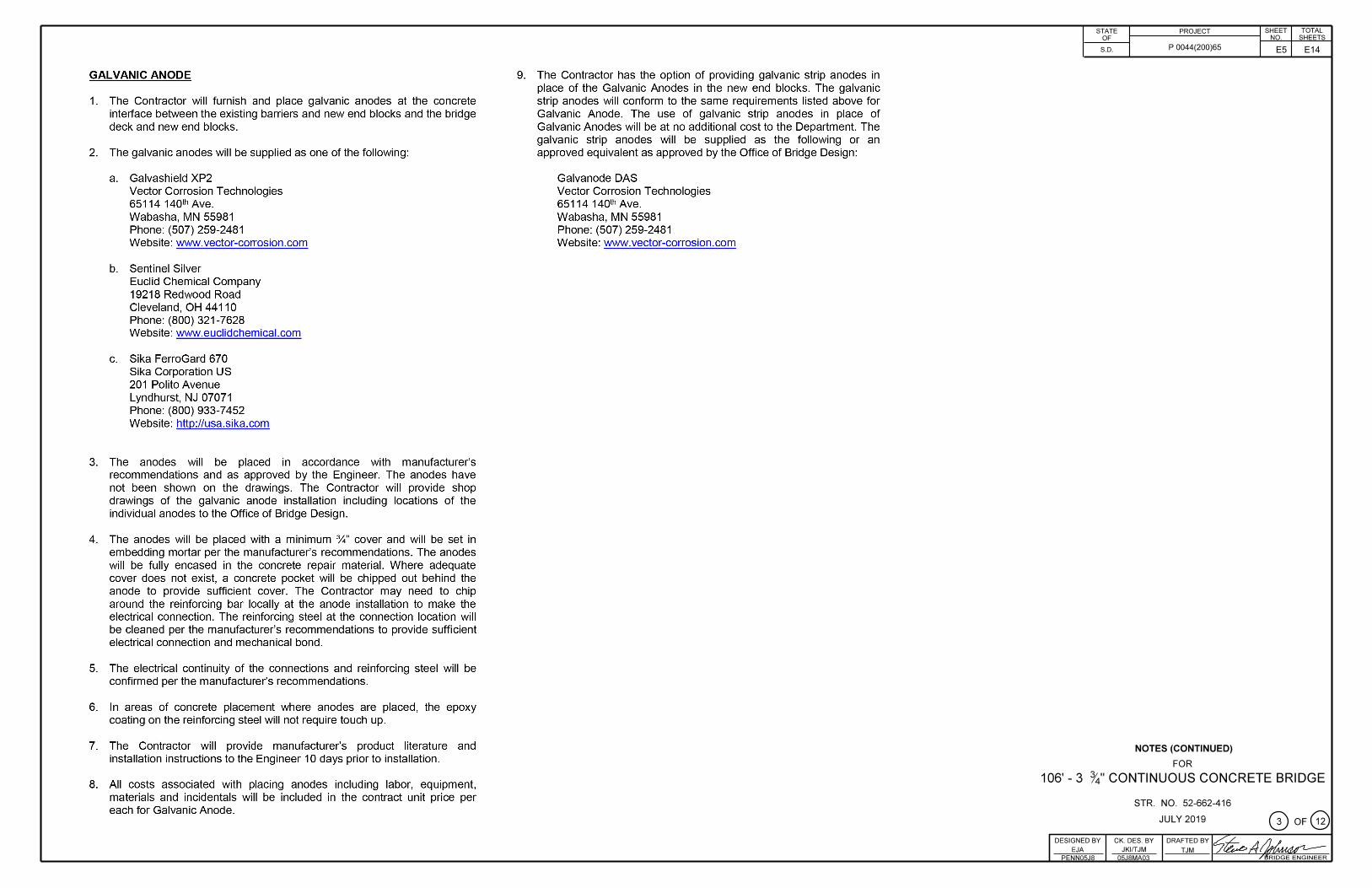
GALVANIC ANODE
1. The Contractor will furnish and place galvanic anodes at the concrete interface between the existing barriers and new end blocks and the bridge deck and new end blocks.
2. The galvanic anodes will be supplied as one of the following :
a. Galvashield XP2 Vector Corrosion Technologies 65114 1401h Ave. Wabasha, MN 55981 Phone: (507) 259-2481 Website: www.vector-corrosion.com
b. Sentinel Silver Euclid Chemical Company 19218 Redwood Road Cleveland, OH 44110 Phone: (800) 321-7628 Website: www.euclidchemical.com
c. Sika FerroGard 670 Sika Corporation US 201 Polito Avenue Lyndhurst, NJ 07071 Phone: (800) 933-7452 Website: http://usa.sika.com
3. The anodes will be placed in accordance with manufacturer's recommendations and as approved by the Engineer. The anodes have not been shown on the drawings. The Contractor will provide shop drawings of the galvanic anode installation including locations of the individual anodes to the Office of Bridge Design.
4. The anodes will be placed with a minimum %" cover and will be set in embedding mortar per the manufacturer's recommendations . The anodes will be fully encased in the concrete repair material. Where adequate cover does not exist, a concrete pocket will be chipped out behind the anode to provide sufficient cover. The Contractor may need to chip around the reinforcing bar locally at the anode installation to make the electrical connection. The reinforcing steel at the connection location will be cleaned per the manufacturer's recommendations to provide sufficient electrical connection and mechanical bond .
5. The electrical continuity of the connections and reinforcing steel will be confirmed per the manufacturer's recommendations .
6. In areas of concrete placement where anodes are placed, the epoxy coating on the reinforcing steel will not require touch up.
7. The Contractor will provide manufacturer's product literature and installation instructions to the Engineer 10 days prior to installation.
8. All costs associated with placing anodes including labor, equipment, materials and incidentals will be included in the contract unit price per each for Galvanic Anode.
9. The Contractor has the option of providing galvanic strip anodes in place of the Galvanic Anodes in the new end blocks. The galvanic strip anodes will conform to the same requirements listed above for Galvanic Anode. The use of galvanic strip anodes in place of Galvanic Anodes will be at no additional cost to the Department. The galvanic strip anodes will be supplied as the following or an approved equivalent as approved by the Office of Bridge Design :
Galvanode DAS Vector Corrosion Technologies 65114 1401h Ave. Wabasha, MN 55981 Phone: (507) 259-2481 Website: www.vector-corrosion.com
I STATE I PROJECT I SHEET I TOTAL OF r--~~~~~~~~""t-.liNOQ..__j_..§S!i!HE~ETI§Sl....J
I S.D. I P 0044(200)65 I I
NOTES (CONTINUED)
FOR
106' - 3 ~/ CONTINUOUS CONCRETE BRIDGE
STR. NO. 52-662-416
JULY2019 G)oF@ I DESIGNED BY I CK. DES. BY I DRAFTED BY I~ .,L- /I /I ;
EJA JKlfTJM TJM 1-/0,,b HI Jf/M "rl--PENNns1R ns1RMAD3 I /BRIDGE ENGINEER

TOTALSHEETS
SHEETSTATE PROJECTNO.OF
P 0044(200)65S.D.
1b*'12'-6"12' -6"Begin Bridge End Bridge
12' -0" 6" 12'-0".61
V)\\ \\
( /CM
CMCM--J Y--M- M-
\ /A\~~
\) \ \
\\
☆ Limits of Concrete Breakout ☆ Limits of Concrete BreakoutSalvage Existing B21 Bars Salvage Existing B21 Bars
PLAN(Phase 1 shown, Phase 2 similar opposite hand)
V/A Shaded areas indicate limits of concrete breakout.■Salvage Existing B21 Bars
Salvage 2' - 6" of existing bar for lap splice
$ Concrete shading and all reinforcing steel not shown for clarity.
The approximate limits of concrete breakout are shown. Actual limits of concrete breakout shall be such that the construction joint from the previous end block modification is completely removed.
Existing B14 Bars Existing B14 Bars
☆ Limits of Concrete] fit Breakout \ jlT
jijSalvage Existing] >j
C1 Bars \ |||
I Existing n Overlay
I Existing n Overlay
r☆ Limits of Concrete Breakouti/
iSalvage Existing"] '
C1 ears_p^[' // ESTIMATED QUANTITIESi ik«-
$ SECTION B - B
■i\ Iik™$ SECTION A-A
QUANTITYITEM UNITPhase 1 Phase 2
CuYd 2.2 2.2Breakout Structural Concrete
Each end block will require 1.1 CuYd of Breakout Structural Concrete.
ISOMETRIC VIEW(Phase 1 End Blocks shown, Phase 2 similar opposite hand)
:"T Existing B14 Bars Existing B14 Bars Existing B14 Bars CONCRETE BREAKOUT DETAILSL__ -X- Salvage Existing B14 BarsFORExisting
OverlayExistingOverlay Existing
Overlay 106' - 3 %" CONTINUOUS CONCRETE BRIDGE30° SKEW R.H.F.
SEC. 31-T1S-R12E P 0044(200)65
☆ Limits of Concrete Breakout* Limits of I
Concrete Breakout \* Limits of Concrete BreakoutIII III III 30' - 0" ROADWAY
OVER SWINE HART CREEK STR. NO. 52-662-416
Salvage Existing-\ . i |l C1 Barejj||
Salvage Existing C1 Bars Salvage Existing-\ . Ill
C1 BarsJ^.;/ / /wiLit- it,iu u ■11
PENNINGTON COUNTY S. D. DEPT. OF TRANSPORTATION
♦ SECTION C - C ♦ SECTION D - D $ SECTION E-E
© OF©JULY 2019
DESIGNED BY CK. DES. BY JKI/TJM
DRAFTED BYEJA EJA
PENN05J8 05J8AA04 IRIDGE ENGINEER
E6 E14

TOTALSHEETS
SHEETSTATE PROJECTNO.OF
P 0044(200)65S.D.
v /\—826 — 3 - B25 I— 3 - D2\ Existing B21 bars
I
z77 <MC3 C2C10 -4 M kC9 C8 C7 C6 C5 C4 CM
1
3-824 N.D3 E ,\\
8233 - 827 D3V--
3" 8" 7" 1'-5" V-5"8' - 0"r-6" 3' - 0" — -)f Existing B14 bars \
12' -6"
.4F G H J K L
0PLAN 0
0
^ - -l__
ISOMETRIC VIEWB27—
10 Spaces @ 12" = 10' - 0" 9" 1'-0"
B25 —824D2A
T T TID3 t T T/t t t
C10 C9 C8 C7 C6 C5 C4 C3 C2 \iI I I\T T
r- ri ii i ii i i
i i \n -p E+
Top of Existing OverlayI IB23 L* 2 - S26I I \Existing B21 barsII II I I END BLOCK MODIFICATION DETAILS (A)
FOR
106' - 3 %" CONTINUOUS CONCRETE BRIDGE30° SKEW R.H.F.
SEC. 31-T1S-R12E P 0044(200)65
II II ir
—-X- 2 - Existing B14 bars2' - 0" (Minimum Lap Length)I30’ - 0" ROADWAY OVER SWINE HART CREEK STR. NO. 52-662-416
Existing C1 barsi
L — -
ELEVATIONPENNINGTON COUNTY
S. D. DEPT. OF TRANSPORTATION■¥r Lap Bars
©OF©JULY 2019
DESIGNED BY CK. DES. BY JKI/TJM
DRAFTED BYEJA EJA
PENN05J8 05J8RA05 IRIDGE ENGINEER
E7 E14
SHEET TOTALSHEETS
STATE PROJECTNO.OF
P 0044(200)65S.D.
\\\ v-3-D2
*626—,3 - B25— \Existing B21 bars\I-
CM C2 C3f- C10C4 C5 C6 C7 C8 C9CM CM 3M- Oa
3-B24N. D3
llB23 D3 3 - B27\ \
* Existing B14 bars-* 1'-5" V - 5" 7" 8" 3"
8'-O' 3' - 0" r-6"12'-6"
PLAN
//
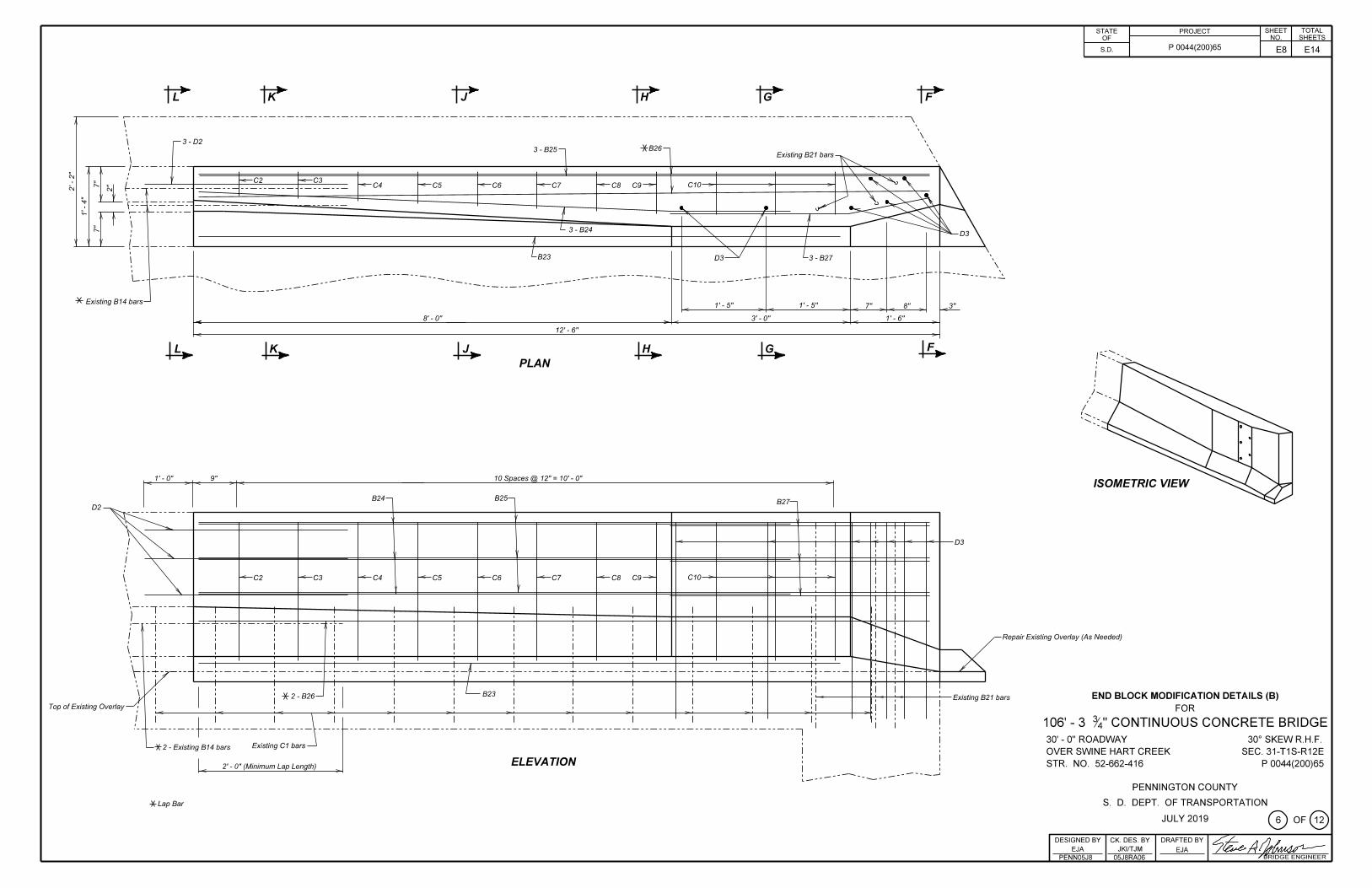
r-o" 10 Spaces @ 12" = 10' - 0"9" ISOMETRIC VIEWB25B24— 4 B27—
D2
T T TI D3rT T
I t t t\ C10C2 C3 C4 C5 C 6 C7 C8 C9 T I I\ T T T
“T 1 iI I Repair Existing Overlay (As Needed)
\ 1 I I
V -1 1 -I-
I I I\ B23 END BLOCK MODIFICATION DETAILS (B)FOR
106' - 3 %" CONTINUOUS CONCRETE BRIDGE30° SKEW R.H.F.
SEC. 31-T1S-R12E P 0044(200)65
-)f 2 - B26 — Existing B21 barsTop of Existing Overlay I I I
/ I I I“I
30’ - 0" ROADWAY OVER SWINE HART CREEK STR. NO. 52-662-416
Existing C1 bars—-)f 2 - Existing B14 bars IELEVATION2' - 0" (Minimum Lap Length) I
PENNINGTON COUNTY S. D. DEPT. OF TRANSPORTATION-X-Lap Bar
©OF@JULY 2019
DESIGNED BY CK. DES. BY JKI/TJM
DRAFTED BYEJA EJA
PENN05J8 05J8RA06 IRIDGE ENGINEER
E8 E14
TOTALSHEETS
SHEETSTATE PROJECTNO.OF
P 0044(200)65S.D.
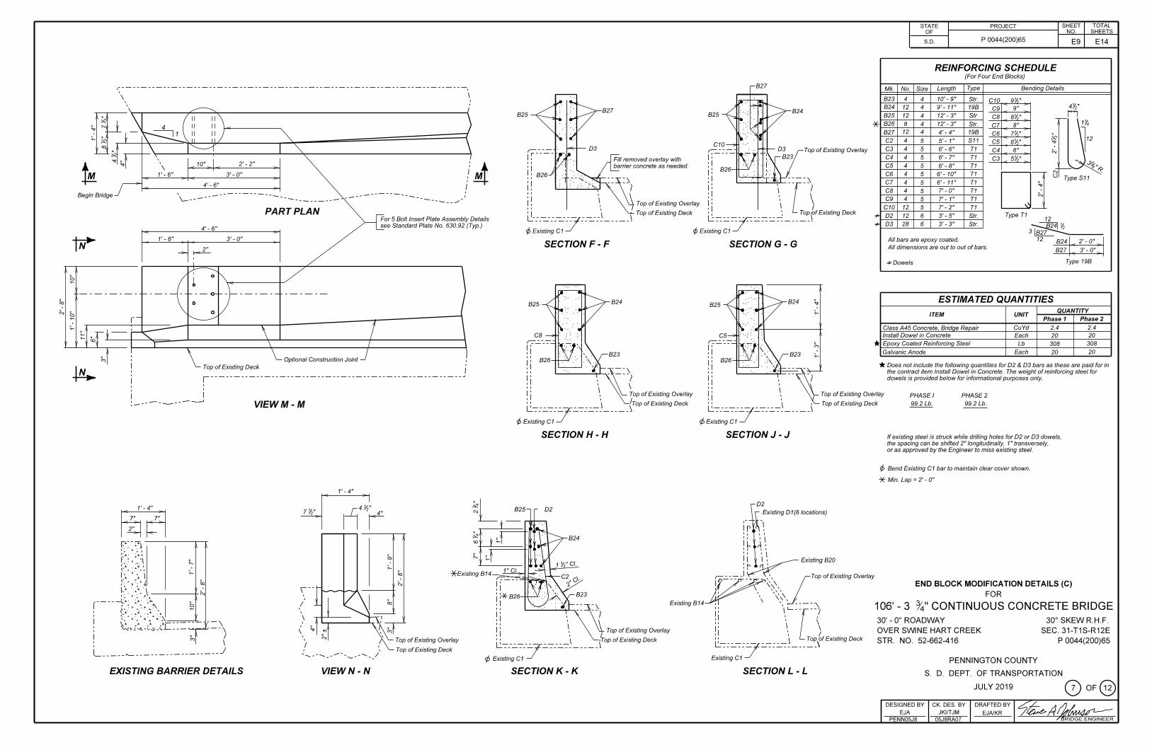
REINFORCING SCHEDULE(For Four End Blocks)
r—B27 TypeLength Bending DetailsMk. No. Size\\ B23 10' -9"4 4 Str. C10 c 91/2" 4V2"B24 19B12 4 9'- 11" 9"C9B27 B24 nB25 B25 B25 12'-3" Str12 4 8%"C8II II
1%i * B26 8 4 12' -3" Str. 8"C7II IIN-'f 412 4 19BB27 4'-4"M 7V?"C6II II / V 12C2 4 S115 5'- 1"11 4 6%"C5C10
D3 D3 C3 4 5 6' - 6" T1Top of Existing Overlay C4 6' CM
T*P r-B23 C4 T14 5 6' - 7" 51/2"C3Fill removed overlay with barrier concrete as needed.
•M- I10" 2' - 2" iw
i C5 4 5 6'-8' T1I\ J B26-I CMC6 4 T15 6'- 10"1'-6" 3' - 0" B26 (jI Type S11rjvr::z:\:\I C7 4 6'- 11" T154' -6" I o-1 )\ C8 4 7' - 0" T15IBegin Bridge \ \ CMI C9 4 T15 7'- 1"\ \Top of Existing Overlay Top of Existing Deck
\/ / C10 12 7' - 2"5 T1IPART PLAN i Top'Of Existing Deck Type T1D2 12 6 3' - 5" Str.liJ =t=\ \l_-For 5 Bolt Insert Plate Assembly Details see Standard Plate No. 630.92 (Typ.)
12D3 28 6 3'-3" Str. B24\ y24'-6" 0 Existing C1 0 Existing C1 3 | B27
V - 6" 3' -0" 12All bars are epoxy coated.All dimensions are out to out of bars.
2'-0"B24SECTION F-F SECTION G - GN 2' B27 3' - 0"
Type 19B=*= Dowels
oo AESTIMATED QUANTITIESB24B24CO o B25 •sj-B25
QUANTITYoCM ITEM UNIToPhase 1 Phase 2
v V V CuYd 2.4 2.4Class A45 Concrete, Bridge RepairInstall Dowel in ConcreteC8 Each 20C5 20Epoxy Coated Reinforcing Steel Lb 308308r CO
Y ■I I Galvanic Anode Each 20 20B23 B23Optional Construction Joint B26 B26-co \ \ ★ Does not include the following quantities for D2 & D3 bars as these are paid for in
the contract item Install Dowel in Concrete. The weight of reinforcing steel for dowels is provided below for informational purposes only.
I I ITop of Existing Deck Z_WiN, t )lri i i\\ \Top of Existing Overlay Top of Existing Deck
Top of Existing Overlay y— Top of Existing Deck
I PHASE I 99.2 Lb.
PHASE 2 99.2 Lb.
I I I/•VIEWM-M \ \ \LZ LZ0 Existing C1 0 Existing C1
SECTION H - H SECTION J - J If existing steel is struck while drilling holes for D2 or D3 dowels, the spacing can be shifted 2" longitudinally, 1" transversely, or as approved by the Engineer to miss existing steel.
0 Bend Existing C1 bar to maintain clear cover shown. -)f Min. Lap -2'- 0"
1'-4"
D2&4V2"V - 4" B25 D27V2" Existing D1(6 locations)CMr ir;!rf^ -
7" 7"
2"B24 \lid \uu\COp:--|
inO) Existing B201VSLN. ! p • o\
1" Cl.Existing B14co\ Top of Existing OverlayC2i END BLOCK MODIFICATION DETAILS (C)Y\
\ %\
OD CNJ . 7 \Ir".1 FORCM B23■¥rB26 )S\Existing B14r / CO 106’ -3 ?
4 CONTINUOUS CONCRETE BRIDGE30° SKEW R.H.F.
SEC. 31-T1S-R12E P 0044(200)65
II— A' \ o ;\< /) ii.•-A____= 30' - 0" ROADWAY OVER SWINE HART CREEK STR. NO. 52-662-416
I \\ \1 \—\ Top of Existing Overlay Top of Existing Deck
\ +r II //I CM Top of Existing DeckTop of Existing Overlay Top of Existing Deck
00 s\ \LL-_-“\/VL /0 Existing C1 Existing C1 PENNINGTON COUNTY
S. D. DEPT. OF TRANSPORTATIONEXISTING BARRIER DETAILS SECTION K - K SECTION L - LVIEW N - N
0OF©JULY 2019
DESIGNED BY CK. DES. BY JKI/TJM
DRAFTED BY EJA/KREJA
PENN05J8 05J8RA07 IRIDGE ENGINEER
E9 E14
E10 E14
%" 1 Y,"
Year Plate See Note 2 (c)
17"
2w 1" 2w 1" 2w 1" 2Y,"
g (OJ PLACE PLACE
APPROPRIATE APPROPRIATE
NUMBER NUMBER
HERE HERE
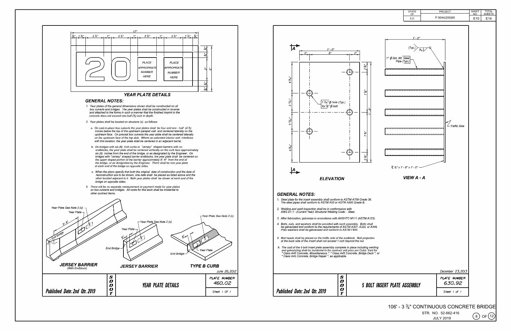
YEAR PLATE DETAILS GENERAL NOTES: 1. Year plates of the general dimensions shown shall be constructed on all
box culverts and bridges. The year plates shall be constructed in reverse and attached to the forms in such a manner that the finished imprint in the concrete does not exceed one-half (Y,) inch in depth.
2. Year plates shall be located on structure (s) as follows:
1 Y."
a. On cast-in-place box culverts the year plates shall be four and one - half (4 Y,) inches below the top of the upstream parapet wall and centered laterally on the upstream face. On precasf box culverts the year plate shall be centered laterally on the upstream face of the top slab. Where an extended interior wall interferes with this location, the year plate shall be centered in an adjacent barrel.
b. On bridges with six (6) inch curbs or "Jersey" shaped barriers with no
%"
endblocks, the year plate shall be centered vertically on the curb face approximately six (6) inches from the end of the bridge, or as designated by the Engineer. On bridges with "Jersey" shaped barrier endblocks, the year plate shall be centered on the upper sloped portion of the barrier approximately 5'- 6" from the end of the bridge, or as designated by the Engineer. There shall be one year plate at each end of the bridge on opposite sides.
c. When the plans specify that both the original date of construction and the date of reconstruction are to be shown, one date shall be placed as fisted above and the other located adjacent to it. Both year plates shall be shown at each end of the bridge on opposite sides.
3. There will be no separate measurement or payment made for year plates on box culverts and bridges. All costs for this work shall be incidental to other contract items.
End Bridge
~
~
1,., (0
~
~
Year Plate See Note 2 (c)
JERSEY BARRIER (With Endblock)
JERSEY BARRIER TYPES CURB
Published Date: 2nd Otr. 2019
s 0 0 0 T
YEAR PLATE DETAILS
June 26. 2012
PLATE NUMBER
460.02
Sheet I Of I
-, ,
' #
I eJ, , -, -
' I
GENERAL NOTES:
1' - O" 8"
I I
_ffi.__ ~·
I ffi2,
' - L-, __ ,
I
ELEVATION
1. Steel plate for the insert assembly shall conform to ASTM A709 Grade 36. The steel pipes shall conform to ASTM A53 or ASTM A500 Grade B.
2. Welding and weld inspection shall be in conformance with AWS D1.1 - (Current Year) Structural Welding Code - Steel.
3. After fabrication, galvanize in accordance with AASHTO M111 (ASTM A 123).
4. Bolts, nuts, and washers shall be provided with each assembly. Bolts shall be galvanized and conform to the requirements of ASTM A307, A325, or A449. Plain washers shall be galvanized and conform to ASTM F844.
5. Bolf heads shall be placed on the traffic side of the endblock. Bolf projection at the back side of the insert shall not exceed 1 inch beyond the nut.
6. The cost of the 5 bolt insert plate assembly complete in place including welding and galvanizing shall be incidental to the contract unit price per Cubic Yard for "Class A45 Concrete, Miscellaneous ", "Class A45 Concrete, Bridge Deck ", or "Class A45 Concrete, Bridge Repair", as applicable.
STATE OF
S.D.
1' - O"
(Typ.) >-r,-,6~,-*')
PROJECT
P 0044(200)65
---------------------------------
---------------------------------
Traffic Side
---------------------------------
Fe. Y,"x 1'-B"x 1'-0"
VIEW A-A
December 23.2013
PLATE NUMBER
SHEET TOTAL NO. SHEETS
s 0 0 0 T
5 BOLT INSERT PLATE ASSEMBLY 630.92
Published Date: 2nd Otr. 2019 Sheet I of I
106' - 3 %" CONTINUOUS CONCRETE BRIDGE STR. NO. 52-662-416
JULY 2019 G)oF@)
E11 E14
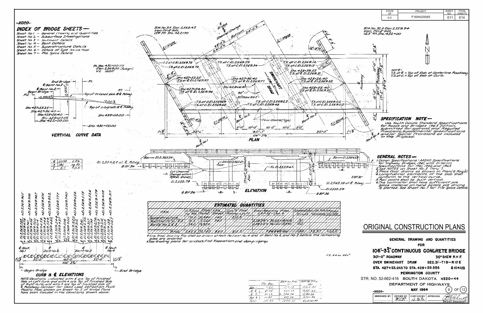
-XO!!O~ INDEX OF' BRIDGE SHEETS-Shec:f" /Yo. I -Sheer No. Z. -Sheer Na .3 -Sheet Na. 4- -S~ef- "*'- 5 -5'7eer N,,. 6 -.!ihe6-f No. 7 -
Ge~ra/ On:.1wi,'1;,· o.•-x:! c)t.x;nt-ifies S°<.lbsvrf'c1ce In~i9;::,rions Aburl7?c:nt- ~rails Senf" oerails Svper.slruc-f-t./re! Oetz,l.s Derc1ils of' li;pe lfA-IM .<:reel PIie S,P'ice ~ifs
P.I. .S,-a. 4.J'O rOO. 00 Elev. 2..569.00 /Svbar.} V.t:: I/GOO' /
. r/?/. i
. I P.r. - ·-' --;, R'.1:.r-t---:e..LU.._J -r7o?of" r,niShea' sbb t!!'-P. ~w7".
t--""'~::!:.c'.,-~r="11~~===t:=:;:::=====-~,%- I ~001' _,oh~,rad;@l:~4.
. ..5Y"a. -1'.YB~.oo.oo--f .J I I
r .St-a . ..,Jo+ao.oo
CURVE DAT.4
1.-i " ~ \) ~ ~ \a ~ ~ " ~
C\j " ~ ~ ~ ~ ~ ~ " ~ "' 't- 't lli Cl;) " \Ii Q\ ~ ~ ~ G\ ~ e-i ~ ~ ~ lti ~ \li
~ ~ ~ ~ ~ ~ ~ ~ ~ ~ ~ ~ ~ "I "J "I "' l\j "I "I "' "I l\j l\j l\j C\I
ii:! ~ ~ ~ ~ ~ ~ ~ ~ N. i;j iii :--: ~ ~
'ij ... ... .. 'ij 'ij ... 'ij ... I I I :;.. ~ 11\J · ~I\ (I) '. ~ ~1 ~ , I~ "I~~~~~ ~1" ~I ~~~ ~-'H\ l ~: ~ ~l'.i -~
1'1 'll " ~ "' ~ 'o "i li5, .,.. 'ts ~~ t ~ ~IC\J ~~ ~ ~ ~ ~ "iiG\ lli 0) \li a\ ~ \li ~ i ~ II\(\\ (l\ ~ ~ I~ <!i ;~ lli10'i (\\Ill\~ 0\ Oi l\\'\ ~!~~~~~ ~~~ '~ ~~ ~~ ~I ~ ~1 ~ ~i~ ~! ~ ~i ~ ~ I ~ "'!I'./ t,;t\J"J"l "J"I "l"l ""1"1 ~"I "l l"J "l ,"l "lil\J "li"l "li"l "I IC\/ ~I~ ~ ~ itj iii 4:i .'~ itj i~ ~ ti:\ ~ ilj ~iii:i ii:l i~iljii:j fil!iij (;:j ii;j ~ ! ~ 'lr .It '&_,I; ... *~* 'i< " 1< '"' ~l< "'"' ~'i.~'f.-
I
NO,£:E/evahons ,;,dicat-c:d wit"h ? ore Tof? of' .Finished :'Slob or Leff Cvrb .. and wfrh * ore lop or .Finished Sloh af- R19ht' c~rb1 ,:;r/d wtrh .a ore lop of' F/n,:shed Slab c1:f-£ .Roadwai: Camber fbr Dead" Load Def'/ec-hon PLUS Plosh"c .f'i~1-4; shown on Sheef- ·""-"· 5' o-F Br1dqe Plans hove ~en Included int-he e-levaf-1ons showr'J above.
\ \
\~i
-.2- ·S. ·- ELEVATION .
7 ~
~ Cine Sr~~/ iJc.,2,-,r"-'1 Pile .shall~ drive,? .:;rAbt./f; No./;e;,,;;, /lb.+ pnd o+ ii'enf No.Z dnd.No .. f.)jeff'o~ ;he ~rne:,lrvng f?iles dr~ orderi!:d- · ·
4S,:e Grad.ins' plans fbr Vnda.:.f;"f',.~d-£X<;dYO"f"1on:a.""'k.:f ,~n-,r ,r.7r4P-
1---s-"~"-l-E--11------PR_o_J_Ec_T ____ -1 s~~ET sWETtT~
S.D. P 0044(200)65
NOTE: r.s. c1I-~ = Top oF' Slab of-Cerm::rli~ ROeld~ T.S. arc. = i'op of' Slob of- ~rb .
ORIGINAL CONSTRUCTION PLANS
GENERAL · DRAWING AND QUANTITIES
FOR
106'-3\"coNTINUOUS CONC;RETE BRIDGE 30~0" ROADWAY 30•SKEW R.H .F.
OVER SWINEHART DRAW SEC.3f-TI S-R 12 E
STA. 427+53.245TO STA.428+59.555 S 1041(~
PENNINGTON COUNTY
STR. NO. 52-662-416 SOUTH DAKOTA HS20-44
DEPARTMENT OF HIGHWAYS
•X020- MAY 1964 0 OF@ DESIGNED BY DRAWN BY CHECKEDBY APPROVED
..Yt:C..iE__ ,J.B.S .

E12 E14
LENGTH
OVERALL
54co•
50!6"
6?!o·
73 !6"
eo ·-o ·
86!6" 93: 99~6"
106-3{(
112 - 6
119 '-0
. . " Cl al 12·cenlsn
Endof84 86 B8 and8IO L<l b
4 -814:-, 84'1 a,~ 82 /')
Al ot 2 ·"• ' ctrs. Top of Slab
Al al 'e" ctrs. Bollom of Slab
ENO SR4N
NOrt: Ploce ~ Al, A2, 6 A.3 af JO•Skow H.H.F.
15 '-o"
Sac.A-A Sec A-A 8 -Bars 84 al 24"
S«:.8 -8 Sec. 8 - B 8 -Bars Bl al 24 •
er-, sto,,e316in 12·
Cl at 12·maxi1THJm .... ~icol conslrt1clion j oin! l hru
l " curb only. Trim edges of joint with
14" b~el strips. Reinforcing m continuous l/1ru joint. ;,
"n" SH1J£TAIL "E"
83/ I I 4-a,2 , I
86
Al ai 2 ·in"ctrs. Top of Slab
Al ot''m" drs. Bo/lam of Sla/J
.. CENTER ~
LENGTH OVERALL
HALF LONGITUDINAL SECTIONAL VIEW ( Railing not shown. Soct ion cu l noor Curb.) (All dim.n•icns shown o n poro//el fo 4. &fwy)
8 -Bars Bl ot 24 "
, 15· 7-8ars 8 2 at 24•
s,;,x 26"9(11>. bolts .,.,,, WWf!Nin:11
-. al 3 ~!1· Clrs. ZOR>,q tl /or on,, br,~ .
c1o+12",r,a, .
STATE PROJECT SHEET TOTAL l---"0.;.F_ --lt--------------1 N SHEETS
S.D. P 0044(200)65
- NOTES-r~u no/es COW!f' Abutment, Superstructure, ond Railing De/oils . TM ~ rol {),at,ing lo, H eh
slrl.cft,r w,J/ show spans, ek!voti011s, and other necessory notes ond details.
DESIGN SPECIFICATIONS: A.A.SHO Spec,ficohons for H,ghwoy e,~s, /961, .,,,,, t,,n,,m 5/>«>ficohOM
for 1961, 1962 and 1%.3.
STRUCTURAL STEEL: All ~ ·, bolls ,ncluding .. ,,.Mr., and all 1>l• conn«1,ons ,n A/Jul'"""", and oil f1-
d'oins sllolf M paid for as Struclllol Sitt/.
REINFORCING STEEL.' All Ro,ntorc,ng 51.,,1 shall conform la A.SI M Spec;t;cations A.= and A/5 o,,,_,a,, Grad• I
CONCRE TE.' Class ll"Cancm• sl>olf <M,..lop a minimum allowable compress,·,_ slrMgl/l of 4,000P.s.i. al
28 days. All • xPoSl1d concrel, corners and t dgtts shall bt1 c/Jomftr ttd lo a 34 • /Httttl L11less no~ d olhe•r• is,.
If flltC'essary tr, facJ/itote constr f!ction, tronsver5'! construction joints may be mode ot tM quarter paints of
t och and any spon, odjocent to 1nterior Junts. All costs for expansion j oint filler and lar pope, shall be inclut*d in thtl unit pn ce bid ~ r cu. y d. for Closs 'A" Concr1tt1.
DESI GN DAT'A .' Oesign Lood,n9, HS 20 - 44 A.A.S H.O Uml stresses,ca,,crete fc = 1600 p.s.,:, n= 8 ;
Reinforcing Steel fs :: 20,000p.si(lnl. Grod, Sle• /) Equittolent fluid pressure of eorlh ot 40 it/ sq.ft.
Minimum Pi!• Loading= 2 4 tons fo, Timber Piling ond4.5 Ions for 8 8P36 S!Bdl 8Mrin9 Piles.(volues for on, pile)
-Rrlb lo a 2 "rodius Ah
,a DETAIL "D II
"n "
Sec.8 - 8 1 ,
Sec.A-A
sec B-
~ f~_-4__ ?4"· 8_-8 __ _
END CENIB
SPAN SPAN A l
No. .Size Length
16 ' 20' 8 8 i 5 JJ'.9"
18' 22'6" 100 '
20 ' 25' 112 ;
22' 27!6" 125
2 4 ' 30' 138
26' 32~6'' 151
28' 35' 16.J ' .JO' 3?' 6 " 196
32' 40' 06 5 39'0'
34 42 ' 6
3 45 33-9
•• 15 -Bars 86 al 12 "
15-Bars 8 7 al 12"
8 -Bars88 o/24 " I ' 24" 7-Bars 89 (If 24 •
8 -8°" 89 at 24" 7-BarsBIO at24"
1,2·
____ 7- Bors 8 ll ol 2 4 " : i2:! SECTION C-C
SECTION A-A~ As shown <>'ldn«e<t
SECTION 8-8 ( All S4CfiM• taken perpendicu lar to 4. l<dwg )
A2 84 -l ~
" ~ ~ ;,, § ,:! &
7 8 '0" 16 6
7 . 9'-5" 7 19c9 •
7 " : o " 1' 20!9'
8 12'6" 8 22:9 •
, 12'-6" 8 244
I:! l ~ " .... ~ as ,o, ~-"' ~ ~ -.J
15: 0 · 9 26'-9'
' 9 ; ,5 :0" 9 28 '9' , 9 17!0 " 9 30 '.9"
9 17>5" 16 10 32C9" 60
, 9 J 9' 6 " 10 34'9'
9 ,2/Co" 16 II 36'-9' 60
9
10
9 I()
DETAIL "F•
SLAB DATA REINFORCING SCHEDULE
812
,;?2 !3 "
,2 4!3
26'-5' . 9 i2a!3 " .:3! 6'
· 10 ,30'3'' 9 24'-6'
10 !32'3'' 15 10 26' 0"
,21! 5" , 10 34'.3 ' 21"-6'
2 4' 30 10 36' 3 29'0' 14 8
~~ ~~ <>[~
Leng/II of End Span = E Len Iii of Centar =C
LENGTH OVERALL
CAMBER DIAGRAM Camber is co/culoted for dead food plus plastic flow. Comber i s colcvlated thus vsing the 10 6 '-0"
Bridge as an i llustratiOf'I -" £ : JP 'ond C: 40; C/ 80 : 40/ 80= l /2, provide l/2 "comber (If cenltN of
Ct!nler span. The value.,; obtained for comber shall be added to /he proposed grade elettafions of
I~ resl)«tive stations to establish the elevations of lhe top of the finished roadway slab.
10
II
814 Cl A
e'o"
: e'o·
9 '.3 • , e:3• i 9 !3" I
8 15'6" 11'8
8 15-6 192
8
8
8
45'-o" 16 8
I.> ~
Sym. Al/I. f Brid,-
DETAIL "E " {TYpJCAL CONSTRVCTION JOINT)
DIMENSIONS
"1,'' "c" "d" "e l' "t " "q"
B'.5' 10 · , ,e · 2'0 10 " 1'-8" 2'.3"
10 " 2!fi" 2'6' IO" 3! 4" 2:9"
5-4' 3:0"
3'4" 3 '..J"
4'2'' 3! 5'
4 '.5 5-!J'' '6" 4 ,0 ·
5-J" 4 '.3
9 • 6'o" 4!6"
.,,. i " ,:2 · ( -9 ·
t'6 " ,,2 •
1'10 1'6"
1'4'' JC,o" 1'8 " 1'.J" 1!2 " ,:r / !6 " 1!11"
/ '.6" 1:_~· z.Lo t!B"
/'.9 " /'.3"
t '-6" 1'8"
\ LENGTH 8AR 8 ENDS
"k" ·m . .,,. OVERALL NOTE'A/1 dknen-
2:9• 11· 7 -l.," 54co• sions are out to 2c9• 11" e'2 " 50'.6 " oul of bars.
:9• 11" 91p · 67 '.d' 3 !9" 11" ,oil" 73'.5 " 4 '.7" 11· 1034 80'-o"
Cl . f 9!f 4 '.7" 11· I~~ 86' 6"
5 ' 6" 11" 1'-1'2° 93'-o" I '
S'tO" 10 " ,,2r 99c6 " []~ 5'.9" 10 " /-3 ;_," 106"3-'i
12 ' "' ' 6'.fi" 10 " 1'-4-i 112 ' 6 " ' _j T-6 " 10 · t '-6" 119 '-o" Type Tl
ORIGINAL CONSTRUCTION PLANS DETAILS OF SUPERSTRUCTURE
FOR
106'-3~ 1 CONTINUOUS CONCRETE BRIDGE 30'-o" ROADWAY
OVER SWIN2HART ORAW 30• SKEW R.H. F.
SEC. 3I-T1S-R!2!::
STA. 427+53.245TO 428+59.555
PENNINGTON COUNTY
S O UTH DAK O TA
S 1041 (5 )
HS20· 44
DEPARTMENT OF H IGHWAYS
STR. NO. 52-662-416 MAY 1964 @ OF@ CHECKE D BY AP PROVED
• Includes Slobs and curbs d11·ect1y over abutment . kvis,d from NCC{;·.30-00-1/9-1-2 lo skew ELS 5-f0-64-
DESIGNED B Y
CHv'. ( ~ DRA W N BY
RCM ~ s-- £
._) . <S .
E13 E14
"' ~ }.: ~
;:::! ·S ~ "' c1; ~ " " .. V)
I 1.
' I I I ;/
J.-f/ I· .
-.J ..._ •;i: I,..
l<J ~ 'I> '
" "'
..: ·\?' !I: .., .. ~ ~
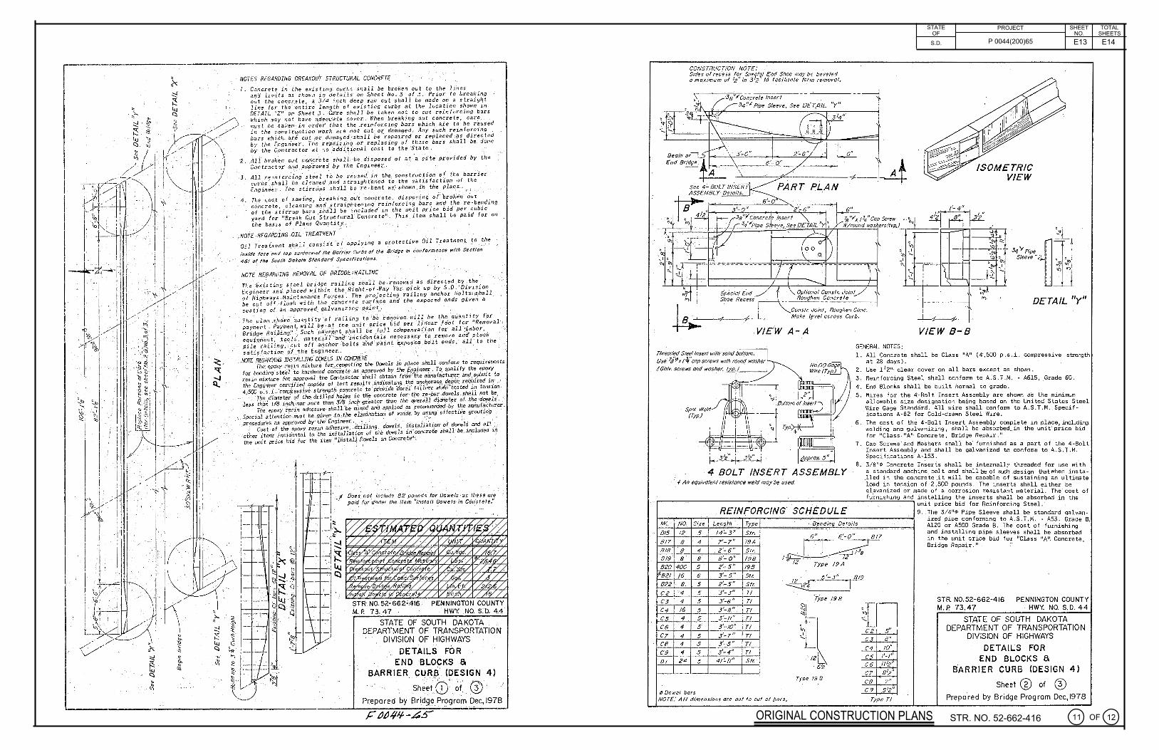
NOTES REGARDING BREAKOUf STRUCTURAL ,CONCRETE
I. Con crete i.n ihe existing curb:; ishall be broken out to the liii es and limits as. shown j.._ ,~ de tai-ls .or, 5.hcet No. 3 t}f .3. Prior to J;rca l..in9 o~t t he concr.et·e , a ·3; 4 in ch deep saw cut shall be made on a s traigl1t line for t/:le.· ·ent ire· length of existing· curb.s at t he l oca t io fJ ·sh own i'h . DETAIL HZ." on Sheet 3 . . C.~fre s'ha l l be t.1ken no t to cut rein!O·rcing bars which m:1 y not have a:de qu·a-te aoVer. -When breaking out. concrete, care .. must be · ta f<en · in urder that th~ .r ein_forc ing bars trh i c.h . ate t o be reused in · the· c.onstrU.ction ·work are not- cut_· or dr1 il1agcd. ,4ny Au.ch reinforci"ng , l~ars whi..ch.. a.ri cu e:.o:r da_ma~ed ·.shall be ··r ep-aired or re plac.ed :~s c!irec ~e d by thC [_ngin'ee·r .. Th~. ref}airinb· .ot ·CeJ?la ci ng· Of t hese bars s_h_a ll be. dOn e b y the C_ontrac .trir a.t no _"addit,i ~nal - cost to the --Sta te.. i
'2. A1} broken· Oi.Jt c On:c;·e.te ·shal .J.!·be disposed o f _ at:· ·~· s·itt! pro-vided by th e 'c.On!rac t ;r ·and app.ioved by "t he .Enginee~ ..
3 _ All ;einforc·i~g· s·t~el t'O_· be ·1·.eus-ed: ir1 ·t he.· construc·;ioii o { t he barrl.er curbs.·_.sha l l be cl eaned .and s tra ightened to _the sat1 sfac ti on of t he
_.Engin·Jer . The stirnips shall be '~e-ben t as: ·shown ~·n, the_ pla.~~~· ··. : : ,,
4. The Gos:t of sawing ·br eaking,: ou·t :, on~.r~ te-, d_isp~si.ng of 'br6ken OUt , cor.ciete. c l eaning' and _s traightening ~~in f ore in~ bar~ and·. the re - ben_ding of t he -s,tir·rup. ba.,r-s s_hit'll be .in_c ludc d 1n the unit pr i ce bid pe r _cubic y~rd for 11 Break Out ·s t'ructural" Concre·te11• • Thi s it~m shall be P,a1d for oo the ~asis of ·Plans Oua ri tit,Y, · ·
, NOTE REGARDING .OIL TREA'Tl,f£NT Oil Treatment shaH consis t of ·applying a protective Oil Treatment to t he
ins1de f~ctJ and top svr /~t;t!,of the Bor'f'l'.er c, .. rbs of f/:e Bridge ·in .C.onformonce wi th Section
· 4·6/ of the Sov/11 Ookoto Standard $pe~ificoli'!ns. · ' .
Docs .no~ include· 82 pounds for Dowels· -as tt1ese arf poi~ f~r under the item "lns!all Dowels-in Con<;:tete,"
snt N0.52~662~416 PENNINGTON COUNTY M. P. 73.4 7 HWY. NO. s:o. 4.4
STATE OF SOUTH DAKOTA . DEPARTMENT OF TRANSPORTATION . DIVISION OF HIGHWAYS
-[ ~ ~ .... -~ '
t~) DETAILS FOR
END BLOCKS Si BARRIER CURB (DESIGN 4)
- ' ' ; " "; ~ .... , ··f • . ...
, Sheet.Q) ~f· @' P(epare.d by B ri~9e_Pr9grom Dec, 1978
CONSTRUCTION NOTE: . Sides of r ec ess for Sp e1,tq/ E'.rJd $ hoe may be bevel ed o maximum of !2" in s2, 1 ~O .fcici /itolc form remova l ,
·3s"; c;n-~reie lnser /· 34 "1 Pipe S leeve, See DET.A IL
. "l I Specia(End "l Shoe Recess
6 "
7t, ";'x / 34 11 Cap Screw
STATE OF
S.D.
PROJECT SHEET TOTAL NO. SHEETS
P 0044(200)65
W/round was ers (typ, )-,--'---- r -'-=:=;o-,----",c-.--r
' ·'
DETA IL "y" '-~~ ~ VIE1W A-A
Cons I r. Join!, Roughen Cone, Make lfvel across Curb. i:=i
I · 3 1/ ' i. 312" i
"" ~ Bollom of 1nu::2_
Typ~~
~ I ApP(OX. 5 '' , I 4 BOLT INSERT ,4SSEMBLY
· / An eQ<Jivalenl resistance weld 17Joyoe· <Jsed.
VIEW 8-8
GENERAL NOTES :
1. All Co ncrete shall be Class "A" ( 4·,500 p .s .i. compr essive strength at 28 days ) .
2 . Use 1 1211• clear cover on al l bars e xcep t as shown . 3 . Rein forcing Steel s hall con form t o A.S . T .M. - A615 , .Grade GO.
4:. End Blocks s hall be built norrna l t o grade .
5 . l'lires for the 4:-Bolt I nser t Assembly a re s hown a s the minimum a llowable size designati on being based on t he Unite d Sta tes Steel Wire Gage Standard . .i.11 wire s hall con form tc, A. S .T .M. Specifi cations A-82 for Cold - dr awn Steel !'lire.
6. The cost of t he 4·-Bolt Insert Assembly complete i n place including we ldi ng and galvanizing , s hall be absorbed .. i n the uni t ' pri ce bi d for 11 Class 11 A11• Concrete , Bridge Repai r . 11•
7. Cap Scr ews · and l'/ashers s hall be· f urnished as a part o f t he 4:-Bol t I nser t Assen1bly and s ha ll be galvanized t o con form t o A.S. T. M. Specif ications· A-153 .
8 . 3 / 8",P Concrete I nserts s hall be internall i thr eaded for use w{th a s tanda r d machine . bolt and s hall t:e of such .des i gn that r,he n i ns ta lled i n t he concre t e .it will be capable o f s us tai ni ng a n ultimat e l oad i n ten.sion of ·2 ,500 poun ds . The inser ts s hall either be gl_avani zed or made o f a corr osion resis tan t material . The cost of
,.....~...,..~~~~~~~~~~~~~~~:.....:..:...:...:....~~~~~~~~fu~r~n~i~s~h~i~n~g~ a~n::!.d i nsta lling t he inser ts s hall be absorbed i n t he unit pr ice bid for Rein forcing Steel .
f-,.--;-~-----,-~R_E-'-1 N,..,_F_O--,R_c_,_N-'-G"-'-· _s_c.,,..H.:..· _£..;. .. _o_u.,..,...L_E _______ ..;..,f 9 . . The 3 / 4",P Pipe Sleeve s ha ll be s tandard gal va n . . Bending· De tails ized pipe c on formi ng to A.S. T .M . . A53 . Grade B,
Length M( NO. Size
Bt5 I? 5 / 4'-' 3 "
8 / 7 8 4 7 ' - 7 "
8/8 8 4 2 '-6"
819 8 8 a'- 0 11
820 400 5 2 '~ 5 "
82/ /6 6 3 '-5"
822 8 . 5 2 '- 5 "
C,2 •,4 5 3 '- 3 "
CJ 4 5 3'- 6 "
C4 /6 5 3 1- 8 "
cs 4 5 3 '~11"
C6 4 5 3 '- 10 "
C7. 4 5 3 '-? 11
CB 4 5 3'- 5 "
C9 4 5 3'- 4 "
O t 24 5 4 1'- I!"
6 Dowel bars
T e
Sir.
19A
Si r.
/98
/98
$tr.
St c
Tl
Tl
Tl Tl
Tl
Tl
Tl Tl S ir.
1
6u1
6 '~817
,~-y11~9 12 · Typ e l 9A
5 '- 3 " 819
· ~ fyp e /9 8
ti /2~
6'2
Type 19 B
in 5 '
C9 5 12"
Al20 o r A500 Grade B. The cost of furnishi ng a nd i ns talli ng pipe s leeves s hal l he absorbed i n the unit price bid . for -"Cl a ss 11A11: Concre t e, Br i dge Repair . "· ..
STR. N0.52-662-416 PENNINGTON COUNTY M. P. 73. 47 HWY. NO. S. D. 44
STATE OF SOUTH DAKOTA DEPARTMENT OF TRANSPORTATION
DIVISION OF HIGHWAYS
DETAILS FOR END BLOCKS Si
BARRI ER CU RB (DESIGN 4)
Sheet Cg) of ~ NOT£:All ' d im en sion s ar e out fa out of bars. Typr. Tl Prep a red by Br idge Program Dec, 1978
ORIGINAL CONSTRUCTION PLANS STR. NO. 52-662-416 @oF@

E14 E14
C-5? 815\. C6: [819 ( C4 (C7f B17(C8 ({9 Min Lan=/~9'~ r2- 0I
... 1 .,,. , ;, r If IJ J ~11-----1oe--1-....+-- ......+--l---,b>-f,-......,..J '
8 2 2 --1-1--i-.--,..,1 0 0 - l i 1. I I 8~~-t±~~:j!::~jr-=j:~;.;:;;;~~~o~-==t=il:':'=!::::::jE::1=:::j~=-=Ji==~~===ll==la=l.~ =l==~+-L_-+---1--, r- --- -_ -_-_,,__--.._.,.__-_,-._-__ ~- ltt-- -c...r-"!F-=-=--"'-t!'·-=--=-=c.:;i..;=-=- - - - - - - - - I- - -~n-=- --- -- -II I •
- L - Exis ting e-- -a,2 orB/4
1--,t---lf-+--fl--..L....-!f.1--ll-.__
I 11 I I Ef;51ing_, - I' I 1~--+:----l----ll---+-,.-; -+ ........ ---1--:--1--,- -+1-· - -11-<..--t---ii--1+----Jll-----t----i-~ g/@'1'},
: ~J r-- ·--- ---- ---------------------------
A ~ E'LE'VAT/ON
Se e DETAIL "z "tor Breakout dimension ond Ben ding, PLAN
SEC. 0-0 SEC.£-£
NOTE-in Tapered End Sections, rebend 820 bars where necessary to provide proper cover.
STR. N0.52-662-416 PENNINGTON COUNTY M. P. 73. 47 HWY. NO. S.D. 44
.3- 01
DETAIL "z"
STATE OF SOUTH DAKOTA DEPARTMENT OF TRANSPORTATION
DIVISION OF HIGHWAYS
DETAILS FOR END BLOCKS a
BARRIER CURB (DESIGN 4)
Sheet ' @ of @ Prepared by Bridge Program Dec,1978
STATE PROJECT SHEET TOTAL 1------"0::._F __ ~---__;..:..:.::.:::;.:c..;__ ____ NO. SHEETS
S.D. P 0044(200)65
ORIGINAL CONSTRUCTION PLANS
STR. NO. 52-662-416 @)oF@