section d: erosion and sediment control...
TRANSCRIPT

DAKOTA
SOUTH
STATE OFPROJECT
SHEETSHEETS
TOTAL
NH-PH 0085(20)26
Plot
Na
me -
385
CHARLES AVE.
CLIF
FST.
14A
21
28
2223
27
26
C
DEADWOOD
85
33
34
35
CEMETERY ST.
T 5
N
T 5
N
R 3 W
BEGIN NH-PH 0085(20)26
END NH-PH 0085(20)26
White
wood
Creek
WA
BAS
HA
VE.STEWART
ST.
RO
BE
NH
ANS
AV
E.
FRE
MONT
ST.
TE
RR
AC
ES
T.
BURLIN
GTON
ST.
PE
CK
ST.
CH
AR
LES
ST.
McGOVERNHIL
LRD.
1ST.
MILLS
ST.
ST.
LIN
COLN AVE.
SHE
RM
AN
ST.
DENVERAVE. DEADWOOD
ST.
MAIN
ST.
PINEST.
LEE
ST.
DEADW
OOD
AQUEDUCTCREEK
CITY CREEK
Station 94+64.00.
Station 13+22.93
Station 41+97.54
BEGIN MILL & OVERLAYEND GRADING
Station 54+44
BEGIN GRADINGEND MILL & OVERLAY
SECTION D: EROSION AND SEDIMENT CONTROL PLAN
U:\rd\prj\la
wr0
555\title
d.d
gn
File -
Plotting Date: 06/13/2014
Plot Scale -
1:2
00
Plotted Fro
m -
trpr1
3525
INDEX OF SHEETS
Standard Plates
Erosion and Sediment Control Plan Sheets
Erosion and Sediment Control Legend
Dewatering and Sediment Collection System Details
Stormwater Pollution Prevention Plan Checklist
Estimate with General Notes and Tables
General Layout with Index
D29 to D31
D13 to D28
D12
D11
D8 to D10
D2 to D7
D1
D1 D31

DAKOTA
SOUTH
STATE OFPROJECT
SHEETSHEETS
TOTAL
NH-PH 0085(20)26
...\prj\la
wr0
555\N
otesSection
D.d
gn
File -
Plotting Date: 06/19/2014
Plot Scale -
1:2
00
Plotted Fro
m -
trpr1
3525
D2 D31

DAKOTA
SOUTH
STATE OFPROJECT
SHEETSHEETS
TOTAL
NH-PH 0085(20)26
...\prj\la
wr0
555\N
otesSection
D.d
gn
File -
Plotting Date: 06/13/2014
Plot Scale -
1:2
00
Plotted Fro
m -
trpr1
3525
D3 D31

DAKOTA
SOUTH
STATE OFPROJECT
SHEETSHEETS
TOTAL
NH-PH 0085(20)26
...\prj\la
wr0
555\N
otesSection
D.d
gn
File -
Plotting Date: 06/13/2014
Plot Scale -
1:2
00
Plotted Fro
m -
trpr1
3525
D4 D31

DAKOTA
SOUTH
STATE OFPROJECT
SHEETSHEETS
TOTAL
NH-PH 0085(20)26
...\prj\la
wr0
555\N
otesSection
D.d
gn
File -
Plotting Date: 06/19/2014
Plot Scale -
1:2
00
Plotted Fro
m -
trpr1
3525
D5 D31

DAKOTA
SOUTH
STATE OFPROJECT
SHEETSHEETS
TOTAL
NH-PH 0085(20)26
...\prj\la
wr0
555\N
otesSection
D.d
gn
File -
Plotting Date: 06/19/2014
Plot Scale -
1:2
00
Plotted Fro
m -
trpr1
3525
D6 D31

DAKOTA
SOUTH
STATE OFPROJECT
SHEETSHEETS
TOTAL
NH-PH 0085(20)26
...\prj\la
wr0
555\N
otesSection
D.d
gn
File -
Plotting Date: 06/19/2014
Plot Scale -
1:2
00
Plotted Fro
m -
trpr1
3525
D7 D31

DAKOTA
SOUTH
STATE OFPROJECT
SHEETSHEETS
TOTAL
NH-PH 0085(20)26
...\prj\la
wr0
555\N
otesSection
D.d
gn
File -
Plotting Date: 06/13/2014
Plot Scale -
1:2
00
Plotted Fro
m -
trpr1
3525
D8 D31

DAKOTA
SOUTH
STATE OFPROJECT
SHEETSHEETS
TOTAL
NH-PH 0085(20)26
...\prj\la
wr0
555\N
otesSection
D.d
gn
File -
Plotting Date: 06/13/2014
Plot Scale -
1:2
00
Plotted Fro
m -
trpr1
3525
D9 D31

DAKOTA
SOUTH
STATE OFPROJECT
SHEETSHEETS
TOTAL
NH-PH 0085(20)26
...\prj\la
wr0
555\N
otesSection
D.d
gn
File -
Plotting Date: 06/13/2014
Plot Scale -
1:2
00
Plotted Fro
m -
trpr1
3525
D10 D31

DAKOTA
SOUTH
STATE OFPROJECT
SHEETSHEETS
TOTAL
NH-PH 0085(20)26
7
9
1
2
3
6
4
8 5
2
Flo
w
1"
Storage UnitWater and Sediment
Storage UnitWater and Sediment
Storage UnitWater and Sediment
Flow
FlowFlow
Flow
Flow
Flo
w
Flow
Flow
2"
3" gas
4" diesel
6" diesel
50-250
250-350
500-750
750-1000
1
1
1-2
2-3
30
5’-0"
6"
Floc. Bags Required
Gallon Treatment
No. of 500 K
Type
Pump
(gpm)
Flow Rate
(Hours)
After:
Expended
30-40
24-33
25-36
gallons of storm water)(Treats approximately 500,000
Handle to attach rope
(For Information Only)(Estimated Quantities)
water body.Return to natural
DEWATERING AND SEDIMENT COLLECTION SYSTEM
...\rd\prj\la
wr0
555\D
ewatering.d
gn
File -
Plotting Date: 06/13/2014
Plot Scale -
1:3
00
Plotted Fro
m -
trpr1
3525
www.acfenvironmental.com
1-800-223-9021
Richmond, VA Dirtbag 55
ACF Environmental Heavy Duty
www.iviindustries.com
1-800-659-5111 Filter Bags
Johnson City, NY Sediment
Indian Valley Industries, Inc. Non-woven
www.solhutec.com Bags
1-888-703-9889 Dewatering
SolHuTec Group, Inc. Taurus
www.spillcontainment.com
Phone: 1-800-764-9563 Bag
Jacksonville, FL Dewatering
UltraTech International, Inc. Ultra-
www.dandyproducts.com
Phone: 1-800-591-2284 Bag
Powell, OH Dewatering
Dandy Products, Inc. Dandy
Manufacturer Product
Known products available are listed below:
dewatering bags to capture sediment.
The Contractor may elect to use
http://www.soilmoist.com/
Phone: 1.216.475.8488
Cleveland, OH Tablets
JRM Chemical, Inc. FI-3500
http://www.innovativeturfsolutions.com/index.html
Phone: 1.513.317.8311
Cincinnati, OH
Innovative Turf Solutions Floc
http://www.innovativeturfsolutions.com/index.html Powder
Phone: 1.513.317.8311 Logs/Flats/
Cincinnati, OH Products
Innovative Turf SolutionsErosion Guard
http://www.siltstop.com
Phone: 1.866.200.9868
Woodstock, GA Floc Logs
Applied Polymer Systems, Inc.APS 700 Series
www.terratubes.com
Phone: 1-800-366-1180
Buffalo Grove, IL
ACF Environmental Terra-Tubes
Manufacturer Product
listed below or an approved equal:
The Contractor may use a flocculant
treatment of over 1,500,000 gallons will be made.
use to intercept and treat stormwater, the payment will remain as mentioned above. Payment for additional sites and/or
bags are usually placed on pavement, vegetated areas, or gravel. No matter what the Contractor and Engineer agree to
The Contractor may also elect to use dewatering bags to capture sediment. Water slowly seeps through the bags and
removed.
relesed. If stormwater is treated in the storm sewer, accumulations of sediment and debris in the sumps will need to be
pump to remove that water, and then use a lined dumpster to allow the sediment to fall out of suspension before water is
For example, the Contractor may elect to use a flocculant listed below to treat water coming into the storm sewer, use a
systems or methods developed by the Contractor and approved by the Engineer.
THE THIRD OPTION is a combination of systems and methods. This may include systems mentioned aboved as well as
Phone: 727-412-4323or by using the contact information to the right.
Seminole, Florida 33775Information for this option can be found at www.ecopondrescue.com
Eco Pond Rescue LLCTHE SECOND OPTION is to use the Eco Pond Rescue Water Wagon.
contract lump sum price for "Water Pollution Control".
sediment collection units, labor, materials, and incidentals necessary for sediment collecting shall be incidental to the
housing units, disposing of sediment collected in the water and sediment storage units, furnishing and using the water and
and sediment collection system including furnishing the 500,000 gallon treatment flocculent bags, furnishing the flocculent
the product may be found on the Internet at the following location: http://www.biostar-ch.com. All costs for the dewatering
The 500,000 gallon treatment flocculent bag shall be a BIOSTAR CH product or approved equal. Information concerning
the bed of a dump truck lined with plastic, a sediment basin, or other Engineer approved unit.
shall be the Contractor’s responsibility. A water and sediment storage unit may consist of a storage bin lined with plastic,
sediment storage units. Design and construction of the water and sediment storage units are project site specific and
however, the cascade system shall at a minimum incorporate the use of 2 flocculent housing units and 2 water and
THE FIRST OPTION is detailed on this sheet to the left. The drawing of the cascade system is for conceptual purposes only;
price for "Water Pollution Control". Dewatering will be paid for at the lump sum price for "Dewatering".
(500,000 gallons at each location). All three sediment colllection systems/methods will be paid for at the lump sum
The estimated price for this bid item should be based on treating 1,500,000 gallons of water at three locations
collection system to capture and treat stormwater at multiple outfalls simultaneously during each phase of the project.
and the need for excessive stormwater treatment. The Contractor will need more than one dewatering and sediment
It is in the Contractor’s best interest to stabilize areas with sod or seed and cover as soon as possible to reduce runoff
6.1 and 8.5, with a ph of 7.0 preferred.
outfall. Water may be released into Whitewood Creek if it has 90 mg/L of suspended solids or less and a ph between
Whitewood Creek. This means the Contractor will have to intercept and treat the stormwater before the storm sewer
with a flocculant, and then capture the sediment that falls out of suspension before the water is discharged into
The purpose of a dewatering and sediment collection system is to collect turbid storm water on the project, treat it
symbols and notes. Suggestions are a combination of methods, which is the third option below.
three options available. Suggestions for dewatering and sediment collection are shown on the plan sheets as blue
If the Contractor choses to treat stormwater instead of disposing the water off-site or using it for irrigation, there are
GENERAL NOTES
FLOCCULENT HOUSING UNIT
MAXIMUM PUMPING TIME
A A
VIEW A-A
STAGE 1 STAGE 2
Flocculent Housing Unit Flocculent Housing Unit Flocculent Housing Unit
FLOCCULENT HOUSING UNIT
NO.
1
2
3
4
5
6
7
8
9
1
1
1
1
1
1
1
10
2
Each
Each
Each
Each
Each
Each
Each
Each
Ft.
FLOCCULENT BAG
STAGE 3OPTIONAL
Submersible 1-5 HP Pump Trash Pump Floating
CASCADE SYSTEM
ELEVATION VIEW
Coupler Connect On HoseSecure Flocculent Bag To
QUANTITY
4" or 6" Dia. Sch. 40 Gate Valve
1" Dia. Sch. 80 PVC Drain Valve
6" or 8" Dia. Sch. 40 PVC Female Threaded Cap
6" or 8" Dia. Sch. 40 PVC Pipe
6" or 8" Dia. Sch. 40 PVC Male Adapter
4" or 6" Dia. Sch. 40 PVC Swing Check Valve
6" or 8" Dia. Sch. 40 PVC "Y"
1/2" Eye Bolt With Wing Nut and Rubber Gromets
DESCRIPTION UNIT
4" X 6" or 6" X 8" Sch. 40 PVC Bushing
Discharge
Hose
Fro
m Pu
mp
D11 D31

DAKOTA
SOUTH
STATE OFPROJECT
SHEETSHEETS
TOTAL
NH-PH 0085(20)26
If these items are applicable they are to be shown in the updated SWPPP using the Symbols given.
EROSION AND SEDIMENT CONTROL LEGENDSYMBOLOGY FOR BEST MANAGEMENT PRACTICES
BEST MANAGEMENT PRACTICES
STORM WATER DISCHARGE POINT
LOW FLOW SILT FENCE
HIGH FLOW SILT FENCE
SILT TRAP
TEMPORARY SEDIMENT BARRIER
TEMPORARY WATER BARRIER
FLOATING SILT CURTAIN
TRIANGULAR SILT BARRIERS
EROSION BALES
SURFACE ROUGHENING
CUT INTERCEPTOR DITCH
TEMPORARY SLOPE DRAIN
ROCK CHECK DAM
SODDING
TYPE 1 EROSION CONTROL BLANKET
TYPE 2 EROSION CONTROL BLANKET
TYPE 3 EROSION CONTROL BLANKET
TYPE 2 TURF REINFORCEMENT MAT
TYPE 3 TURF REINFORCEMENT MAT
SYNTHETIC CHANNEL PROTECTION
TYPE 1 TURF REINFORCEMENT MAT
TYPE 4 EROSION CONTROL BLANKET
EROSION CONTROL WATTLES AT INLETS
EROSION CONTROL WATTLES IN DITCHES
EROSION CONTROL WATTLES ON SLOPES
HIGH FLOW SILT FENCE AT PIPE INLET
Best Management Practices (BMPs) are split into three categories and are to be used throughout construction.
SEDIMENT CONTROL AT INLET BEFORE PLACEMENT OF SURFACING
...\prj\la
wr0
555\(1)E
&S
CLegend.d
gn
File -
Plotting Date: 06/13/2014
Plot Scale -
1:2
00
Plotted Fro
m -
trpr1
3525
SEDIMENT CONTROL AT TYPE S DROP INLETS
SEDIMENT CONTROL AT DROP INLETS WHEN FRAME AND GRATE IS IN PLACE
SOIL STABILIZER / TEMPORARY MULCH
TEMPORARY FLOCCULANT INSTALLATION IN OR AROUND INLETS
LOCATIONS FOR CAPTURING AND TREATING STORMWATER
HYDRAULIC MULCHES
STABILIZED CONSTRUCTION ENTRANCES
BORROW AREAS
TOPSOIL STOCKPILES
DUMPSTER OR OTHER TRASH AND DEBRIS CONTAINERS
VEHICLE AND EQUIPMENT PARKING, FUELING, AND MAINTENANCE AREAS
CONCRETE PLANT SITES
ASPHALT PLANT SITES
CONCRETE WASHOUTS
VEGETATED BUFFER STRIPS
WORK PLATFORM
SPILL KIT
ON-SITE CONSTRUCTION MATERIAL STORAGE AREASTS
B
CE
VB
M
SK
WP
CW
AP
CP
V
D
once the vegetation reaches 75% of the background level. Other BMPs, like erosion control wattles, can be left to decompose.
--Capture sediment during final stabilization. BMPs used to capture sediment, such as inlet protection, should be removed
--Achieve final stabilization through permanent erosion control.
Final Phase to do one of the following:
BMPs from the Legend shown as Green Symbols on the Erosion and Sediment Control Plan Sheets are to be installed in the
FINAL PHASE
BMPs installed during this phase should remain in place until water is diverted or until Final Phase BMPs are installed.
existing inlets, may remain in place, be removed, or be replaced depending on the fate of the inlet it is protecting. Most
in the Initial Phase prior to earth disturbing activities. Other BMPs installed during the initial phase, like inlet protection on
BMPs from the Legend shown as Orange Symbols on the Erosion and Sediment Control Plan Sheets are to be installed
INITIAL PHASE
Sediment control BMPs should remain in place until Final Stabilization is acheived unless they are replaced by another BMP.
--Temporarily stabilize soil to reduce the need for excessive sediment capture
--Dewater and/or collect sediment and debris from storm water
Intermediate Phase to do one of the following:
BMPs from the Legend shown as Blue Symbols on the Erosion and Sediment Control Plan Sheets are to be installed during the
INTERMEDIATE PHASE
D12 D31

DAKOTA
SOUTH
STATE OFPROJECT
SHEETSHEETS
TOTAL
NH-PH 0085(20)26
10+7510+75
11+00
12+00
13+00
14+00 15+00
16+0
0
17+00
11+00
12+00
13+00
14+00 15+00
16+0
0
17+00
U:\rd\prj\la
wr0
555\0
10ec.d
gn
File -
Plotting Date: 06/13/2014
Plot Scale -
1:4
0Plotted Fro
m -
trpr1
3525
MIC
KELS
ON T
RAIL
Install Sediment Control at the 4’ x11’ Type S Drop Inlets at the following locations:15+11-23.63’ R 13 Ft16+88-23.63’ R 13 Ft
Install Sediment Control at the 2’ x 3’ Type B Drop Inletat the following location:16+21-21.17’ R 1 each
EROSION AND SEDIMENT CONTROL PLAN
16+21-21.17’ R 18 Ft HFSF 24 Ft Sed. Filter BagsType B Drop Inlet at the following location:Install Interim Sediment Control at the 2’ x 3’
16+88-23.63’ R 38 Ft HFSF 48 Ft Sed. Filter Bags15+11-23.63’ R 38 Ft HFSF 48 Ft Sed. Filter BagsType S Drop Inlets at the following locations:Install Interim Sediment Control at the 4’ x11’
in this area due to those plans.Seeding, etc. may not be neededP TARP(04), PCN 04QEGateway Parking ProjectSee City of Deadwood13+46 to 20+16 L
Cliff Street
Sta 13+22.93
Begin NH-PH 0085(20)26
D13 D31
DAKOTA
SOUTH
STATE OFPROJECT
SHEETSHEETS
TOTAL
NH-PH 0085(20)26
16+00
17+00
18+00
19+00
20+00
21+00
22+00
16+00
17+00
18+00
19+00
20+00
21+00
22+00
121+00
122+00
120+24.16
4698.88 STORM LINE
4698.88 STORM LINE30-INCH S IRON
4706.08 STORM LINE24-INCH NW CMP
4706.08 STORM LINE24-INCH NW CMP
4706.18 STORM LINE
4706.67 STORM LINE
4709.52
DROP INLET
4709.78
DROP INLET
107
4710.972 66’
Present US Hwy. 85
U:\rd\prj\la
wr0
555\0
16ec.d
gn
File -
Plotting Date: 06/13/2014
Plot Scale -
1:4
0Plotted Fro
m -
trpr1
3525
MICKELSON TRAIL
Cliff Street
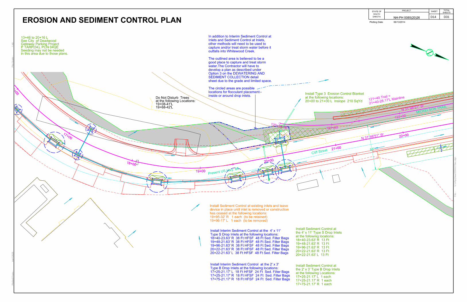
19+68-42’L19+08-41’Lat the following Locations:Do Not Disturb Trees
21+40-28.17
’L Mainline
121+40 Tra
il =
EROSION AND SEDIMENT CONTROL PLAN
13+46 to 20+16 LSee City of DeadwoodGateway Parking ProjectP TARP(04), PCN 04QESeeding may not be neededin this area due to those plans.
Install Interim Sediment Control at the 4’ x 11’
Type S Drop Inlets at the following locations:
18+40-23.63’ R 38 Ft HFSF 48 Ft Sed. Filter Bags
19+48-21.63’ R 38 Ft HFSF 48 Ft Sed. Filter Bags
19+96-21.63’ R 38 Ft HFSF 48 Ft Sed. Filter Bags
20+22-21.63’ R 38 Ft HFSF 48 Ft Sed. Filter Bags
20+22-21.63’ L 38 Ft HFSF 48 Ft Sed. Filter Bags
Install Interim Sediment Control at the 2’ x 3’
Type B Drop Inlets at the following locations:
17+25-21.17’ L 18 Ft HFSF 24 Ft Sed. Filter Bags
17+25-21.17’ R 18 Ft HFSF 24 Ft Sed. Filter Bags
17+75-21.17’ R 18 Ft HFSF 24 Ft Sed. Filter Bags
Install Sediment Control at
the 4’ x 11’ Type S Drop Inlets
at the following locations:
18+40-23.63’ R 13 Ft
19+48-21.63’ R 13 Ft
19+96-21.63’ R 13 Ft
20+22-21.63’ R 13 Ft
20+22-21.63’ L 13 Ft
Install Sediment Control at
the 2’ x 3’ Type B Drop Inlets
at the following Locations:
17+25-21.17’ L 1 each
17+25-21.17’ R 1 each
17+75-21.17’ R 1 each
20+00 to 21+00 L Inslope 210 SqYd
at the following locations:
Install Type 3 Erosion Control Blanket
Install Sediment Control at existing inlets and leave
device in place until inlet is removed or construction
has ceased at the following locations:
19+95-32’ R 1 each (to be retained)
19+96-17’ L 1 each (to be removed)
In addition to Interim Sediment Control at
Inlets and Sediment Control at Inlets,
other methods will need to be used to
capture and/or treat storm water before it
outfalls into Whitewood Creek.
The outlined area is believed to be a
good place to capture and treat storm
water.The Contractor will have to
develop a plan as described under
Option 3 on the DEWATERING AND
SEDIMENT COLLECTION detail
sheet due to the grade and limited space.
The circled areas are possible
locations for flocculant placement--
inside or around drop inlets.
D14 D31
DAKOTA
SOUTH
STATE OFPROJECT
SHEETSHEETS
TOTAL
NH-PH 0085(20)26
22+00
23+00
24+00
25+00
26+00
27+00
28+00
0+00
1+00
1+85
1+85
22+00
23+00
24+00
25+00
26+00
27+00
28+00
122+00
123+00
124+00125+00
126+00
127+00
128+00
213
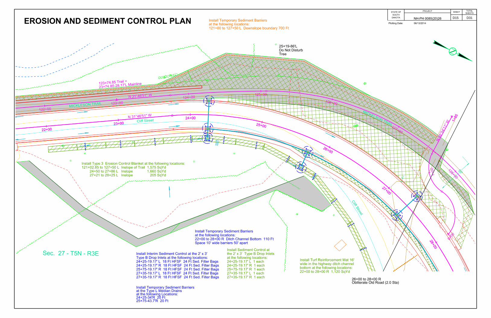
Sec. 27 - T5N - R3E
MICKLESON TRAIL
MICKELSON TRAIL
23+74.85-28.17’L Mainline123+74.85 Trail =
Tree
Do Not Disturb
25+19-86’L
Obliterate Old Road (2.0 Sta)26+00 to 28+00 R
Plotting Date: 06/13/2014
50’
EROSION AND SEDIMENT CONTROL PLAN
27+21 to 28+25 L Inslope 205 SqYd
24+50 to 27+86 L Inslope 1,660 SqYd
121+02.85 to 127+50 L Inslope of Trail 1,575 SqYd
Install Type 3 Erosion Control Blanket at the following locations:
27+35-19.17’ R 18 Ft HFSF 24 Ft Sed. Filter Bags
27+35-19.17’ L 18 Ft HFSF 24 Ft Sed. Filter Bags
25+75-19.17’ R 18 Ft HFSF 24 Ft Sed. Filter Bags
24+25-19.17’ R 18 Ft HFSF 24 Ft Sed. Filter Bags
24+25-19.17’ L 18 Ft HFSF 24 Ft Sed. Filter Bags
Type B Drop Inlets at the following locations:
Install Interim Sediment Control at the 2’ x 3’
25+75-43.7’R 20 Ft24+25-34’R 20 Ftat the following Locations:at the Type L Median DrainsInstall Temporary Sediment Barriers
27+35-19.17’ R 1 each
27+35-19.17’ L 1 each
25+75-19.17’ R 1 each
24+25-19.17’ R 1 each
24+25-19.17’ L 1 each
at the following locations:
the 2’ x 3’ Type B Drop Inlets
Install Sediment Control at
Space 10’ wide barriers 50’ apart
22+00 to 28+00 R Ditch Channel Bottom 110 Ft
at the following locations:
Install Temporary Sediment Barriers
121+00 to 127+50 L Downslope boundary 700 Ft
at the following locations:
Install Temporary Sediment Barriers
22+00 to 28+00 R 1,120 SqYd
bottom at the following locations:
wide in the highway ditch channel
Install Turf Reinforcement Mat 16’
Cliff S
treet
Cliff Street
D15 D31

DAKOTA
SOUTH
STATE OFPROJECT
SHEETSHEETS
TOTAL
NH-PH 0085(20)26
28+0
0
29+00
30+0031+00
32+0033+00
34+00
0+00
28+0
0
29+00
30+0031+00
32+0033+00
34+00
129+00
129+00
129+00
4676.94
STORM LINE
4676.94
STORM LINE15-INCH S PLASTIC
4677.90
STORM LINE
4677.90
STORM LINE15-INCH N PLASTIC
U:\rd\prj\la
wr0
555\0
28ec.d
gn
File -
Plotting Date: 06/13/2014
Plot Scale -
1:4
0Plotted Fro
m -
trpr1
3525
Cliff Street
MICKELSON TRAIL
Present US Hwy. 85
Retaining WallDo Not Disturb Rock33+25-67’R TO 34+32-47’R
outside work limitsAsphalt Pavement Retain Existing 28+00 to 33+04 R
Sec. 27 - T5N - R3E
EROSION AND SEDIMENT CONTROL PLAN
32+33-21.63’ R 13 Ft32+33-21.63’ L 13 Ftat the following locations:at the 4’ x 11’ Type S Drop Inlets Install Sediment Control
30+28-19.17’ R 1 each30+28-19.17’ L 1 each28+90-19.17’ R 1 eachat the following locations:the 2’ x 3’ Type B Drop InletsInstall Sediment Control at
32+33-21.63’ R 38 Ft HFSF 48 Ft Sed. Filter Bags32+33-21.63’ L 38 Ft HFSF 48 Ft Sed. Filter BagsType S Drop Inlets at the following locations:Install Interim Sediment Control at the 4’ x 11’
30+28-19.17’ R 18 Ft HFSF 24 Ft Sed. Filter Bags30+28-19.17’ L 18 Ft HFSF 24 Ft Sed. Filter Bags28+90-19.17’ R 18 Ft HFSF 24 Ft Sed. Filter BagsType B Drop Inlets at the following locations:Install Interim Sediment Control at the 2’ x 3’
32+16 to 35+25 R 570 SqYd
at the following locations:
in the highway ditch channel bottom
Install Turf Reinforcement Mat 16’ wide
32+33-38’ R 20 Ft 30+38-38’ R 20 Ft at the following locations:around the 3’ x 4’ Type C Drop Inlets Install Temporary Sediment Barriers
10’ Pieces spaced 50’ apart
32+50 to 35+00 R Ditch Channel 60 Ft
at the following locations:
Install Temporary Sediment Barriers
for sediment control at 28+00 R 90 FtInstall Temporary Sediment Barriers
32+10 to 32+55 L Trail Inslope 100 SqYd
32+10 to 32+55 L Inslope 240 SqYd
Install Type 3 Erosion Control Blanket at the following locations:
In addition to Interim Sediment Control at
Inlets and Sediment Control at Inlets,
other methods will need to be used to
capture and/or treat storm water before it
outfalls into Whitewood Creek.
The outlined area is believed to be a
good place to capture and treat storm
water.The Contractor will have to
develop a plan as described under
Option 3 on the DEWATERING AND
SEDIMENT COLLECTION detail
sheet due to the grade and limited space.
The circled areas are possible
locations for flocculant placement--
inside or around drop inlets.
D16 D31

DAKOTA
SOUTH
STATE OFPROJECT
SHEETSHEETS
TOTAL
NH-PH 0085(20)26
34+0
0
35+00
36+00
37+0038+00
39+00
40+00
34+0
0
35+00
36+00
37+0038+00
39+00
40+00
Present US Hwy. 85
U:\rd\prj\la
wr0
555\0
34ec.d
gn
File -
Plotting Date: 06/13/2014
Plot Scale -
1:4
0Plotted Fro
m -
trpr1
3525
MICKELS
ON TRAI
L
MICKELSON TRAIL
Sign
Do Not Disturb
36+67-29’L
concrete base.
Columns, and raised
Do Not Disturb Canopy,
37+28 to 37+53 L
Do Not Disturb Walls
38+39 L
Bushes
Do Not Disturb
39+80 to 39+91 L
Tim
m Lane
EROSION AND SEDIMENT CONTROL PLAN
39+00-19.17’ R 1 each
39+00-19.17’ L 1 each
at the following locations:
the 2’ x 3’ Type B Drop Inlets
Install Sediment Control at
39+00-19.17’ R 18 Ft HFSF 24 Ft Sed. Filter Bag
39+00-19.17’ L 18 Ft HFSF 24 Ft Sed. Filter Bag
Type B Drop Inlets at the following locations:
Install Interim Sediment Control at the 2’ x 3’
38+98-30.5’R 20 Ft
3’ X 4’ Type C Drop Inlet at the following location:
Install Temporary Sediment Barriers around the
37+50 R 10 Ft
37+00 R 10 Ft
at the following locations:
in the hightway ditch channel bottom
Install Temporary Sediment Barriers
38+76 to 39+22 R 50 SqYd
36+50 to 37+80 R 240 SqYd
16’ wide at the following locations:
the highway ditch channel bottom
Install Turf Reinforcement Mat in
Sec. 27 - T5N - R3E
Cliff Street
D17 D31

DAKOTA
SOUTH
STATE OFPROJECT
SHEETSHEETS
TOTAL
NH-PH 0085(20)26
40+00
41+00
42+00
43+00
44+00
45+00
46+0
0
40+00
41+00
42+00
43+00
44+00
45+00
46+0
0
+
+
+
4637.85
STORM LINESE RCP 4637.88
STORM LINE
4638.81
STORM LINENW RCP 4643.48
DROP INLET0 0 0 LOTS OF SEDIMENT IN BOTTOM OF STRUCTURE.
4643.48
DROP INLET
4643.48
DROP INLET
4651.64
CORRUGATED METAL PIPE
4651.64
STORM LINE
4651.64
STORM LINE
4652.12
STORM LINESE CMP
4652.12
STORM LINESE CMP
4652.32
STORM LINE
4653.03
STORM LINE
4655.69
STORM LINEDRAWN IN QL D
4656.94
DROP INLET
4657.03
DROP INLET
Present US Hwy. 85
U:\rd\prj\la
wr0
555\0
40ec.d
gn
File -
Plotting Date: 06/13/2014
Plot Scale -
1:4
0Plotted Fro
m -
trpr1
3525
WHIT
EW
OO
D C
RE
EK
Tim
m Lane
Sta 41+97.54
MIC
KELSO
N T
RAI
L
Begin Mill & OverlayEnd Grading
Do Not Disturb Sign42+09 R
(4.5 CY)Protection Gabions Install Bank and Channel42+33 R
Mickelson Trail SurfacingDo Not Disturb 43+68 to 45+30 L
(See Section E)Reconstruct Retaining Wall42+25.91 to 42+33.48 R
EROSION AND SEDIMENT CONTROL PLAN
44+13 to 45+00 L Backslope 150 SqYd
Install Type 3 Erosion Control Blanket at the following locations:
40+20 to 40+50 R 55 SqYd
16’ wide at the following locations:
the highway ditch channel bottom
Install Turf Reinforcement Mat in
40+41-30’R 20 Ftat the following location:around the 3’ X 4’ Type C Drop InletInstall Temporary Sediment Barriers
42+04.5-19.67’ R 1 each40+41-19.17’ R 1 eachat the following locations:the 2’ X 3’ Type B Drop InletsInstall Sediment Control at
42+04.5-19.67’ R 18 Ft HFSF 24 Ft Sed. Filter Bags40+41-19.17’ R 18 Ft HFSF 24 Ft Sed. Filter BagsType B Drop Inlets at the following locations:Install Interim Sediment Control at the 2’ X 3’
42+05-20’ R 1 each (replacing)42+05-19’L 1 each (retaining)or grading has ceased:place until the inlet is removedexisting inlets and leave inInstall Sediment Control at
45+39 R 1 each (retaining)45+39 L 1 each (retaining)or grading has ceased:place until the inlet is removedexisting inlets and leave inInstall Sediment Control at
Cliff Street
DEADWOOD
GULCH’S
OF FUN
In addition to Interim Sediment Control at
Inlets and Sediment Control at Inlets,
other methods will need to be used to
capture and/or treat storm water before it
outfalls into Whitewood Creek.
The outlined area is believed to be a
good place to capture and treat storm
water.The Contractor will have to
develop a plan as described under
Option 3 on the DEWATERING AND
SEDIMENT COLLECTION detail
sheet due to the grade and limited space.
The circled areas are possible
locations for flocculant placement--
inside or around drop inlets.
D18 D31

DAKOTA
SOUTH
STATE OFPROJECT
SHEETSHEETS
TOTAL
NH-PH 0085(20)26
46+00
47+00
48+00
49+00 50+00
51+00
52+0
0
46+00
47+00
48+00
49+00 50+00
51+00
52+0
0 4619.79
CORRUGATED METAL PIPE
4619.79
CORRUGATED METAL PIPE
4623.61
CORRUGATED METAL PIPE
4623.61
CORRUGATED METAL PIPE
4624.17
STORM LINE
4624.17
STORM LINE
4625.07
CORRUGATED METAL PIPE
4625.09
STORM LINE
4625.15
STORM LINE
4625.15
STORM LINE
4625.50
STORM LINEDRAWN IN QL D
4625.70
STORM LINE
4626.00
STORM LINEDRAWN IN QL D
4626.91
CORRUGATED METAL PIPE
4627.00
STORM LINEDRAWN IN QL D
4627.00
STORM LINEDRAWN IN QL D
4627.42
DROP INLET
4627.85
STORM LINE
4627.85
STORM LINE
4627.94
STORM LINE
4628.22
STORM LINE
4628.86
DROP INLET
4629.54
STORM LINE
4629.66
DROP INLET
4629.74
DROP INLET
111
4630.342
4631.79
DROP INLET
4631.80
DROP INLET0 0 0 OF SEDIMENT IN BOTTOM OF STRUCTURE.
4631.80
DROP INLET0 0 0 OF SEDIMENT IN BOTTOM OF STRUCTURE.
4655.69
STORM LINEDRAWN IN QL D
4655.69
STORM LINEDRAWN IN QL D
Cliff StreetPresent US Hwy. 85
U:\rd\prj\la
wr0
555\0
46ec.d
gn
File -
Plotting Date: 06/13/2014
Plot Scale -
1:4
0Plotted Fro
m -
trpr1
3525
WHIT
EW
OO
D C
RE
EK
MICKELSON TRAIL
EROSION AND SEDIMENT CONTROL PLAN
50+44 R 1 each (retaining)50+44 L 1 each (retaining)47+89 R 1 each (retaining)47+89 L 1 each (retaining)or grading has ceased:place until the inlet is removedexisting inlets and leave inInstall Sediment Control at
D19 D31

DAKOTA
SOUTH
STATE OFPROJECT
SHEETSHEETS
TOTAL
NH-PH 0085(20)26
52+00
53+00
54+00
55+00
56+00
57+0058+00
52+00
53+00
54+00
55+00
56+00
57+0058+00
4623.05 CORRUGATED METAL PIPE
4623.05 CORRUGATED METAL PIPE
4623.31 CORRUGATED METAL PIPE
4623.31 CORRUGATED METAL PIPE
4624.17 STORM LINEOHTVCB
4624.17 STORM LINEOHTVCB
4624.19 STORM LINESE RCP
4624.19 STORM LINE24-INCH W RCP
4624.27 CORRUGATED METAL PIPE0 PIPE DAMAGED.
4624.27 CORRUGATED METAL PIPE
4624.29 CORRUGATED METAL PIPE0 PIPE DAMAGED.
4624.29 CORRUGATED METAL PIPE
4624.44 STORM LINE
4624.59 STORM LINE
4624.64 STORM LINE
4624.96 STORM LINE
4625.11 STORM LINE
4625.25 STORM LINE
4625.59 STORM LINE
4625.87 STORM LINESW RCP
4625.87 STORM LINESW RCP
4626.91 CORRUGATED METAL PIPE
4627.42 DROP INLET
4628.32 DROP INLET
4628.39 STORM MANHOLE
4628.44 DROP INLET
4628.48 DROP INLET
4628.49 STORM MANHOLE
4628.51 DROP INLET
4628.86 DROP INLET
U:\rd\prj\la
wr0
555\0
52ec.d
gn
File -
Plotting Date: 06/13/2014
Plot Scale -
1:4
0Plotted Fro
m -
trpr1
3525
Elim Ent.57+70 R
Sta. 54+44.00
Begin GradingEnd Mill & Overlay
Steel PostsColumns, Handrails, andDo Not Disturb Canopy,53+06 to 53+37 L
Brick ColumnsDo Not Disturb 56+89-31’R & 57+04-31’R
Do Not Disturb 4 Trees56+27-34’R to 56+76-36’R
(clearing)above new sidewalkTrim Branches Retain Tree and53+80-38’R
ShedDo Not Disturb 57+83-34’R
and Curb & GutterDo Not Disturb Sidewalk53+64-67’L to 55+14-60’L
(See Section E)Install Retaining Wall53+44.22 to 56+65 L
EROSION AND SEDIMENT CONTROL PLAN
54+95-41.3’R 1 each (retaining)54+66-38’R 1 each (removing)54+39-19’R 1 each (retaining)54+39-19’L 1 each (retaining)device) at the following locations:assembly is in place (then replace the is removed OR a new frame and grate inlets and leave in place until the inlet Install Sediment Control at existing
54+95-41.3’R 22 Ft HFSF 32 Ft Sed. Filter Bags54+39-19’R 22 Ft HFSF 32 Ft Sed. Filter Bags54+39-19’L 22 Ft HFSF 32 Ft Sed. Filter Bagsbe installed at the following locations:leave in place until the new frame and grate can after the frame and grate has been removed and Install Interim Sediment Control at existing inlets
56+68-35’R 20 Ft
at the following location:
around the 3’x4’ Type C Drop Inlet
Install Temporary Sediment Barriers
56+25-19.17’R 1 each
55+00.5-21.4’R 1 each
at the following loactions:
at 3’x4’ Drop Inlets
Install Sediment Control
56+25-19.17’R 22 Ft HFSF 32 Ft Sed. Filter Bags
55+00.5-21.4’R 22 Ft HFSF 32 Ft Sed. Filter Bags
Drop Inlets at the following loactions:
Install Interim Sediment Control at 3’x4’
57+56-19.17’ R 1 each
56+68-19.17’ R 1 each
56+19.5-19.17’ L 1 each
54+63.9-49.5’ R 1 each
53+42.5-29.67’L 1 each
at the following locations:
2’ x 3’ Type B Drop Inlets
Install Sediment Control at the 57+56-19.17’ R 18 Ft HFSF 24 Ft Sed. Filter Bags
56+68-19.17’ R 18 Ft HFSF 24 Ft Sed. Filter Bags
56+19.5-19.17’ L 18 Ft HFSF 24 Ft Sed. Filter Bags
54+63.9-49.5’ R 18 Ft HFSF 24 Ft Sed. Filter Bags
53+42.5-29.67’L 18 Ft HFSF 24 Ft Sed. Filter Bags
at the following locations:
Install Sediment Control at the 2’ x 3’ Type B Drop Inlets
Cliff Street
In addition to Interim Sediment Control at
Inlets and Sediment Control at Inlets,
other methods will need to be used to
capture and/or treat storm water before it
outfalls into Whitewood Creek.
The outlined area is believed to be a
good place to capture and treat storm water.
This area may be sufficient for all
options on the DEWATERING AND
SEDIMENT COLLECTION detail sheet.
The circled areas are possible
locations for flocculant placement--
inside or around drop inlets.
D20 D31

DAKOTA
SOUTH
STATE OFPROJECT
SHEETSHEETS
TOTAL
NH-PH 0085(20)26
58+00
59+0
0
60+0
0
61+00 62+00
63+00
64+00
58+00
59+0
0
60+0
0
61+00 62+00
63+00
64+00
113
4615.043
4621.86
CORRUGATED METAL PIPE 4621.86
CORRUGATED METAL PIPE
4622.23
CORRUGATED METAL PIPE 4622.23
CORRUGATED METAL PIPE
4623.05
CORRUGATED METAL PIPE 4623.05
CORRUGATED METAL PIPE
4623.31
CORRUGATED METAL PIPE 4623.31
CORRUGATED METAL PIPE
112
4627.912
ORIGINAL TOWN OF DEADWOOD
U:\rd\prj\la
wr0
555\0
58ec.d
gn
File -
Plotting Date: 06/13/2014
Plot Scale -
1:4
0Plotted Fro
m -
trpr1
3525
66’
Planter & SignDo Not Disturb62+48 L
Do Not Disturb tree59+30-34’R
Steel PostDo Not Disturb 60+72-81’R
Bushes, & LandscapingDo Not Disturb Sign,59+17 L
Calam
ity Lane
(See Section E)Install Retaining Wall59+72.4 to 59+82.4 L
(See Section E)Install Retaining Wall60+30 to 60+70 L
EROSION AND SEDIMENT CONTROL PLAN
10’ Pieces spaced 50’ apart
61+00 to 64+00 R Ditch Channel 60 Ft
at the following locations:
Install Temporary Sediment Barriers
63+50-19.17’ R 18 Ft HFSF 24 Ft Sed. Filter Bags
63+50-19.17’ L 18 Ft HFSF 24 Ft Sed. Filter Bags
62+30-21.17’R 18 Ft HFSF 24 Ft Sed. Filter Bags
61+25-21.17’ R 18 Ft HFSF 24 Ft Sed. Filter Bags
61+25-21.17’ L 18 Ft HFSF 24 Ft Sed. Filter Bags
59+25-19.17’ R 18 Ft HFSF 24 Ft Sed. Filter Bags
58+85.22-45.5’ R 18 Ft HFSF 24 Ft Sed. Filter Bags
58+62.63-40.42’ R 18 Ft HFSF 24 Ft Sed. Filter Bags
58+20-19.17’ R 18 Ft HFSF 24 Ft Sed. Filter Bags
58+20-19.17’ L 18 Ft HFSF 24 Ft Sed. Filter Bags
Type B Drop Inlets at the following locations:
Install Interim Sediment Control at the 2’ x 3’
63+50-19.17’ R 1 each
63+50-19.17’ L 1 each
62+30-21.17’R 1 each
61+25-21.17’ R 1 each
61+25-21.17’ L 1 each
59+25-19.17’ R 1 each
58+85.22-45.5’ R 1 each
58+62.63-40.42’ R 1 each
58+20-19.17’ R 1 each
58+20-19.17’ L 1 each
at the following locations:
the 2’ x 3’ Type B Drop Inlets
Install Sediment Control at
63+50-34.5’R 20 Ft62+30-33’R 20 Ftat the following locations:around Type L Median DrainsInstall Temporary Sediment Barriers
60+50 to 64+38 R 670 SqYd
16’ wide at the following locations:
the highway ditch channel bottom
Install Turf Reinforcement Mat in
Charles Street
D21 D31

DAKOTA
SOUTH
STATE OFPROJECT
SHEETSHEETS
TOTAL
NH-PH 0085(20)26
64+0
0
65+0
0
66+00
67+00
68+00
69+00
70+00
64+0
0
65+0
0
66+00
67+00
68+00
69+00
70+00
R
12
4596.56
MON
11
4
4596.565
4596.86
CORRUGATED METAL PIPE
4596.86
CORRUGATED METAL PIPE
4596.86
CORRUGATED METAL PIPE
4596.95
CORRUGATED METAL PIPE
4598.45
CORRUGATED METAL PIPE
0 PIPE IS UNDER BRIDGE. COULD NOT GET ACCURATE DEP
WHI
TEW
OOD CREEK
U:\rd\prj\la
wr0
555\0
64ec.d
gn
File -
Plotting Date: 06/13/2014
Plot Scale -
1:4
0Plotted Fro
m -
trpr1
3525
Do Not Disturb Sign65+03 L
Protection Gabions (4.5 CY)Install Bank and Channel65+45 L
Wall & FenceDo Not Disturb69+37 L
Bushes & TreesDo Not Disturb69+79 to 70+36 L
Do Not Disturb Canopy66+78 to 67+17 R
68+11-31’R67+99-32’Rat the following locations:Do Not Disturb Trees
69+60 to 69+85 R69+36 to 69+60 Rat the following locations:Do Not Disturb Walls
60’
TOWN OF DEADWOODORIGINAL
(See Section E)Install Handrail 65+47 to 65+61 L
(See Section E)Install Retaining Wall67+48 to 67+56 L
(See Section E)Reconstruct Retaining Wall65+44 L
(See Section E)Install Concrete Barrier66+03.36 to 67+55.41 L
EROSION AND SEDIMENT CONTROL PLAN
64+25-33’R 20 Ftat the following location:around the Type L Median DrainInstall Temporary Sediment Barriers
69+90 -21.63’R 38 Ft HFSF 48 Ft Sed. Filter BagsType S Drop Inlet at the following location:Install Interim Sediment Control at the 4’x11’
69+90 -21.63’R 13 FtType S Drop Inlet at the following location:Install Sediment Control at the 4’x11’
69+90 -19.17’ L 18 Ft HFSF 24 Ft Sed. Filter Bags68+82 -19.89’ R 18 Ft HFSF 24 Ft Sed. Filter Bags68+04 -21.17’ R 18 Ft HFSF 24 Ft Sed. Filter Bags68+04 -21.17’ L 18 Ft HFSF 24 Ft Sed. Filter Bags67+23 -19.17’ R 18 Ft HFSF 24 Ft Sed. Filter Bags65+37 -19.17’ R 18 Ft HFSF 24 Ft Sed. Filter Bags65+37 -19.17’ L 18 Ft HFSF 24 Ft Sed. Filter Bags64+25-19.17’R 18 Ft HFSF 24 Ft Sed. Filter BagsType B Drop Inlets at the following locations:Install Interim Sediment Control at the 2’ x 3’
69+90 -19.17’ L 1 each68+82 -19.89’ R 1 each68+04 -21.17’ R 1 each68+04 -21.17’ L 1 each67+23 -19.17’ R 1 each65+37 -19.17’ R 1 each65+37 -19.17’ L 1 each64+25-19.17’R 1 eachat the following locations:2’ x 3’ Type B Drop Inlets Install Sediment Control at the
65+57 R 20 Ftat the following location:place until the inlet is removedaround the existing inlet and leave inInstall Temporary Sediment Barriers
In addition to Interim Sediment Control at
Inlets and Sediment Control at Inlets,
other methods will need to be used to
capture and/or treat storm water before it
outfalls into Whitewood Creek.
The outlined area is believed to be a
good place to capture and treat storm
water.The Contractor will have to
develop a plan as described under
Option 3 on the DEWATERING AND
SEDIMENT COLLECTION detail
sheet due to the grade and limited space.
The circled areas are possible
locations for flocculant placement--
inside or around drop inlets.
D22 D31
DAKOTA
SOUTH
STATE OFPROJECT
SHEETSHEETS
TOTAL
NH-PH 0085(20)26
70+0071+00
72+0073+00 74+00
75+0076+00
70+0071+00
72+0073+00 74+00
75+0076+00
STORM LINE
24-INCH N RCP
STORM LINE
STORM LINE
4582.6
3
DROP INLET
0 0 0 ROUND STROM DRAIN INLET.
4585.9
6
DROP INLET
Pro
p. Line
Charles Street
Present US Hwy. 85
ROTARY
PARK
U:\rd\prj\la
wr0
555\0
70ec.d
gn
File -
Plotting Date: 06/13/2014
Plot Scale -
1:4
0Plotted Fro
m -
trpr1
3525
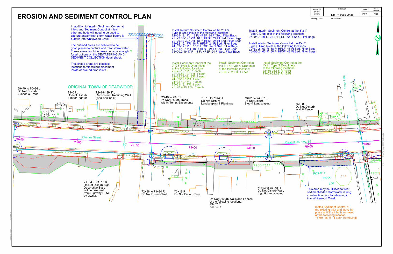
(See Section E)Reconstruct Retaining Wall72+18-189.1’ L
ORIGINAL TOWN OF DEADWOOD
Bushes & TreesDo Not Disturb69+79 to 70+36 L
Timber PlanterDo Not Disturb71+63 L
Within Temp. EasementsDo Not Disturb Trees72+46 to 73+01 L
Landscaping & PlantingsDo Not Disturb 73+18 to 73+40 L
Step & Landscaping Do Not Disturb 73+81 to 74+07 L
Wall & FenceDo Not Disturb 75+20 L
Do Not Disturb Tree73+19 R
Sign & LandscapingDo Not Disturb Wall,74+03 to 75+58 R
LOT
Do Not Disturb Wall72+88 to 73+24 R
74+84 R73+37 Rat the following locations:Do Not Disturb Walls and Fences
60’
by Owner.from Highway ROW will be removed Decorative BaseDo Not Disturb Sign.71+04 to 71+16 R
EROSION AND SEDIMENT CONTROL PLAN
75+95-18’ R 1 each (removing)at the following location:place until the inlet is removedthe existing inlet and leave inInstall Sediment Control at
75+90.2-19.17’R 1 each75+61-19.17’R 1 each74+32-19.17’ L 1 each74+32-19.17’R 1 each72+29.32-32.12’R 1 each72+29.50-19.17’R 1 each72+25-19.17’L 1 eachat the following locations:2’ X 3’ Type B Drop InletsInstall Sediment Control at the
75+90.2-19.17’R 18 Ft HFSF 24 Ft Sed. Filter Bags75+61-19.17’R 18 Ft HFSF 24 Ft Sed. Filter Bags74+32-19.17’ L 18 Ft HFSF 24 Ft Sed. Filter Bags74+32-19.17’R 18 Ft HFSF 24 Ft Sed. Filter Bags72+29.32-32.12’R 18 Ft HFSF 24 Ft Sed. Filter Bags72+29.50-19.17’R 18 Ft HFSF 24 Ft Sed. Filter Bags72+25-19.17’L 18 Ft HFSF 24 Ft Sed. Filter BagsType B Drop Inlets at the following locations:Install Interim Sediment Control at the 2’ X 3’
75+95.7 -20’ R 1 each
at the following location:
the 3’ x 4’ Type C Drop Inlet
Install Sediment Control at
75+95.7 -20’ R 22 Ft HFSF 32 Ft Sed. Filter Bags
Type C Drop Inlet at the following location:
Install Interim Sediment Control at the 3’ x 4’
73+53-21.63’ R 38 Ft HFSF 48 Ft Sed. Filter Bags72+60-21.63’ R 38 Ft HFSF 48 Ft Sed. Filter BagsType S Drop Inlets at the following locations:Install Interim Sediment Control at the 4’x11’
73+53-21.63’ R 13 Ft72+60-21.63’ R 13 Ftat the following locations:4’x11’ Type S Drop Inlets Install Sediment Control at the
This area may be utilized to treat
sediment-laden stormwater during
construction prior to releasing it
into Whitewood Creek.
In addition to Interim Sediment Control at
Inlets and Sediment Control at Inlets,
other methods will need to be used to
capture and/or treat storm water before it
outfalls into Whitewood Creek.
The outlined areas are believed to be
good places to capture and treat storm water.
These areas combined may be large enough
for all options on the DEWATERING AND
SEDIMENT COLLECTION detail sheet.
The circled areas are possible
locations for flocculant placement--
inside or around drop inlets..
D23 D31

DAKOTA
SOUTH
STATE OFPROJECT
SHEETSHEETS
TOTAL
NH-PH 0085(20)26
76+00
77+00
78+00
79+00
80+0081+0
0
82+0
0
76+00
77+00
78+00
79+00
80+0081+0
0
82+0
0
4568.86
STORM LINESE RCP 4568.86
STORM LINENW RCP
4568.95
STORM LINE
4568.95
STORM LINESE RCP
4570.01
STORM LINENW CMP
4570.01
STORM LINENW CMP
4570.26
STORM LINESE CMP
4571.60
STORM LINE
4571.94
STORM LINESE RCP 4572.01
STORM LINESW VCP
4572.01
STORM LINESW VCP
4573.66
DROP INLET
4574.36
DROP INLET0 0 0 HOLE IN RCP PIPE FOR WATER TO ENTER AND DRAI
4575.97
STORM MANHOLE
4577.67
STORM LINE24-INCH N RCP
4577.68
STORM LINE
4582.63
DROP INLET0 0 0 ROUND STROM DRAIN INLET.
ORIGINAL TOWN OF DEADWOOD
Charles
Street
U:\rd\prj\la
wr0
555\0
76ec.d
gn
File -
Plotting Date: 06/13/2014
Plot Scale -
1:4
0Plotted Fro
m -
trpr1
3525
(See Section E)Reconstruct Retaining Wall80+09-148’ L
ORIGINAL TOWN OF DEADWOOD
Present US Hwy. 85
& LandscapingDo Not Disturb Sign76+00-32’L
& LandscapingDo Not Disturb Trees76+66 to 76+74 L
76+68 R76+57 R76+00 to 76+54 R76+00 Rat the following locations:Do Not Disturb Walls
BushesDo Not Disturb77+55 R
SignDo Not Disturb78+23-33’R
Remove and Reset Fence80+10-124’L to 80+33-130’L
80+78 to 80+93--38’L to 52’L80+64-120’L80+02-134’Lat the following locations:Trees & BushesDo Not Disturb
TreeDo Not Disturb79+22-29’ L
and FlagpoleLights, Lightpole,Do Not Disturb Sign,80+80 to 81+09 R
EROSION AND SEDIMENT CONTROL PLAN
80+51-21.17’ R 18 Ft HFSF 24 Ft Sed. Filter Bags79+21-19.17’ L 18 Ft HFSF 24 Ft Sed. Filter Bags79+21-19-17’ R 18 Ft HFSF 24 Ft Sed. Filter Bags77+65-19.17’ R 18 Ft HFSF 24 Ft Sed. Filter BagsType B Drop Inlets at the following locations:Install Interim Sediment Control at the 2’ x 3’
80+51-21.17’ R 1 each79+21-19.17’ L 1 each79+21-19-17’ R 1 each77+65-19.17’ R 1 eachat the following locations:2’ x 3’ Type B Drop Inlets Install Sediment Control at the
81+29-21.15’L 30 Ft HFSF 32 Sed. Filter Bags80+65-21.17’L 30 Ft HFSF 32 Sed. Filter BagsType B Drop Inlets at the following locations: Install Interim Sediment Control at the 5.5’ X 5.5’
81+29-21.15’L 1 each80+65-21.17’L 1 eachat the following locations: 5.5’ X 5.5’ Type B Drop Inlets Install Sediment Control at the
81+34-22.27’R 38 Ft HFSF 48 Ft Sed Filter BagsType S Drop Inlet at the following location: Install Interim Sediment Control at the 4’ X 11’
81+34-22.27’R 13 Ftat the following location: 4’ X 11’ Type S Drop Inlet Install Sediment Control at the
81+63-19.17’R 24 Ft HFSF 32 Ft Sed. Filter Bags
Type B Drop Inlet at the following locations:
Install Interim Sediment Control at the 4’ X 4’
81+63-19.17’R 1 each
at the following locations:
4’ X 4’ Type B Drop Inlet
Install Sediment Control at the
Install Sediment Control at existing inlets and leave
device in place until inlet is removed or construction
has ceased at the following locations:
81+23-24’L 1 each (to be removed)
81+64-15’R 1 each (to be removed)
In addition to Interim Sediment Control at
Inlets and Sediment Control at Inlets,
other methods will need to be used to
capture and/or treat storm water before it
outfalls into Whitewood Creek.
The circled areas are possible
locations for flocculant placement--
inside or around drop inlets.
The outlined areas are believed to be
good places to capture and treat storm water.
These areas combined may be large enough
for all options on the DEWATERING AND
SEDIMENT COLLECTION detail sheet.
D24 D31

82+00
83+00
84+00
85+00
86+00 87+00
88+0
0
82+00
83+00
84+00
85+00
86+00 87+00
88+0
0
DAKOTA
SOUTH
STATE OFPROJECT
SHEETSHEETS
TOTAL
NH-PH 0085(20)26
4558.41
STORM LINE
4558.41
STORM LINE
4560.23
STORM LINESE RCP
4560.23
STORM LINESE RCP
4560.37
STORM LINE
4560.37
STORM LINE
4560.41
STORM LINE 4560.46
STORM LINE
4560.46
STORM LINE
4562.60
STORM LINE
4563.74
DROP INLET
4564.71
STORM LINE
4565.40
STORM LINENW RCP
4566.00
DROP INLET
117
4566.613
4566.76
STORM MANHOLE
4566.81
STORM LINE
4566.81
STORM LINE
4566.83
DROP INLET
4568.71
DROP INLET
4569.08
DROP INLET
4569.30
DROP INLET
116
4572.321
Charles Street
Elim Ent.
84+86 R
& Air ConditionerDo Not Disturb Building82+24 to 83+04-L
Handrails outside of Worklimits.Rocks, Landscaping, and 2Do Not Disturb Trees, Shrubs,87+40 to 89+42 L
by othersSign to be moved87+41-22’L
Elim Ent.87+16 L
SignDo Not Disturb83+68-33’R
Large RocksDo Not Disturb86+29 R
(Clearing)above New SidewalkTrim BranchesRetain Bushes and 84+93 to 85+33 R
Sign & PlanterDo Not Disturb85+87-30’R
Retain Sidewalk86+29-30’R to 87+06-83’R
Divisio
n Street
Harrison Street
EROSION AND SEDIMENT CONTROL PLAN
87+56-40’R 1 each86+69-43’R 1 each at the following locations:place until the inlet is removedexisting inlets and leave inInstall Sediment Control at
87+18-21.17’ L 18 Ft HFSF 24 Ft Sed. Filter Bags
87+15.69-46.86’L 18 Ft HFSF 24 Ft Sed. Filter Bags
86+99.5-43.77’R 18 Ft HFSF 24 Ft Sed. Filter Bags
86+77.5-21.17’ R 18 Ft HFSF 24 Ft Sed. Filter Bags
85+91-21.17’ L 18 Ft HFSF 24 Ft Sed. Filter Bags
84+25-19.17’ R 18 Ft HFSF 24 Ft Sed. Filter Bags
83+60-19.17’ L 18 Ft HFSF 24 Ft Sed. Filter Bags
Type B Drop Inlets at the following locations:
Install Interim Sediment Control at the 2’ x 3’
87+18-21.17’ L 1 each
87+15.69-46.86’L 1 each
86+99.5-43.77’R 1 each
86+77.5-21.17’ R 1 each
85+91-21.17’ L 1 each
84+25-19.17’ R 1 each
83+60-19.17’ L 1 each
at the following locations:
2’ x 3’ Type B Drop Inlets
Install Sediment Control at the
85+91-23.63’ R 38 Ft HFSF 48 Ft Sed. Filter Bags
83+60-21.63’ R 38 Ft HFSF 48 Ft Sed. Filter Bags
Type S Drop Inlets at the following locations:
Install Interim Sediment Control at the 4’x11’
85+91-23.63’ R 13 Ft
83+60-21.63’ R 13 Ft
at the following locations:
4’x11’ Type S Drop Inlets
Install Sediment Control at the
87+26.3-22.9’R 22 Ft HFSF 32 Ft Sed. Filter Bags
Type C Drop Inlet at the following location:
Install Interim Sediment Control at the 3’x4’
87+26.3-22.9’R 1 each
at the following location:
3’x4’ Type C Drop Inlet
Install Sediment Control at the
87+70-21.5’R 22 Ft HFSF 32 Ft Sed. Filter Bags
Type B Drop Inlet at the following location:
Install Interim Sediment Control at the 4’X3’
87+70-21.5’R 1 each
at the following location:
4’X3’ Type B Drop Inlet
Install Sediment Control at the
U:\rd\prj\la
wr0
555\0
82ec.d
gn
File -
Plotting Date: 06/13/2014
Plot Scale -
1:4
0Plotted Fro
m -
trpr1
3525
D25 D31

DAKOTA
SOUTH
STATE OFPROJECT
SHEETSHEETS
TOTAL
NH-PH 0085(20)26
56’88+0089+00 90+00 91+00 92+00 93+00 94+00
88+0089+00 90+00 91+00 92+00 93+00 94+00
++
++
++ +
2+00
3+00
4+00
+ +
++
+++ +
+
Lot 2
RECREATION
++
++
+
+ ++
4550.66 STORM LINENE RCP
4551.43 STORM LINESW RCP
4552.44 STORM LINE
4552.44 STORM LINE
4552.44 STORM LINE
4553.13 STORM LINE
4553.13 STORM LINE
4553.26 STORM LINE
4553.26 STORM LINE
4553.26 STORM LINE
4553.44 STORM LINE
4553.44 STORM LINE
4554.77 STORM LINE
4554.77 STORM LINE
4554.88
DROP INLET
4555.06
DROP INLET
118
4556.433
4557.20
DROP INLET
4557.27 STORM LINE
4557.27 STORM LINE
4557.33
DROP INLET
4557.34
DROP INLET
4557.49
DROP INLET
4557.56 STORM LINE
4557.56 STORM LINE
4558.41 STORM LINE
4558.41 STORM LINE
4561.95
DROP INLET
4562.15
DROP INLET
4563.74
DROP INLET
Vacate
d P
ortio
n of
Ce
metery Street
Ce
metery Street
U:\rd\prj\la
wr0
555\0
88ec.d
gn
File -
Plotting Date: 06/13/2014
Plot Scale -
1:4
0Plotted Fro
m -
trpr1
3525
56’
Do Not Disturb Tree
88+83 R
88+30 R88+04 to 88+29 Rat the following locations:Do Not Disturb Historical Walls
Concrete Pads outside of WorklimitsLandscaping, Picnic Tables, andDo Not Disturb Trees, Bushes,92+80 to 94+69 R
Elim Ent.
89+80-40’L
=92+56 Mainline3+00 XR92
21.7
5’
8.2
5’
XR
92
EROSION AND SEDIMENT CONTROL PLAN
93+82-20’L 1 each (retaining)93+81-19’R 1 each (removing)92+69-43’R 1 each (removing)92+37-19’R 1 each (removing)92+34-19’L 1 each (removing)89+96-20’L 1 each (removing)89+91-18’R 1 each (removing)88+22-20’R 1 each (removing)or grading has ceased:place until the inlet is removedexisting inlets and leave inInstall Sediment Control at
92+53-18’R 36 Ft HFSF 48 Ft Sed. Filter BagsJunction Box at the following location:Install Interim Sediment Control at the 7’x7’
93+81.09-26.97’R 18 Ft HFSF 24 Ft Sed. Filter Bags92+41.23-48.1’ R 18 Ft HFSF 24 Ft Sed. Filter Bags92+13.5-19.17’ L 18 Ft HFSF 24 Ft Sed. Filter Bags 90+00-19.17’ L 18 Ft HFSF 24 Ft Sed. Filter Bags89+80.48-38.5’L 18 Ft HFSF 24 Ft Sed. Filter Bags89+43.17-38.5’L 18 Ft HFSF 24 Ft Sed. Filter Bags89+23-19.17’ L 18 Ft HFSF 24 Ft Sed. Filter BagsType B Drop Inlets at the following locations:Install Interim Sediment Control at the 2’ x 3’
92+13.5-26.08’ R 22 Ft HFSF 32 Ft Sed. Filter Bags90+00-19.17’ R 22 Ft HFSF 32 Ft Sed. Filter Bags88+38-19.60’ R 22 Ft HFSF 32 Ft Sed. Filter BagsType B Drop Inlets at the following locations:Install Interim Sediment Control at the 4’x3’
92+69.09-48.1’R 25 Ft HFSF 32 Ft Sed. Filter BagsType B Drop Inlet at the following location:Install Interim Sediment Control at the 5.5’x3’
93+81.09-26.97’R 1 each92+41.23-48.1’ R 1 each92+13.5-19.17’ L 1 each90+00-19.17’ L 1 each89+80.48-38.5’L 1 each89+43.17-38.5’L 1 each89+23-19.17’ L 1 eachat the following locations:2’ x 3’ Type B Drop Inlets InstallSediment Control at the
92+69.09-48.1’R 1 eachat the following location:the 5.5’x3’ Type B Drop Inlet Install Sediment Control at
92+13.5-26.08’ R 1 each90+00-19.17’ R 1 each88+38-19.60’ R 1 eachat the following locations:the 4’x3’ Type B Drop Inlets Install Sediment Control at
Handrails outside of Worklimits.Rocks, Landscaping, and 2Do Not Disturb Trees, Shrubs,87+40 to 89+42 L
D26 D31

DAKOTA
SOUTH
STATE OFPROJECT
SHEETSHEETS
TOTAL
NH-PH 0085(20)26
92+00
93+00
92+00
93+00
0+00 1+00 2+00 3+00 4+00
4549.85
STORM LINE
7290
4549.
85
4550.00
STORM LINE
4550.00
STORM LINE
4550.13
STORM LINE
4550.13
STORM LINE
4552.44
STORM LINE
4552.44
STORM LINE
4553.13
STORM LINE
4553.13
STORM LINE
4553.26
STORM LINE
4553.26
STORM LINE
4553.26
STORM LINE
4553.44
STORM LINE
4553.44
STORM LINE
4554.77
STORM LINE
4554.77
STORM LINE
4555.76
STORM LINESW RCP
4557.20
DROP INLET
4557.33
DROP INLET
4557.34
DROP INLET
4557.49
DROP INLET
4558.28
DROP INLET
4558.40
DROP INLET
4559.88
DROP INLET
U:\rd\prj\la
wr0
555\0
92
XRec.d
gn
File -
Plotting Date: 06/19/2014
Plot Scale -
1:4
0Plotted Fro
m -
trpr1
3525
Monica R. Conrad
Tim J. Conrad &
Parcel B1
J-Mak Distributors, Inc.
Parcel 29
City of Deadwood
Parcel 30
Lot 6
Lot 4
Lot 2
Lot 22
Lot 2
1
BLOCK 40
Lot 2
0
LOT R-4
Present
US H
wy. 85
Sherm
an Street
BLOCK 37
92+56 (Mainline)
3+00.00 (XR92)=
Cemetery Street
E 994049.25
N 219079.75
PI 3+00.00
XR92
XR92
LOT R1-E1
Ca
mey Street
30’
Vacate
d C
arn
ey StreetLo
t 5
Lot 3
Lot 1
21.75’
8.25’
Cemetery Street
Vacated Portion of Cemetery Street
Water Street
WHIT
EW
OO
D C
RE
EK
BLOCK 38
City of Deadwood
Property Line
Margaret Keene (deceased)Edward W. Keene &
Lot 2
EROSION AND SEDIMENT CONTROL PLAN
92+59.6-214.7’L 1 each
92+58.1-158.7’L 1 each
92+54.6-36.8’L 1 each
at the following Locations:
3’ x 4’ Type C Drop Inlets
Install Sediment Control at
92+59-214’L 1 each
92+57-160’L 1 each
92+56-36’L 1 each
at the following locations:
or grading has ceased
place until the inlet is removed
existing inlets and leave in
Install Sediment Control at
92+59.6-214.7’L 22 Ft HFSF 32 Ft Sed. Filter Bags
92+58.1-158.7’L 22 Ft HFSF 32 Ft Sed. Filter Bags
92+54.6-36.8’L 22 Ft HFSF 32 Ft Sed. Filter Bags
Type C Drop Inlets at the following Locations:
Install Interim Sediment Control at 3’ x 4’
inside or around drop inlets.
locations for flocculant placement--
The circled areas are possible
SEDIMENT COLLECTION detail sheet.
options on the DEWATERING AND
This area may be large enough for all
good place to capture and treat storm water.
The outlined area is believed to be a
outfalls into Whitewood Creek.
capture and/or treat storm water before it
other methods will need to be used to
Inlets and Sediment Control at Inlets,
In addition to Interim Sediment Control at
Keene PartnershipParcel A60
Parcel A61
Parcel A62
D27 D31
DAKOTA
SOUTH
STATE OFPROJECT
SHEETSHEETS
TOTAL
NH-PH 0085(20)26
94+00 94+6494+00 94+6494+00 95+00 95+5795+57
4542.60
SANITARY LINE
4552.24 WATER VALVE
4552.24 WATER VALVE
4552.62
SANITARY MANHOLE
100001
4555.00
UNDERGROUND WATER LINEDRAWN IN QL D
100001
4555.00
UNDERGROUND WATER LINEDRAWN IN QL D
Present US Hwy. 85 Sherman Street
U:\rd\prj\la
wr0
555\0
94ec.d
gn
File -
Plotting Date: 06/13/2014
Plot Scale -
1:4
0Plotted Fro
m -
trpr1
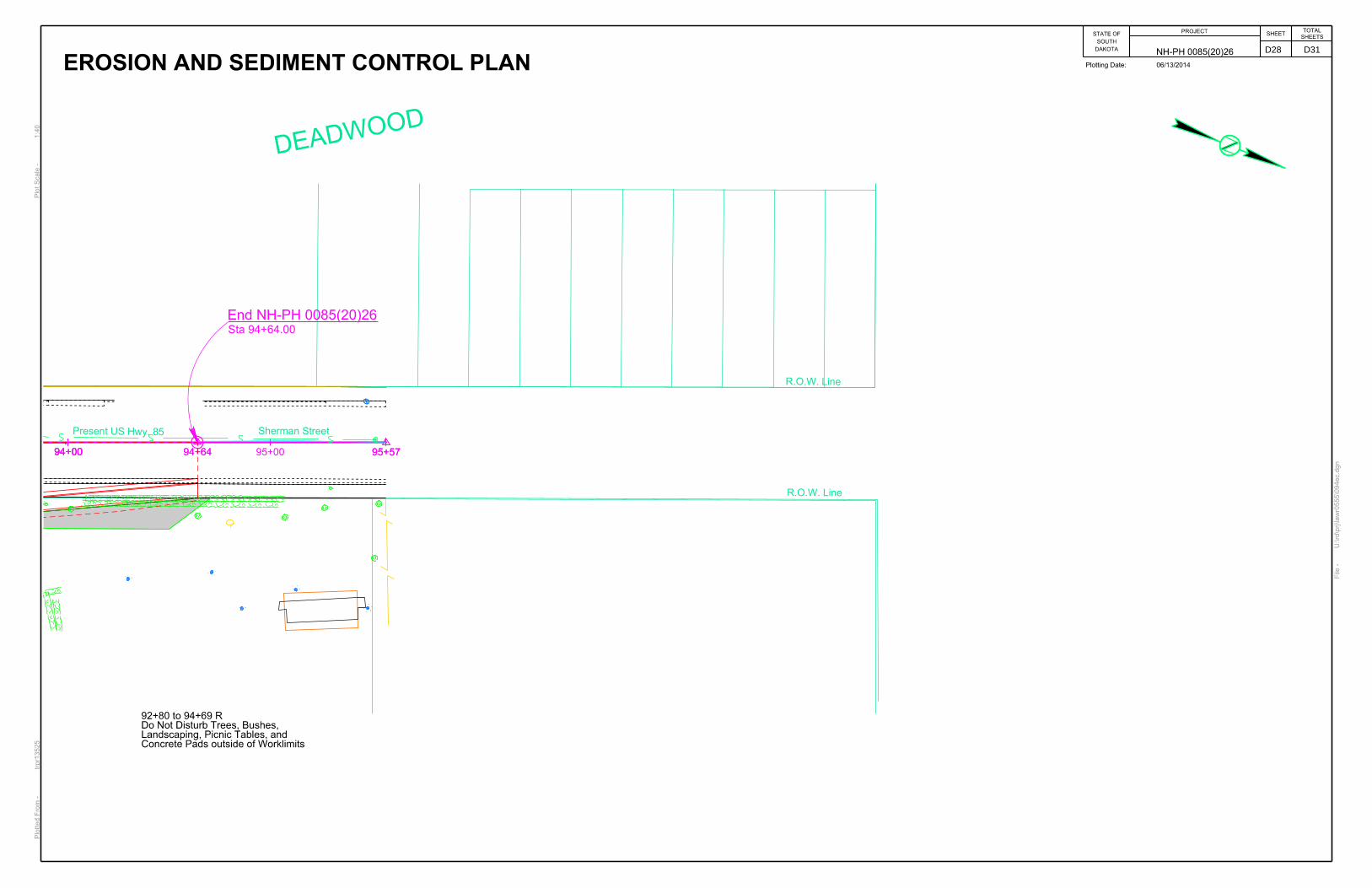
3525 Concrete Pads outside of WorklimitsLandscaping, Picnic Tables, andDo Not Disturb Trees, Bushes,92+80 to 94+69 R
End NH-PH 0085(20)26Sta 94+64.00
DEADWOOD
EROSION AND SEDIMENT CONTROL PLAN
R.O.W. Line
R.O.W. Line
D28 D31

DAKOTA
SOUTH
STATE OFPROJECT
SHEETSHEETS
TOTAL
NH-PH 0085(20)26
...\prj\la
wr0
555\s
73401s73405.d
gn
File -
Plotting Date: 06/13/2014
Plot Scale -
1:2
00
Plotted Fro
m -
trpr1
3525
D29 D31

DAKOTA
SOUTH
STATE OFPROJECT
SHEETSHEETS
TOTAL
NH-PH 0085(20)26
...\prj\la
wr0
555\s
73405s73410.d
gn
File -
Plotting Date: 06/13/2014
Plot Scale -
1:2
00
Plotted Fro
m -
trpr1
3525
D30 D31

DAKOTA
SOUTH
STATE OFPROJECT
SHEETSHEETS
TOTAL
NH-PH 0085(20)26
U:\rd\prj\la
wr0
555\s
73411.d
gn
File -
Plotting Date: 06/13/2014
Plot Scale -
1:2
00
Plotted Fro
m -
trpr1
3525
D31 D31