earthquake resistant masonry buildings
TRANSCRIPT
CONCEPTS FOR EARTHQUAKE RESISTANT MASONRY BUILDINGS…
Vertical cracking of brick masonry arches near the crown. Failure at corners of openings. Horizontal shear cracks due to poor strength of cement-sand ratio. Crack due to absence of horizontal band in brick and stone
masonry houses. Double brick masonry wall performed well. Most of government buildings constructed according to code have
performed well. Base of temple is not affected, due to sufficient length width ratio. Some well designed buildings were failed which are situated in
energy releasing line. Some houses were tilted and damaged due to liquefaction action. Old buildings were failed due to deterioration of strength and poor
workmanship.
Typical Types of damages due to Nepal earthquake 2072
Materials used for masonry building construction.1. Unit masonry: It may be brick, block made from
concrete or clay, stone etc.2. Mortar: It is plastic mixture of materials used to
bind unit masonry.3. Grout: It is mix of Portland cement, sand, gravel
and water. It is generally used for increasing the compressive strength of masonry.
4. Reinforcement: Reinforcement extends the characteristics of ductility, toughness and energy absorption that is very necessary in building subjected to earthquake forces.
Factors to be considered.. For seismic design of masonry buildings there
is need to consider strength and characteristics (compressive strength, shear strength, tensile strength) of masonry.
The modulus of elasticity, poisson’s ratio and damping properties are also required for seismic design of masonry buildings.
Followings are the major steps for determination of lateral loads:
1. Lateral load determination based on IS 1893 (part I):2002.
2. Distribution of lateral forces3. Determination of Rigidity of shear wall4. Direct Shear Forces and Torsional Shear forces5. Increase in axial load due to overturning
Lateral load analysis of masonry buildings.

1. Lateral load determination based on IS 1893 (part I):2002.Design seismic base SF( VB)= αhWValue of time period (Ta)= 0.09h/√d vertical distribution of Base shear to different floor levels,
Where, αh = hz. Seismic coeffh=height of building in md=base dimension of building along the lateral load dirn
W=seismic wt. of building.
Lateral load analysis of masonry buildings.
Lateral load analysis of masonry buildings.
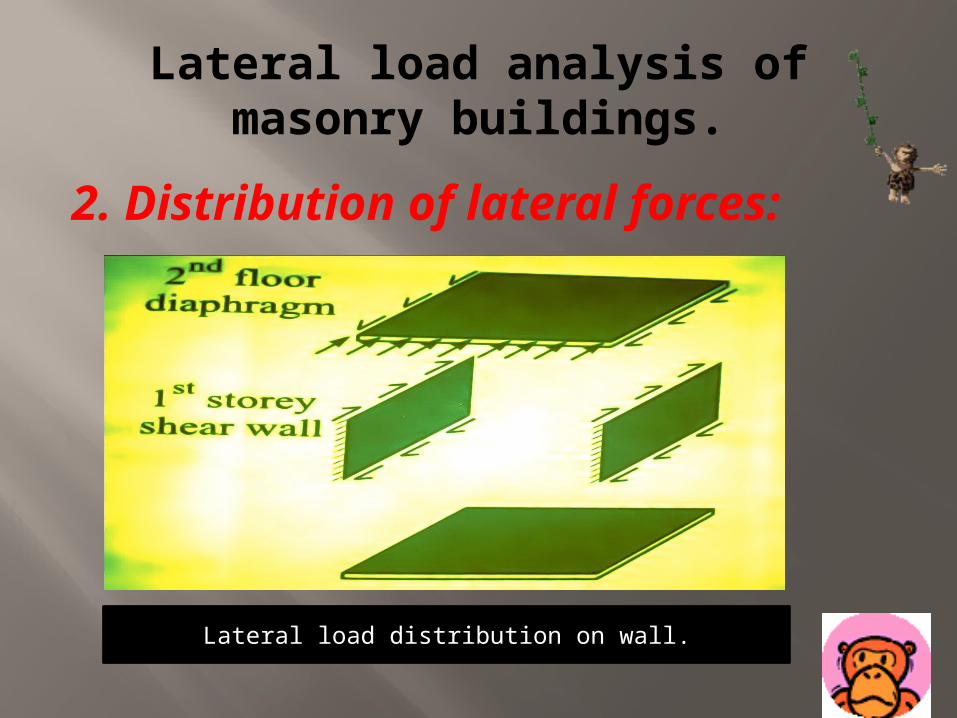
2. Distribution of lateral forces:
Lateral load distribution on wall.
Lateral load analysis of masonry buildings.3.Determination of Rigidity of shear wall:
In masonry structure, it is generally assumed that in one- and two- storey buildings the walls may be considered cantilevered and the walls between openings are called piers and might be considered fixed at top and bottom.
Lateral load analysis of masonry buildings.
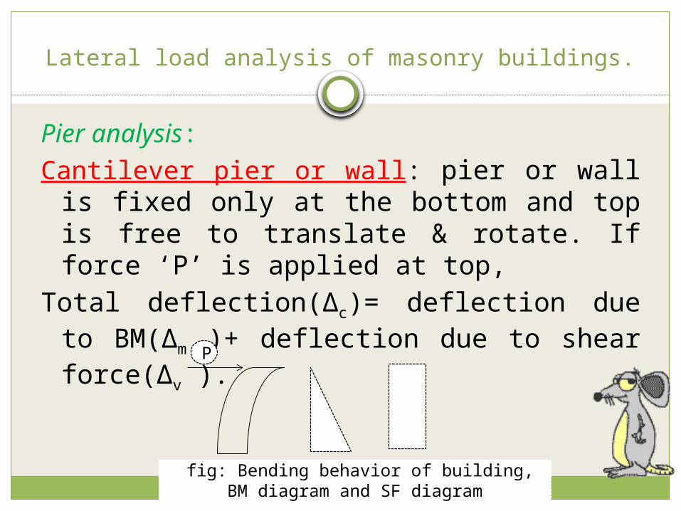
Pier analysis:Cantilever pier or wall: pier or wall is fixed
only at the bottom and top is free to translate & rotate. If force ‘P’ is applied at top,
Total deflection(∆c)= deflection due to BM(∆m )+ deflection due to shear force(∆v ).
P
Ffig: Bending behavior of building, BM diagram and SF diagram
Lateral load analysis of masonry buildings.
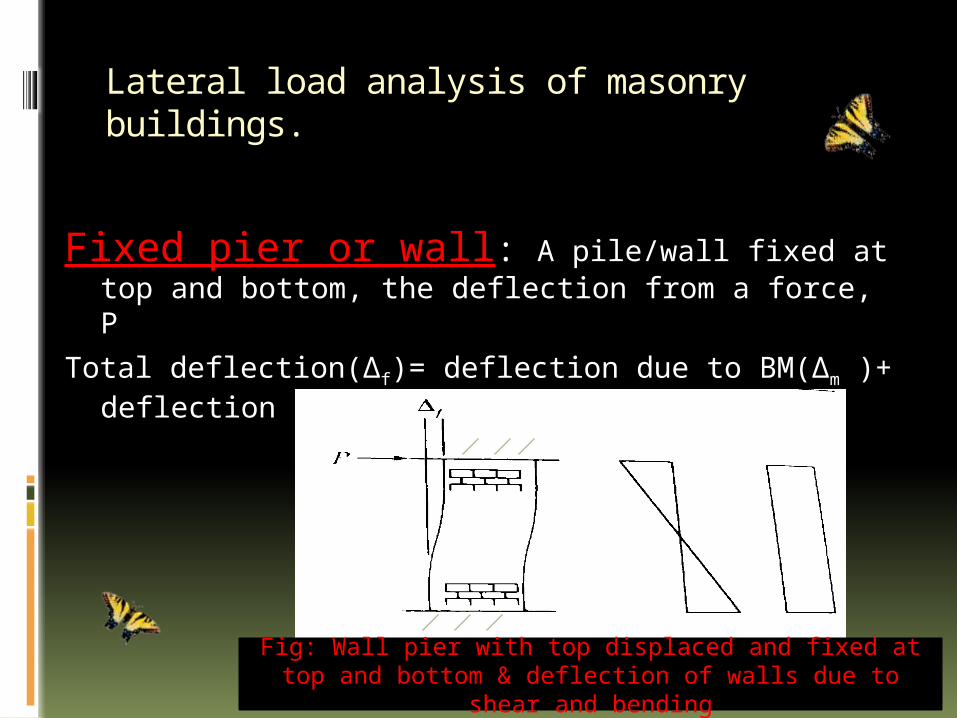
Fixed pier or wall: A pile/wall fixed at top and bottom, the deflection from a force, P
Total deflection(∆f)= deflection due to BM(∆m )+ deflection due to shear force(∆v ).
Fig: Wall pier with top displaced and fixed at top and bottom & deflection of walls due to shear and bending
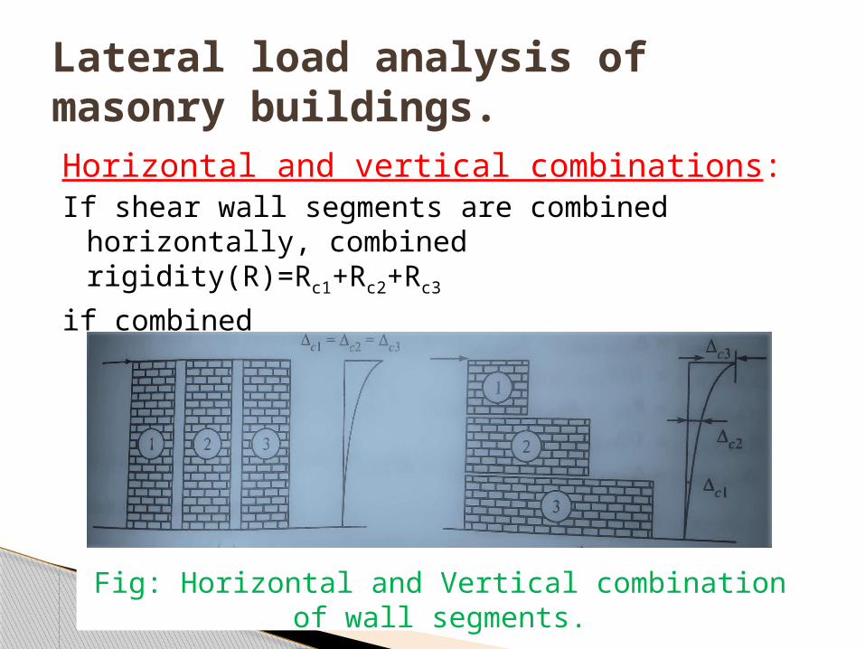
Horizontal and vertical combinations:If shear wall segments are combined horizontally, combined
rigidity(R)=Rc1+Rc2+Rc3
if combined vertically,(1/R)=1/Rc1+1/Rc2+1/Rc3
Lateral load analysis of masonry buildings.
Fig: Horizontal and Vertical combination of wall segments.
Lateral load analysis of masonry buildings.
4.Direct Shear Forces and Torsional Shear forces:
Direct Shear Forces: In the rigid diaphragm, walls are tied together with the diaphragm, The lateral force ‘P’ will be distributed to the walls to their relative stiffness. For any wall i, Direct shear force (VD)=RiP
Torsional Shear Force: When centre of mass and centre of gravity do not coincide, torsional shear force will induced on the wall.
Lateral load analysis of masonry buildings.
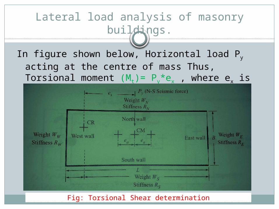
In figure shown below, Horizontal load Py acting at the centre of mass Thus, Torsional moment (Mt)= Py*ex , where ex is the distance between centre of rigidity and the line of force.
Fig: Torsional Shear determination
Lateral load analysis of masonry buildings.5.Increase in axial load due to overturning:In shear wall system, principle forces are1. In-plane shear = Direct SF + Torsional SF2. In-plane moment = In-plane shear * half of pier height.3. Dead loads & live loads.In addition to these forces sometimes, the lateral forces due to
earthquake or wind creates greater overturning on buildings. If overturning moment is very greater, it may cause tension at ends of pier of shear walls. It may also induce high compression forces on the pier of wall that may increase the axial load.
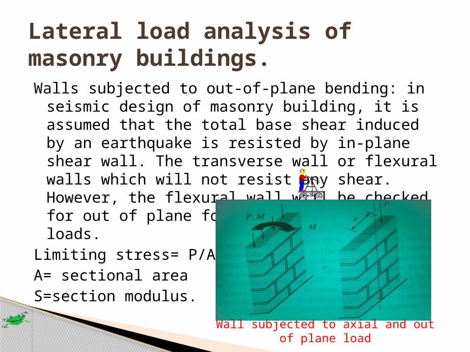
Walls subjected to out-of-plane bending: in seismic design of masonry building, it is assumed that the total base shear induced by an earthquake is resisted by in-plane shear wall. The transverse wall or flexural walls which will not resist any shear. However, the flexural wall will be checked for out of plane forces with the vertical loads.
Limiting stress= P/A+M/SA= sectional areaS=section modulus.
Lateral load analysis of masonry buildings.
Wall subjected to axial and out of plane load

….Thank you….