energy solutions - · pdf fileenergy solutions th e circumstances ... meanwhile, there is a...
TRANSCRIPT

592014 63-03Hitachi Review
Pow
er Systems
Energy Solutions
Th e circumstances under which energy infrastructure operates
are becoming more diverse at the national, regional, and environ-
mental level.
Th e major centers of demand for energy infrastructure are
shift ing from developed to emerging economies. Although
growth in demand is anticipated, few emerging economies have
established a grand design for their energy policies, and fi nancial
frameworks in many cases are weak. Th is means that proposals
need to include fi nancing. Furthermore, energy policies need to
be formulated on a comprehensive basis, encompassing not only
economics but also safety assurance and the environment. It is
also essential to consider consistency with these energy policies
when off ering to supply infrastructure in the form of a solution.
Th ere is oft en more than one way of implementing energy policy,
with a number of diff erent solutions possible depending on which
factors are prioritized. As it is anticipated that emerging
economies will experience ongoing urbanization and the concen-
tration of population, there is a need for effi cient (smarter)
operation of the energy infrastructure. In developed economies,
meanwhile, there is a shift away from coal and toward gas turbine
combined cycle (GTCC) and renewable energy in response to the
shale gas revolution and growing interest in environmental
protection. Also ongoing is a reorganization of power systems
to achieve separation between generators and transmission
businesses.
What is needed, then, is to look at power systems in terms of
the “3Es + S,” meaning not only economics but also energy
Hitachi’s Energy Solutions1 security and environmental conservation (3Es), and also safety
(S), the prerequisite for achieving these. In particular, an
important aspect of achieving energy security is the establishment
of an appropriate energy mix that does not rely on a single source
of energy. Key aspects of improving environmental conservation,
meanwhile, include compliance with restrictions on the emission
of the carbon dioxide (CO2) implicated in global warming, and
the installation of renewable energy sources such as photovoltaic
or wind power generation.
To resolve these complex issues that are closely tied up with
increasingly diverse social needs, it is necessary to collaborate on
identifying the issues faced by customers and other parts of
society and to off er order-made solutions.
It is these needs that the energy solutions supplied by the Power
Systems Company of Hitachi, Ltd. are intended to satisfy. In
addition to enhancing components, systems, and services sourced
from both inside and outside Hitachi, fusing these with informa-
tion technology (IT), and off ering leasing or other fi nancing
arrangements, Hitachi intends to propose comprehensive
solutions that include the thermal power systems supplied by the
new company formed through a business integration with
Mitsubishi Heavy Industries, Ltd. that commenced operation in
2014.
Hitachi intends to accelerate its activities as a solution provider
based around its comprehensive capabilities (which include IT,
logistics, and fi nance) working fl exibly in tandem with interested
parties from outside the company, and by establishing dedicated
teams to survey the problems faced by society and the wants and
needs of customers, to plan and devise solutions, and to coordi-
nate the providers of the diff erent components.
Energy Solutions
Economy
Energy securityEnvironmentalconservation
Safety Environmental problems
Increasingly diverse problemsand requirements
for nations, regions,and power customers
Provision of optimal solutions with a combinationof elements that suits customer needs
• Components• System proposals• Service enhancements
• IT fusion• Finance and leasing• Thermal power generation solutions• Comprehensive capabilities of Hitachi
Lack of capital
Energy security
Formulation of grand design for energyInstallation of renewable energy
Optimum distributed powersupply and demand
Grid stabilization
Power shortages
Human resource development
Overview of “3E +S” (left) and energy solutions (right)1

60 Power Systems
Power G
eneration Equip
ment and
Systems
Pow
er Systems
Hitachi supplied the turbines (used to drive generators supplied
from the UK) at the Bhakra Power Station in India that
commenced operation in 1959. In January 2008, a new order was
received for the large-scale refurbishment of the fi ve Francis
turbines, which by then were nearly 50 years old.
Th e overhaul of the fi rst turbine (Unit 2) commenced in April
2010. Due to cumulative delays at the site, the turbine did not
resume operation until July 2013, followed by a second turbine
(Unit 5) in October 2013. Th e refurbished turbines are currently
in full commercial operation. Refurbishment is also planned for
the remaining turbines, with work on a third (Unit 4) already
underway on site.
By updating the runners, which were produced for the refur-
bishment using optimal design and have a forward-swept blade
confi guration (in which the shroud end of the inlet side of the
blade is forward of the crown end relative to the direction of
rotation), and the guide vanes, Hitachi succeeded in signifi cantly
increasing turbine effi ciency. Similarly, increasing the output of
individual turbines by 16.6 MW, and total output by 83 MW, is
expected to make a major contribution to the tight electric power
supply situation in India. Also, whereas the old runners had been
periodically repaired to fi x cavitation damage, the signifi cant
improvement in cavitation bubble formation characteristics in
the relevant locations means that the upgraded runners will have
New Technology for Taking Maximum Advantage of Hydro Energy1 a longer operating life with less frequent repairs.
Th e specifi cations of the refurbished turbines are as follows.
Eff ective head: 134 m (normal)
Turbine output: 128 MW (max.)
Speed: 166.7 min-1 (rated)
(Hitachi Mitsubishi Hydro Corporation)
Hitachi has developed the G-HIACS* and deployed it in plant
upgrades such as the unit 1 automatic control system of the
Numappara Power Plant of Electric Power Development Co., Ltd.
and the supervisory control system of the Shin-Nariwagawa
Power Station of Th e Chugoku Electric Power Co., Inc. Aft er
commencing on-site installation in October 2013, these projects
have now completed commissioning and are in operation.
Compared to the previous HIACS* series, G-HIACS features
enhancements to maintenance tools in particular. Its main
features are as follows.
(1) Enhanced ability to analyze what is happening when faults
occur in sequence operation due to an upgrade to the trend
monitor to support recording of approximately 100 data points at
the computational cycle time (100 ms), compared to 48 points at
1-s intervals previously.
(2) Enhanced quality through logic debugging and easier simula-
tion of key equipment and control devices thanks to the addition
Latest Switchboard Upgrade Technology for Hydro Power Plants2
Power Generation Equipment and Systems
Unit 1 automatic control system of the Numappara Power Plant of Electric Power Development Co., Ltd.
2
128-MW Francis turbine for Bhakra Power Station in India1

612014 63-03Hitachi Review
Pow
er Systems
Power G
eneration Equip
ment and
Systems
to logic simulator mode of a function for specifying the changes
in analog signals and a one-shot function for digital signals.
Th e ND series of unit-type protection relays were used to
upgrade the protection systems for the Unit 4 motor-generator at
the Shin-Nariwagawa Power Station of Th e Chugoku Electric
Power Co., Inc. Th ese comply with the B-402 electric power
standard and IEC 60255 international standard, with features that
include the ability to enable or disable the relay elements, select
wide-band frequency characteristics, and customize the protec-
tion interlock circuit.
(Hitachi Mitsubishi Hydro Corporation)
* HIACS and G-HIACS are trademarks of Hitachi, Ltd.
Hitachi Mitsubishi Hydro Corporation used computational fl uid
dynamics (CFD) analysis to develop a turbine runner that features
improved effi ciency and reduced wear due to sediment abrasion
for the 23,300-kW Francis turbine at Unit 1 of the Himekawa No.
7 Power Station of Th e Tokyo Electric Generation Co., Inc. Th e
plant commenced operation with the upgraded runner in March
2012. Th e upgrade used a runner that was developed using a
shape design technique involving the use of a solid-liquid
two-phase fl ow analysis that modeled the fl ow of sediment to
assess those intricate parts of a runner that are diffi cult to protect
from sediment abrasion using surface treatments such as thermal
spraying. An inspection conducted aft er nine months of use in
December 2012 found no sediment abrasion. Th e upgraded
runner is scheduled to be installed on Unit 2 in February 2014.
Th e 35,000-kW Francis turbine at the Shin-Inotani Power
Station of the Hokuriku Electric Power Company commenced in
May 2013 aft er a runner upgrade to improve cavitation character-
istics was undertaken using CFD analysis. Th e turbine uses a
Characteristics Improvement through Use of CFD in Runner Upgrade3
runner with forward-swept blades in which the blade shape twists
three-dimensionally and has a shape that prevents the formation
of the localized pressure drops associated with cavitation. Use of
this runner shape has resulted in stable operation.
(Hitachi Mitsubishi Hydro Corporation)
Although the Jebba Hydro Power Plant in the Federal Republic of
Nigeria plays an important role, accounting for approximately
15% of the nation’s generation capacity, it is currently operating
at about half-capacity due to damage to the No. 4 generator
incurred aft er an accident on the power grid in 2009. In December
2012, Hitachi Mitsubishi Hydro Corporation tendered for the
emergency repair of the plant and was awarded a contract for the
project based on its proposal to refurbish the plant’s existing
Hitachi, Ltd. equipment. Th e on-site refurbishment work is
planned to take a minimum of eight months, from March to
October 2014.
Th e Baluchaung No. 2 Hydro Power Plant in Republic of the
Union of Myanmar accounts for approximately 10% of the
nation’s generation capacity, and thanks to its abundant water
resources, operates as a reliable year-round, base-load generator.
However, progressive aging and deterioration of the plant’s
equipment due to continuous operation since it entered service in
1960 means there is a need to repair and replace the equipment in
the near future. Tendering for the rehabilitation project took
place in June 2013, with Hitachi Mitsubishi Hydro Corporation
being awarded the contract based on its proposal to refurbish the
plant’s existing Hitachi equipment. Th e plan is to perform on-site
repairs and replaces to a total of six units from July 2014 to March
2016.
(Hitachi Mitsubishi Hydro Corporation)
Orders for Emergency Repair of Jebba Hydro Power Plant in Nigeria and Rehabilitation of Baluchaung No. 2 Hydro Power Plant in Myanmar
4
The region (shown in red) of high sediment abrasion on the band side of the outlet edge of the existing runner is clearly smaller on the upgraded runner.
The localized region (shown in blue) of low pressure near the inlet on the band side of the existing runner does not occur on the upgraded runner.
Existing runner
Band surface Band surfaceBand
surfaceBand surface
Outlet edgeOutlet edge
Inlet edge Inlet edge
Turbine runner for Himekawa No. 7 Power Station Turbine runner for Shin-Inotani Power Station
Existing runner
Suction surfaceinlet region
Pressure surfaceoutlet region
Pressure surfaceoutlet region
Suction surfaceinlet region
Upgraded runner Upgraded runner
Upgraded runner shape and improvements made through use of CFD3

62 Power Systems
Power G
eneration Equip
ment and
Systems
Pow
er Systems
Th ere are three levels of contaminated water at the Fukushima
Daiichi Nuclear Power Station; highly contaminated water in
reactor buildings and turbine buildings, concentrated brine
discharged from reverse osmosis (RO) desalination systems, and
relatively low contaminated water that has been collected from
sub-drains located around buildings. Th is water has various levels
of contamination, and contains a variety of radioactive nuclides
that include cesium (Cs-134 and Cs-137), strontium (Sr-89 and
Sr-90), and antimony (Sb-125). To respond to this diffi cult
situation, Hitachi-GE Nuclear Energy has developed a contami-
nated water treatment system specifi cally for treating sub-drain
water.
Th e main features of the system are as follows.
(1) Pre-treatment fi lters including not only conventional fi lters
but also fi lters that can remove colloids
(2) Hitachi-GE Nuclear Energy’s newly developed superior
adsorbent to simultaneously remove Cs and Sr
(3) A fl exible system with a sophisticated modular design to allow
a combination of optimum adsorbents from all over the world
when multi-nuclide removal is required
Th e new system will reduce the concentration of radioactive
nuclides in sub-drain water to below discharge limits. By installing
the system at the Fukushima Daiichi Nuclear Power Station,
Hitachi is making a continuing contribution to the treatment of
Sub-drain Water Purifi cation System5
contaminated water.
(Hitachi-GE Nuclear Energy, Ltd.)
Even aft er the accident at Fukushima Daiichi Nuclear Power
Station, the UK government has stuck to its policy of encouraging
nuclear power and is proceeding with the introduction of a
feed-in tariff scheme to guarantee the purchase price of nuclear
power because of its status as low-carbon energy source. Th e laws
relating to this electricity market reform were introduced into
parliament in November 2012 and are scheduled to become law
during 2014.
In November 2012, Hitachi purchased all issued stock in the
UK nuclear power development company, Horizon Nuclear
Power Limited.
Horizon Nuclear Power plans to construct two or three 1,300-
MW-class advanced boiling water reactors (ABWRs) at each of its
two sites (at Wylfa and Oldbury), with the fi rst reactor scheduled
to commence generation in the fi rst half of the 2020s. To this end,
the UK’s Offi ce for Nuclear Regulation and the Environment
Agency embarked on a Generic Design Assessment process in
April 2013. Hitachi is also expediting its activities aimed at
advancing construction plans at the Wylfa site, including a plant
design prepared to UK specifi cations and the establishment of
supply chain management.
By adding a nuclear power business to its existing railway
business in the UK, Hitachi believes it can contribute to advances
in social infrastructure in the country, including employment.
Project for Construction of New Nuclear Power Plants in UK6
Sub-drain supply tank
23 m
25 m
• Daily treatment capacity of 1,200 m3 (100% × two systems for high reliability)• Compact system configuration covering area of 23 m × 25 m (planning stage)• Adsorption vessels can be replaced using forklifts (does not require installation of a crane).• Flexible configuration and quick site installation by modular design• System produces its own compressed air.
Features
6 m
Electricalroom
Cs/Sr adsorptionvessels
Multi-isotopeadsorption vessels
Bird’s eye view of system
Sub-drain supply pump
Pre-treatment filters
Csfilter
Srfilter Forklift m
arshaling
area
Compressedair supply
Sub-drain water purifi cation system5
Interiors of the Jebba Hydro Power Plant in Nigeria (top) and the Baluchaung No. 2 Hydro Power Plant in Myanmar (bottom)
4

632014 63-03Hitachi Review
Pow
er Systems
Power G
eneration Equip
ment and
Systems
With sunlight recognized as a form of renewable energy, the
number of large photovoltaic power generation systems with
capacities greater than 1 MW is growing rapidly. To improve the
effi ciency and reduce the installation costs for photovoltaic power
generation systems, an increasing number of these systems are
adopting a direct current (DC) voltage of 1,000 V, the standard
outside Japan, in place of the 600 V used in the past.
In response, Hitachi has added the 660-kW power conditioning
system (PCS), which can work with DC voltages in the 1,000-V
range, to its line-up of PCSs for megasolar power plants. Th e
inverter in the 660-kW PCS uses a three-level conversion circuit
with high reverse conversion effi ciency. It has a maximum effi -
ciency of 98.8% (at 520 V DC), and is able to maintain high effi -
ciency (98% or more) over alternating current (AC) outputs of
between 5% and 90% (at 620 V DC). It also incorporates grid
stabilization functions as standard features, including functions
for suppressing voltage fl uctuations and for adjusting reactive
power, including a function for maintaining constant power
factor. An outdoor package that includes three 660-kW PCSs has
also been added to the product range. Th e ability to confi gure a
2-MW-class power generation system using a single outdoor
package helps reduce the space requirements and cost of installa-
tion.
As it is forecast that photovoltaic power generation systems will
Power Conditioner for Megasolar Power Plants7
switch to 1,000-V DC operation in the future, growth in demand
is anticipated.
(Product release date: November 2013)
Hitachi has participated in the Chinese market for wind power
converters since 2008. Its products for this market have consisted
to date of 1.5-MW and 2.0-MW converters for doubly fed (DF)
generators and a 2.0-MW converter for permanent magnet
generators (PMGs). (Th e 1.5-MW DF converter commenced
operation in October 2010, the 2.0-MW DF converter in July
2013, and the 2.0-MW PMG converter in December 2012).
Th e newly developed 3.0-MW water-cooled DF converter
provides greater capacity than the 2.0-MW air-cooled model, and
is a response to demand from the Chinese market for higher
capacity wind power generators.
Its main features are as follows.
(1) Suitable for sites with sudden changes in wind and at which
turbines are frequently taken in and out of service
(2) Able to continue operating through short-duration spikes in
the grid voltage (130% of rated voltage for 0.1 s)
(3) Able to continue operating through short-duration fl uctua-
tions in the grid frequency [rated frequency (50 Hz)±10 Hz for
0.5 s (+10 Hz) or 0.2 s (–10 Hz)]
(4) An independently operating converter connected to the grid
can output reactive power.
(5) 2,415 mm (W) × 600 mm (D) × 2,190 mm (H) (excluding
protrusions), weight: 2,600 kg
(6) Capacity:volume ratio: 1.01 MW/m3
(7) Water cooled: fully enclosed recirculated cooling
In the future, Hitachi intends to build its experience in the
renewable energy sector by conducting verifi cation tests of low-
voltage ride through (LVRT), also available on the 1.5-MW and
2.0-MW DF models. Additional models are also planned along
with deployment in Japan.
3.0-MW DF Converter for Wind Power Generation8
99.0
98.8
98.6
98.4
98.2
98.0
97.8
97.60 20 40 60
DC 520 V
DC 620 V
DC 720 V
DC 800 V
Output (%) (100% = 660 kW)
Example efficiency characteristics (typ.)660-kW PCS
1,400 mm (W) × 1,000 mm (D) × 1,900 mm (H)
Effic
ienc
y (%
)
80 100
Power conditioner for megasolar7
Artist’s impression of completed Wylfa Newydd Power Station6

64 Power Systems
Power G
eneration Equip
ment and
Systems
Pow
er Systems
Demand for renewable energy has been on the rise in recent
years, with growing interest in wind power as a source of domestic
energy production in Japan. While most of the wind power
generation systems currently operating in Japan are land-based,
off shore sites typically have higher wind speeds and it is antici-
pated that they will become more common due to this and other
advantages, including being less likely to cause diffi culties due to
noise or impact on scenery.
Compared to onshore sites, construction of off shore wind
farms requires greater investment due to higher costs that include
building foundations, installation, and laying undersea cables.
Accordingly, using a smaller number of turbines with higher
output is seen as a way of improving the profi tability of wind
farms, and this has led to demand for even larger wind power
generation systems than systems in the 2-MW to 3-MW class that
are large by the standards of onshore sites.
Th e 5-MW downwind turbine currently being developed for
off shore use not only has a higher output than the previous 2-MW
model, it also incorporates a medium-speed gear drive mechanism
that combines permanent magnet synchronous generator with a
speed-increasing gear with a ratio of approximately 1:40. Th e
system will also help reduce wind farm construction costs thanks
to a lighter and more compact nacelle that reduces the over-
Large 5-MW Off shore Wind Power Generation System9
turning moment of the downwind turbine and allows a more
practical foundation design.
Progress has been made in recent years on utilizing renewable
forms of energy such as sunlight and wind. In Japan, a feed-in
tariff scheme was introduced in 2012 following the passing of the
“Act on Special Measures Concerning Procurement of Renewable
Energy Sourced Electricity by Electric Utilities” in August 2011.
Th is has led to a rapid expansion in plans for the installation of
photovoltaic power generation systems and work is underway
throughout Japan on the construction of large systems.
Hitachi has been involved in the development of high-capacity
PCSs for large photovoltaic power plants and is anticipating the
installation of several hundred megawatts of generation capacity,
including a megasolar power plant at Ashikita that commenced
operation at the end of 2013 and the 82-MW Oita Mega-solar
Power Plant, Japan’s largest class, which is scheduled to start
generating power in the spring of 2014.
Th e Oita Mega-solar Power Plant being built in Oita City, Oita
Prefecture to be operated by Oita Mega-solar Power Co., Ltd. will
be the largest class such plant in Japan, with a 105-hectare site
(1,050,000 m2) and generation capacity of 82 MW. It is forecast to
generate 87,000 MWh of electric power annually, enough for
about 30,000 typical homes. If all of the solar panels in this very
large system were laid in a line, they would stretch for approxi-
mately 500 km, roughly the distance from Tokyo to Osaka.
Meanwhile, vigorous eff orts are being made to achieve further
improvements in the effi ciency of the PCS, a core component of
photovoltaic power generation. In addition to the existing
500-kW model with a DC voltage of 600 V, Hitachi has also
commenced sale of a 660-kW model that can operate at 1,000 V
DC. Th is PCS uses a three-level inverter for a chopper-less design
that delivers a world-leading level of conversion effi ciency, with a
maximum effi ciency of 98.8%. Drawing on its past experience in
engineering, procurement and construction (EPC), Hitachi is
also enjoying strong sales for its package that bundles the main
equipment needed for a medium-sized photovoltaic power
generation system.
In the future, Hitachi intends to continue operating a broad-
based photovoltaic power generation business that extends from
medium to large systems, primarily in Japan, while also working
aggressively to expand its business in overseas markets.
Megasolar System10
Power plant of SGET Ashikita Mega Solar LLC10 Large 5-MW off shore wind turbine9
3.0-MW DF converter for wind power generation8

652014 63-03Hitachi Review
Pow
er Systems
Electric Power Transm
ission Equip
ment and
Systems
Kyushu Electric Power Co., Inc. is undertaking a full upgrade of
its integrated control center systems, and is building the
Kumamoto Integrated Control Center System under the supervi-
sion of Seiko Electric Co., Ltd. Th e upgrade will merge two
existing integrated control centers, resulting in the new system
being responsible for the monitoring and control of generation
and substation facilities at approximately 200 sites. Th e system is
currently undergoing fi nal commissioning in preparation for
commencing operation in April 2014.
Th e main features are as follows.
(1) Very high system reliability. Th e computer that underpins the
online monitoring and control functions has a triply redundant
confi guration to allow for maintenance or faults, and the
computer that handles operational support functions, such as
issuing operating command sheets, has a doubly redundant
confi guration.
(2) A grid status panel that uses a projector-based display system
and is designed to facilitate the eff ective sharing of information
between the staff on duty. Th is includes grid information such as
the constantly changing fl ow of electric power, and weather infor-
mation such as thunderstorm warnings.
(3) Reduced workload for staff on duty. Functions include partial
automation of grid reliability monitoring and the preparation of
fault recovery procedures and operating orders.
Kumamoto Integrated Control CenterKyushu Electric Power Co., Inc.1
In order to protect equipment by, for example, quickly discon-
necting a generator from the grid and performing an emergency
stop in the event of an internal electrical fault, the generator
protection relays used in thermal, hydro, and other forms of
power generation require high reliability and the selectivity to
accurately detect the faults they are intended to catch. A new
multi-function unit-type protection relay developed by Hitachi
provides this selectivity and reliability as well as complying with
the IEC 60255 international standard. It includes an English-
language human interface and has the fl exibility for use in a
variety of diff erent protection system applications.
Th e main features are as follows.
Enhancements to Generator Protection Relay2
Electric Power Transmission Equipment and Systems
Unit-type protection relay2
Kumamoto Integrated Control Center of Kyushu Electric Power Co., Inc. (control room)1

66 Power Systems
Electric Power Transm
ission Equip
ment and
Systems
Pow
er Systems
(1) Can be customized using engineering tools to perform protec-
tion, measurement, and control in ways that are specifi c to the
application. Th is includes the ability to select the protection relay
element and wide-band frequency characteristics, and to build
protection sequence circuits.
(2) Designed for use with analysis tools that can perform measure-
ment, oscillography, and event logging for the collection and
analysis of grid data.
(3) Compact, swappable design in which the modules required
for the protection relay are housed in a single unit case. It also
features improved toughness, with temperature characteristics,
electromagnetic compatibility (EMC), and seismic ratings that
comply with the IEC 60255 international standard.
In the future, Hitachi intends to make the tools more effi cient to
use and extend the product range to expand the scope of applications.
Hitachi is conducting joint demonstrations with Kyushu Electric
Power Co., Inc. on a demonstration smart grid built by the power
company in Satsumasendai City, Kagoshima Prefecture, Japan
that was completed in October 2013.
Th e demonstration smart grid includes photovoltaic power
generation, lithium-ion batteries, a simulated power distribution
system (simulated power lines, simulated loads, and voltage regu-
lation equipment), and an energy management system that
measures, monitors, and controls the output, voltages, currents,
and other parameters of these systems. Th e total outputs of the
photovoltaic power generation system and lithium-ion batteries
are 278 kW and 118 kW respectively, and they provide both high-
voltage and low-voltage grid connections.
Th e demonstration project involves using these systems to trial
various ways of overcoming the supply and demand and voltage
problems that are associated with the connection of large amounts
of photovoltaic generation capacity. In the case of supply and
demand, this consists of collecting data on parameters such as
sunlight intensity and photovoltaic power generation, and battery
charging, discharging, and state of charge, and using it to test
methods for predicting the output of photovoltaic power genera-
Demonstration Smart Grid (Satsumasendai Area)Kyushu Electric Power Co., Inc.
3
tion and for optimizing control of the batteries. In the case of
voltage, the project will test optimized voltage control methods by
conducting experiments on the sort of voltage management
problems that are likely to occur on future distribution systems,
using the simulated load to generate fl uctuations in the grid load,
and then collecting and analyzing data on resulting power line
voltages, currents, and other parameters.
Th e demonstrations are scheduled to continue until March
2015.
Since FY2011 Hitachi has been participating in the “Demonstra-
tion Projects for Next Generation Power Control Systems by
Two-way Communications” funded by the Agency for Natural
Resources and Energy of the Ministry of Economy, Trade and
Industry, Japan. Th e objective of these demonstration projects is
to investigate the stabilization of power grids that include
extensive photovoltaic power generation. As part of this work,
Hitachi is demonstrating the monitoring and control of a power
conditioning system (PCS) at Rokkasho-mura in Aomori Prefec-
ture and two other sites, which use a communications system to
regulate power output.
Hitachi is trialing a two-way communication system that
controls PCS output via specifi ed low-power radio or Japan’s
various cellular phone networks. Th e tests conducted over four
periods, starting in December 2012 and covering each of the four
seasons, have achieved favorable communications in a variety of
weather conditions. By measuring the radio transmission charac-
teristics of the diff erent communication methods, the tests
succeeded in combining diff erent forms of radio communication
Demonstration Project for Next-generation Output Control Using Two-way Communication4
Demonstration smart grid (Satsumasendai area) of Kyushu Electric Power Co., Inc.
3
RSSI(dBm)
429 MHz/10 mW
Repeater Repeater
920 MHz/10 mW
−70
−65
−60
−55
−50
−45
−40
−75
−80
−85
−90
Communitycenter
Communitycenter
Repeater (top) and radio transmission characteristics (bottom) for specifi ed low power radio
4
RSSI: received signal strength indication

672014 63-03Hitachi Review
Pow
er Systems
Electric Power Transm
ission Equip
ment and
Systems
to suit the local conditions.
Th rough these year-round, long-run trials, the demonstration
project indicated that it is possible to implement a communica-
tion system that can perform detailed control of PCS output.
Th e island of Maui in Hawaii is by far the most oil-dependent part
of the USA, with electricity tariff s three times higher than those
on the mainland due to the rising price of oil. It is also a site of
rapid progress on the introduction of renewable energy, with
plans to replace 40% of total power generation on the island with
renewable energy by 2030.
It is against this background that a project has been launched
on Maui aimed at supporting the large-scale use of electric
vehicles (EVs), maximizing use of renewable energy, and ensuring
the security of electric power supply.
Together with the State of Hawaii, County of Maui, Hawaiian
Electric Company, Inc., Maui Electric Company, Ltd., Th e
University of Hawaii, and US national research laboratories,
Hitachi has been contracted by the New Energy and Industrial
Technology Development Organization (NEDO) to participate
in its Japan-U.S. Island Grid Project in Maui (project name:
JUMPSmartMaui).
Quick charging stations have been installed at fi ve sites around
the island, chosen based on an analysis that considered traffi c
fl ow and the distances to homes, offi ce districts, and tourist sites.
A further 15 stations are planned. In addition to encouraging the
wider adoption of EVs by making them easier to use, the project
will also establish an energy infrastructure for the island that is
not dependent solely on fossil fuels by using the energy storage
capacity of EVs for surplus power absorption and to stabilize
renewable energy. Th ere are also plans to expand it to include a
virtual power plant (VPP) function that contributes to the energy
supply and demand balance for the entire island through the inte-
Japan-U.S. Island Grid Project5
grated management of the decentralized energy resources.
(Commencement of operation: December 2013)
Th e Kashiwa-no-ha Smart City Project aims to achieve safe,
secure, and sustainable urban development in the form of a city
that provides a model for the future through a collaboration
between the public, private, and academic sectors. Based around
the central Gate Square district, it provides support for making
signifi cant reductions in carbon dioxide (CO2) emissions and for
the local community’s business continuity plan (BCP), including
the provision of backup lines of energy supply for the entire
region and the eff ective use of renewable and unused sources of
energy.
Th e project involves installing independent power lines within
the district so that locally produced electric power from storage
batteries installed at major facilities can be distributed to buildings
that normally have secure and reliable supplies of grid power but
experience peak demand at diff erent times. Th is also provides a
bare-minimum supply of domestic electric power to the
surrounding neighborhood in the event of a grid power outage.
Th e equipment supplied to the project by Hitachi included one
of Japan’s largest stationery lithium-ion batteries (3,800 kWh), a
system for the electric power interchange device between diff erent
parts of the city, distribution equipment, and also an area energy
management system that not only monitors, controls, and
operates these other systems, but also provides residents with
information such as the mechanisms of energy use and guidance
on their behavior.
In the future, Kashiwa-no-ha plans to construct a network that
covers the entire city while also expanding the coverage area of its
“Smart Grid Model Based on Grid Power Coordination” and
adding additional functions.
(Scheduled commencement date: April 2014)
Kashiwa-no-ha Smart CitySmart Grid Model Based on Grid Power Coordination
6
M2M network
μDMS
μDMS
Efficiency
Efficient use of large amounts of renewable energy
Advanced load shifting technology
Use of direct controlto respond to sudden changes
in supply and demandDirect load control technology
Detailed control of energyusing distributed controlμDMS RF mesh network
Security measuresto ensure system safety
M2M network security technology
Combines system-wideoptimization with QOL.
Integration of informationand control
Establishment of equipmentand systems
for widespread use of EVsM-to-N charging management
system for EVs
Stabilization and balancing
EV station
Security
Vertical integration
Smart city center
Solutions supplied to demonstration project by Hitachi5
M2M: machine to machine, DMS: distribution management system, RF: radio-frequency, QOL: quality of life

68 Power Systems
Electric Power Transm
ission Equip
ment and
Systems
Pow
er Systems
Since the 1970s, Hitachi has supplied a total of more than 40 large
transformers to the Kingdom of Saudi Arabia. Th is has included a
series of major orders since 2005 for large transformers of 500
MVA or more for use in power plants, with on-site installation
currently in progress at the same time as work proceeds on design
and fabrication for new orders.
Products for the Kingdom of Saudi Arabia require special spec-
ifi cations to deal with the harsh environmental conditions,
including limits on temperature rise. In addition to giving full
Ongoing Supply of 380-kV Transformers to Saudi Arabia7 consideration to these requirements prior to design and fabrica-
tion, Hitachi also takes advantage of the ongoing orders to hold
periodic technical consultations with customers to deepen the
relationship of trust through the exchange of information about
the reasons behind the specifi cations and other technical issues.
In recent times, Hitachi has utilized these relationships to enter
into discussions about future projects.
With numerous plans for power plant construction in Saudi
Arabia in response to rising demand, Hitachi intends to draw on
its past experience to meet the demand for large power plant
transformers while also strengthening cooperation with the
customers.
Th e newly developed 154-kV-class earthquake-proof transformer
uses 154-kV-class direct-molded bushings made by SWCC Showa
Cable Systems Co., Ltd., which use new materials and feature
light weight and small size, and also provides improved earth-
quake resistance due to a lower center of gravity for the completed
transformer and greater rigidity in the bushing attachments.
Th e transformer also has a function for instantaneous and
automatic recovery if the pressure of sloshing transformer oil
during an earthquake causes a relief valve to open.
Instead of using oil for insulation, the direct-molded bushings
have an insulation design in which a coating of silicone rubber is
laid directly over epoxy resin. In addition to eliminating the risk
of oil leaks, this is also approximately 80% lighter and 40% smaller
than the porcelain-insulated bushings used previously. Th is
lighter weight and smaller size increases the natural frequency,
thereby reducing the risk that resonance with the seismic
154-kV-class Earthquake-proof Transformer8
Area energy managementProvision of information to users
Kashiwa-no-ha Smart City 2020
Electric power interchange
• Show regional energy situation, analysis, and management.• Monitoring of distribution and load networks• Monitoring of disaster information• Energy efficiency management using ranking indicators
• Provision of area energy information• Raise awareness of power saving among users. • Set targets for energy consumption. • Energy consumption warnings • Present advise on energy efficiency. • Monthly actual energy consumption
Background image courtesy of Mitsui Fudosan Co., Ltd.
• Establish plans for electric power interchange. • Cut peak demand during normal times. • Power saving during planned outages • Coordination of supply capabilities of different areas during planned outages or disasters• Operation of electric power supply and demand control
Kashiwa-no-ha Smart City6
Factory testing of fi rst 900-MVA-class power plant transformer (four transformers are to be supplied in total)
7

692014 63-03Hitachi Review
Pow
er Systems
Electric Power Transm
ission Equip
ment and
Systems
vibration will cause large stresses in the bushings. As restrictions
on the angle of attachment of the bushings have also been elimi-
nated, the new transformer provides more fl exibility in layout
design, making it suitable for a wider range of applications.
A gas circuit breaker (GCB) is a grid protection device that can
perform rapid switching of high voltages and heavy currents.
Although Hitachi has already supplied about 40 800-kV GCBs
(for the highest voltage level in North America) with double
mechanisms per phase, there is demand for single-mechanism
models for greater reliability and easier maintenance. Accord-
ingly, Hitachi has developed a single-mechanism GCB with the
high performance to comply with both the latest IEEE standards
and customer specifi cations.
800-kV GCB for North American Market9
Th e GCB is rated for 800 kV, 4,000 A, breaking current of 50
kA, and 60 Hz. Its main features are as follows.
(1) Easier maintenance and greater reliability from using a single
mechanism to drive two contacts, reducing the operational vari-
ability inherent in the design compared with the dual-mechanism
GCBs used in the past.
(2) Achieving duties complies with latest standards and customer
specifi cations, thanks to mechanical systems that have been made
lighter and faster through the fl uid and strength analyses.
(3) Easier operation and lower failure rate achieved through
lower component count and simplifi ed design.
Hitachi’s aim is to continue expanding its share of the North
American GCB market.
Gas-insulated switchgear (GIS) and GCBs have an important role
in the electrical conversion equipment used in the distribution of
electric power. In operating its business globally, Hitachi demands
high-quality products, not only from its Japanese facilities but
also from production at overseas affi liates.
Th e newly developed Global (GIS, GCB) Kokubu (Kumitate)
Instruction Training System (G-KITS) is a system for guiding
workers through assembly work to ensure consistent quality. It
incorporates operating procedures and automatic monitoring of
work quality.
Th e main features are as follows.
(1) Clear and easy-to-understand work instructions using three-
dimensional animations.
(2) Realtime data collection made possible by the use of digital
approvals implemented through the adoption of information
technology (IT) in the workplace to replace the paper- and
rubber-stamp-based practices used for work records in the past.
(3) Uses digital torque wrenches to prevent problems such as
bolts being missed or tightened with insuffi cient torque, and uses
the associated work records to perform automatic monitoring.
Assembly Guidance System for Switchgear10
800-kV GCB developed and supplied by Hitachi (single-mechanism model)9
Silicone rubber coating Epoxy resin
Flange
Unit: mm
ParameterPorcelain(154-H)
Direct-molded(154D-M)
120 kg (approx.)
310 mm
1,860 mm
590 kg (approx.)
515 mm
2,970 mm
Up to 0.12 mg/cm2
Mass
Maximumdiameter
Total lengthexposed to air
Contaminationrating
Internal conductor
3601,860
154-kV direct-molded bushing (154D-H)
Use: transformer with high-side nominal voltage of 154 kVCan be used with transformers up to approximately 500 MVA.
154-kV direct-molded bushing
Design of 154-kV direct-molded bushings made of new materials (top) and overview of earthquake-proof transformer (bottom)8
70 Power Systems
Electric Power Transm
ission Equip
ment and
Systems
Pow
er Systems
Kokubu Engineering & Product Division at Hitachi Works,
Hitachi, Ltd. is designated by Hitachi as a “mother factory.” Th e
division has set up a model production line using G-KITS to
conduct verifi cation testing, including actual assembly. Aft er its
initial use in the assembly of 145-kV GCBs, the system was subse-
quently adopted at Hitachi (Suzhou) EHV Switchgear Corpora-
tion, an overseas affi liate.
In the future, Hitachi intends to extend use of G-KITS to other
standardized models and will consider adopting it at other
overseas affi liates.
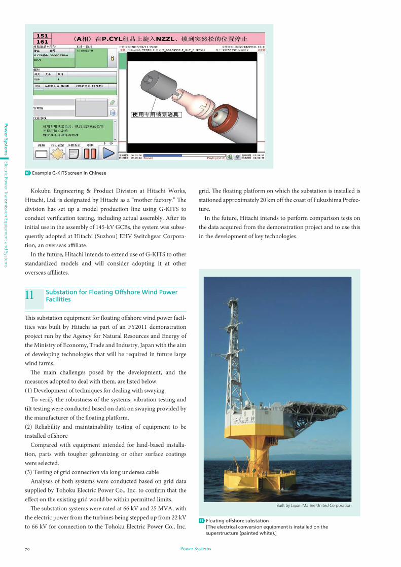
Th is substation equipment for fl oating off shore wind power facil-
ities was built by Hitachi as part of an FY2011 demonstration
project run by the Agency for Natural Resources and Energy of
the Ministry of Economy, Trade and Industry, Japan with the aim
of developing technologies that will be required in future large
wind farms.
Th e main challenges posed by the development, and the
measures adopted to deal with them, are listed below.
(1) Development of techniques for dealing with swaying
To verify the robustness of the systems, vibration testing and
tilt testing were conducted based on data on swaying provided by
the manufacturer of the fl oating platform.
(2) Reliability and maintainability testing of equipment to be
installed off shore
Compared with equipment intended for land-based installa-
tion, parts with tougher galvanizing or other surface coatings
were selected.
(3) Testing of grid connection via long undersea cable
Analyses of both systems were conducted based on grid data
supplied by Tohoku Electric Power Co., Inc. to confi rm that the
eff ect on the existing grid would be within permitted limits.
Th e substation systems were rated at 66 kV and 25 MVA, with
the electric power from the turbines being stepped up from 22 kV
to 66 kV for connection to the Tohoku Electric Power Co., Inc.
Substation for Floating Off shore Wind Power Facilities11
grid. Th e fl oating platform on which the substation is installed is
stationed approximately 20 km off the coast of Fukushima Prefec-
ture.
In the future, Hitachi intends to perform comparison tests on
the data acquired from the demonstration project and to use this
in the development of key technologies.
Built by Japan Marine United Corporation
Floating off shore substation[The electrical conversion equipment is installed on the superstructure (painted white).]
11
Example G-KITS screen in Chinese10