engine instructions manualengine.od.ua/ufiles/vm-motori-mr500-manual-en.pdf ·...
TRANSCRIPT

MR 500
Ed.1 - 11/20121
MR 500
English
GBEngine instructions manual

MR 500
Ed.1 - 11/20122
MR 500
English
GB
GENERAL INDEX
GENERAL INFORMATION ........................................................................................................... 4INTRODUCTION.......................................................................................................................................................... 4
QUALITY.SYSTEM.CERTIFICATE.ISO.9001-QS.9000-ISO.14001............................................................................ 4
PURPOSE.OF.THE.MANUAL...................................................................................................................................... 5
MANUFACTURER.AND.ENGINE.IDENTIFICATION................................................................................................... 5
PROCEDURE.TO.REQUEST.TECHNICAL.ASSISTANCE......................................................................................... 6
WARRANTY.CONDITIONS......................................................................................................................................... 6
ATTACHED.DOCUMENTATION.................................................................................................................................. 6
TECHNICAL INFORMATION ........................................................................................................ 7ENGINE.GENERAL.DESCRIPTION............................................................................................................................ 7
MAIN.COMPONENTS.................................................................................................................................................. 7
ENGINE.ACCESSORIES............................................................................................................................................. 9
SPECIFICATIONS........................................................................................................................................................ 9
SAFETY INFORMATION ............................................................................................................. 12SAFETY.RULES........................................................................................................................................................... 12
SAFETY.RULES.FOR.THE.ENVIRONMENTAL.IMPACT............................................................................................ 13
RESIDUAL.RISKS........................................................................................................................................................ 13
HANDLING AND INSTALLATION INFORMATION ..................................................................... 14RECOMMENDATIONS.FOR.HANDLING.AND.INSTALLATION.................................................................................. 14
PACKAGING.AND.TRANSPORT................................................................................................................................. 14
UNPACKING................................................................................................................................................................ 15
HANDLING.AND.LIFTING............................................................................................................................................ 16
ENGINE.STORAGE..................................................................................................................................................... 17
INSTALLATION.DESIGN.............................................................................................................................................. 19
OPERATING INFORMATION ...................................................................................................... 20RECOMMENDATIONS.FOR.USE.AND.OPERATION................................................................................................. 20
CONTROL.BOARD.DESCRIPTION............................................................................................................................. 20
RECOMMENDATIONS.FOR.USE............................................................................................................................... 21
OPERATING.THE.ENGINE.UNDER.SPECIFIC.CONDITIONS................................................................................... 21
ENGINE.IGNITION.AND.TURNING.OFF..................................................................................................................... 22
REFUELLING............................................................................................................................................................... 22
Tech Library http://engine.od.ua
MR 500MR 500
Ed.1 - 11/2012�
MR 500
English
GB
MAINTENANCE INFORMATION ................................................................................................. 23RECOMMENDATIONS.FOR.MAINTENANCE............................................................................................................. 23
ENGINE.MAINTENANCE............................................................................................................................................ 23
PERIODIC.MAINTENANCE.OPERATION.RECORD.SHEET..................................................................................... 25
MAINTENANCE.WHEN.THE.ENGINE.IS.LEFT.IDLE................................................................................................. 30
MAINTENANCE.IN.CASE.OF.ENGINE.INACTIVITY.................................................................................................. 30
CHECKS.AND.CONTROLS......................................................................................................................................... 30
FUEL.SUPPLY.CIRCUIT.BLEEDING........................................................................................................................... 31
CONTROL.SCREW.TIGHTENING.AND.UNION.SEALING......................................................................................... 31
ENGINE.COOLANT.LEVEL.CHECK............................................................................................................................ 32
METHOD.FOR.TIGHTENING.OR.LOOSENING.THE.BELT....................................................................................... 32
ENGINE.OIL.CHANGE................................................................................................................................................. 33
COOLANT.REPLACEMENT........................................................................................................................................ 34
SEAWATER.CIRCUIT.EMPTYING.............................................................................................................................. 35
OIL.FILTER.CARTRIDGE.REPLACEMENT................................................................................................................ 35
RECOMMENDED.LUBRICANTS................................................................................................................................. 36
INFORMATION ABOUT FAILURES ............................................................................................ 37TROUBLESHOOTING................................................................................................................................................. 37
RESET.FUSES............................................................................................................................................................ 40
DIAGNOSIS.OF.FAILURES......................................................................................................................................... 41
ERROR.CODES.LIST.................................................................................................................................................. 42
INFORMATION ABOUT COMPONENT REPLACEMENT .......................................................... 46RECOMMENDATIONS.FOR.PART.REPLACEMENT................................................................................................. 46
BELT.REPLACEMENT................................................................................................................................................. 46
INLET.AIR.FILTER.REPLACEMENT........................................................................................................................... 46
ELECTROLYTIC.ZINC.REPLACEMENT..................................................................................................................... 47
ENGINE.DISPOSAL..................................................................................................................................................... 47
ELECTRICAL SYSTEM ............................................................................................................... 48ENGINE.ELECTRICAL.DIAGRAM............................................................................................................................... 48
ELECTRICAL.DIAGRAM.-.INSTRUMENTS.DASH.PANEL......................................................................................... 49
Tech Library http://engine.od.ua

MR 500
Ed.1 - 11/2012�
MR 500
English
GBDear Client, we wish to thank you for purchasing an engine manufactured by VM MOTORI S.P.A.
Our Technical Assistance and Spare Part department has recently been strengthened to ensure even better service to all our Clients.
Only by using original spare parts and by relying on our specialised staff you can ensure the best performance to your engine.
Let us advise you to rely EXCLUSIVELY on our Techni-cal Assistance and Spare Part Service for the mainte-nance of engines manufactured by VM MOTORI S.P.A.
If engines designed and built by VM MOTORI S.P.A. are repaired by unauthorised technicians, if the planned maintenance operations foreseen are not carried out, if NON ORIGINAL spare parts are used, if the coolants, engine oil and fuels used do not comply with the manu-facturer’s specifications, then any service or technical guarantee provided by VM MOTORI S.P.A. will imme-diately expire.
We are confident that you will understand the technical importance of this recommendation, which is mainly aimed at protecting our Clients from any unpleasant situation.
Please get in touch with us for any requirements.
Best regards.
GENERAL INFORMATIONINTRODUCTION
QUALITY SYSTEM CERTIFICATE ISO 9001-QS 9000-ISO 14001VM MOTORI S.PA. has obtained the certification of its quality assurance regime in compliance with UNI EN ISO 9001 standards and with the even stricter prescrip-tions established by Ford, Chrysler and General Motors car manufacturer association under the QS-9000 Quali-ty System Standard for the manufacture of Diesel engi-nes. Moreover, its environmental management system has been certified against the ISO 14001 standard.
This is the result of a working plan which involves all company levels.
The quality and environmental policy, with a special focus on the continuous improvement principle, is an essential part of VM MOTORI S.P.A top management ‘s strategy and it is being implemented in all company de-partments in accordance with internationally accepted quality and environmental management systems and while respecting the environment and the population.
Customer satisfaction, efficiency and personnel motiva-tion, intended as a set of services rendered inside and outside the company, are the most important elements of the quality concept.
All VM MOTORI S.P.A. employees are committed to the achievement of quality and environmental policy goals.
Regular training ensures a suitable and constantly upda-ted knowledge to VM MOTORI S.P.A. employees.
VM MOTORI S.P.A. considers quality as a dynamic process of continuous improvement in all activities to achieve the goals.
Tech Library http://engine.od.ua
MR 500MR 500
Ed.1 - 11/2012�
MR 500
BDEGM
N
C
FL
H
A
P
q r
P
English
GB
PURPOSE OF THE MANUALThis manual is an essential part of the engine and it has been written by the manufacturer to provide all the information necessary to those who are authorized to interact with it throughout its expected life:
handlers, carriers, installers and users.
Besides adopting a good operation technique, the recipients of the information should carefully read it and apply it rigorously.
Spend some of your time reading this information to avoid any risk for people’s health and safety as well as economic damage.
Keep this manual throughout the life of the engine in a place within easy reach, so that it is always at hand and you can consult it at all times.
Besides the actual installation of the engine, this manual may contain additional information which, however, will not hinder the general understanding.
The manufacturer reserves the right to make changes without any prior notice.
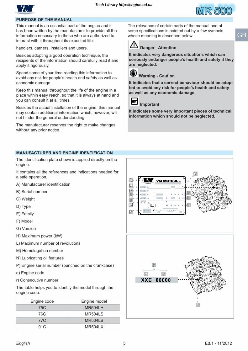
MANUFACTURER AND ENGINE IDENTIFICATIONThe identification plate shown is applied directly on the engine.
It contains all the references and indications needed for a safe operation.
A) Manufacturer identification
B) Serial number
C) Weight
D) Type
E) Family
F) Model
G) Version
H) Maximum power (kW)
L) Maximum number of revolutions
M) Homologation number
N) Lubricating oil features
P) Engine serial number (punched on the crankcase)
q) Engine code
r) Consecutive number
The table helps you to identify the model through the engine code.
Engine code Engine model7�C MR�0�LH76C MR�0�LS77C MR�0�LB91C MR�0�LX
The relevance of certain parts of the manual and of some specifications is pointed out by a few symbols whose meaning is described below.
Danger - AttentionIt indicates very dangerous situations which can seriously endanger people’s health and safety if they are neglected.
Warning - CautionIt indicates that a correct behaviour should be adop-ted to avoid any risk for people’s health and safety as well as any economic damage.
ImportantIt indicates some very important pieces of technical information which should not be neglected.
Tech Library http://engine.od.ua

MR 500
Ed.1 - 11/20126
MR 500
English
GB
PROCEDURE TO REQUEST TECHNICAL ASSISTANCE
WARRANTY CONDITIONS
ATTACHED DOCUMENTATION
Please state the data contained in the identification plate, the serial number, approximate hours of opera-tion and the type of defect detected in every request of technical assistance for the engine.
In case of need, please apply to the manufacturer’s Te-chnical Assistance Service or to an authorised workshop (See attached documentation “Address booklet of assi-stance and spare part centres”).
The warranty conditions are stated in the attached docu-mentation (See “Warranty sheet”).
The stated documentation is supplied to the client along with this manual.
– Wiring diagrams
– Address booklet of assistance and spare part centres
– Warranty sheet
Further information are available in the website:
www.vmmotori.it, in the “Contacts – Request Info” sec-tion.
Tech Library http://engine.od.ua
MR 500MR 500
Ed.1 - 11/20127
MR 500
English
GB
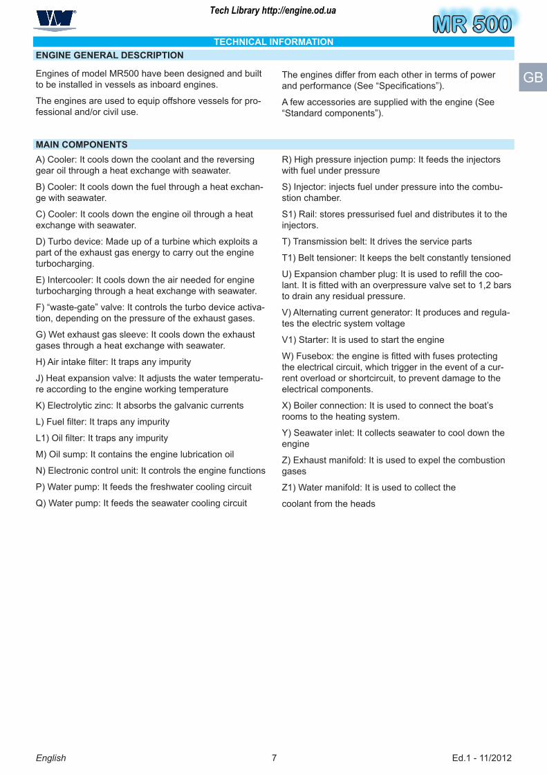
TECHNICAL INFORMATIONENGINE GENERAL DESCRIPTION
Engines of model MR�00 have been designed and built to be installed in vessels as inboard engines.
The engines are used to equip offshore vessels for pro-fessional and/or civil use.
The engines differ from each other in terms of power and performance (See “Specifications”).
A few accessories are supplied with the engine (See “Standard components”).
A) Cooler: It cools down the coolant and the reversing gear oil through a heat exchange with seawater.
B) Cooler: It cools down the fuel through a heat exchan-ge with seawater.
C) Cooler: It cools down the engine oil through a heat exchange with seawater.
D) Turbo device: Made up of a turbine which exploits a part of the exhaust gas energy to carry out the engine turbocharging.
E) Intercooler: It cools down the air needed for engine turbocharging through a heat exchange with seawater.
F) “waste-gate” valve: It controls the turbo device activa-tion, depending on the pressure of the exhaust gases.
G) Wet exhaust gas sleeve: It cools down the exhaust gases through a heat exchange with seawater.
H) Air intake filter: It traps any impurity
J) Heat expansion valve: It adjusts the water temperatu-re according to the engine working temperature
K) Electrolytic zinc: It absorbs the galvanic currents
L) Fuel filter: It traps any impurity
L1) Oil filter: It traps any impurity
M) Oil sump: It contains the engine lubrication oil
N) Electronic control unit: It controls the engine functions
P) Water pump: It feeds the freshwater cooling circuit
Q) Water pump: It feeds the seawater cooling circuit
R) High pressure injection pump: It feeds the injectors with fuel under pressure
S) Injector: injects fuel under pressure into the combu-stion chamber.
S1) Rail: stores pressurised fuel and distributes it to the injectors.
T) Transmission belt: It drives the service parts
T1) Belt tensioner: It keeps the belt constantly tensioned
U) Expansion chamber plug: It is used to refill the coo-lant. It is fitted with an overpressure valve set to 1,2 bars to drain any residual pressure.
V) Alternating current generator: It produces and regula-tes the electric system voltage
V1) Starter: It is used to start the engine
W) Fusebox: the engine is fitted with fuses protecting the electrical circuit, which trigger in the event of a cur-rent overload or shortcircuit, to prevent damage to the electrical components.
X) Boiler connection: It is used to connect the boat’s rooms to the heating system.
Y) Seawater inlet: It collects seawater to cool down the engine
Z) Exhaust manifold: It is used to expel the combustion gases
Z1) Water manifold: It is used to collect the
coolant from the heads
MAIN COMPONENTS
Tech Library http://engine.od.ua

MR 500
Ed.1 - 11/2012�
MR 500
English
GBFuses W
Injectors S
Boiler connec-tion X
Expansion tank plug U
Exhaust manifold Z
Heat exchanger C
Air Filter H
Electrolytic zinc K
Turbo D
Riser G
Boiler connection XThermostatic coolant
valve J
Heat exchanger ACoolant manifold Z1
Alternator V
Oil filter L1
Injection high pressure pump R
Belt tensioner T1
Oil pan M
Belt T
Coolant pump P
Sea water pump Q
Sea water inlet Y
Fuel heat exchanger B
Fuel filter L
Starter motor V1
Engine ECU N
Electrolytic zinc K
Intercooler E
Rail S1
Waste gate valve F
Tech Library http://engine.od.ua

MR 500MR 500
Ed.1 - 11/20129
MR 500
English
GB
ENGINE ACCESSORIESThe following accessories are supplied with the engine
1) Oil change pump
2) Control board
SPECIFICATIONSThese technical data and specifications refer exclusively to standard VM MOTORI S.P.A. engines.
�) Extension cable connecting control board/engine wiring
�) Fuses
DIMENSIONSA mm 60�B mm 610C mm 720
GENERAL DATACycle Four stroke dieselTotal displacement litres 1,991No. cylinders no. �Bore and stroke mm ��x92Compression ratio 17,�:1Air system Turbocharged and inter-cooled circuit
(Dry) air filterCoolant system Water circuitHeat exchanger Water/WaterCrankshaft rotation Anticlockwise (observing the engine from the hand-
wheel side)Combustion sequence 1-�-�-2Engine timing No. 1 camshaft (SOHC), No. � valves per cylinder and
hydraulic tappetsDrive belt timing system
Minimum idling speed (standard engine) rpm 700Dry shipping weight of engine Kg 2�0Maximum permanent lengthwise inclination (with handwheel up)
20°
Maximum permanent lengthwise inclination (with handwheel down)
1�°
Maximum permanent crosswise inclination 2�°
Tech Library http://engine.od.ua

MR 500
Ed.1 - 11/201210
MR 500
English
GB
POWER AND TORQUEMaximum power kW (CV) @ rpm LB 11� HP (��.6 Kw) @ �000 rpm
LS 1�0 HP (9�.6 Kw) @ �000 rpm
LH 1�0 HP (110 Kw) @ �000 rpm
LX 170 HP (12� Kw) @ �000 rpmMaximum torque Nm (kgm) @ rpm �10 Nm @ 2�00 rpm (LB)
�10 Nm @ 2600 rpm (LS/LH/LX)CONSUMPTION AT MAXIMUM POWER
Specific oil consumption g/CVh /FUEL SYSTEM
Injection type Common Rail direct injectionFuel type The engine has been designed to be powered by standard fuels available on the
European market (according to specifications DIN EN 590). If it is to be powered by BIODIESEL fuels (according to specifications UNI EN14214), it can be mixed, up to �%, with fuel available on the European market (according to regulation DIN EN �90).
Important: Do not use fuels with specifications other than those indi-cated.
Fuel supply Gear pump integrated in high pressure injection pumpInjector supply High pressure injection pump
LUBRICATION SYSTEMType of lubrication Lubrificazione forzataCircuit fuel supply Rotor pumpOil change including filter (standard sump)
litres �,2
Oil quantity at minimum level (standard sump)
litres �,2
Oil quantity at maximum level (standard sump)
litres �,2
Oil pressure at minimum speed (with started engine)
bar 1 - �
Alarm for oil pressure too low bar 0,�Oil cooling Oil/water heat exchanger
FRESH WATER COOLING SYSTEMTotal capacity of the cooling circuit
litres 7,7
Setting pressure of the expansion tank plug
bar 1,2
Coolant 50% demineralised or distilled water and 50% Petronas Paraflu Up, red colour (protective radiator fluid with monoethylene glycol and organic inhibitor formula-tion complying with AST M D ��06 type 1 Standards)
Tech Library http://engine.od.ua
MR 500MR 500
Ed.1 - 11/201211
MR 500
English
GB
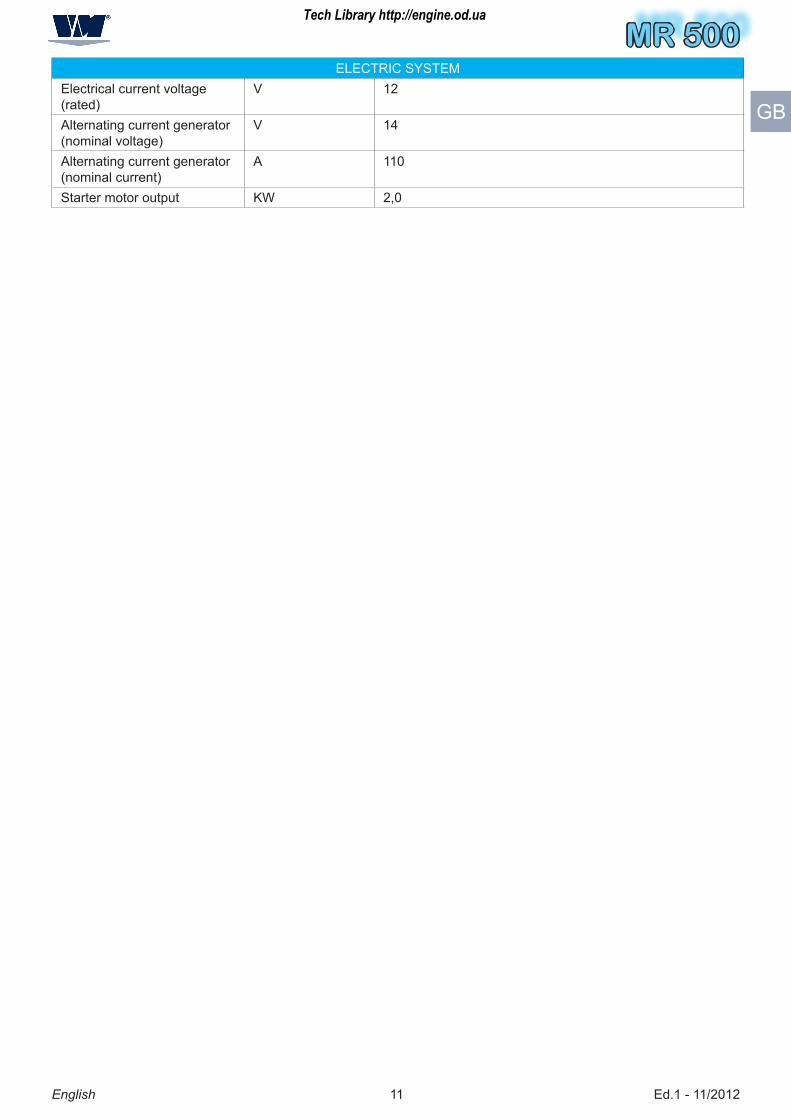
ELECTRIC SYSTEMElectrical current voltage (rated)
V 12
Alternating current generator (nominal voltage)
V 1�
Alternating current generator (nominal current)
A 110
Starter motor output KW 2,0
Tech Library http://engine.od.ua

MR 500
Ed.1 - 11/201212
MR 500
English
GB
SAFETY INFORMATIONSAFETY RULES
– During the design and construction phases, the Ma-nufacturer paid special attention to the aspects which are liable to cause any risk for the safety and health of people interacting with the engine. Besides complying with the relevant legislation in force, he followed all the “rules for a good construction technique”. The purpose of this information is making users aware of the need to pay the utmost attention to prevent any risk. Caution is however imperative. Safety also depends on all the operators who interact with the engine.
– Read carefully the instructions contained in the manual supplied and those applied on the engine, in particular follow those concerning safety. Spend some of your time reading the instructions to avoid unpleasant accidents.
– Pay attention to the meaning of the symbols in the applied plates; their shape and colour have a specific meaning related to safety. Keep them visible and follow the stated information.
– Use the engine only for the tasks authorised by the manufacturer and do not tamper with any device to achieve a different performance from the intended one.
– The staff carrying out any type of intervention throu-ghout the life of the engine should have precise tech-nical skills, specific abilities and experiences acquired and acknowledged in this sector. The lack of these requirements may cause damages to people’s safety and health.
– All the installation phases should have been taken into account since the development of the initial project. The designer has to observe with the engine fixing points and the general indications provided by the manufactu-rer.
– Carry out the handling of the engine in compliance with the information stated directly on the engine, on the packaging and in the operating instructions supplied by the manufacturer.
– When lifting or transporting unpacked engines use means of appropriate load capacity which must be pro-perly anchored.
– When lifting and transporting packaged engines, means of appropriate load capacity as stated on the packaging itself.
– Before carrying out other transfers, create the condi-tions required to guarantee stability and to prevent any engine part from being damaged.
– Before starting the installation, the installer has to implement a “safety plan” and to follow the designer’s indications. Do not make changes to the engine compo-nents for any reason.
– It is necessary to make sure that the installation area is fitted with all intake, fuel supply and exhaust connec-tions.
– The manufacturer cannot be held responsible for any damage resulting from the misuse of the engine, from the failure to follow the indications contained in this manual and from any tampering with or change made without the manufacturer’s authorization.
– If appropriate, before using the engine for the first time, after gathering all the necessary information, simulate a few trial manoeuvres to identify the controls and their main functions, especially those related with starting and stop operations.
– Do not operate the engine in a closed and insuffi-ciently ventilated environment; the exhaust fumes are harmful and can have serious consequences on peo-ple’s health.
– Do not keep using the engine if anomalies are de-tected and in particular if suspect vibrations occur.
– In case of anomaly, stop immediately the engine or reduce the speed as much as possible and reach the closest assistance centre.
– Start again the engine only when the normal operating conditions have been restored.
– Unless otherwise stated, all interventions should be carried out when the engine has been stopped, cooled down and the ignition key has been removed. Those authorized to carry out these interventions should follow all the precautions needed to guarantee the safety of the people involved, in compliance with the requiremen-ts laid down in the applicable legislation regarding safety at the workplace.
– Keep the equipment as much efficient as possible and carry out the scheduled maintenance operations esta-blished by the manufacturer. A good maintenance will ensure the highest performance, a longer working lifeti-me and a constant compliance with safety requirements.
– Replace any worn part with original spare parts. Use the oils and greases recommended by the manufacturer. All this will ensure the engine good operation and the prescribed safety level.
– Do not throw away any polluting material in the envi-ronment. Carry out their disposal in compliance with the relevant legislation in force.
– During all maintenance operations always use the individual protection clothing and/or devices indicated in the operating instructions supplied by the manufacturer and those provided by the applicable legislation concer-ning safety at the workplace.
– All maintenance operations should be carried out by using suitable and efficient equipment and tools.
Tech Library http://engine.od.ua
MR 500MR 500
Ed.1 - 11/20121�
MR 500
English
GB
SAFETY RULES FOR THE ENVIRONMENTAL IMPACT
RESIDUAL RISKS
During the design and construction phases, the Ma-nufacturer paid special attention to the aspects which are liable to cause any risk for the safety and health of people interacting with the engine.
Despite this, some potential and hidden risks still exist.
Danger of injuring your arms
Do not put your hands inside any moving part.
Danger of being burnt
Pay attention to hot surfaces
Each organization is responsible for implementing pro-cedures aimed at identifying, evaluating and controlling the environmental impact of its own activities (products, services, etc.).
The procedures to be followed to identify any signifi-cant environmental impact should take into account the following factors:
– Emissions in the atmosphere
– Discharged liquids
– Waste disposal
– Soil contamination
– Use of raw materials and natural resources.
– Local problems related to the environmental impact.
In order to reduce the environmental impact, the ma-nufacturer provides below a few indications to be taken into account by all those who will interact with the engi-ne throughout its expected life.
– All packaging components should be disposed of in accordance with the legislation in force in the country where disposal takes place.
– When installing the engine, ensure a suitable air re-newal in the environment to protect the operators from a high concentration of harmful substances.
– During operation and maintenance, do not throw away polluting products (oils, greases, etc) in the environment and carry out the differentiated waste disposal according to the composition of the different materials and in com-pliance with the legislation in force. Electric and electro-nic components should be carried out as special waste.
– Keep the exhaust pipelines efficient to limit the noise level of the engine and to reduce atmospheric pollution.
– While decommissioning the engine, divide all the com-ponents depending on their chemical composition and dispose of them accordingly.
Tech Library http://engine.od.ua

MR 500
Ed.1 - 11/20121�
MR 500
English
GB
HANDLING AND INSTALLATION INFORMATIONRECOMMENDATIONS FOR HANDLING AND INSTALLATION
PACKAGING AND TRANSPORT
Means of transport
Lifting means
packaging with wooden case packaging with cardboard box packaging with cellophane
Carry out handling and installation following the informa-tion provided by the manufacturer and stated directly on the packaging and operating instructions.
T hose authorized to carry out these operations should prepare, if necessary, a “safety plan” to protect and the safety of people directly involved.
The packaging is also made according to the type of transport chosen to keep sizes as small as possible.
– By road
– By railway
– By sea
– By air
The engine can be transported with different types of packaging according to the destination, the transport system and preset technical-commercial specifications.
Tech Library http://engine.od.ua
MR 500MR 500
Ed.1 - 11/20121�
MR 500
English
GB
supports B
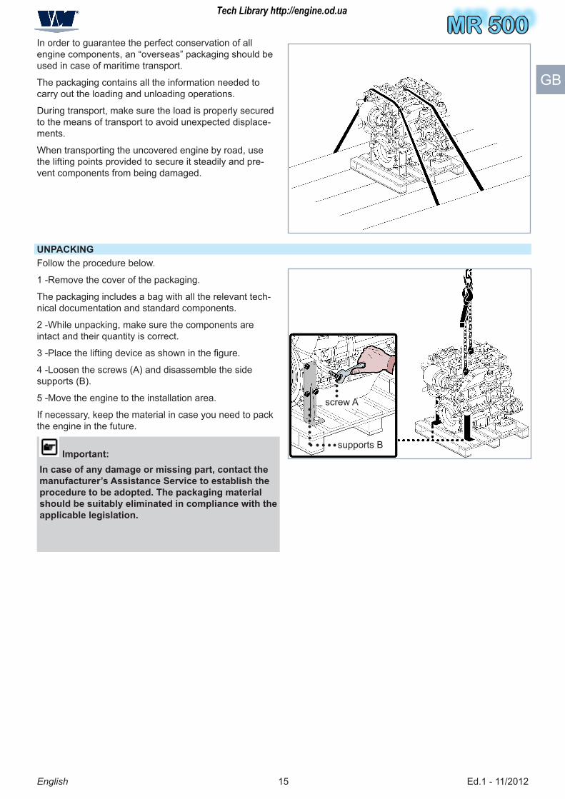
UNPACKING
screw A
In order to guarantee the perfect conservation of all engine components, an “overseas” packaging should be used in case of maritime transport.
The packaging contains all the information needed to carry out the loading and unloading operations.
During transport, make sure the load is properly secured to the means of transport to avoid unexpected displace-ments.
When transporting the uncovered engine by road, use the lifting points provided to secure it steadily and pre-vent components from being damaged.
Follow the procedure below.
1 -Remove the cover of the packaging.
The packaging includes a bag with all the relevant tech-nical documentation and standard components.
2 -While unpacking, make sure the components are intact and their quantity is correct.
3 -Place the lifting device as shown in the figure.
� -Loosen the screws (A) and disassemble the side supports (B).
� -Move the engine to the installation area.
If necessary, keep the material in case you need to pack the engine in the future.
Important:In case of any damage or missing part, contact the manufacturer’s Assistance Service to establish the procedure to be adopted. The packaging material should be suitably eliminated in compliance with the applicable legislation.
Tech Library http://engine.od.ua

MR 500
Ed.1 - 11/201216
MR 500
English
GB
HANDLING AND LIFTINGSecure the engine with a lifting device (lifting beam) of appropriate capacity.
Warning - CautionThe angle formed by the lifting device chains must not exceed 5°, as shown in the figure.
Hook the lifting device to the fixing points as shown in the figure.
Before carrying out the lifting, identify the barycentre position of the load.
Warning - CautionThe brackets of the fixing points have been designed to lift the engine only without any additional weight. Do not lift the engine using a different procedure from the prescribed one; otherwise, the warranty for damages will be invalidated.
Tech Library http://engine.od.ua
MR 500MR 500
Ed.1 - 11/201217
MR 500
English
GB
ENGINE STORAGE
If the engine is left idle for prolonged periods, check the possible conditions of conservation in relation to the storage area and the type of packaging.
Avoid any environment exposed to dampness or to the inclemency of weather.
The manufacturer supplies the engine with a protection treatment which is valid for 6 months from the delivery date.
Warning - Caution:
The staff carrying out any type of intervention throu-ghout the life of the engine should have precise technical skills, specific abilities and experiences acquired and acknowledged in this sector. The lack of these requirements may cause damages to peo-ple’s safety and health.
VM Motori recommends that this protection proce-dure is only carried out by VM-authorised person-nel.
Important:
– All packaging components should be disposed of in accordance with the legislation in force in the country where disposal takes place.
The protection procedure is only considered complete when all the following tasks have been performed:
1) protection against external corrosion
2) protection against internal corrosion
�) packaging and storage
This procedure is valid for the following engine situa-tions:
• on a vehicle
• on a pallet
For engines on pallets, it is necessary to install the fol-lowing accessories for engine start-up:
• battery
• fuel tank
• cooling radiator (for liquid-cooled engines only)
• command belt for the alternating current generator
• command belt for the water pump (for liquid-cooled engines only)
1) EXTERNAL PROTECTION
UNPAINTED SURFACES: the unpainted metal compo-nents and surfaces (for instance the engine handwheel) must be protected with “FL MECA FLUID / P11�V” anticorrosion oil.
RUBBER COMPONENTS: unpainted manifolds and pipes must be protected with talcum powder. Check the tightening of the relative fixing clips.
DRIVE BELTS: after applying the internal protection, remove the belts and put them into storage. Protect the surfaces of the metal pulleys with “FL MECA FLUID / P11�V” spray.
ENGINE OPENINGS: Seal all the engine openings, including the exhaust. Use cardboard, plywood or metal covers, making sure they do not leave behind any fragments of material. All the engine openings (e.g. air suction ducts or turbocharger air inlet) must be protected with covers or guards to prevent the entry of solids, liquids or dusts that delay the evaporation of the anticorro sion agents. Apply plugs to the fuel inlet and outlet pipes of the injection system.
BATTERY: Disconnect the battery. When it is fully char-ged, store it in a safe place. Before doing this, protect the terminals against corrosion by applying an anti-rust spray
2) INTERNAL PROTECTION
COMBUSTION CHAMBER: Remove the heating glowplugs from the head, check the piston is in its lowest stroke position (lower standstill point), then spray with Petronas PROT �0 M protective oil. Repeat the operation for the other cylinders, then reinstall the glowplugs.
TURBOCHARGER: Remove the inlet plug from the pipe that delivers oil to the turbocharger, and fill with Petro-nas PROT �0 M protective oil. Replace the inlet plug, applying the correct tightening torque.
ELECTRIC COMPONENTS: Apply anticorrosion spray to the electric contacts and connectors.
AIR SUCTION SYSTEM: check the air filter is in good condition, and no foreign bodies/liquids are present:
If the air filter is damaged, replace it
If there are any foreign bodies, remove them
•
•
Tech Library http://engine.od.ua
MR 500
Ed.1 - 11/20121�
MR 500
English
GB
LUBRICATION SYSTEM: this procedure must be carried out together with the injection system protection procedure.
• Using the oil dipstick and check whether there is engi-ne oil in the sump.
• Drain the oil from the sump.
• Fill the engine with Petronas PROT �0 M protective oil.
• Check the coolant level (for water-cooled engines only). The coolant mixture must be �0% demineralised or distilled water and 50% Petronas Paraflu Up (protec-tive radiator fluid with monoethylene glycol and organic inhibitor formulation complying with ASTM D ��06 type 1 Standards).
• Start up the engine and run it until it reaches the right temperature for water-cooled engines (about 70°- �0°C); for air-cooled engines, run the engine for about 20 (twenty) minutes.
• With the engine up to temperature, carry on for about � minutes so that the system components are lubricated.
• Switch off the engine and wait for it to cool down.
• Drain the oil from the sump.
• Drain off the coolant.
• Check for any fluid leakage (and make any necessary repairs).
• Disconnect the engine from all the components used for the test.
INJECTION SYSTEM: this procedure must be carried out together with the lubrication system protection pro-cedure.
• Make sure there are no deposits or sediments in the fuel tank.
• Prepare a mixture of diesel fuel complying with the DIN EN 590 specifications, and Petronas DIESEL TMF PLUS additive. The ratio must be at least 1:�00 (1 litre of additive to �00 litres of fuel). If you use Biodiesel (complying with the UNI EN 14214 specifications), it must be mixed with diesel fuel up to �%;
Important:
VM Motori, however, recommends the use of diesel without Biodiesel.
Important:
The use of any other fuel is forbidden.
• Fill the tank with this fuel mixture.
• Where relevant, check there is no interference between the radiator fan blades and the relative air duct.
Start up the engine and run it until it reaches the right temperature for water-cooled engines (about 70°- �0°C); for air-cooled engines, run the engine for about 20 (twenty) minutes.
• Drain the fuel tank.
• Check for any fluid leakage (and make any necessary repairs).
• Switch off the engine and wait for it to cool down.
SEAWATER SYSTEM (for marine engines and on-board auxiliary units only): this procedure must be carried out together with the injection system protection procedure.
• Connect the seawater intake of the seawater pump to an auxiliary tank containing a mixture of �0% freshwater and 60% Petronas Paraflu Up (protective radiator fluid with monoethylene glycol and organic inhibitor formu-lation complying with ASTM D ��06 type 1 Standards), making sure it seeps out from the drainage point.
• Check for any fluid leakage (and make any necessary repairs).
• Switch off the engine and wait for it to cool down.
• Disconnect the engine from all the components used for the test
Tech Library http://engine.od.ua

MR 500MR 500
Ed.1 - 11/201219
MR 500
English
GB
3) STORAGE CONDITIONS
- Engines on pallets
After applying the anticorrosion protection, the engine must be placed in a dry, well-ventilated environment and ade-quately covered. The covering must be applied in such a way that air can circulate around the engine, preventing the formation of condensation.
- Engines on vehicles
The vehicle must be stored so as to minimise exposure to atmospheric agents
START-UP
- Engines on pallets
Remove the covers and protective elements applied to the engine openings (for instance, air suction ducts or turbo-charger air inlet, exhaust gas ducts or turbocharger guard).
Check there is no damage to the external engine components; make any necessary repairs.
Clean the throats of the metal belt pulleys, using a suitable solvent. Install the service belts
Check the rubber tubes and manifolds are in good condition, and check the tightening of the relative fixing clips; if they are damaged, replace them.
All surfaces and components protected with “FL MECAFLUID / P11� V” protective oil can be cleaned with a suitable solvent.
Check the level of the fluids: engine oil and coolant. Top up if necessary.
- Engines on vehicles
Check there is no damage to the external engine components; make any necessary repairs.
Clean the throats of the metal belt pulleys, using a suitable solvent. Install the service belts.
Check the rubber tubes and manifolds are in good condition, and check the tightening of the relative fixing clips; if they are damaged, replace them.
Important:
Nothing needs to be done to remove the internal protection (either for engines on pallets or on vehicles).
INSTALLATION DESIGN
In order to ensure the highest performance while pro-tecting people, the product itself and the environment, a full project has to be developed before carrying out the installation.
Important:The design phase should take into account the te-chnical data of the engine (see”Technical data”) and all the risks which may occur during its expected lifetime, from installation to disposal. During the design and installation phase, it is a good idea to consult the installation manual drawn up by VM MOTORI S.P.A. as this contains the installation guidelines.
Further information are available in the website: www.vmmotori.it, in the “Contacts – Request Info” section.
Tech Library http://engine.od.ua

MR 500
Ed.1 - 11/201220
MR 500
A
B
D
C
E
F
G
H L
M
N
English
GB
OPERATING INFORMATION
RECOMMENDATIONS FOR USE AND OPERATION
CONTROL BOARD DESCRIPTION
The engine has been designed and manufactured to satisfy all the operating conditions indicated by the manu-facturer.
Tampering with any device to achieve a different perfor-mance from the intended one can entail risks for people’s safety and health as well as economic damages.
A) Pressure gauge: It indicates the engine oil pressureB) Warning light (red): It signals that the engine oil pressure is low. When indicator lights up the beeper is triggered.C) Voltmeter: It indicates the battery voltageD) Warning light (red): It signals a malfunction in the alternating current generator or battery. When indicator lights up the beeper is triggered.E) Thermometer: It indicates the temperature of the freshwater coolantF) Warning light (red): It signals that the temperature of the freshwater coolant is too high. When indicator lights up the beeper is triggered.
G) Rev counter and hour counter: It indicates the number of engine revolutions and the actual hours of functioningH) Digital display: in the presence of operating malfunc-tions, this displays the values detected by the instrumen-ts, the error identification codes and the relevant descrip-tion.L) Button: used to show the malfunctions on display in sequence.M) Key switch: used to turn the power supply to the control panel on and off.N) Pushbutton: It is used to start the engine.
Tech Library http://engine.od.ua

MR 500MR 500
Ed.1 - 11/201221
MR 500
English
GB
RECOMMENDATIONS FOR USEThe engine is delivered by the factory in the running order. However, during operation the following indications should be observed:1 -During running-in (first 50 working hours) and throu-ghout the engine lifetime, carry out the maintenance in compliance with the intervals established by the manufac-turer (see “Engine maintenance”2 -If the engine is not used regularly, start it after each month of inactivity and run it at minimum speed until the operating temperature (70÷�0°C) is reached.� -Avoid using the engine at the highest speed for prolon-ged periods during running- in.4 -When starting the engine for the first time, run it at no-load for a few minutes and make sure that the oil pressure value matches the one stated in the table (see “Specifications” - “Lubrication circuit”).
� -Properly pre-heat the engine when using it at low tem-peratures. When usingthe engine at low temperatures (lower than -10°C), fill it with winter-type fuel.6 -Use oils and lubricants with suitable features (viscosity grade, specifications and operating temperature) (see “Recommended lubricants”).7 -If the alarm signal, which can be acoustic and/or visible on the control panel according to the type of installation, is triggered while the engine is running, the electronic management system may switch the engine to emergen-cy operation, with automatic restriction of performance levels..
ImportantIf the alarm signal is triggered, contact a VM MOTORI S.P.A. service centre.
OPERATING THE ENGINE UNDER SPECIFIC CONDITIONS
The engine performance is affected by fuel temperature, the temperature and relative humidity of incoming air and altitude.When using the engine at high altitudes and high air and fuel temperatures, the output is reduced.For further information contact a VM MOTORI S.P.A. assistance centre.
Tech Library http://engine.od.ua
MR 500
Ed.1 - 11/201222
MR 500
English
GB
ENGINE IGNITION AND TURNING OFF
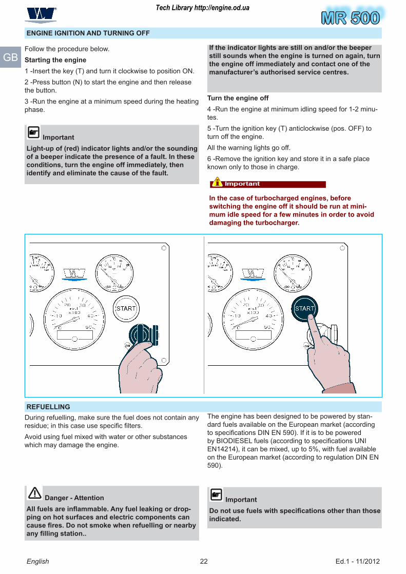
Follow the procedure below.Starting the engine1 -Insert the key (T) and turn it clockwise to position ON.2 -Press button (N) to start the engine and then release the button.� -Run the engine at a minimum speed during the heating phase.
ImportantLight-up of (red) indicator lights and/or the sounding of a beeper indicate the presence of a fault. In these conditions, turn the engine off immediately, then identify and eliminate the cause of the fault.
Turn the engine off� -Run the engine at minimum idling speed for 1-2 minu-tes.� -Turn the ignition key (T) anticlockwise (pos. OFF) to turn off the engine.All the warning lights go off.6 -Remove the ignition key and store it in a safe place known only to those in charge.
In the case of turbocharged engines, before switching the engine off it should be run at mini-mum idle speed for a few minutes in order to avoid damaging the turbocharger.
If the indicator lights are still on and/or the beeper still sounds when the engine is turned on again, turn the engine off immediately and contact one of the manufacturer’s authorised service centres.
REFUELLINGDuring refuelling, make sure the fuel does not contain any residue; in this case use specific filters.Avoid using fuel mixed with water or other substances which may damage the engine.
The engine has been designed to be powered by stan-dard fuels available on the European market (according to specifications DIN EN 590). If it is to be powered by BIODIESEL fuels (according to specifications UNI EN1�21�), it can be mixed, up to �%, with fuel available on the European market (according to regulation DIN EN �90).
ImportantDo not use fuels with specifications other than those indicated.
Danger - AttentionAll fuels are inflammable. Any fuel leaking or drop-ping on hot surfaces and electric components can cause fires. Do not smoke when refuelling or nearby any filling station..
Tech Library http://engine.od.ua

MR 500MR 500
Ed.1 - 11/20122�
MR 500
English
GB
MAINTENANCE INFORMATION
RECOMMENDATIONS FOR MAINTENANCE
Keep the equipment as much efficient as possible and carry out the scheduled maintenance operations esta-blished by the manufacturer.A good maintenance will ensure the highest performance, a longer operating lifetime and a constant compliance with safety requirements.
Warning - CautionUnless otherwise stated, all interventions should be carried out when the engine has been stopped, coo-led down and the ignition key has been removed.Those authorized to carry out these interventions should follow all the precautions needed to guaran-tee the safety of the people involved, in compliance with the requirements laid down in the applicable legislation concerning safety at the workplace..
ENGINE MAINTENANCE
The maintenance operations are subdivided into:– Maintenance during running-in (first 50 hours)– Routine maintenance (after running-in) The frequen-cy stated in the “ routine maintenance” table should be applied to engines which are used regularly.Some lubricants or components lose their characteristics over time even if the engine is left idle for long periods; therefore, maintenance intervals should be established considering that these parts need to be replaced not only on the basis of their hours of operation but of ageing as well.
Maintenance during running-in table (first 50 hours)
Frequency(5) Component Type of inter-vention
Intervention procedures Reference
Every 10 hours
Engine oil Level control Top up, if necessary See “Engine oil level control”
Coolant Level control Top up, if necessary See “Engine coolant level check”
After the first 50 hours (at the end of running- in)
Engine oil (1) Replacement See “Engine oil change”
Oil filter (2) Replacement See “Oil filter cartridge replacement”
The approximate maximum time during which the che-mical-physical characteristics of a few components or lubricants are maintained is stated below.– 1 year – Lubricant oil– 1 year - Fuel filter cartridge– 2 years - Cartridges, air and oil filter– 2 years – Coolant– 2 years – Transmission belt (type POLY-V)
Tech Library http://engine.od.ua

MR 500
Ed.1 - 11/20122�
MR 500
English
GB
Routine maintenance table (after running-in)
Frequency(5)(5) Component Type of inter-Type of inter-vention
InterventionIntervention procedures
Reference
Every 10 hours
Engine oil (1) Level controlLevel control Top up, if necessary
See “Engine oil level control”See “Engine oil level control”
Coolant (�) Level controlLevel control Top up, if necessary
See “Engine coolant level check”
Every 50 hours
Electrolytic zinc
Integrity con-trol
Replace, if necessary
See “Electrolytic zinc replacement”
(1) Even if the engine has not been run for the prescribed period, it is equally necessary to carry out the replacement at least once per year.
(2) Even if the engine has not been run for the prescribed period, it is equally necessary to carry out the replacement at least once every 2� months.
(�) If the engine has not been in operation for the length of time indicated, the heat exchangers must still be cleaned at least once every � years.
(�) If an hour counter is not available, the frequency of the interventions should be calculated on the basis of a calendar day: one calendar day corresponds to 12 hours of operation.
Every100 hours
Seawater pump impeller
Integrity control Replace, if necessary
Every 300 hours
Transmission belt (2)
ReplacementReplacement See “Belt replacement”
Seawater pump impel-ler(1)
ReplacementReplacement Apply to an authorised workshop
Engine oil (1) Replacement See “Engine oil change” Oil filter (2) Replace the
cartridge See “Oil filter cartridge replacement”
Air filter (2) ReplacementReplacement See “Inlet air filter replacement” Fuel filter(1) ReplacementReplacement See “Fuel filter replacement” Fuel circuit unions
Check tighte-ning
See “Control screw tightening and union sealing”
Electrolytic zinc
ReplacementReplacement See “Electrolytic zinc replacement”
Every 500 hours
Heat ex-changers (en-gine oil, fresh water) (�)
Cleaning Apply to an authorised workshop
Intercooler(�) Cleaning Apply to an authorised workshop Every 600 hours
Coolant (�) Replace See “Coolant replacement”
Tech Library http://engine.od.ua

MR 500MR 500
Ed.1 - 11/20122�
MR 500
English
GB
PERIODIC MAINTENANCE OPERATION RECORD SHEET
ImportantFor each maintenance operation, fill in the sheet, so as to keep a trace of the operations performed and the-refore establish the most suitable methods for future operations.Date Hrs (1) Type of maintenance performed Signature and stamp of workshop
(1) Indicate the total number of working hours.
Tech Library http://engine.od.ua
MR 500
Ed.1 - 11/201226
MR 500
English
GB
(1) Indicate the total number of working hours.
Date Hrs (1) Type of maintenance performed Signature and stamp of workshop
Tech Library http://engine.od.ua
MR 500MR 500
Ed.1 - 11/201227
MR 500
English
GB
(1) Indicate the total number of working hours.
Date Hrs (1) Type of maintenance performed Signature and stamp of workshop
Tech Library http://engine.od.ua

MR 500
Ed.1 - 11/20122�
MR 500
English
GB
(1) Indicate the total number of working hours.
Date Hrs (1) Type of maintenance performed Signature and stamp of workshop
Tech Library http://engine.od.ua

MR 500MR 500
Ed.1 - 11/201229
MR 500
English
GB
(1) Indicate the total number of working hours.
Date Hrs (1) Type of maintenance performed Signature and stamp of workshop
Tech Library http://engine.od.ua
MR 500
Ed.1 - 11/2012�0
MR 500
English
GB
MAINTENANCE WHEN THE ENGINE IS LEFT IDLE
If the boat where the engine is installed is left idle for a long time, it is necessary to carry out some maintenance work to preserve the engine’s maximum efficiency condi-tions.If the engine is not used for short periods of time, carry out the following interventions:1 -Make sure the electric contacts are working properly and, if necessary, protect them with an anti-oxidant spray.2 -Check the charge of the battery and the liquid level.� -If necessary, carry out the scheduled maintenance work (see “Engine maintenance”).
It is advisable to start the engine bringing it to the operating temperature (70÷80°C) at least once per month.The engine must be started once per month if it is installed for emergency purposes.If the engine is left idle for prolonged periods, carry out the engine protective treatment to guarantee its efficiency for 6 months and to avoid continuous con-trol and maintenance interventions. If the engine is not used for a further period of time, check the need to repeat the protective treatment for other 6 months (see “Engine Storage”).
MAINTENANCE IN CASE OF ENGINE INACTIVITYAfter a period of inactivity, it is necessary to carry out a few maintenance interventions before starting the engine again to ensure its maximum efficiency conditions.– Check the charge of the battery and the liquid level.– Make sure the electric contacts are intact and properly working.– Carry out the operation diagnosis of the engine (see “Diagnosis of failures”).– Check the oil level, and, if necessary, top up or replace it according to the established intervals (see “Routine maintenance table (after running-in)”).– Replace the oil filter according to the established inter-vals (see “Routine maintenance table (after running-in)”).– Check the coolant level, and if necessary, top up or replace it according to the established intervals (see “Routine maintenance table (after running-in)”).– Replace the fuel filter according to the established inter-vals (see “Routine maintenance table (after running-in)”).– Replace the air filter according to the established inter-vals (see “Routine maintenance table (after running-in)”).
– Tension again the transmission belt (see “Method for tightening or loosening the belt”).– Check the tightening of the hydraulic unions (see “Con-trol screw tightening and union sealing”).– Check the integrity of the impeller of the seawater pump (see “Routine maintenance table (after running-in)”).– Check the integrity of the electrolytic zinc (see “Routine maintenance table (after running-in)”)– Use a cloth soaked in a degreasing product to remove the external protective treatment.– Start the engine and run it at minimum speed for a few minutes (see “Engine ignition and turning off”).– If no anomalies are detected, bring the engine to its operating temperature (70÷�0°C).– Turn off the engine and check again the engine oil and coolant level.
CHECKS AND CONTROLS
The information needed to carry out all maintenance, check and control operations which do not require the replacement of mechanical components are provided below.
Tech Library http://engine.od.ua

MR 500MR 500
Ed.1 - 11/2012�1
MR 500
E
F
L
M
English
GB
CONTROL SCREW TIGHTENING AND UNION SEALING
Follow the procedure below.1 -Start the engine and run it at minimum speed for a few minutes.2 -Run the engine at normal speed until the operating temperature (70÷�0°C) is reached.� -Turn off the engine and let it cool down.
4 -Make sure the fixing screws of the main parts are tightened properly.� -Check the union sealing on the fuel supply circuit.6 -Check the tightening of the clamps.7 -Check any fluid leaks.
Follow the procedure below.1 -Turn off the engine and remove the ignition key.2 -Let the engine cool down adequately to avoid being burnt.� -Prepare a container of appropriate capacity.� -Loosen the screw (E).� -Operate the pump (F) manually to eliminate air from the circuit.6 -Check that a flow of clean fuel containing no air bub-bles is coming out of the bleeder screw (E).7 -Tighten the screw (E).� -Wipe out the fuel residues before starting the engine.
ImportantWhen bleeding the fuel circuit, make sure that you do not drain all the fuel contained in the filter. If you do, remove the filter , fill it with fuel, replace it and bleed again.
FUEL SUPPLY CIRCUIT BLEEDING
Tech Library http://engine.od.ua

MR 500
Ed.1 - 11/2012�2
MR 500
M
A
C
B
English
GB
ENGINE COOLANT LEVEL CHECK
Follow the procedure below.1 -Start the engine and bring it to the operating tempera-ture (70÷�0 °C).2 -Turn off the engine and remove the ignition key.� -Let the engine cool down properly.� -Unscrew the load plug (P).
Warning - CautionOpen the plug gently to drain the pressure.
� -Top up, if necessary, from plug (P). As for the liquid quantity and type, see “Specifications”.
Important The liquid level should be included between the mi-nimum and maximum notches printed on the expan-sion chamber.
METHOD FOR TIGHTENING OR LOOSENING THE BELT
Follow the procedure below.1 -Turn off the engine and remove the ignition key.2 -Let the engine cool down adequately to avoid being burnt.� -Loosen the belt by moving the tensioner (A) until the holes (B) match and block it with pin (C).� -Tension the belt by moving the tensioner (A), remove the pin (C) and release it..
Warning - CautionTo tighten the belt, it must be correctly positioned in the housings on each of the pulleys (see “Belt replacement”).
Tech Library http://engine.od.ua

MR 500MR 500
Ed.1 - 11/2012��
MR 500
M
Q
R
English
GB
Warning - CautionIn the event of oil leaks, check the level periodically to evaluate the extent of the leak. If the amount is excessive, contact one of the manufacturer’s autho-rised service centres.
ImportantDo not throw the oil in the environment but carry out its disposal in compliance with legislation in force in the country where it is used. Use the oils and lubricators recommended by the manufacturer (see “Recommended lubricants”).
ENGINE OIL CHANGE
Follow the procedure below.1 -Turn off the engine and remove the ignition key.2 -Let the engine cool down adequately to avoid being burnt.� -Prepare a container of appropriate capacity. As for the oil quantity, see “Specifications”.� -Unscrew the load plug (M).� -Unscrew the plug (Q).6 -Insert the pump (R) and screw it to pipe.7 -Operate manually the pump to transfer all the oil into the container.� -Pour the new oil until it reaches the correct level on the dipstick (see “Engine oil level control”)9 -Disconnect the pump.10 -Screw again the plug (Q).11 -Screw again the load plug (M).12 -Start the engine and bring it to the operating tempera-ture (70÷�0 °C).1� -Check for any oil leaks1� -Turn off the engine and check the oil level (see “Engi-ne oil level control”).
Tech Library http://engine.od.ua

MR 500
Ed.1 - 11/2012��
MR 500
S
P
max
min
2� mm
English
GB
COOLANT REPLACEMENT
ImportantDo not throw away any polluting material in the envi-ronment. Carry out their disposal in compliance with the relevant legislation in force.
Follow the procedure below.1 -Start the engine and run it at minimum speed for a few minutes.The cooling circuit reaches the operating pressure.2 -Turn off the engine and remove the ignition key.� -Let the engine cool down adequately to avoid being burnt.� -Prepare a container of appropriate capacity.As for the liquid quantity, see “Specifications”.� -Unscrew the plug (S).6 -Let the liquid flow into the container.7 -Screw again the plug (S).� -Unscrew the plug (P).9 -Pour in the new liquid.
ImportantThe coolant level must be as shown in the figure. As for the liquid quantity and type, see “Specifications”.Only use coolants that comply with the manufactu-rer’s specifications.
10 -Screw again the plug (P).11 -Turn the engine on and leave it running at minimum speed for a few minutes until it reaches working speed (70÷�0°C).12 -Turn off the engine and let it cool down properly.1� -Check the coolant level and, if necessary, carry out topping-up (See “Engine coolant level check”).
Tech Library http://engine.od.ua

MR 500MR 500
Ed.1 - 11/2012��
MR 500
P
T
UV
English
GB
SEAWATER CIRCUIT EMPTYING
Follow the procedure below.1 -Prepare a container of appropriate capacity.2 -Unscrew the plug (P1).3 -Let water flow into the container.� -Screw again the plug (P1).
OIL FILTER CARTRIDGE REPLACEMENT
Follow the procedure below.1 -Turn off the engine and remove the ignition key.2 -Let the engine cool down adequately to avoid being burnt.� -Prepare a container to collect any leak.� -Unscrew the cover (T).� -Replace the cartridge (U).6 -Check the conditions of gasket (V) and, if necessary, replace it.7 -Screw up the cap (T).
ImportantTighten the cap to a tightening torque of 25 Nm.
� -Turn the engine on and leave it running at minimum speed for a few minutes until it reaches working speed (70÷�0°C).9 -Check for any oil leaks
Warning - CautionIn the event of oil leaks, check the level periodically to evaluate the extent of the leak. If the amount is excessive, contact one of the manufacturer’s autho-rised service centres.
ImportantDo not throw away any polluting material in the envi-ronment. Carry out their disposal in compliance with the relevant legislation in force.
Tech Library http://engine.od.ua

MR 500
Ed.1 - 11/2012�6
MR 500
Z
English
GBFollow the procedure below.1 -Turn off the engine and remove the ignition key.2 -Let the engine cool down adequately to avoid being burnt.� -Prepare a container to collect any leak.4 -Remove the filter (Z) using the tool provided.5 -Fill the new filter with the fuel from the filter being replaced.6 -Lubricate the gasket of the new filter before mounting it.7 -Fit the new filter using the tool provided.� -Bleed air from the fuel supply circuit (See “Fuel supply circuit bleeding”)9 -Turn the engine on and check for any fuel leaks.
Warning - CautionIn the event of fuel leaks, identify and eliminate the cause. If the problem persists, contact one of the manufacturer’s authorised service centres.
ImportantDo not throw away any polluting material in the envi-ronment. Carry out their disposal in compliance with the relevant legislation in force.
RECOMMENDED LUBRICANTS
The lubricant recommended by VM MOTORI S.P.A. is: Q� HD SPECIAL 10W-�0 for operating temperatures from -20°C to +�0°C..Oils of different brands can be used provided that they have the following features:– Viscosity grade: SAE 10 W - �0– Minimum specifications: ACEA A�/B� API CF
ImportantIt is advisable not to mix oils with different characte-ristics.
Tech Library http://engine.od.ua

MR 500MR 500
Ed.1 - 11/2012�7
MR 500
English
GB
INFORMATION ABOUT FAILURES
TROUBLESHOOTINGThe information below are provided to facilitate the iden-tification and solution of possible anomalies and failures which may occur during operation.Some of these problems can be solved by the user, while
others require specific technical skills or abilities, therefo-re they should be exclusively dealt with by qualified tech-nicians with extensive experience in the specific sector of intervention.
During the ignition phase the control board and the engine
do not start.
Flat battery Recharge or replace battery Fuse “triggered” Reset the fuse (see “Reset fuses”)
The electric cables are discon-nected or they do not guarantee
continuity Check the electric connections
Failure of engine revolution sen-sor
Replace the sensor Apply to an authorised workshop
The engine does not start
Presence of air in the fuel supply circuit
Carry out bleeding (see “Fuel supply circuit bleeding”)
Dirty or faulty injectors Clean or replace injectors Apply to an autho-rised workshop
The injection pump is set incor-rectly or is faulty
Adjust the pump or replace it Apply to an au-thorised workshop
Failure of the start control Replace the start control Apply to an authorised workshop
Fuse “triggered” Reset the fuse (see “Reset fuses”)
The starter motor runs idle
The engine starting relay is not connected correctly or is faulty
Replace the relay Apply to an authorised work-shop
Electromagnet failure Check the starter motor Apply to an authorised workshop
The starter motor is not running
Flat battery Recharge or replace battery Interrupted electric connection Check the electric connections
Worn brushes Replace the worn brushes Apply to an autho-rised workshop
Fuse “triggered” Reset the fuse (see “Reset fuses”)
Problem Cause Remedy
Tech Library http://engine.od.ua

MR 500
Ed.1 - 11/2012��
MR 500
English
GBThe engine stops after
ignition
Presence of air in the fuel supply circuit Carry out bleeding (see “Fuel supply circuit bleeding”)
Clogged fuel filter Replace filter (see “Inlet air filter replace-ment”) The injection pump is set incor-
rectly or is faulty Adjust the pump or replace it Apply to an authorised
workshop The electric cables are discon-nected or they do not guarantee
continuity Check the electric connections
The engine does not reach the operating
speed
Clogged fuel filter Replace filter (see “Fuel filter replacement”) Presence of air in the fuel supply
circuit Carry out bleeding (see “Fuel supply circuit bleeding”)
The injection pump is set incor-rectly or is faulty
Adjust the pump or replace it Apply to an authorised workshop
Dirty or faulty injectors Clean or replace injectors Apply to an authorised workshop
Clogged air filter Clean or replace the filter (see “Inlet air filter replace-ment”)
Overload Reduce the load
Emission of black smoke from the exhaust
pipe
Dirty or faulty injectors Clean or replace injectors Apply to an authorised workshop
The injection pump is set incor-rectly or is faulty
Adjust the pump or replace it Apply to an authorised workshop
Faulty turbocharging turbine Replace the turbine Apply to an authorised workshop
Light emission of white smoke from the exhaust
pipe
Oil level too high Adjust the oil level Worn segments Check compression Apply to an authorised workshop
Worn valve guideways Check wear Apply to an authorised workshop
Problem Cause Remedy
Tech Library http://engine.od.ua
MR 500MR 500
Ed.1 - 11/2012�9
MR 500
English
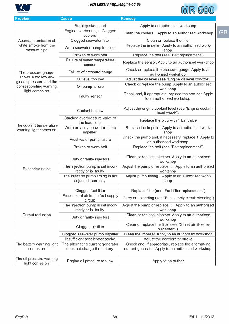
GBAbundant emission of white smoke from the
exhaust pipe
Burnt gasket head Apply to an authorised workshop Engine overheating. Clogged
coolers Clean the coolers. Apply to an authorised workshop
Clogged seawater filter Clean or replace the filter
Worn seawater pump impeller Replace the impeller. Apply to an authorised work-shop
Broken or worn belt Replace the belt (see “Belt replacement”) Failure of water temperature
sensor Replace the sensor. Apply to an authorised workshop
The pressure gauge-shows a too low en-
gineoil pressure and the cor-responding warning
light comes on
Failure of pressure gauge Check or replace the pressure gauge. Apply to an authorised workshop
Oil level too low Adjust the oil level (see “Engine oil level con-trol”)
Oil pump failure Check or replace the pump. Apply to an authorised workshop
Faulty sensor Check and, if appropriate, replace the sen-sor. Apply to an authorised workshop
The coolant temperature warning light comes on
Coolant too low Adjust the engine coolant level (see “Engine coolant level check”)
Stucked overpressure valve of the load plug Replace the plug with 1 bar valve
Worn or faulty seawater pump impeller
Replace the impeller. Apply to an authorised work-shop
Freshwater pump failure Check the pump and, if necessary, replace it. Apply to an authorised workshop
Broken or worn belt Replace the belt (see “Belt replacement”)
Excessive noise
Dirty or faulty injectors Clean or replace injectors. Apply to an authorised workshop
The injection pump is set incor-rectly or is faulty
Adjust the pump or replace it. Apply to an authorised workshop
The injection pump timing is not adjusted correctly
Adjust pump timing. Apply to an authorised work-shop
Output reduction
Clogged fuel filter Replace filter (see “Fuel filter replacement”) Presence of air in the fuel supply
circuit Carry out bleeding (see “Fuel supply circuit bleeding”)
The injection pump is set incor-rectly or is faulty
Adjust the pump or replace it. Apply to an authorised workshop
Dirty or faulty injectors Clean or replace injectors. Apply to an authorised workshop
Clogged air filter Clean or replace the filter (see “SInlet air fil-ter re-placement”)
Clogged seawater pump impeller Clean the impeller. Apply to an authorised workshop Insufficient accelerator stroke Adjust the accelerator stroke
The battery warning light comes on
The alternating current generator does not charge the battery
Check and, if appropriate, replace the alternat-ing current generator. Apply to an authorised workshop
The oil pressure warning light comes on Engine oil pressure too low Apply to an author
Problem Cause Remedy
Tech Library http://engine.od.ua

MR 500
Ed.1 - 11/2012�0
MR 500
A
B
B
English
GB
RESET FUSES
The engine is equipped with safety fuses, which cut out to prevent damage to the electrical components.In the event of malfunctions due to triggering of a fuse, the cause (overload or short circuit current) must be elimi-nated before the fuse is reset.
ImportantIf the problem persists, contact a VM MOTIRI S.P.A. service centre.
Follow the procedure below.1 -Remove all the fuse guards (A).2 -Extract the fuses (B) (one at a time) and check them for damage.
Warning - CautionTo avoid errors when returning the fuses to their places, always check fuses one at a time, replacing them if necessary with a new fuse that has the same characteristics (type, amperage, etc.).
� -When all the fuses have been checked and replaced, fit the respective guards (A) with care.
Tech Library http://engine.od.ua

MR 500MR 500
Ed.1 - 11/2012�1
MR 500
L
H
L
H
H
LD
B F
English
GB
DIAGNOSIS OF FAILURES– The engine is fitted with a self-diagnosis system that allows any operating malfunctions to be identified, by means of indicators (B-D- F) and/or activation of an acou-stic signal.– In the presence of operating malfunctions, the display (H) shows the values detected by the instruments, the error identification codes and the relevant description.– Button (L) serves to show the malfunctions on display in sequence.
Important In the event of malfunctions, turn the engine off immediately, contact one of the manufacturer’s au-thorised service centres and provide them with the information shown on the display.
READING ERROR CODES
In case of malfunction, the display (H) visualises the pre-sence of error codes.In the case of one or more error codes, the display shows the following caption:DTCPhoto 1 represents the presence of 6 malfunctions that have occurred.While holding down the button (L) you can see the first error code “SPN”. Photo 2 represents the presence of the error code SPN 62�.By pressing the button (L) again you can see the errors later.Refer to the table “Error Codes List” to identify the de-scription of the error code.
Photo 1
Photo 2
Tech Library http://engine.od.ua

MR 500
Ed.1 - 11/2012�2
MR 500
English
GBSPN Description0 Immobilizer Key not Correct0 Rail Pressure Signal Offset Control Error0 EGR Radiator Bypass Actuator Malfunction0 NO Description27 Malfunctioning of EGR Exhaust Gas Recirculation Actuator27 Malfunctioning of EGR Exhaust Gas Recirculation Actuator27 Excessive flow of EGR Exhaust Gas Recirculation or Malfunctioning Air Inlet System27 Insufficient flow of EGR Exhaust Gas Recirculation81 DPF Particulate Filter - Low System Efficiency�1 DPF Particulate Filter - Filter Disassembled or Defective�1 DPF Particulate Filter - Non Plausible Differential Pressure�1 DPF Particulate Filter - Active Engine Protection�� Vehicle Speed Sensor Malfunction�� NO Description91 Synchronization Error of Accelerator Pedal Position Sensors91 Accelerator Pedal Position Error - Sensor 191 Accelerator Pedal Position Error - Sensor 291 Position of Accelerator/Brake not plausible91 NO Description97 Actuator Malfunction of Water Level in Gas Oil97 Circuit Malfunction of Water Sensor in Gas Oil97 Detection of Water in Gas Oil100 Alarm for Low Engine Oil Pressure100 Alarm for Critical Engine Oil Pressure100 Signal Error from Engine Oil Pressure Sensor102 Overfeeding Pressure Alarm102 Overfeeding Pressure Sensor Error10� Intake Air Temperature Sensor Alarm10� Intake Air Temperature Sensor Error10� DPF Particulate Filter - Non Plausible Differential Pressure10� Atmospheric Pressure Sensor Error110 Engine water Temperature Alarm110 Engine Water Sensor Error110 Engine water Sensor Malfunction1�1 DPF Particulate Filter - Filter Disassembled or Defective1�1 DPF Particulate Filter - Non Plausible Differential Pressure1�1 DPF Particulate Filter - Active Engine Protection1�1 DPF Particulate Filter - Defective Differential Pressure Sensor1�2 Plausibility Error of Air Flow Signal1�2 Interval Error of Battery Voltage Signal Check1�2 Signal Error of Air Flow of Reference1�7 Rail Pressure Error during Rail Pressure Check from Pressure Regulator1�7 Error of Maximum Pressure Limiting Valve PRV Rail
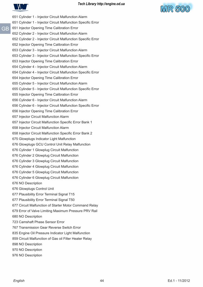
ERROR CODES LIST
Tech Library http://engine.od.ua

MR 500MR 500
Ed.1 - 11/2012��
MR 500
English
GB
16� Error of Rail Pressure Signal16� Battery Voltage Error172 Air Temperature Signal Duty Cycle Error172 NO Description17� Exhaust Gas Temperature Sensor Error - Bank 1 - Position 117� Gas oil Temperature Sensor Error17� Engine Oil Temperature Alarm17� Signal Error from Engine Oil Temperature Sensor177 NO Description190 Engine Overspeed Alarm190 Crankshaft rpm Sensor Error22� Camshaft/Crankshaft Position Sensor Error�1� NO Description�27 Cruise Control Circuit Malfunction�27 NO Description�7� NO Description��1 NO Description�97 Brake Signal Error�9� Clutch Signal Error60� Gearbox Control unit - Neutral gearbox indicator light malfunctioning62� Circuit Malfunction of System indicator light629 Engine ECU - Performance Error of Injection Control Module A629 Engine ECU - Performance Error of Injection Control Module B629 Engine ECU Injector Activation Time Limit Check Error629 Engine ECU RPM Signal Redundancy Check Error629 Engine ECU Internal Communication Error - SPI629 Engine ECU EEPROM Internal Memory Error629 Engine ECU Internal Supply Voltage Error629 Engine ECU Injector Deactivation Redundancy Test Error during Initialization629 Engine ECU Processor Restart Abolished629 Engine ECU Processor Restart Locked629 Engine ECU Analogue/Digital Convertor Error629 Verification Error of TPU Processor Activation Time629 Internal Error of Engine ECU Controller/Processor629 Internal Error of Communication between Processor and Control Module6�0 Plausibility Error of the Dataset Variant Coding6�� Analogue/Digital Channel Error of PCV Fuel Flow Adjustment Valve Control6�� PWM Circuit Malfunction of PCV Fuel Flow Adjustment Valve Control634 Intake Butterfly Valve Actuator Error634 Circuit Malfunction of TVA Intake Butterfly Valve Actuator6�9 NO Description6�1 High Overfeeding Pressure Conditions6�1 Low Overfeeding Pressure Conditions6�1 Circuit Malfunction of Overfeeding Pressure Control Actuator Solenoid
Tech Library http://engine.od.ua
MR 500
Ed.1 - 11/2012��
MR 500
English
GB
6�1 Cylinder 1 - Injector Circuit Malfunction Alarm651 Cylinder 1 - Injector Circuit Malfunction Specific Error6�1 Injector Opening Time Calibration Error6�2 Cylinder 2 - Injector Circuit Malfunction Alarm652 Cylinder 2 - Injector Circuit Malfunction Specific Error6�2 Injector Opening Time Calibration Error6�� Cylinder � - Injector Circuit Malfunction Alarm653 Cylinder 3 - Injector Circuit Malfunction Specific Error6�� Injector Opening Time Calibration Error6�� Cylinder � - Injector Circuit Malfunction Alarm654 Cylinder 4 - Injector Circuit Malfunction Specific Error6�� Injector Opening Time Calibration Error6�� Cylinder � - Injector Circuit Malfunction Alarm655 Cylinder 5 - Injector Circuit Malfunction Specific Error6�� Injector Opening Time Calibration Error6�6 Cylinder 6 - Injector Circuit Malfunction Alarm656 Cylinder 6 - Injector Circuit Malfunction Specific Error6�6 Injector Opening Time Calibration Error6�7 Injector Circuit Malfunction Alarm657 Injector Circuit Malfunction Specific Error Bank 16�� Injector Circuit Malfunction Alarm658 Injector Circuit Malfunction Specific Error Bank 267� Glowplugs Indicator Light Malfunction676 Glowplugs GCU Control Unit Relay Malfunction676 Cylinder 1 Glowplug Circuit Malfunction676 Cylinder 2 Glowplug Circuit Malfunction676 Cylinder � Glowplug Circuit Malfunction676 Cylinder � Glowplug Circuit Malfunction676 Cylinder � Glowplug Circuit Malfunction676 Cylinder 6 Glowplug Circuit Malfunction676 NO Description676 Glowplugs Control Unit677 Plausibility Error Terminal Signal T1�677 Plausibility Error Terminal Signal T�0677 Circuit Malfunction of Starter Motor Command Relay679 Error of Valve Limiting Maximum Pressure PRV Rail6�0 NO Description72� Camshaft Phase Sensor Error767 Transmission Gear Reverse Switch Error��� Engine Oil Pressure Indicator Light Malfunction��9 Circuit Malfunction of Gas oil Filter Heater Relay�9� NO Description970 NO Description976 NO Description
Tech Library http://engine.od.ua

MR 500MR 500
Ed.1 - 11/2012��
MR 500
English
GB
977 Circuit Malfunction of Fan Relay 1977 Circuit Malfunction of Fan Relay 2977 Circuit Malfunction of Fan Relay �977 NO Description979 Malfunction of PTO Switch1079 Supply Voltage Check Error Sensors 11079 Supply Voltage Check Error Sensors 21079 Supply Voltage Check Error Sensors �1109 NO Description11�7 Error Checking the Plausibility of the Exhaust Gas Temperature Sensor - Position11�7 Exhaust Gas Temperature Sensor Error - Bank 1 - Position 111�� Error Checking the Plausibility of the Exhaust Gas Temperature Sensor,Position 211�� Sensor Error of Exhaust Gas Temperature - Bank 1 - Position 211�9 NO Description121� Circuit Malfunction of MIL Indicator light121� NO Description1��7 Malfunction of Pressure Regulator Solenoid PWM Control Circuit1��7 NO Description1��1 Circuit Malfunction Air Conditioned Relay1��� Gearbox Control unit - Solenoid Circuit Error1��� Gearbox Control unit - Error Checking the Pressure Switch1��� Gearbox Control unit - Relay Error1��� Gearbox Control unit - Turbine Speed Sensor Error1��� Gearbox Control unit - Pressure Switch Function Test Failure1��� Gearbox Control Unit - Torque Value of Converter Out of Range1��� Gearbox Control Unit - Switch Valve Blocked1��� Generic Error of TCU Gearbox Control unit1��� Internal Error of TCU Gearbox Control unit1��� Internal Error of TCU Gearbox Control unit Gear Ratio Incorrect1��� NO Description1��� Relay Main Control Error16�0 Auxiliary Heater Circuit Malfunction
Tech Library http://engine.od.ua
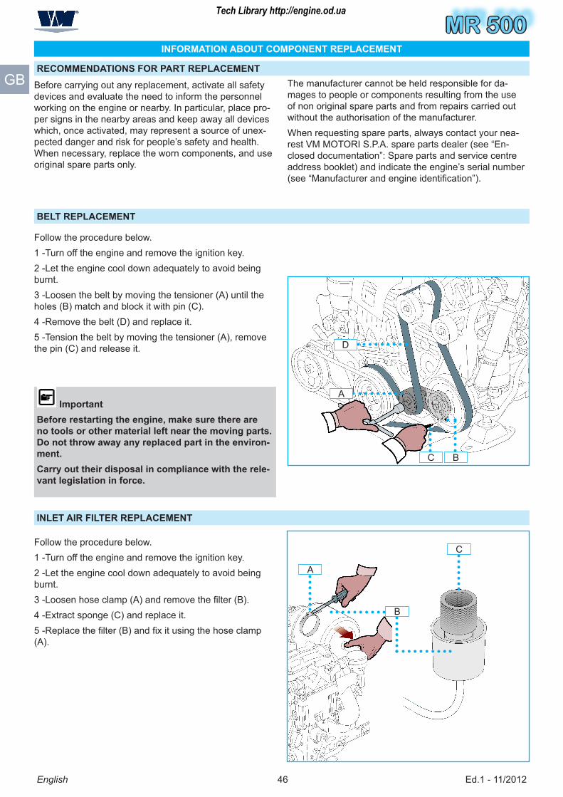
MR 500
Ed.1 - 11/2012�6
MR 500
D
C B
A
A
B
C
English
GB
INFORMATION ABOUT COMPONENT REPLACEMENT
RECOMMENDATIONS FOR PART REPLACEMENT
Before carrying out any replacement, activate all safety devices and evaluate the need to inform the personnel working on the engine or nearby. In particular, place pro-per signs in the nearby areas and keep away all devices which, once activated, may represent a source of unex-pected danger and risk for people’s safety and health. When necessary, replace the worn components, and use original spare parts only.
The manufacturer cannot be held responsible for da-mages to people or components resulting from the use of non original spare parts and from repairs carried out without the authorisation of the manufacturer.When requesting spare parts, always contact your nea-rest VM MOTORI S.P.A. spare parts dealer (see “En-closed documentation”: Spare parts and service centre address booklet) and indicate the engine’s serial number (see “Manufacturer and engine identification”).
BELT REPLACEMENT
Follow the procedure below.1 -Turn off the engine and remove the ignition key.2 -Let the engine cool down adequately to avoid being burnt.� -Loosen the belt by moving the tensioner (A) until the holes (B) match and block it with pin (C).� -Remove the belt (D) and replace it.� -Tension the belt by moving the tensioner (A), remove the pin (C) and release it.
ImportantBefore restarting the engine, make sure there are no tools or other material left near the moving parts. Do not throw away any replaced part in the environ-ment.Carry out their disposal in compliance with the rele-vant legislation in force.
INLET AIR FILTER REPLACEMENT
Follow the procedure below.1 -Turn off the engine and remove the ignition key.2 -Let the engine cool down adequately to avoid being burnt.3 -Loosen hose clamp (A) and remove the filter (B).� -Extract sponge (C) and replace it.5 -Replace the filter (B) and fix it using the hose clamp (A).
Tech Library http://engine.od.ua

MR 500MR 500
Ed.1 - 11/2012�7
MR 500
A
English
GB
ELECTROLYTIC ZINC REPLACEMENT
Follow the procedure below.1 -Turn off the engine and remove the ignition key.2 -Let the engine cool down adequately to avoid being burnt.� -Unscrew the nut and replace the electrolytic zinc (A).
ENGINE DISPOSALThis operation should be carried out by experienced ope-rators, in compliance with the legislation in force concer-ning safety at the workplace.Do not throw away non bio-degradable products and non ferrous components (rubber, PVC, resins, etc.).While decommissioning the engine, divide all the com-ponents depending on their chemical composition and dispose of them accordingly.
Tech Library http://engine.od.ua

MR 500
Ed.1 - 11/2012��
MR 500
English
GB
ELECTRICAL SYSTEM
ENGINE ELECTRICAL DIAGRAM
Tech Library http://engine.od.ua
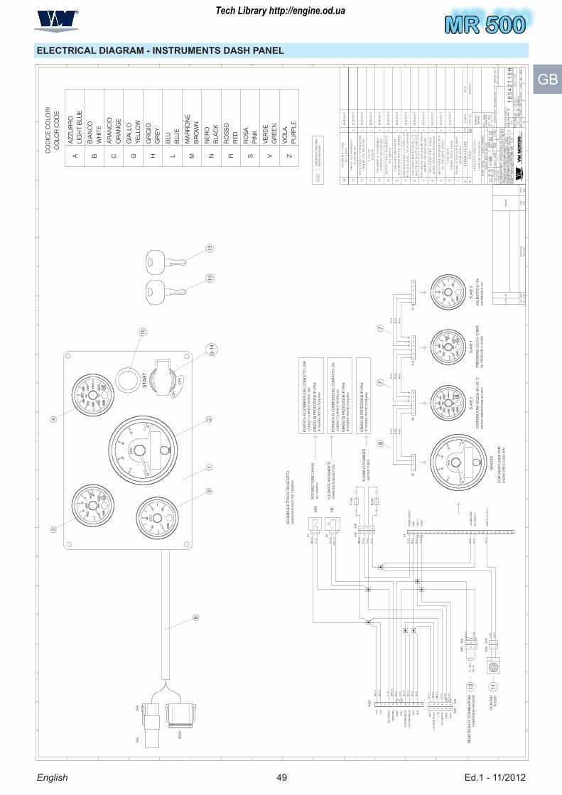
MR 500MR 500
Ed.1 - 11/2012�9
MR 500
English
GB
ELECTRICAL DIAGRAM - INSTRUMENTS DASH PANEL
Tech Library http://engine.od.ua