engineering expo presentation
TRANSCRIPT
Engineering Expo PresentationMultiphysics Modeling of a Pebble Bed Reactor
Mentored by Dr. Anthony Alberti
Group Members: Michael Branco-Katcher
Cole Evered Keenan Hoffman Zachary Ketrow
Gavin VandenBroeder
1
Presentation Outline1: Background (Slides 3-7)
• Advanced Reactors• TRISO Fuel• Pebble Bed Reactors
2
3: Design Challenges (Slides 20-23)• Processing DEM Data• Making Assumptions• Running the Simulation
2: Significance (Slides 8-19)• Homogenized Diffusion• Pebble Tracking Transport
(PTT)• Packing Fraction

Background
3
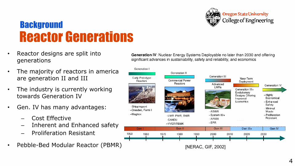
Reactor Generations• Reactor designs are split into
generations
• The majority of reactors in america are generation II and III
• The industry is currently working towards Generation IV
• Gen. IV has many advantages:
– Cost Effective– Inherent and Enhanced safety– Proliferation Resistant
• Pebble-Bed Modular Reactor (PBMR)
4
Background
[NERAC, GIF, 2002]
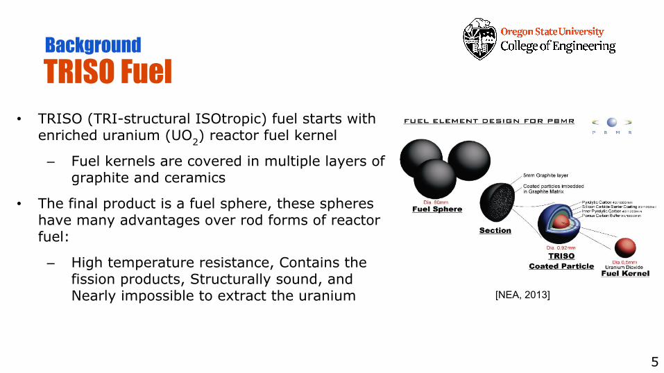
TRISO Fuel • TRISO (TRI-structural ISOtropic) fuel starts with
enriched uranium (UO2) reactor fuel kernel
– Fuel kernels are covered in multiple layers of graphite and ceramics
• The final product is a fuel sphere, these spheres have many advantages over rod forms of reactor fuel:
– High temperature resistance, Contains the fission products, Structurally sound, and Nearly impossible to extract the uranium
5
[NEA, 2013]
Background
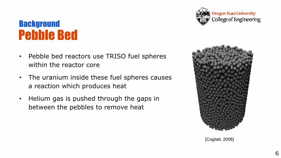
Pebble Bed• Pebble bed reactors use TRISO fuel spheres
within the reactor core
• The uranium inside these fuel spheres causes a reaction which produces heat
• Helium gas is pushed through the gaps in between the pebbles to remove heat
6
Background
[Cogliati, 2006]
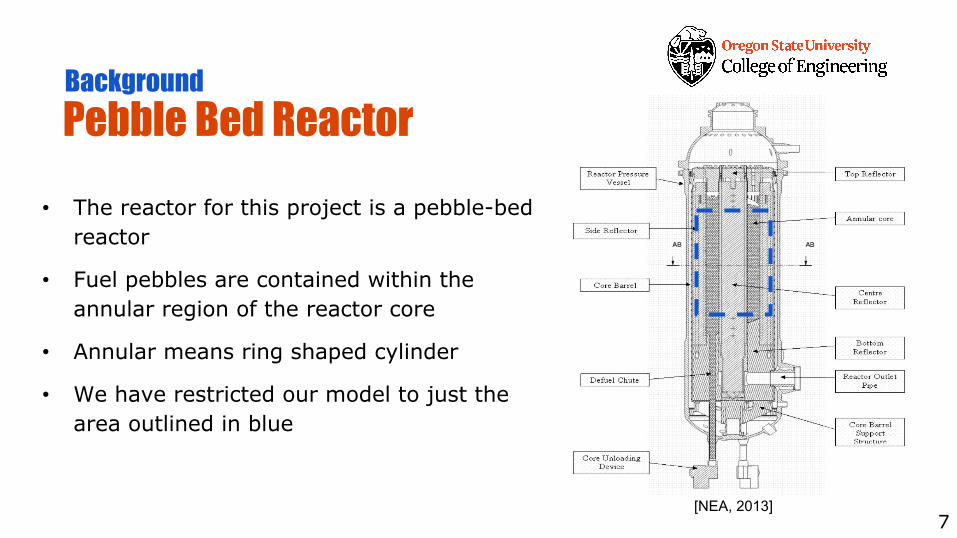
Pebble Bed Reactor• The reactor for this project is a pebble-bed
reactor
• Fuel pebbles are contained within the annular region of the reactor core
• Annular means ring shaped cylinder
• We have restricted our model to just the area outlined in blue
7
Background
[NEA, 2013]

Significance
8
Comparison Between Two Methods• This project compares two reactor core modeling methods
• The assumptions made in each model affect the neutron physics (neutronics)
• The first model is of a homogeneous core
– Physically unrealistic but proven and provides acceptable results
• The second is a core using a Pebble-Tracking Transport (PTT) algorithm
– Physically realistic but unproven and computationally expensive
9
Significance
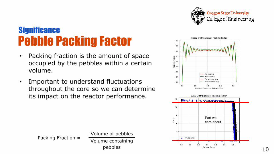
Pebble Packing Factor • Packing fraction is the amount of space
occupied by the pebbles within a certain volume.
• Important to understand fluctuations throughout the core so we can determine its impact on the reactor performance.
10
Significance
Part we care about
Packing Fraction = Volume of pebblesVolume containing
pebbles
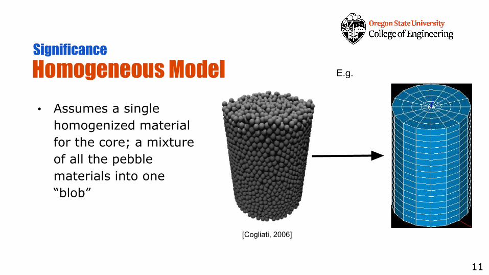
Homogeneous Model• Assumes a single
homogenized material for the core; a mixture of all the pebble materials into one “blob”
11
Significance
[Cogliati, 2006]
E.g.
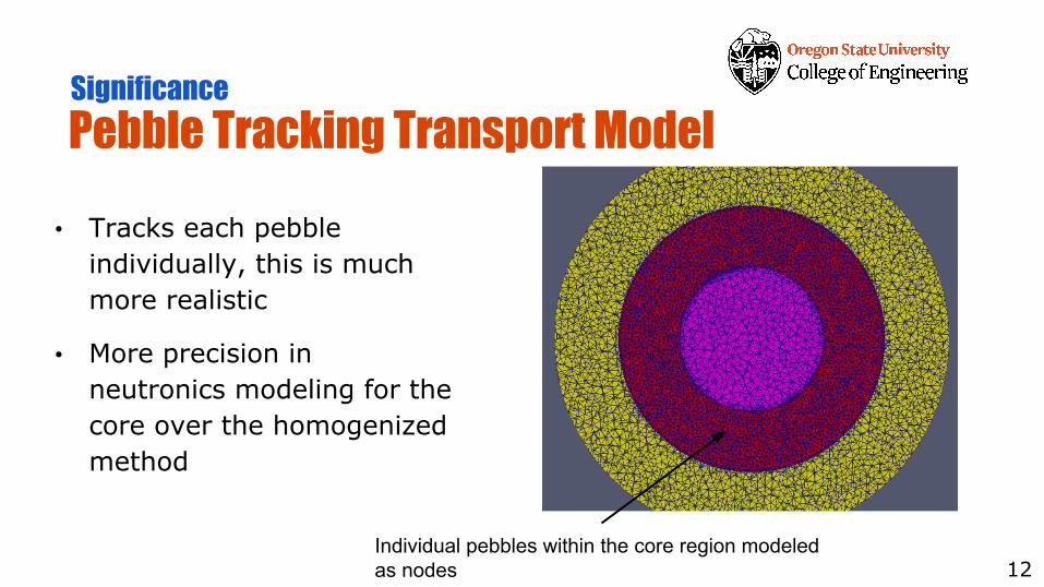
Pebble Tracking Transport Model• Tracks each pebble
individually, this is much more realistic
• More precision in neutronics modeling for the core over the homogenized method
12
Significance
Individual pebbles within the core region modeled as nodes
Accident Scenarios to Compare Methods• Two accident scenarios will be used in the comparison between
modeling methods
• Accident scenarios for this project:
– Before and after a seismic event (earthquake)
– Depressurized Loss of Forced Coolant (DLOFC)
• These scenarios represent design-basis accidents individually and beyond design-basis accidents when coupled
– Important for risk assessment and safety analysis for regulators like the Nuclear Regulatory Commision (NRC)
13
Significance
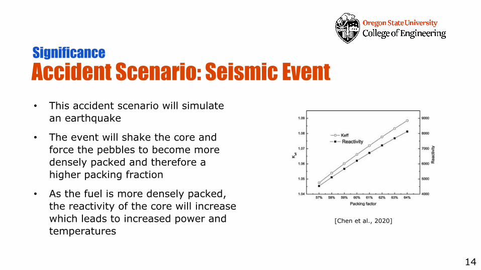
Accident Scenario: Seismic Event• This accident scenario will simulate
an earthquake
• The event will shake the core and force the pebbles to become more densely packed and therefore a higher packing fraction
• As the fuel is more densely packed, the reactivity of the core will increase which leads to increased power and temperatures
14
Significance
[Chen et al., 2020]
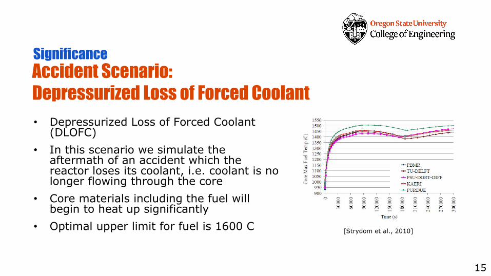
Accident Scenario: Depressurized Loss of Forced Coolant • Depressurized Loss of Forced Coolant
(DLOFC) • In this scenario we simulate the
aftermath of an accident which the reactor loses its coolant, i.e. coolant is no longer flowing through the core
• Core materials including the fuel will begin to heat up significantly
• Optimal upper limit for fuel is 1600 C
15
Significance
[Strydom et al., 2010]
MAMMOTH• For regulators it is important to have a comprehensive code that can
represent both normal operation and an accident scenario, and MAMMOTH is promising.
• MOOSE is the INL Multi-Physics Framework that allows for the construction and solving of Partial Differential Equations (PDEs) that represent physical system behavior.
• MAMMOTH is a MOOSE Module specifically designed for simulating Reactors.• Capable of simulating both a reactor in steady state and with transients
(constant conditions vs. changing).• A goal of this project is to evaluate the performance of MAMMOTH for PBRs.• MAMMOTH takes an input file that includes the mesh of our core and a set
of properties which we define to the core regions.16
Significance
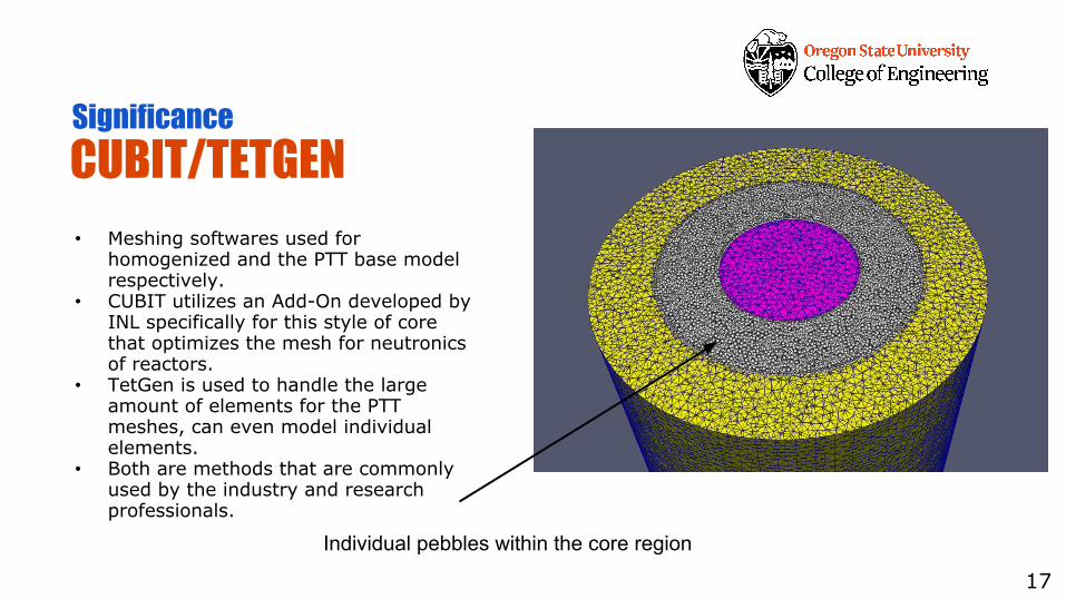
CUBIT/TETGEN• Meshing softwares used for
homogenized and the PTT base model respectively.
• CUBIT utilizes an Add-On developed by INL specifically for this style of core that optimizes the mesh for neutronics of reactors.
• TetGen is used to handle the large amount of elements for the PTT meshes, can even model individual elements.
• Both are methods that are commonly used by the industry and research professionals.
17
Significance
Individual pebbles within the core region
PEBBLES• Developed by Dr. Cogliati at INL, DEM code specifically for modeling
pebble distribution.• All fuel spheres are treated as individual elements, with their own center
location and a set physical properties.• At a starting point the real life forces acting on a pebble are converted to
equations the code can interpret.• At subsequent time steps, resultant equations from the system and
collisions of elements.
18
Significance
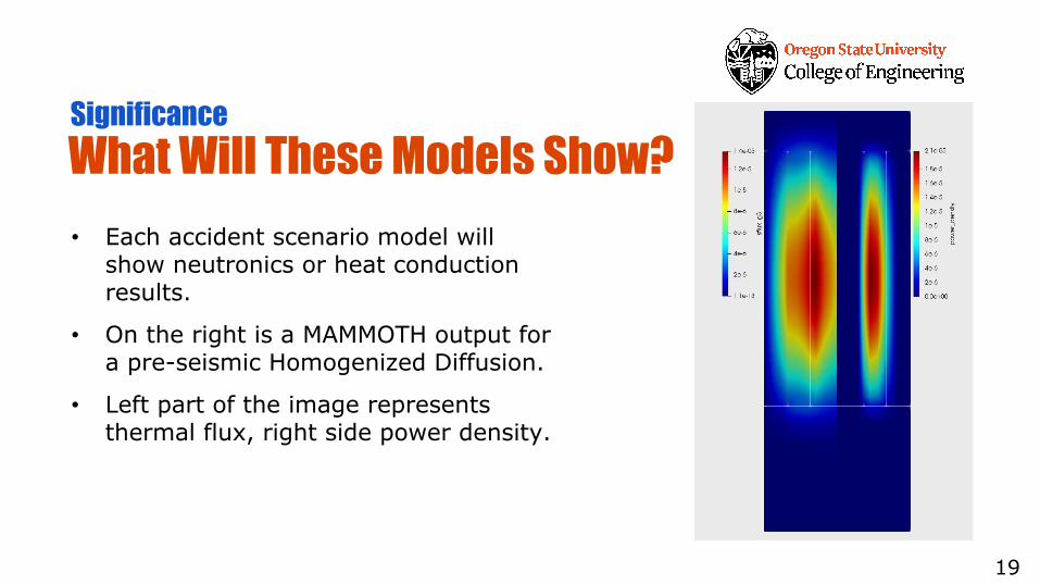
What Will These Models Show? • Each accident scenario model will
show neutronics or heat conduction results.
• On the right is a MAMMOTH output for a pre-seismic Homogenized Diffusion.
• Left part of the image represents thermal flux, right side power density.
19
Significance

Design Challenges
20
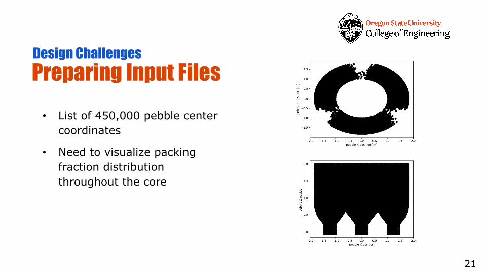
Preparing Input Files• List of 450,000 pebble center
coordinates
• Need to visualize packing fraction distribution throughout the core
21
Design Challenges
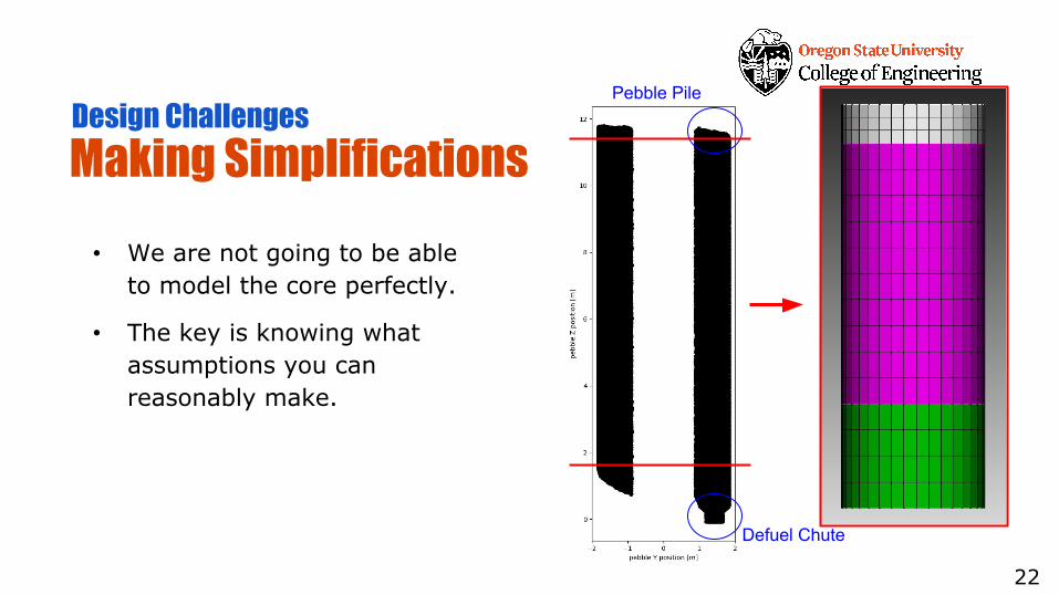
Making Simplifications• We are not going to be able
to model the core perfectly.
• The key is knowing what assumptions you can reasonably make.
22
Design Challenges
Defuel Chute
Pebble Pile
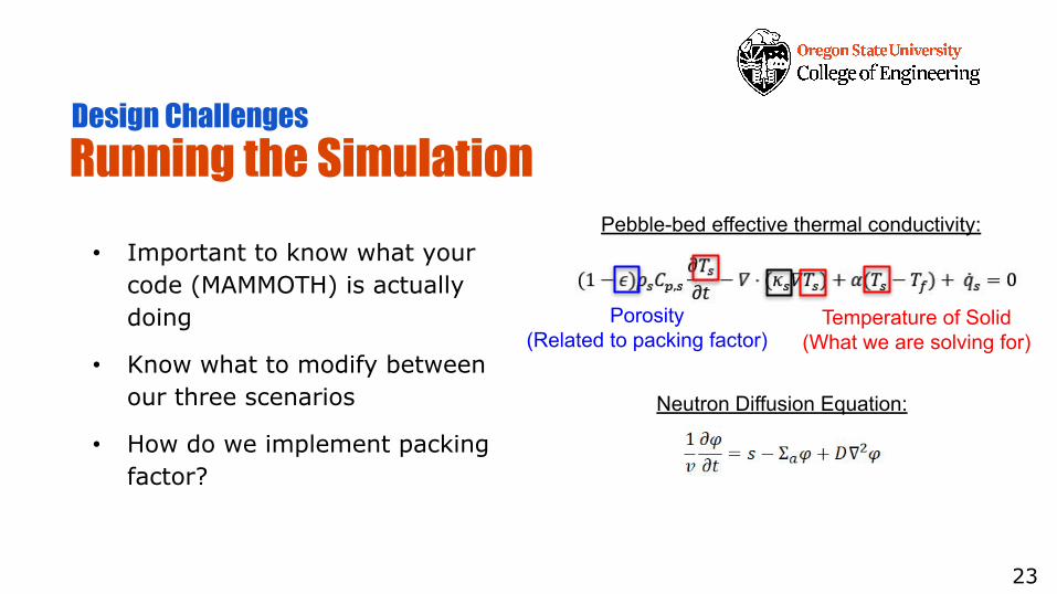
Running the Simulation • Important to know what your
code (MAMMOTH) is actually doing
• Know what to modify between our three scenarios
• How do we implement packing factor?
23
Design Challenges
Temperature of Solid(What we are solving for)
Porosity(Related to packing factor)
Pebble-bed effective thermal conductivity:
Neutron Diffusion Equation:

Questions?
24
References 1/21. Chen, X., Dai, Y., Yan, R., Mei, M., Zhang, J., Zou, Y., & Cai, X. (2020). Experimental study on the vibration behavior of
the pebble bed in PB-FHR. Annals of Nuclear Energy, 139, 107193. https://doi.org/10.1016/j.anucene.2019.1071932. Cogliati, J.,Ougouag, Abderrafi M. (2006). PEBBLES: A computer code for modeling Packing, Flow, and recirculation of
pebbles in a pebble bed reactor. U.S. DOE Idaho National Laboratory.3. Cisneros, Tomas A., (2013). Pebble bed reactors design optimization methods and their application to the pebble bed
fluoride Salt cooled reactor. University of California, Berkeley. 4. Cundall, P. A., & Strack, O. D. L. (1979). A discrete numerical model for granular assemblies. Geotechnique, 29(1),
47–65. https://doi.org/10.1680/geot.1979.29.1.475. Durst, P. C., Beddingfield, D., Boyer, B., Bean, R., Collins, M., Ehinger, M., Hanks, D., Moses, D. L., & Refalo, L. (2009).
Nuclear Safeguards Considerations for the Pebble Bed Modular Reactor (PBMR). U.S. DOE Idaho National Laboratory, Report # INL/EXT-09-16782. https://inldigitallibrary.inl.gov/sites/sti/sti/4374060.pdf
6. International Atomic Energy Agency (IAEA). (2011). Status report 70-Pebble Bed Modular Reactor (PBMR). International Atomic Energy Agency. https://aris.iaea.org/PDF/PBMR.pdf
7. Kaszynski, A. (2020). tetgen 0.5.1. PyPi. https://pypi.org/project/tetgen/#description8. Kruggel-Emden, H., Rickelt, S., Wirtz, S., & Scherer, V. (2008). A study on the validity of the multi-sphere Discrete
Element Method. Powder Technology, 188(2), 153–165. https://doi.org/10.1016/j.powtec.2008.04.0379. Mulder, E. J., & Boyes, W. A. (2020). Neutronics characteristics of a 165 MWth Xe-100 reactor. Nuclear Engineering and
Design, 357, 110415. https://doi.org/10.1016/j.nucengdes.2019.11041510. Nuclear Energy Agency (NEA). (2013). PBMR Coupled Neutronics/Thermal-Hydraulics Transient Benchmark: The
PBMR-400 Core Design. Nuclear Energy Agency NEA/NSC/DOC(2013)10. https://www.oecd-nea.org/jcms/pl_19318/pbmr-coupled-neutronics/thermal-hydraulics-transient-benchmark-the-pbmr-400-core-design-volume-1-the-benchmark-definition
25
References 2/211. Nuclear Energy Research Advisory Committee (NERAC), Generation IV International Forum (GIF). (2002). A Technology
Roadmap for Generation IV Nuclear Energy Systems. U.S. DOE Nuclear Energy Research Advisory Committee and the Generation IV International Forum. https://www.gen-4.org/gif/upload/docs/application/pdf/2013-09/genivroadmap2002.pdf
12. Ougouag, A. M., Ortensi, J., & Hiruta, H. (2009). Analysis of an Earthquake-Initiated-Transient in a PBR 2009 International Conference on Advances in Mathematics, Computational Methods, and Reactor Physics ANALYSIS OF AN EARTHQUAKE-INITIATED-TRANSIENT IN A PBR. American Nuclear Society.
14. Strydom, G., Reitsma, F., Ivanov, K., Ngeleka, P. T., & Ivanov, K. N. (2010). THE OECD/NEA/NSC PBMR 400 MW COUPLED NEUTRONICS THERMAL HYDRAULICS TRANSIENT BENCHMARK: TRANSIENT RESULTS. PHYSOR 2010 – Advances in Reactor Physics to Power the Nuclear Renaissance. https://doi.org/10.13140/2.1.4626.8164
14. Strydom, G. (2008). TINTE transient results for the OECD 400 MW PBMR benchmark. ICAPP 2008 Paper 8180. https://www.researchgate.net/publication/266672982
15. Strydom, G. (2004). TINTE Uncertainty Analysis of the Maximum Fuel Temperature During a DLOFC Event for the 400 MW Pebble Bed Modular Reactor. ICAPP 2004 Paper 4165. https://www.researchgate.net/publication/236370888
16. Suikkanen, H., Ritvanen, J., Jalali, P., & Kyrki-Rajamäki, R. (2014). Discrete element modelling of pebble packing in pebble bed reactors. Nuclear Engineering and Design, 273, 24–32. https://doi.org/10.1016/j.nucengdes.2014.02.022
17. Venter, P. J., Mitchell, M. N., & Fortier, F. (2005). PBMR REACTOR DESIGN AND DEVELOPMENT. 18th International Conference on Structural Mechanics in Reactor Technology. https://repository.lib.ncsu.edu/bitstream/handle/1840.20/31858/S02_2.pdf?sequence=1
18. Wang, Y., Ortensi, J., Schunert, S., & Laboure, V. (2018). A Pebble Tracking Transport Algorithm for Pebble Bed Reactor Analysis. PHYSOR 2018: Reactor Physics Paving The Way Towards More Efficient Systems, April, 1110–1124.
19. Yang, X., Gui, N., Tu, J., & Jiang, S. (2014). 3D DEM simulation and analysis of void fraction distribution in a pebble bed high temperature reactor. Nuclear Engineering and Design, 270, 404–411. https://doi.org/10.1016/j.nucengdes.2014.02.010 26