es600.2 synchronization and power management module user’s ... · es600.2 - user's guide 7...
TRANSCRIPT

ES600.2Synchronization and Power Management ModuleUser’s Guide

2
Copyright
The data in this document may not be altered or amended without special noti-fication from ETAS GmbH. ETAS GmbH undertakes no further obligation in rela-tion to this document. The software described in it can only be used if thecustomer is in possession of a general license agreement or single license. Usingand copying is only allowed in concurrence with the specifications stipulated inthe contract.
Under no circumstances may any part of this document be copied, reproduced,transmitted, stored in a retrieval system or translated into another languagewithout the express written permission of ETAS GmbH.
© Copyright 2016 ETAS GmbH, Stuttgart
The names and designations used in this document are trademarks or brandsbelonging to the respective owners.
ES600.2 - User's Guide R03 EN - 05.2016

Contents
ETAS Contents
1 About this Manual . . . . . . . . . . . . . . . . . . . . . . . . . . . . . . . . . . . . . . . . . . . . . . . . . 71.1 Identification of Safety Notices . . . . . . . . . . . . . . . . . . . . . . . . . . . . . . . . . . . 71.2 Presentation of Information . . . . . . . . . . . . . . . . . . . . . . . . . . . . . . . . . . . . . 71.3 Scope of Supply . . . . . . . . . . . . . . . . . . . . . . . . . . . . . . . . . . . . . . . . . . . . . . 81.4 Additional Information . . . . . . . . . . . . . . . . . . . . . . . . . . . . . . . . . . . . . . . . . 8
2 Basic Safety Notices . . . . . . . . . . . . . . . . . . . . . . . . . . . . . . . . . . . . . . . . . . . . . . . . 92.1 General Safety Information . . . . . . . . . . . . . . . . . . . . . . . . . . . . . . . . . . . . . . 92.2 Requirements for Users and Duties for Operators . . . . . . . . . . . . . . . . . . . . . 92.3 Intended Use . . . . . . . . . . . . . . . . . . . . . . . . . . . . . . . . . . . . . . . . . . . . . . . . 9
3 Hardware Description . . . . . . . . . . . . . . . . . . . . . . . . . . . . . . . . . . . . . . . . . . . . . . 133.1 Overview . . . . . . . . . . . . . . . . . . . . . . . . . . . . . . . . . . . . . . . . . . . . . . . . . . 13
3.1.1 Properties . . . . . . . . . . . . . . . . . . . . . . . . . . . . . . . . . . . . . . . . . . . 143.2 Housing . . . . . . . . . . . . . . . . . . . . . . . . . . . . . . . . . . . . . . . . . . . . . . . . . . . 143.3 Connections . . . . . . . . . . . . . . . . . . . . . . . . . . . . . . . . . . . . . . . . . . . . . . . . 15
3.3.1 Front side . . . . . . . . . . . . . . . . . . . . . . . . . . . . . . . . . . . . . . . . . . . 153.3.2 Rear side . . . . . . . . . . . . . . . . . . . . . . . . . . . . . . . . . . . . . . . . . . . . 15
3.4 Indicators . . . . . . . . . . . . . . . . . . . . . . . . . . . . . . . . . . . . . . . . . . . . . . . . . . 16
4 Functional Description. . . . . . . . . . . . . . . . . . . . . . . . . . . . . . . . . . . . . . . . . . . . . . 194.1 Block diagram . . . . . . . . . . . . . . . . . . . . . . . . . . . . . . . . . . . . . . . . . . . . . . . 194.2 Power supply . . . . . . . . . . . . . . . . . . . . . . . . . . . . . . . . . . . . . . . . . . . . . . . 194.3 Ethernet switch . . . . . . . . . . . . . . . . . . . . . . . . . . . . . . . . . . . . . . . . . . . . . . 20
4.3.1 "FE-HOST" host connection . . . . . . . . . . . . . . . . . . . . . . . . . . . . . 204.3.2 "GE-HOST" host connection . . . . . . . . . . . . . . . . . . . . . . . . . . . . . 204.3.3 Ethernet connections "ETH1" to "ETH6". . . . . . . . . . . . . . . . . . . . 20
4.4 Time synchronization . . . . . . . . . . . . . . . . . . . . . . . . . . . . . . . . . . . . . . . . . 214.5 "Wake-Up" function . . . . . . . . . . . . . . . . . . . . . . . . . . . . . . . . . . . . . . . . . 214.6 Firmware update . . . . . . . . . . . . . . . . . . . . . . . . . . . . . . . . . . . . . . . . . . . . 22
ES600.2 - User's Guide 3

4
Contents ETAS
5 Commissioning . . . . . . . . . . . . . . . . . . . . . . . . . . . . . . . . . . . . . . . . . . . . . . . . . . . 235.1 Assembly and Interlocking . . . . . . . . . . . . . . . . . . . . . . . . . . . . . . . . . . . . . 23
5.1.1 General installation recommendations . . . . . . . . . . . . . . . . . . . . . 235.1.2 Fastening the module on a carrier system . . . . . . . . . . . . . . . . . . . 235.1.3 Mechanically connecting several modules . . . . . . . . . . . . . . . . . . . 24
5.2 Applications . . . . . . . . . . . . . . . . . . . . . . . . . . . . . . . . . . . . . . . . . . . . . . . . 265.3 Cabling . . . . . . . . . . . . . . . . . . . . . . . . . . . . . . . . . . . . . . . . . . . . . . . . . . . . 27
5.3.1 Putting a simple module compound in operation. . . . . . . . . . . . . . 275.3.2 Putting a complex module compound in operation . . . . . . . . . . . . 28
6 Technical Data . . . . . . . . . . . . . . . . . . . . . . . . . . . . . . . . . . . . . . . . . . . . . . . . . . . 316.1 General data . . . . . . . . . . . . . . . . . . . . . . . . . . . . . . . . . . . . . . . . . . . . . . . . 31
6.1.1 Identifications on the product . . . . . . . . . . . . . . . . . . . . . . . . . . . . 316.1.2 Standards met . . . . . . . . . . . . . . . . . . . . . . . . . . . . . . . . . . . . . . . . 326.1.3 Ambient conditions . . . . . . . . . . . . . . . . . . . . . . . . . . . . . . . . . . . 336.1.4 Maintenance of the product . . . . . . . . . . . . . . . . . . . . . . . . . . . . . 336.1.5 Cleaning the product. . . . . . . . . . . . . . . . . . . . . . . . . . . . . . . . . . . 336.1.6 Mechanical data . . . . . . . . . . . . . . . . . . . . . . . . . . . . . . . . . . . . . . 33
6.2 RoHS conformity . . . . . . . . . . . . . . . . . . . . . . . . . . . . . . . . . . . . . . . . . . . . . 336.2.1 European Union . . . . . . . . . . . . . . . . . . . . . . . . . . . . . . . . . . . . . . 336.2.2 China . . . . . . . . . . . . . . . . . . . . . . . . . . . . . . . . . . . . . . . . . . . . . . 34
6.3 CE marking . . . . . . . . . . . . . . . . . . . . . . . . . . . . . . . . . . . . . . . . . . . . . . . . . 346.4 Product return and recycling . . . . . . . . . . . . . . . . . . . . . . . . . . . . . . . . . . . . 346.5 Use of Open Source software . . . . . . . . . . . . . . . . . . . . . . . . . . . . . . . . . . . 346.6 System requirements . . . . . . . . . . . . . . . . . . . . . . . . . . . . . . . . . . . . . . . . . 35
6.6.1 Hardware . . . . . . . . . . . . . . . . . . . . . . . . . . . . . . . . . . . . . . . . . . . 356.6.2 Supported applications and software prerequisites . . . . . . . . . . . . 35
6.7 Electrical data . . . . . . . . . . . . . . . . . . . . . . . . . . . . . . . . . . . . . . . . . . . . . . . 366.7.1 Voltage supply . . . . . . . . . . . . . . . . . . . . . . . . . . . . . . . . . . . . . . . 366.7.2 "GE-HOST" connection . . . . . . . . . . . . . . . . . . . . . . . . . . . . . . . . 376.7.3 "FE-HOST" connection . . . . . . . . . . . . . . . . . . . . . . . . . . . . . . . . 376.7.4 Ethernet connections "ETH1" to "ETH6" . . . . . . . . . . . . . . . . . . . 38
6.8 Terminal assignment . . . . . . . . . . . . . . . . . . . . . . . . . . . . . . . . . . . . . . . . . 396.8.1 Connection "7-29 V" . . . . . . . . . . . . . . . . . . . . . . . . . . . . . . . . . . 396.8.2 "FE-HOST" connection . . . . . . . . . . . . . . . . . . . . . . . . . . . . . . . . . 396.8.3 "GE-HOST" connection . . . . . . . . . . . . . . . . . . . . . . . . . . . . . . . . 406.8.4 Connections "ETH1" to "ETH6" . . . . . . . . . . . . . . . . . . . . . . . . . . 40
7 Cables and Accessories . . . . . . . . . . . . . . . . . . . . . . . . . . . . . . . . . . . . . . . . . . . . . 417.1 Cable for the "7-29 V DC" connection . . . . . . . . . . . . . . . . . . . . . . . . . . . . 41
7.1.1 CBP120 Cable . . . . . . . . . . . . . . . . . . . . . . . . . . . . . . . . . . . . . . . . 427.1.2 CBP1205 Cable . . . . . . . . . . . . . . . . . . . . . . . . . . . . . . . . . . . . . . . 43
7.2 Cable for the "FE-HOST" connection . . . . . . . . . . . . . . . . . . . . . . . . . . . . . 447.3 Cable for the "GE-HOST" connection . . . . . . . . . . . . . . . . . . . . . . . . . . . . . 447.4 Cable for the connections "ETH1" to "ETH6" . . . . . . . . . . . . . . . . . . . . . . . 45
7.4.1 Cable CBE130-x . . . . . . . . . . . . . . . . . . . . . . . . . . . . . . . . . . . . . . 457.4.2 Cable CBE140 . . . . . . . . . . . . . . . . . . . . . . . . . . . . . . . . . . . . . . . . 457.4.3 Adapter cable . . . . . . . . . . . . . . . . . . . . . . . . . . . . . . . . . . . . . . . . 46
ES600.2 - User's Guide

ETAS Contents
8 Order Information. . . . . . . . . . . . . . . . . . . . . . . . . . . . . . . . . . . . . . . . . . . . . . . . . 478.1 ES600.2 . . . . . . . . . . . . . . . . . . . . . . . . . . . . . . . . . . . . . . . . . . . . . . . . . . . 47
8.1.1 ES600.2 with CBP120 Power Supply Cable . . . . . . . . . . . . . . . . . . 478.1.2 ES600.2 with CBP1205 Power Supply Cable . . . . . . . . . . . . . . . . . 47
8.2 Accessories . . . . . . . . . . . . . . . . . . . . . . . . . . . . . . . . . . . . . . . . . . . . . . . . . 488.2.1 Cable . . . . . . . . . . . . . . . . . . . . . . . . . . . . . . . . . . . . . . . . . . . . . . 488.2.2 Housing accessories. . . . . . . . . . . . . . . . . . . . . . . . . . . . . . . . . . . . 49
9 ETAS Contact Addresses . . . . . . . . . . . . . . . . . . . . . . . . . . . . . . . . . . . . . . . . . . . . 50
Figures . . . . . . . . . . . . . . . . . . . . . . . . . . . . . . . . . . . . . . . . . . . . . . . . . . . . . . . . . 51
Index . . . . . . . . . . . . . . . . . . . . . . . . . . . . . . . . . . . . . . . . . . . . . . . . . . . . . . . . . . 53
ES600.2 - User's Guide 5

6
Contents ETAS
ES600.2 - User's Guide

ETAS About this Manual
1 About this Manual
This chapter contains information about the following topics:
• "Identification of Safety Notices" on page 7,
• "Presentation of Information" on page 7,
• "Scope of Supply" on page 8,
• "Additional Information" on page 8.
1.1 Identification of Safety Notices
The safety notices contained in this manual are identified with the danger symbolshown below:
The safety notices shown below are used for this purpose. They provide notes toextremely important information. Please read this information carefully.
1.2 Presentation of Information
All activities to be performed by the user are presented in a "Use Case" format.That is, the goal to be accomplished is briefly defined in the heading, and therespective steps required for reaching this goal are then presented in a list. Thepresentation looks as follows:
Goal definition:
any advance information...
• Step 1
Any explanation for step 1...
• Step 2
Any explanation for step 2...
• Step 3
Any explanation for step 3...
DANGER!
indicates an immediate danger with a high risk of death or serious injury, if not avoided.
WARNING!
indicates a possible danger with moderate risk of death or (serious) injury, if not avoided.
CAUTION!
identifies a hazard with low risk that could result in minor or medium physical injuries or property damages if not avoided.
ES600.2 - User's Guide 7

8
About this Manual ETAS
Any concluding comments...
Typographical conventions
The following typographical conventions are used:
Important notes for the user are presented as follows:
1.3 Scope of Supply
Prior to the initial commissioning of the module, please check whether the mod-ule was delivered with all required components and cables (see chapter 8.1on page 47).
Additional cables and adapters can be obtained separately from ETAS. A list ofavailable accessories and their order designation is located in chapter "Accesso-ries" on page 48 of this manual or in the ETAS product catalog.
1.4 Additional Information
The configuration instructions for the module under INCA can be found in thecorresponding software documentation.
Bold Labels of the device
Italic Particularly important text passages
Note
Important note for the user.
ES600.2 - User's Guide

ETAS Basic Safety Notices
2 Basic Safety Notices
This chapter contains information about the following topics:
• "General Safety Information" on page 9,
• "Requirements for Users and Duties for Operators" on page 9,
• "Intended Use" on page 9.
2.1 General Safety Information
Please observe the Product Safety Notices ("ETAS Safety Notice") and the follow-ing safety notices to avoid health issues or damage to the device.
ETAS GmbH does not assume any liability for damages resulting from improperhandling, unintended use or non-observance of the safety precautions.
2.2 Requirements for Users and Duties for Operators
The product may be assembled, operated and maintained only if you have thenecessary qualification and experience for this product. Improper use or use by auser without sufficient qualification can lead to damages or injuries to one'shealth or damages to property.
General safety at work
The existing regulations for safety at work and accident prevention must be fol-lowed. All applicable regulations and statutes regarding operation must bestrictly followed when using this product.
2.3 Intended Use
Application area of the product
This product was developed and approved for applications in the automotivesector. The module is suitable for use in interiors, in the passenger cell or in thetrunk of vehicles. The module is not suitable for installation in the engine com-partment and similar environments. For use in other application areas, pleasecontact your ETAS contact partner.
Requirements for the technical state of the product
The product is designed in accordance with state-of-the-art technology and rec-ognized safety rules. The product may be operated only in a technically flawlesscondition and according to the intended purpose and with regard to safety anddangers as stated in the respective product documentation. If the product is notused according to its intended purpose, the protection of the product may beimpaired.
Note
Carefully read the documentation (Product Safety Advice and this User's Guide) that belongs to the product prior to the startup.
ES600.2 - User's Guide 9

10
Basic Safety Notices ETAS
Requirements for operation
• Use the product only according to the specifications in the corresponding User's Guide. With any deviating operation, the product safety is no lon-ger ensured.
• Observe the requirements on the ambient conditions.
• Do not use the product in a wet or damp environment.
• Do not use the product in potentially explosive atmospheres.
Electrical safety and power supply
• Observe the regulations applicable at the operating location concerning electrical safety as well as the laws and regulations concerning work safety!
• Connect only current circuits with safety extra-low voltage in accordance with EN 61140 (degree of protection III) to the connections of the module.
• Ensure that the connection and setting values are being followed (see the information in the chapter "Technical data").
• Do not apply any voltages to the connections of the module that do not correspond to the specifications of the respective connection.
Power supply
• The power supply for the product must be safely disconnected from the supply voltage. For example, use a car battery or a suitable lab power sup-ply.
• Use only lab power supplies with double protection to the supply network (with double insulation/reinforced insulation (DI/ RI)).
• The lab power supply must be approved for an operating altitude of 5000 m and for an ambient temperature of up to 70 °C.
• In regular operation of the modules as well as very long standby opera-tion, a discharge of the vehicle battery is possible.
Connection to the power supply
• The power cable must not be connected directly to the vehicle battery or lab power supply, but via a fuse of up to 20 A.
• Ensure that the connections of the lab power supply, the power supply at the module and the vehicle battery are easily accessible!
• Route the power cord in such a way that it is protected against abrasion, damages, deformation and kinking. Do not place any objects on the power cord!
DANGER!
Dangerous electrical voltage!Connect the power cable only with a suitable vehicle battery or with a suitable lab power supply! The connection to power outlets is not allowed!To prevent an inadvertent insertion in power outlets, ETAS recom-mends to equip the power cables with safety banana plugs in areas with power outlets.
ES600.2 - User's Guide

ETAS Basic Safety Notices
Disconnecting from the power supply
The module does not have an operating voltage switch. The module can be de-energized as follows:
• Disconnecting the module from the lab power supply
– Separating device is the lab plug of the power cord or
– Separating device is the plug of the power cord at the connection of the module
• Disconnecting the module from the vehicle battery
– Separating device is the lab plug of the power cord or
– Separating device is the plug of the power cord at the connection of the module
• Disconnecting the vehicle battery.
Approved cables
• Use exclusively ETAS cables at the connections of the module!
• Adhere to the maximum permissible cable lengths!
• Do not use any damaged cables! Cables may be repaired only by ETAS!
• Never apply force to insert a plug into a socket. Ensure that there is no contamination in and on the connection, that the plug fits the socket, and that you correctly aligned the plugs with the connection.
Requirements for the location
• Position the module or the module stack on a smooth, level and solid underground.
• The module or the module stack must always be securely fastened.
Fixing the modules on a carrier system
• When selecting the carrier system, observe the static and dynamic forces that could be created by the module or the module stack on the carrier system.
Requirements on the ventilation
• Keep the module away from heat sources and protect it against direct exposure to the sun.
• The free space above and behind the module must be selected so that sufficient air circulation is ensured.
Assembling (interconnecting) the modules
• Prior to assembling (interconnecting) or separating a module stack, the modules must be disconnected from the supply voltage or they have to be in the standby operating mode.
Transport
• Stack and connect the modules only at the location of the startup!
• Do not transport the modules at the cable of the module or any other cables.
ES600.2 - User's Guide 11

12
Basic Safety Notices ETAS
Maintenance
The product is maintenance-free.
Repair
If an ETAS hardware product should require a repair, return the product to ETAS.
Cleaning the module housing
• Use a dry or lightly moistened, soft, lint-free cloth for cleaning the module housing.
• Do not user any sprays, solvents or abrasive cleaners which could damage the housing.
• Ensure that no moisture enters the housing. Never spray cleaning agents directly onto the module.
Ambient conditions
The housing and the connectors of the module as well as the plug connectors ofthe cables meet the degree of protection IP40.
Opening the module
Potential equalization
Cabling
For detailed information about cabling, see the User's Guide of the module.
CAUTION!
Damage to the module and loss of properties based on IP40!Do not open or change the module housing!Work on the module housing may only be performed by ETAS.
CAUTION!
Potential equalization in the vehicle is possible via the shield of the connecting cables of the modules!Install the modules only at locations with the same electrical potential or isolate the modules from the installation location.
ES600.2 - User's Guide

ETAS Hardware Description
3 Hardware Description
This chapter contains information about the following topics:
• "Overview" on page 13
• "Housing" on page 14
• "Connections" on page 15 and
• "Indicators" on page 16.
3.1 Overview
The ES600.2 Synchronization and Power Management Module is an Ethernetswitch with integrated voltage supply and time synchronization for connectingseveral data acquisition or interface modules to a host PC. The ES600.2 modulescan be cascaded so that you can also build larger module blocks.
Fig. 3-1 ES600.2 Synchronization and Power Management Module
The ES600.2 module is equipped with two upstream Ethernet connections (oneGigabit Ethernet and one Fast Ethernet connection) for the data exchange withthe host PC or a drive recorder.
The six downstream Ethernet connections of the module can be connected withnetwork, measuring, calibration and rapid prototyping modules. ECUs that areequipped with an XETK or feature a separate Ethernet interface, can be con-nected directly to these Ethernet connections.
The ES600.2 supplies connected measuring modules of the series ES4xx / ES6xxwith current and carries out the data exchange with the modules using a com-mon cable. The integrated power management function sequentially switches inthe connected modules This allows preventing high start-up peaks.
Note
The host PC can be connected either with the "GE-HOST" or "FE-HOST" con-nection.The drive recorder ES720.1 can be connected with the "FE-HOST" connection.
ES600.2 - User's Guide 13

14
Hardware Description ETAS
The ES600.2 module synchronizes all connected modules and their measuringchannels. Such a system offers a high time stability with the support of INCA. Aphase shift of the signals is ruled out and a time-synchronous scanning of themeasuring channels of the connected modules and module arrangements isensured.
The ES600.2 module and the corresponding cables are designed for use in thelab, at the test bench and in the passenger cell of motor vehicles.
3.1.1 Properties
The most important properties of the ES600.2 at a glance:
• Ethernet switch with 10/100/1000 Mbit/s data rate
• A host connection (upstream, Gigabit Ethernet)
• A host connection (upstream, Fast Ethernet)
• Six connections for compatible modules (downstream, Fast Ethernet)
• Status indicator for every connection
• Sequential switch-on of the connected modules to avoid high start-up peaks
• Automatic standby function for the connected modules
• Precise synchronization of all connected modules and their measuring channels
• Automotive-capable module that is suitable for use in the development environment and in the vehicle on test courses.
– Electrical isolation of the channels from each other, from device ground and from the supply voltage
– Immune to ambient conditions (temperature, EMC)
– Wide supply voltage range
– High level of mechanical stability and robustness
The complete technical data of the ES600.2 are located in the chapter "TechnicalData" on page 31.
3.2 Housing
For the ES600.2, a housing with connections on the device front side and thedevice rear side is used. The robust metal housing of the ES600.2 is fitted withnon-slip plastic feet.
It can easily be screwed onto a carrier system for fastening in a vehicle or lab. Thehousings of this device family can also be connected with each other quickly andeasily (see chapter 5.1 on page 23).
ES600.2 - User's Guide
ETAS Hardware Description
3.3 Connections
3.3.1 Front side
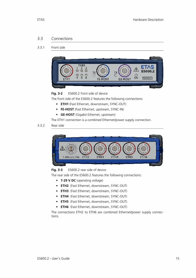
Fig. 3-2 ES600.2 front side of device
The front side of the ES600.2 features the following connections:
• ETH1 (Fast Ethernet, downstream, SYNC-OUT)
• FE-HOST (Fast Ethernet, upstream, SYNC-IN)
• GE-HOST (Gigabit Ethernet, upstream)
The ETH1 connection is a combined Ethernet/power supply connection.
3.3.2 Rear side
Fig. 3-3 ES600.2 rear side of device
The rear side of the ES600.2 features the following connections:
• 7-29 V DC (operating voltage)
• ETH2 (Fast Ethernet, downstream, SYNC-OUT)
• ETH3 (Fast Ethernet, downstream, SYNC-OUT)
• ETH4 (Fast Ethernet, downstream, SYNC-OUT)
• ETH5 (Fast Ethernet, downstream, SYNC-OUT)
• ETH6 (Fast Ethernet, downstream, SYNC-OUT)
The connections ETH2 to ETH6 are combined Ethernet/power supply connec-tions.
ES600.2 - User's Guide 15

16
Hardware Description ETAS
3.4 Indicators
The front side of the module features LEDs for indicating the operating, error andsynchronization state of the module (see Fig. 3-2 on page 15.
The FE-HOST connection is assigned a TX LED.
Note
The flashing of the LED is differentiated in slow (3 times per second), medium (6 times per second) and fast (12 times per second).
LED Indication Operating state
ON Off No power supply
Flashing green(0.1 s on,1.9 s off)
Module in operating mode "Standby", mini-mum current consumption. Changing to the "Normal" state requires a Wake-Up event (see chapter 4.5 on page 21).
Green Module in operating mode "Normal"
Green(briefly flashing brighter)
Module is synchronization master, module is not externally synchronized
Green(briefly flashing darker)
Module is synchronization slave, module is externally synchronized: at FE-HOST connec-tion
Flashing red Firmware update is being performed
Red Error
LED Indication Operating state
TX Off No Ethernet connection
Green Ethernet connection (upstream) active
Flashing green (slow)
Data transfer with 10 Mbit/s
Flashing green (medium)
Data transfer with 100 Mbit/s
t
t
ES600.2 - User's Guide

ETAS Hardware Description
The GE-HOST connection is assigned a TX LED.
The connections ETH1 to ETH6 are each assigned an LED(TX/ER1 to TX/ER6).
All LEDs light up briefly when switching on the ES600.2.
LED Indication Operating state
TX Off No Ethernet connection
Green Ethernet connection (upstream) active
Flashing green (slow)
Data transfer with 10 Mbit/s
Flashing green (medium)
Data transfer with 100 Mbit/s
Flashing green (fast)
Data transfer with 1000 Mbit/s
LED Indication Operating state
TX/ER Off No Ethernet connection
Green Ethernet connection (downstream) active
Flashing green (slow)
Data transfer with 10 Mbit/s
Flashing green (medium)
Data transfer with 100 Mbit/s
Red Current overload by the connected module
ES600.2 - User's Guide 17

18
Hardware Description ETAS
ES600.2 - User's Guide
ETAS Functional Description
4 Functional Description
This chapter contains information about the following topics:
• "Block diagram" on page 19
• "Power supply" on page 19
• "Ethernet switch" on page 20
• "Time synchronization" on page 21
• ""Wake-Up" function" on page 21 and
• "Firmware update" on page 22.
4.1 Block diagram
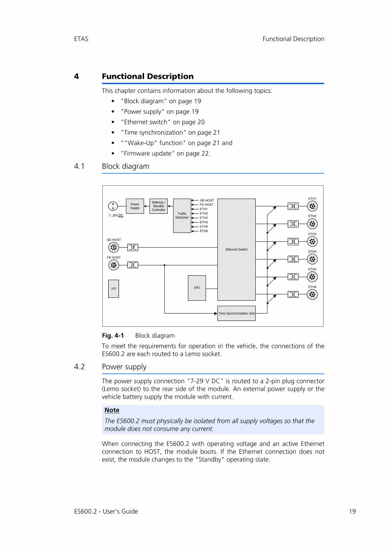
Fig. 4-1 Block diagram
To meet the requirements for operation in the vehicle, the connections of theES600.2 are each routed to a Lemo socket.
4.2 Power supply
The power supply connection "7-29 V DC" is routed to a 2-pin plug connector(Lemo socket) to the rear side of the module. An external power supply or thevehicle battery supply the module with current.
When connecting the ES600.2 with operating voltage and an active Ethernetconnection to HOST, the module boots. If the Ethernet connection does notexist, the module changes to the "Standby" operating state.
Note
The ES600.2 must physically be isolated from all supply voltages so that the module does not consume any current.
Time Synchronization Unit
7..29V DC
CPU
Ethernet Switch
Traffic Detection
GE-HOSTPower Supply
WakeUp / Standby
Controller
FE-HOST
ETH1
ETH2
ETH3
ETH4
ETH5
ETH6
ETH5
ETH6
FE-HOST
GE-HOST
LED
ETH4
ETH3
ETH2
ETH1
ES600.2 - User's Guide 19

20
Functional Description ETAS
4.3 Ethernet switch
The integrated Ethernet switch is used for connecting the ES600.2 module andadditional measuring or interface modules to a user PC. The data acquisition ofthe connected modules is done synchronized (ETAS device synchronization, seechapter 4.4 on page 21). The Ethernet switch can be cascaded with additionalnetwork modules so that you can also build larger blocks of measuring and inter-face modules.
The switch is equipped with a host connection (Fast Ethernet), a host connection(Gigabit Ethernet) and six Ethernet connections (10/100BaseT Ethernet).
All connections of the switch, except for the Ethernet connections "ETH1" to"ETH6", are electrically isolated from each other and from the power supply.
4.3.1 "FE-HOST" host connection
The upstream "FE-HOST" Ethernet interface connects the ES600.2 module withthe user PC or the downstream Ethernet interface of another module. This inter-face enables the ETAS software tools to access the connected modules.
"Wake-Up" function
The "FE-HOST" Ethernet interface supports the "Wake-Up" function (see chap-ter 4.5 on page 21).
Compatible modules
A list of the compatible modules is located in chapter 6.7.3 on page 37.
4.3.2 "GE-HOST" host connection
The upstream "GE-HOST" Ethernet interface connects the ES600.2 module withthe user PC or the downstream Ethernet interface of another module. This inter-face enables the ETAS software tools to access the connected modules.
"Wake-Up" function
The "GE-HOST" Ethernet interface supports the "Wake-Up" function (see chap-ter 4.5 on page 21).
Compatible modules
A list of the compatible modules is located in chapter 6.7.2 on page 37.
4.3.3 Ethernet connections "ETH1" to "ETH6"
The ES600.2 module provides six downstream Ethernet interfaces for additionalmodules. The Ethernet interfaces "ETH1" to "ETH6" based on the 10/100BaseTstandard can be operated either with 10 or 100 Mbit/s, half or full duplex. Theswitchover is done automatically to the highest possible connection speed.
ECUs that are equipped with an XETK or feature a separate Ethernet interface,can be connected directly to the module and communicate with the applicationsoftware via XCP-on-Ethernet.
ES600.2 - User's Guide

ETAS Functional Description
Module compound
The connections "ETH1" to "ETH6" connect the ES600.2 module with addi-tional ES600 modules, measuring, calibration and rapid prototyping modules.The cascadability also allows implementing larger blocks of measuring and inter-face modules.
Power supply of connected modules
The ES600.2 can also take on the power supply of connected ES4xx modules andES6xx modules via the Ethernet connecting cable. Observe the maximum outputcurrent at the Ethernet interfaces when cascading the modules.
Other modules connected via Ethernet cable must be cabled separately with thepower supply.
"Wake-Up" function
The Ethernet interfaces "ETH1" to "ETH6" support the "Wake-Up" function(see chapter 4.5 on page 21).
Compatible modules
A list of the compatible modules is located in chapter 6.7.4 on page 38.
4.4 Time synchronization
To synchronize the measuring channels in a module compound, the modules ofthe system provide a global time clock.
Modules connected to the "FE-HOST" interface can synchronize the ES600.2(SYNC-IN). If no synchronization signal is received at the "FE-HOST" connection,the ES600.2 automatically takes over the function of the master module for thesynchronization.
The time synchronization unit of the ES600.2 master synchronizes the connectedmodules via Ethernet lines. At the connections "ETH1" to "ETH6", the synchro-nization signal is passed on to connected modules (SYNC-OUT). The slave mod-ules adjust to the cycle specified by the master module.
A phase shift of the individual measuring signals to each other is ruled out, evenif the measured values are acquired from different modules.
The data of all connected modules of the series ES4xx, ES51x, ES6xx and theXETK are acquired synchronously (ETAS device synchronization).
4.5 "Wake-Up" function
If the system is used in a vehicle, the energy consumption must be as low aspossible since the measuring setup is supplied by a battery. For this reason, theES600.2 module is equipped with a link signal detector at all connections forautomatic power-save function.
With the "Wake-Up" function, the module can automatically switch betweenthe operating states "Standby" and "On".
The ES600.2 and modules connected to it automatically switch to the "Standby"operating state if no connection receives any link signals any longer or the hostcomputer is switched off or disconnected. As soon as at least one of these con-
ES600.2 - User's Guide 21

22
Functional Description ETAS
nections receives link signals or the host computer is activated again, the moduleautomatically changes to the "On" operating state ("Wake-Up" function) andautomatically switches on all ETAS modules connected in the measuring system.
4.6 Firmware update
The firmware of the ES600.2 can be updated by the user so that future versionsof the module can also be used. The firmware update is done with the help ofthe service software "Hardware Service Pack" (HSP) from the connected PC.
Note
The automatic switch-on of the ES600.2 via the "Wake-Up" function is possible at all Ethernet connections.
Note
For a connected PC to send link pulses, its Ethernet adapter must be configured accordingly.
Note
During a firmware update, neither the voltage supply nor the Ethernet connec-tion may be interrupted!
ES600.2 - User's Guide

ETAS Commissioning
5 Commissioning
This chapter contains information about the following topics:
• "Assembly and Interlocking" on page 23
• "Applications" on page 26 and
• "Cabling" on page 27.
5.1 Assembly and Interlocking
5.1.1 General installation recommendations
5.1.2 Fastening the module on a carrier system
The ES600.2 has a robust metal housing that is fitted with non-slip plastic feet.The module can easily be screwed onto a carrier system for fastening in a vehicleor lab. The screw threads for fixing the module are already part of the housingand easily accessible.
Fixing the housing of the ES600.2:
• Remove the plastic feet at the underside of the module. To do so, push a blunt screwdriver between housing bottom and plastic foot. Pry off the plastic foot.
Fig. 5-1 Prying off the plastic foot
• A screw thread becomes visible under the plastic foot. The threads for fixing the module are located at the underside of the housing.
CAUTION!
Damage or destruction of module is possible.The modules are approved only for the installation and operation on components or at locations that ensure that the technical data of the modules are maintained during its operation (see chapter 6 on page 31).
ES600.2 - User's Guide 23

24
Commissioning ETAS
Fig. 5-2 Blind hole with thread
5.1.3 Mechanically connecting several modules
Because of the use of ETAS system housings, the Synchronization and PowerManagement Module can also be connected with modules of the ETAS compactseries (ES59x, ES6xx, ES910). They can easily be combined into larger blocksusing the supplied T-connectors.
Underneath the ES600.2, you can attach an additional module of the ETAS com-pact series. To do so, remove the four plastic feet each at the corresponding sideof the device and install the supplied T-connectors in their place.
Mechanically connecting several modules:
• Remove the four plastic feet at the underside of the ES600.2 to be able to fasten an additional module.
This exposes the installation openings for the T-con-nectors.
You can attach an additional module underneath the ES600.2.
• Remove the four plastic feet on the corresponding side of the second module.
• Turn the locks of the T-connectors crosswise to the longitudinal axis of the connectors and click two connectors into the installation openings at one longitudinal side of the first module.
• Click the second module into the two T-connectors.
CAUTION!
Possible damage or destruction of electronics!Do not process the existing tapped hole.
Note
Screw the module onto your carrier system using exclusively M3 cylinder screws and a max. torque of 0.8 Nm. The screw-in depth in the blind hole of the housing measures max. 3 mm (see Fig. 5-2 on page 24).
M3
0.25 x 45°
3.5
min
4.5
max
ES600.2 - User's Guide

ETAS Commissioning
Fig. 5-3 Connecting the ES600.2 with another module
• Turn the locks of the T-connectors a quarter turn. This locks the connection of the two modules.
• Click the two other T-connectors into the installa-tion openings at the opposite longitudinal side of the device and lock these connectors, too.
• If you want to stack additional modules and fasten them above each other, repeat the process with the next module.
ES600.2 - User's Guide 25

26
Commissioning ETAS
5.2 Applications
Fig. 5-4 Cabling of ES600.2 with ETAS modules (MC application)
Cables in Fig. 5-4
Function Short name
1 Cable for the "7-29 V DC" connection CBP120, CBP1205
2 Cable for the "GE-HOST" connection CBE250
3 Cable for the "FE-HOST" connection CBE100
4 Cable for the connections "ETH1" to "ETH6" CBE130, CBE140
Note
The host (PC or drive recorder) can be connected either with the "GE-HOST" or "FE-HOST" connection.
FastEthernet
FastEthernet
GigabitEthernet
2 3
FastEthernet
FastEthernet
ES63x
Power Supply
1
4
4
4
ES600.2 - User's Guide

ETAS Commissioning
5.3 Cabling
This section describes how to connect additional modules from the ES6xx series,the power supply and the host PC to your ES600.2 Synchronization and PowerManagement Module.
First, connect the modules mechanically before performing the cabling. The per-tinent notes are located in the chapter "Assembly and Interlocking" on page 23.
The order of the cabling of the connections of the ES600.2 module is random.There are several special connecting cables available for connecting the modulesthat can be ordered separately. An overview is located in the chapter "Accesso-ries" on page 48.
5.3.1 Putting a simple module compound in operation
To put a simple module compound in operation, the cables CBE100 or CBE250,CBE130 or CBE140 and CBP120 or CBP1205 are required.
Connecting with the PC:
• Connect the PC and the FE-HOST connection of the ES600.2 module placed highest in the hierarchy with the cable CBE100. Connect the RJ-45 plug connector with the open Ethernet interface of your PC.
or
• Connect the PC and the GE-HOST connection of the ES600.2 module placed highest in the hierarchy with the cable CBE250. Connect the RJ-45 plug connector with the open Ethernet interface of your PC.
Connecting with the measuring modules:
• Connect the HOST connections of your data acqui-sition and interface modules from the ES6xx series with one unused connection ETH1 to ETH6 each of the ES600.2. Use a cable of type CBE130 or CBE140 for this purpose. Insert the ends marked in blue into the HOST connections of the data acqui-sition and interface modules and the ends marked in red into the connections ETH1 to ETH6 of the ES600.2.
Connecting with the sensors:
• Connect the sensors with the inputs of the data acquisition modules. Relevant notes are in the User's Guides of the individual modules.
Note
The connections of the ES600.2 and the transducers can also feature danger-ous voltages when the device is switched off. Ensure that the connections are de-energized before you start the cabling.
ES600.2 - User's Guide 27

28
Commissioning ETAS
Connecting with the power supply:
• Connect the cable CBP120 or the cable CBP1205 for the power supply with the connections 7-29 V of the ES600.2 and with the desired power supply. In the process, observe the current consumption of the ES600.2, the data acquisition and interface modules connected to it and their supply voltage range. The permissible values are listed in the sec-tion "Technical Data" on page 31 and in the User's Guides of the individual modules.
Starting the application program:
• Start INCA. The information for the configuration and measured value acquisition is located in the INCA online help.
5.3.2 Putting a complex module compound in operation
For larger module compounds, it is meaningful to create a drawing of theplanned compound. Figure Fig. 5-4 on page 26 shows an example for a modulecompound with two cascaded ES600.2 modules and additional ES6xx measuringmodules.
To put a complex module compound in operation, the cables CBE100 orCBE250, CBE130 or CBE140 and CBP120 or CBP1205 are required.
Connecting with the PC:
• Connect the PC and the FE-HOST connection of the ES600.2 module placed highest in the hierarchy with the cable CBE100. Connect the RJ-45 plug connector with the open Ethernet interface of your PC.
or
• Connect the PC and the GE-HOST connection of the ES600.2 module placed highest in the hierarchy with the cable CBE250. Connect the RJ-45 plug connector with the open Ethernet interface of your PC.
Connecting with additional ES600.2 modules:
• To cascade the ES600.2, connect the FE-HOST con-nection of the lower-level ES600.2 with one of the connections ETH1 to ETH6 of the higher-level ES600.2. Use a cable of type CBE130 or CBE140 for this purpose.
In the hierarchy, the higher-level ES600.2 is located closer to the host PC.
Connecting with the measuring modules:
• Connect the HOST connections of your data acqui-sition and interface modules from the ES6xx series with one unused connection ETH1 to ETH6 of the
ES600.2 - User's Guide

ETAS Commissioning
ES600.2. Use a cable of type CBE130 or CBE140 for this purpose. Insert the ends marked in blue into the HOST connections of the data acquisition and interface modules and the ends marked in red into the connections ETH1 to ETH6 of the ES600.2.
Connecting with the sensors:
• Connect the sensors with the inputs of the data acquisition modules. Relevant notes are in the User's Guides of the individual modules.
Connecting with the power supply:
• Connect the cable CBP120 or the cable CBP1205 for the power supply with the connections 7-29 V of the ES600.2 and with the desired power supply. In the process, observe the current consumption of the ES600.2, the data acquisition and interface modules connected to it and their supply voltage range. The permissible values are listed in the sec-tion "Technical Data" on page 31 and in the User's Guides of the individual modules.
Starting the application program:
• Start INCA. The information for the configuration and measured value acquisition is located in the INCA online help.
ES600.2 - User's Guide 29

30
Commissioning ETAS
ES600.2 - User's Guide

ETAS Technical Data
6 Technical Data
This chapter contains information about the following topics:
• "General data" on page 31
• "RoHS conformity" on page 33
• "CE marking" on page 34
• "Product return and recycling" on page 34
• "Use of Open Source software" on page 34
• "System requirements" on page 35
• "Electrical data" on page 36 and
• "Terminal assignment" on page 39.
6.1 General data
6.1.1 Identifications on the product
The following symbols are used for identifying the product:
Symbol Description
The User's Guide must be read prior to the startup of the product!
SN: 1234567 Serial number (7-digit)
Vx.yz Hardware version of the product
F 00K 123 456 Order number of the product (see chapter 8.1 on page 47)
Operating voltage range (DC voltage)
xy A Current consumption, max.
Marking for CE conformity, see chapter 6.3 on page 34
Marking for WEEE, see chapter 6.4 on page 34
Marking for China RoHS, see chapter 6.2.2 on page 34
29V7
ES600.2 - User's Guide 31
32
Technical Data ETAS
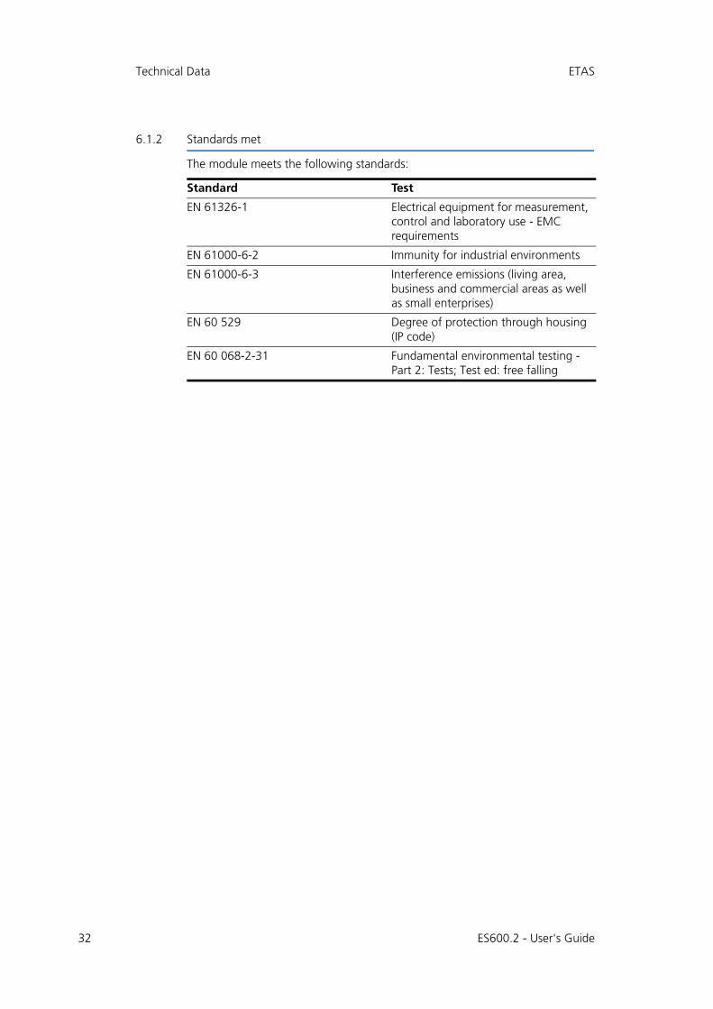
6.1.2 Standards met
The module meets the following standards:
Standard Test
EN 61326-1 Electrical equipment for measurement, control and laboratory use - EMC requirements
EN 61000-6-2 Immunity for industrial environments
EN 61000-6-3 Interference emissions (living area, business and commercial areas as well as small enterprises)
EN 60 529 Degree of protection through housing (IP code)
EN 60 068-2-31 Fundamental environmental testing - Part 2: Tests; Test ed: free falling
ES600.2 - User's Guide
ETAS Technical Data
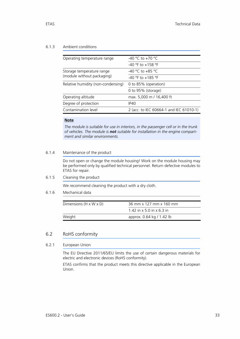
6.1.3 Ambient conditions
6.1.4 Maintenance of the product
Do not open or change the module housing! Work on the module housing maybe performed only by qualified technical personnel. Return defective modules toETAS for repair.
6.1.5 Cleaning the product
We recommend cleaning the product with a dry cloth.
6.1.6 Mechanical data
6.2 RoHS conformity
6.2.1 European Union
The EU Directive 2011/65/EU limits the use of certain dangerous materials forelectric and electronic devices (RoHS conformity).
ETAS confirms that the product meets this directive applicable in the EuropeanUnion.
Operating temperature range -40 °C to +70 °C
-40 °F to +158 °F
Storage temperature range (module without packaging)
-40 °C to +85 °C
-40 °F to +185 °F
Relative humidity (non-condensing) 0 to 85% (operation)
0 to 95% (storage)
Operating altitude max. 5,000 m / 16,400 ft
Degree of protection IP40
Contamination level 2 (acc. to IEC 60664-1 and IEC 61010-1)
Note
The module is suitable for use in interiors, in the passenger cell or in the trunk of vehicles. The module is not suitable for installation in the engine compart-ment and similar environments.
Dimensions (H x W x D) 36 mm x 127 mm x 160 mm
1.42 in x 5.0 in x 6.3 in
Weight approx. 0.64 kg / 1.42 lb
ES600.2 - User's Guide 33

34
Technical Data ETAS
6.2.2 China
ETAS confirms that the product meets the "China RoHS" (Management Meth-ods for Controlling Pollution Caused by Electronic Information Products Regula-tion) guidelines applicable to the People's Republic of China with a China RoHSlabel attached to the product or its packaging.
6.3 CE marking
With the CE mark attached to the product or its packaging, ETAS confirms thatthe product corresponds to the product-specific, applicable European Directives.The CE Declaration of Conformity for the product is available upon request.
6.4 Product return and recycling
The European Union (EU) has issued the guideline on waste electric and elec-tronic equipment (Waste Electrical and Electronic Equipment - WEEE) in order toensure the institution of systems for collection, handling, and disposal of all elec-tronic scrap.
This ensures that the devices are recycled in a resource-friendly way that does notrepresent any risk to personal health and the environment.
Fig. 6-1 WEEE symbol
The WEEE symbol (see Fig. 6-1 on page 34) on the product or its packaging iden-tifies that the product may not be disposed of together with the remaining trash.
The user is obligated to separate the waste equipment and to provide it to theWEEE return system for reuse.
The WEEE Directive applies to all ETAS devices, but not to external cables or bat-teries.
Additional information about the recycling program of ETAS GmbH is availablefrom the ETAS sales and service locations (see chapter 9 on page 50).
6.5 Use of Open Source software
The product uses Open Source Software (OSS). This software is installed in theproduct at the time of delivery and does not have to be installed or updated bythe user. Reference shall be made to the use of the software in order to fulfillOSS licensing terms. Additional information is available in the document "OSSAttributions List" at the ETAS website www.etas.com.
ES600.2 - User's Guide

ETAS Technical Data
6.6 System requirements
6.6.1 Hardware
Operating the ES600.2 requires a DC voltage supply of 7 V to 29 V DC.
PC with an Ethernet interface
Operating the modules requires a PC with an open Ethernet interface (100 Mbit/s for connection to the FE-HOST or 1000 Mbit/s for connection to the GE-HOST,full duplex) with RJ-45 connection.
Prerequisite for successful initialization of the module
Deactivating the power-save mode:
In Control Panel / Device Manager / Network Adapter, select the networkadapter used with a double-click. On the "Power Management" tab, deactivatethe option "Allow the computer to turn off this device to save power“. Confirmyour configuration.
The manufacturers of the network adapters provide different names for thisfunction.
Example:
• "Link down Power saving"
• "Allow the computer to turn off this device to save power."
6.6.2 Supported applications and software prerequisites
The firmware of the ES600.2 can be updated by the user so that future versionsof the module can also be used. The firmware update is done with the help ofthe service software "Hardware Service Pack" (HSP) from the connected PC.
Note
It is absolutely necessary to deactivate the function for automatic switching to power-save mode of your PC network adapter if there is no data traffic at the Ethernet interface!
Note
During a firmware update, neither the voltage supply nor the Ethernet connec-tion may be interrupted!
ES600.2 - User's Guide 35

36
Technical Data ETAS
6.7 Electrical data
6.7.1 Voltage supply
Operating voltage 7 V to 29 V DC
Current consumption, operation 1) Typ. 210 mA at 14.4 V DC
Current consumption, standby 1) Typ. 60 mA at 14.4 V DC
Current consumption, maximum 14 A
Power supply of connected modules Each "ETH" connection: nom. max. 2 A
Energy management On/Off with Start/Stop of Ethernet data transfer (On/Off upstream module)
Protection Reverse polarity-protected and load dump protection in accordance with ISO 16750-2 Test B (central load dump pro-tection required)
1): without power supply of connected modules
ES600.2 - User's Guide

ETAS Technical Data
6.7.2 "GE-HOST" connection
6.7.3 "FE-HOST" connection
Connection type Upstream
Number 1 (GE-HOST)
Connection 10Base-T/100Base-TX/1000Base-T Ether-net
Compatibility PC
ES8xx modules
Note
For the successful initialization of the network card of your PC, observe chapter 6.6.1 on page 35.
Connection type Upstream
Number 1 (FE-HOST)
Connection 10Base-T/100Base-TX Ethernet
Synchronization resolution 1 s
Compatibility 1) PC
ES720 Drive Recorder
Network and interface modules: ES51x, ES592, ES593-D, ES595, ES600.1, ES600.2, ES8xx, ES910
1): Support of ETAS synchronization mechanism
Note
For the successful initialization of the network card of your PC, observe chapter 6.6.1 on page 35.
ES600.2 - User's Guide 37

38
Technical Data ETAS
6.7.4 Ethernet connections "ETH1" to "ETH6"
Connection type Downstream
Number 6 (ETH1, ETH2, ETH3, ETH4, ETH5, ETH6)
Connection 10Base-T/100Base-TX Ethernet
Synchronization resolution 1 s
Nom. max. output current for each "ETH" connection
2 A
Power supply of connected modules ES4xx and ES6xx measuring modules
Compatibility 1) Network module: ES600
Network and interface modules: ES51x, ES592, ES593-D, ES595
Measuring modules:ES4xx, ES6xx, ES930.1
Prototyping and interface module:ES910.3
ECUs with XETK,ECUs with Ethernet interface
Ethernet devices from third parties 2)
1): Support of ETAS synchronization mechanism2): No support of ETAS synchronization mechanism
ES600.2 - User's Guide

ETAS Technical Data
6.8 Terminal assignment
6.8.1 Connection "7-29 V"
Fig. 6-2 Connection "7-29 V"
6.8.2 "FE-HOST" connection
Fig. 6-3 "FE-HOST" connection
Note
All connections are represented with view onto the interfaces of the ES600.2.All shields are on housing potential.
Pin Signal Meaning
1 UBATT+ Supply voltage, positive
2 Ground Ground
Pin Signal Meaning
1 - Reserved
2 - Reserved
3 - Reserved
4 RX+ Receiving data, positive
5 TX- Transmitting data, negative
6 RX- Receiving data, negative
7 - Reserved
8 TX+ Transmitting data, positive
2
1
1 8
ES600.2 - User's Guide 39

40
Technical Data ETAS
6.8.3 "GE-HOST" connection
Fig. 6-4 "GE-HOST" connection
6.8.4 Connections "ETH1" to "ETH6"
Fig. 6-5 Connections "ETH1" to "ETH6"
Pin Signal Meaning
1 BI_DA+
2 BI_DA-
3 BI_DB+
4 BI_DC+
5 BI_DC-
6 BI_DB-
7 BI_DD+
8 BI_DD-
9 N.C. Not connected
10 N.C. Not connected
Pin Signal Meaning
1 UBATT+ Supply voltage, positive
2 UBATT+ Supply voltage, positive
3 UBATT- Supply voltage, negative
4 RX+ Receiving data, positive
5 TX- Transmitting data, negative
6 RX- Receiving data, negative
7 UBATT- Supply voltage, negative
8 TX+ Transmitting data, positive
18
10
9
1 8
ES600.2 - User's Guide

ETAS Cables and Accessories
7 Cables and Accessories
The "Cables and Accessories" chapter provides an overview of available cablesand accessories.
7.1 Cable for the "7-29 V DC" connection
Power supply cables suitable for the ES600.2 module can be delivered in twodesigns:
• power supply cable CBP120 with standard banana plugs (current design) and
• power supply cable CBP1205 with safety banana plugs (new design).
Note
Only the ETAS cables listed in this User's Guide may be used at the interfaces of the ES600.2. The maximum permissible cable lengths must be maintained.
Note
If you need customized cables, please contact your ETAS contact partner or [email protected].
DANGER!
Dangerous electrical voltage!Connect the power cable only with a suitable vehicle battery or with a suitable lab power supply! The connection to power outlets is not allowed!To prevent an inadvertent insertion in power outlets, ETAS recom-mends to equip the power cables with safety banana plugs CBP1205 in areas with power outlets.
Note
Application, permissible voltages and all the other technical data of the power supply cables are identical for both designs.
ES600.2 - User's Guide 41

42
Cables and Accessories ETAS
7.1.1 CBP120 Cable
Fig. 7-1 Cable CBP120-2 (power supply cable with standard banana plugs)
Side A Side B
Side A Side B
Pin Signal Plug Signal
1 UBATT- Red UBATT-
2 Ground Black Ground
Order name Short name Ordernumber
Power Supply Cable, Lemo 1B FGJ Banana (2fc-2mc), 2 m
CBP120-2 F 00K 102 584
ES600.2 - User's Guide

ETAS Cables and Accessories
7.1.2 CBP1205 Cable
Fig. 7-2 Cable CBP1205 (power supply cable with safety banana plugs)
Side A Side B
Side A Side B
Pin Signal Plug Signal
1 UBATT Red UBATT
2 Ground Black Ground
Order Name Short name Order Number
Power Supply Cable, Lemo 1B FGJ – Safety Banana (2fc-2mc), 2 m
CBP1205-2 F 00K 110 023
Note
Power supply cables with safety banana plug are suitable only for connection to voltage sources with safety socket.
ES600.2 - User's Guide 43
44
Cables and Accessories ETAS
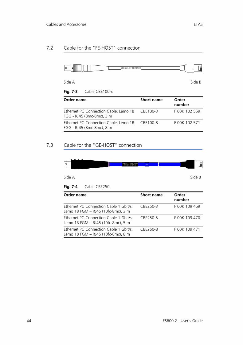
7.2 Cable for the "FE-HOST" connection
Fig. 7-3 Cable CBE100-x
7.3 Cable for the "GE-HOST" connection
Fig. 7-4 Cable CBE250
Side A Side B
Order name Short name Ordernumber
Ethernet PC Connection Cable, Lemo 1B FGG - RJ45 (8mc-8mc), 3 m
CBE100-3 F 00K 102 559
Ethernet PC Connection Cable, Lemo 1B FGG - RJ45 (8mc-8mc), 8 m
CBE100-8 F 00K 102 571
Side A Side B
Order name Short name Ordernumber
Ethernet PC Connection Cable 1 Gbit/s, Lemo 1B FGM – RJ45 (10fc-8mc), 3 m
CBE250-3 F 00K 109 469
Ethernet PC Connection Cable 1 Gbit/s, Lemo 1B FGM – RJ45 (10fc-8mc), 5 m
CBE250-5 F 00K 109 470
Ethernet PC Connection Cable 1 Gbit/s, Lemo 1B FGM – RJ45 (10fc-8mc), 8 m
CBE250-8 F 00K 109 471
CBE250.1-x F 00K 109 4xxGIGABIT ETHERNET 0000
ES600.2 - User's Guide

ETAS Cables and Accessories
7.4 Cable for the connections "ETH1" to "ETH6"
7.4.1 Cable CBE130-x
Fig. 7-5 Cable CBE130-x
7.4.2 Cable CBE140
Fig. 7-6 Cable CBE140-0m45
Side A Side B
Order name Short name Ordernumber
Ethernet Connection and Power Supply Cable, Lemo 1B FGF Lemo 1B FGD (8mc-8mc), 0m45
CBE130-0m45 F 00K 102 748
Ethernet Connection and Power Supply Cable, Lemo 1B FGF Lemo 1B FGD (8mc-8mc), 3 m
CBE130-3 F 00K 102 587
Side A Side B
Order name Short name Ordernumber
Ethernet Connection and Power Supply Cable, Lemo 1B FGF Lemo 1B FGD (8mc-8mc), 0m45
CBE140-0m45 F 00K 104 153
ES600.2 - User's Guide 45

46
Cables and Accessories ETAS
7.4.3 Adapter cable
Fig. 7-7 Cable CBAE330.2
Side A Side B
Order name Short name Ordernumber
Ethernet Connection Adapter Cable 1 Gbit/s to 100 Mbit/s, Lemo 1B PHE - Lemo 1B FGF (10fc-8mc), 0m5
CBAE330-0m5 F 00K 105 759
ES600.2 - User's Guide

ETAS Order Information
8 Order Information
8.1 ES600.2
8.1.1 ES600.2 with CBP120 Power Supply Cable
8.1.2 ES600.2 with CBP1205 Power Supply Cable
Order Name Short Name Order Number
ES600.2 Synchronization and Power Man-agement Module
ES600.2 F 00K 109 493
Package Contents
ES600.2 Synchronization and Power Man-agement Module, Cable CBE100-3, CBP120-2, T-Bracket for Housing, ES523_CD, List "Content of this Package", QNX Licence with AP for ES5xx, ES5xx Premium Line Safety Advice, China-RoHS-leaflet_Compact_green_cn
Order Name Short Name Order Number
ES600.2 Synchronization and Power Man-agement Module with Safety Cable
ES600.2-S F 00K 110 453
Package Contents
ES600.2 Synchronization and Power Man-agement Module, Cable CBE100-3, CBP1205-2, T-Bracket for Housing, ES523_CD, List "Content of this Package", QNX Licence with AP for ES5xx, ES5xx Premium Line Safety Advice, China-RoHS-leaflet_Compact_green_cn
ES600.2 - User's Guide 47

48
Order Information ETAS
8.2 Accessories
8.2.1 Cable
Cable for the "7-29 V DC" connection
Cable for the "FE-HOST" connection
Cable for the "GE-HOST" connection
Cable for the connections "ETH1" to "ETH6"
Note
If you need customized cables, please contact your ETAS contact partner or [email protected].
Order Name Short Name Order Number
Power Supply Cable, Lemo 1B FGJ Banana (2fc-2mc), 2 m
CBP120-2 F 00K 102 584
Power Supply Cable, Lemo 1B FGJ – Safety Banana (2fc-2mc), 2 m
CBP1205-2 F 00K 110 023
Order Name Short Name Order Number
Ethernet PC Connection Cable, Lemo 1B FGG - RJ45 (8mc-8mc), 3 m
CBE100-3 F 00K 102 559
Ethernet PC Connection Cable, Lemo 1B FGG - RJ45 (8mc-8mc), 8 m
CBE100-8 F 00K 102 571
Order Name Short Name Order Number
Ethernet PC Connection Cable 1 Gbit/s, Lemo 1B FGM – RJ45 (10fc-8mc), 3 m
CBE250-3 F 00K 109 469
Ethernet PC Connection Cable 1 Gbit/s, Lemo 1B FGM – RJ45 (10fc-8mc), 5 m
CBE250-5 F 00K 109 470
Ethernet PC Connection Cable 1 Gbit/s, Lemo 1B FGM – RJ45 (10fc-8mc), 8 m
CBE250-8 F 00K 109 471
Order Name Short Name Order Number
Ethernet Connection and Power Supply Cable, Lemo 1B FGF Lemo 1B FGD (8mc-8mc), 0m45
CBE130-0m45 F 00K 102 748
ES600.2 - User's Guide

ETAS Order Information
8.2.2 Housing accessories
Ethernet Connection and Power Supply Cable, Lemo 1B FGF Lemo 1B FGD (8mc-8mc), 3 m
CBE130-3 F 00K 102 587
Ethernet Connection and Power Supply Cable, Lemo 1B FGF Lemo 1B FGD (8mc-8mc), 0m45
CBE140-0m45 F 00K 104 153
Ethernet Connection Adapter Cable 1 Gbit/s to 100 Mbit/s, Lemo 1B PHE - Lemo 1B FGF (10fc-8mc), 0m5
CBAE330-0m5 F 00K 105 759
Order Name Short Name Order Number
T-connector for ES600 housing ES600_H_TB F-00K-001-925
Device feet ES600_H_F F-00K-001-924
Order Name Short Name Order Number
ES600.2 - User's Guide 49

ES600.2 - User's Guide50
ETAS Contact Addresses ETAS
9 ETAS Contact Addresses
ETAS HQ
ETAS GmbH
ETAS Subsidiaries and Technical Support
For details of your local sales office as well as your local technical support teamand product hotlines, take a look at the ETAS website:
Borsigstraße 14 Phone: +49 711 3423-0
70469 Stuttgart Fax: +49 711 3423-2106
Germany WWW: www.etas.com
ETAS subsidiaries WWW: www.etas.com/en/contact.php
ETAS technical support WWW: www.etas.com/en/hotlines.php

ETAS Figures
Figures
Fig. 3-1 ES600.2 Synchronization and Power Management Module......................... 13Fig. 3-2 ES600.2 front side of device ....................................................................... 15Fig. 3-3 ES600.2 rear side of device ......................................................................... 15Fig. 4-1 Block diagram............................................................................................. 19Fig. 5-1 Prying off the plastic foot............................................................................ 23Fig. 5-2 Blind hole with thread .............................................................................. 24Fig. 5-3 Connecting the ES600.2 with another module............................................ 25Fig. 5-4 Cabling of ES600.2 with ETAS modules (MC application)............................ 26Fig. 6-1 WEEE symbol.............................................................................................. 34Fig. 6-2 Connection "7-29 V" ................................................................................ 39Fig. 6-3 "FE-HOST" connection .............................................................................. 39Fig. 6-4 "GE-HOST" connection ............................................................................. 40Fig. 6-5 Connections "ETH1" to "ETH6" ................................................................ 40Fig. 7-1 Cable CBP120-2 (power supply cable with standard banana plugs)............. 42Fig. 7-2 Cable CBP1205 (power supply cable with safety banana plugs) .................. 43Fig. 7-3 Cable CBE100-x ......................................................................................... 44Fig. 7-4 Cable CBE250 ........................................................................................... 44Fig. 7-5 Cable CBE130-x ......................................................................................... 45Fig. 7-6 Cable CBE140-0m45 ................................................................................. 45Fig. 7-7 Cable CBAE330.2 ...................................................................................... 46ES600.2 - User's Guide 51

52
Figures ETAS
ES600.2 - User's Guide

ETAS Index
Index
AAccessories 41Accident prevention 9Ambient temperature 33Applications 26Software prerequisites 35
BBlock diagram 19
CCable 41
CBAE330.2 46CBE100-x 44CBE130-x 45CBE140-0m45 45CBE250 44CBP120-2 42CBP1205 43
Cabling 26, 27Carrier system 23Cascadability 21CE Declaration of Conformity 34Compatibility 37, 38Connect
Housing 24
DData
electrical 36mechanical 33technical 31
Device foot 49Documentation 9
EElectrical data 36Electrical safety 10ES600_H_F 49ES600_H_TB 49ETAS Contact Addresses 50ETAS device synchronization 21Ethernet interface 38, 40Ethernet switch
Properties 20
FFirmware update 22Front side of device 15Functional Description 19
HHardware, system requirements 35Host interface 37Housing
Connect 24fixing 23
ES600.2 - User's Guide 53

54
Index ETAS
HSP 22, 35
IIdentifying the product 31Indicators 16Initialization 35
LLink signal detector 21
MM3 cylinder screw 24Mechanical data 33Module compound 21Modules
joining 24
OOperation
Conventions 8Use Case 7
PPC network adapter 35Phase shift 21Plastic foot 23Power supply 19, 36Power supply of connected modules
21Presentation of information 7Product
Exclusion of liability 9Product return 34Properties
Ethernet switch 20
QQualification, required 9
RRear side of device 15Recycling 34RoHS conformity
China 34European Union 33
SSafety at work 9, 10Safety notices
basic 9Identification 7
Safety precautions 9
Scope of supply 8Screw thread 23Screw-in depth 24Standards 32Supply Voltage 36SYNC-IN 21SYNC-OUT 21System requirements 35
TT-connector 24, 49Technical data 31Terminal assignment 39Time clock 21Time synchronization unit 21
UUse, intended 9
VVoltage supply 36
WWake-Up function 21, 22Waste Electrical and Electronic Equip-
ment - WEEE 34WEEE return system 34
ES600.2 - User's Guide