evaluation of cad/cam generated …d-scholarship.pitt.edu/30630/1/delsazsultan_etd2016.pdfevaluation...
TRANSCRIPT

EVALUATION OF CAD/CAM GENERATED CERAMIC POST & CORE
by
Delsaz Sultan
DMD, Boston University, 2013
Submitted to the Graduate Faculty of
THE SCHOOL OF DENTAL MEDICINE in partial fulfillment
of the requirements for the degree of
Master of Dental Science
University of Pittsburgh
2016
ii
UNIVERSITY OF PITTSBURGH
SCHOOL OF DENTAL MEDICINE
This thesis was presented
by
Delsaz Sultan
It was defended on
September23, 2016
and approved by
Dr. Mohsen Azarbal,DMD,MDS, Associate Professor Department of Prosthodontics
Dr. Thomas Kunkel,BS,DMD, Assistant Professor Department of Prosthodontics
Dr. Nilesh Shah,BS,PHD, Assistant Professor Department of Dental Public Health
Dr. Robert Engelmeier, BS,DMD,MS,Professor /chair Department of Prosthodontics

iii
Copyright © by Delsaz Sultan
2016

iv
Objective
The purpose of this study was to evaluate the use of CAD/CAM technology as a method
to fabricate a single-unit, all-ceramic Post & Core restoration.
Materials and Methods
Three master dies were fabricated from polymer material (Acadental T Endo TM series
RT _AE401_08 ®). The coronal part of the die simulated an ideal core preparation with a 1.5 to
2mm ferrule. The intracanal space of the first die was prepared for a post length of 5mm. The
intracanal space for the second die was prepared for a post length of 10mm. Finally, the
intracanal space for the third die was prepared to a length of 14mm. Each die was scanned 20
times using the Sirona CEREC AC BlueCam®. A total of sixty e.max® CAD/CAM post and
core restorations were milled using Sirona CEREC three compact milling unit®. The restorations
were evaluated for precision of fit using 2 methods:
1. The marginal gap was measured for each Post & Core restoration using scanning electron
microscopy to determine the accuracy of fit of the core to the die. Measurements were made at
three points: mesial, buccal and distal of each sample. The mean marginal gap for the three
groups was 38 um.
Evaluation of CAD/CAM generated ceramic Post & Core
Delsaz Sultan, DMD,MS
University of Pittsburgh, 2016

v
2. A radiograph was taken of each of the 60 samples to determine the post length. The mean
post length for the group that was calibrated for 5mm was 6.3mm. Mean post length for the
group that was calibrated for 10mm was 10.0mm. Mean post length for the group that was
calibrated for 14mm was 11.0mm. Overall, there was no pattern of relationship between
marginal gap and post length among the three groups.
Conclusion
This study concluded that the focal working length of Sirona CEREC AC® BlueCam is
accurate up to 13.7mm. However, the technology is not able to consistently produce accurate
milled post and core restorations beyond 11mm. The mean marginal gap for the three groups was
38 um. Future studies are needed to evaluate the biomechanical properties of ceramic Post &
Core restorations.

vi
TABLE OF CONTENTS
TABLE OF CONTENTS ................................................................................................. vi
List of tables ................................................................................................................... viii
List of figures .................................................................................................................... ix
ACKNOWLEDGMENTS ................................................................................................ xi
1.0 INTRODUCTION .................................................................................................... 1
2.0 RESEARCH OBJECTIVES .................................................................................... 5
3.0 RESEARCH HYPOTHESIS ................................................................................... 6
3.1 Null hypothesis ...................................................................................................................... 6
3.2 Alternative hypothesis .......................................................................................................... 6
4.0 REVIEW OF LITERATURE ................................................................................. 7
5.0 DIGITAL DENTISTRY ........................................................................................ 10
6.0 INTRAORAL SCANNERS ................................................................................... 12
7.0 SOFTWARE ........................................................................................................... 14
8.0 processing DEVICE ................................................................................................ 15
8.1 Milling variant ..................................................................................................................... 16

vii
8.2 CEREC System .................................................................................................................... 17
9.0 MATERIALS FOR CAD/CAM PROCESSING ................................................. 19
9.1 Metals ................................................................................................................................... 19
9.2 Resin Materials .................................................................................................................... 19
9.2.1 Composite Resin for Permanent Restorations ......................................................... 19
9.2.2 Composite Resin for Temporary Materials .............................................................. 20
9.3 Ceramics ............................................................................................................................... 20
10.0 NANOCERAMICS .............................................................................................. 26
11.0 Review Marginal and internal Fit for CAD/CAM Generated Ceramic
Crowns…………………………………………………………………………………………..27
12.0 Review of Method of Measurement Marginal Gap .......................................... 29
13.0 Influence of Sample Size ..................................................................................... 31
14.0 MATERIALS AND METHODS ........................................................................ 32
15.0 Measurement of Precision and Fit ..................................................................... 34
16.0 STATISTICAL ANALYSIS ............................................................................... 36
17.0 RESULTS ............................................................................................................. 37
18.0 DISCUSSION ....................................................................................................... 45
19.0 CONCLUSION .................................................................................................... 52
20.0 FIGURES ............................................................................................................. 53
BIBLIOGRAPHY............................................................................................................77

viii
LIST OF TABLES
Table 1. Dental Ceramics Classification.......................................................................................21
Table 2. Physical Properties IPS emax………………………………………………………….24
Table 3. One sample T test Group A……………………………………………………………38
Table 4. One sample T test Group B…………………………………………………………….39
Table 5. One sample T test Group C…………………………………………………………….40
Table 6. Histogram Post Length………………………………………………………………...41
Table 7. Histogram Mesial Marginal Gap………………………………………………………42
Table 8. Histogram Buccal Marginal Gap………………………………………………………43
Table 9. Histogram Distal Marginal Gap………………………………………………………..44

ix
LIST OF FIGURES
Figure 1. Die mounted on the scannable model……...……………..…………………………...53
Figure 2. (a) and (b) Die prepared using survey handpiece……………………………………..54
Figure 3. CEREC three BlueCam® and compact milling machine……………………………..55
Figure 4. CEREC software 4.0………………………………………………………………….56
Figure 5. Optoelectronic scanning of post space…………………………………………..…....56
Figure 6. Restoration parameter…………………………………………………………………57
Figure 7. 5.8mm post space and post restoration measured with 4.0 CERE................................57
Figure 8. 6mm post space measured with CEREC® software 4.0……………………………...58
Figure 9. Front view pre milling 5mm post (a) and side view pre milling 5mm post (b)…........58
Figure 10. Ceramic firing furnace…………………………………………………………….…59
Figure 11. Compact milling machine fabricating the post………………………………………60
Figure 12. 10mm post space and proposed post and core…………………………………….…60
Figure13. 10mm post space depth measured with 4.0 CEREC®……………………………….61
Figure 14. Pre-milling proposal for 10mm Post & Core (a) and side view pre milling proposal
for 10mm post and core………………………………………………………...…...61
Figure 15. Group C post space 14mm proposed post and core 11mm (a) and Group C post
space (b)………………………………………………………………………….....62

x
Figure 16. Group C 11mm post front view pre milling proposal (a) and Group C 11mm post side
view pre milling proposal (b)………………………………………………………...63
Figure 17. Die D 15mm camera wasn’t able to read the end working length point…………….64
Figure 18. Die D software proposing a restoration of the core side view only (a) and Die D
software proposing a restoration of the core front view only
(b)……………………………….................................................................................65
Figure 19. Die D milling proposal of the core front view only (a) and milling proposal of the
core front view only………………………………..............………………………...66
Figure 20. JSM -6610LV ® scanning electron microscope (a) and marginal gap micrograph
process using the software (b)…………………………………………..................…67
Figure 21. Sample holder stage (a) and (b)……………………………………………………...68
Figure 22. The three groups sample mounted A on the far right and C on the far left………….69
Figure 23. Sample inside SEM chamber (a) and mounted sample inside SEM chamber……….70
Figure 24. Sample 17 Group C mesial point measurement at X200 (a) sample 17 Group C mesial
point measurement (b)………………………………….........................………….71
Figure 25. Sample 19 Group C buccal point measurement (a) and sample 19 Group C buccal
point measurement (b)………………………………………………..............……...72
Figure 26. Sample 15 Group B mesial point…………………………………………………….73
Figure 27. Sample 15 Group B mesial point…………………………………………………….73
Figure 28. Die mounted for radiograph (a) and die mounted for radiograph capturing (b).........74
Figure 29. Mipax® x-ray software radiograph………………………………………………….75
Figure 30. Example of the restoration milled for Groups A, B and C…………………………..75
Figure 31. mm Caliper…………………………………………………………………………..76

xi
ACKNOWLEDGMENTS
I would like to express my deepest appreciation to the committee Chair, Dr. Robert Leo
Engelmeier, whose guidance and assistance made this master thesis possible. I would like to
thank committee members Dr. Mohsen Azarbal and Dr. Thomas Craig Kunkel for their
insightful comments and encouragement, as well as Dr. Nilesh Shah for his help with the
research structure and statistical analysis. I extend thanks to Dr. Kevin Pawlo for his
introduction to the Cad/Cam Post & Core methodology, and to Mr. Cole Vanormer from the
University of Pittsburgh Swanson School of Engineering and Mechanical Engineering and the
Material Science Department MMCL Laboratory for his help with the scanning electron
microscope training and the mechanical device invention.
The author declares no conflict of interest with any of the research involved companies.

1
1.0 INTRODUCTION
Endodontically treated teeth show greater risk of failure than their vital counterparts. In
the case of insufficient tooth structure those teeth often need a Post & Core as a foundation for
the final restoration. A Post & Core protects the remaining tooth structure and allows the
restoration of function1.
Post & Core restorations were first introduced to dentistry by the father of modern
dentistry, Pierre Fauchard, in the form of gold and silver posts during the 18th century. They
enabled replacement of missing tooth crowns with porcelain crowns2. The first combined Post &
Core with a porcelain facing was introduced to dentistry by an American dentist “C. M.
Richmond” (1835–1902) and was termed the Richmond crown3.
Post & Core restorations are classified into two main categories: Custom made and
Prefabricated. A cast metal Post & Core is traditionally the treatment of choice to provide the
necessary retention and strength for a final restoration. It is custom fit to the prepared post space.
This can be achieved through an indirect impression of the prepared canal using an elastic
impression material, or through a direct pattern technique4. The restoration of endodontically
treated anterior teeth using cast metal Post & Core underlying all ceramic crowns usually results
in a poor esthetic outcome due to the translucency of ceramics5. A cast metal Post & Core can
usually be used in cases where the crown thickness is more than 1.6mm6. However, according to

2
Nakamura, et al, a single unit zirconia Post & Core is recommended in cases where the ceramic
crown thickness is under 1.6mm7.
Prefabricated glass fiber posts have variable shades, enhanced mechanical properties and
better biocompatibility8,9. Their main disadvantage is that their diameters cannot be customized
to adapt to individual post space preparations. Custom made Posts & Core is indicated in cases
with wide, noncircular, or extremely tapered canals where cylindrical prefabricated posts may
not achieve adequate adaptation of the post to the canal10,11. The weak interface between the
resin core and the fiber post may also increase the risk of failure12. According to a 10-year
retrospective study by Balkenhol, et al., the fit of a cast Post & Core directly influences the
ultimate survival of the restoration13.
The long-term failure rate of fiber posts reportedly ranges from 7 to 11%9,14.. Apart from
endodontic problems the primary reasons for failure include crown dislodgement and post
debonding. Assif and Gorfil15 reported that endodontically treated teeth restored with Post &
Core restorations can produce stresses concentrated at the coronal third of the root and at the
interface between the core and the post. If the modulus of elasticity differs between materials,
there is potential for separation of the core from the post. Such separation is less likely to occur
when the post and the core are composed of the same material16.
A new method of fabricating custom made Post & Core is the use of monoblock zirconia
and all ceramic CAD/CAM technology (computer-aided design/computer-aided manufacturing).
The Post & Core restoration is generated by means of a direct optical impression of the post
space or an indirect impression of a resin pattern or polyvinylsiloxane impression of the post
space4. High-strength ceramics allow fabrication of restorations with optimal esthetics, good
biocompatibility, excellent periodontal tissue response, as well as the necessary mechanical

3
properties to withstand functional stressors. In 1992 Bex, et al.,17 investigated the effect of
dentin-bonded resin post-core restorations on the resistance to vertical root fracture and
concluded that dentin-bonded resin post-core restorations provided significantly less resistance to
failure than cemented custom cast Posts & Cores. In every instance the dentin-bonded resin Posts
& Core fractured before the roots fractured. In 1996 Saupe, et al.,18 compared the fracture
resistance between custom metal cast Posts & Core and a resin-reinforced dowel system for
structurally compromised roots. Their results indicated that resistance to masticatory load of a
resin-reinforced Post & Core system was greater than that of a morphologic Post & Core
restoration. They also reported that when a bonded resin Post & Core was used on structurally
weakened roots there was no statistically significant difference in strength between Post & Core
restorations that used a ferrule and those that did not.
Fabricating the Post & Core as a single unit decreases the frequency of failure, which
offers advantages over multiple unit Post & Cores. Fasbinder et al.,19 found that the use of digital
impressions was more efficient than the traditional time involved in making impressions and
pouring casts. One recent study reported that scanning was 10 minutes faster than conventional
impressions for single abutments and short span fixed partial dentures19,20. Multiple studies have
shown increased restoration quality and marginal fit with CAD-CAM systems. Another
noteworthy study24,19 examined over 1000 crowns made with polyvinyl-siloxane impressions.
After 5 years of clinical service they reported that a marginal gap of less than 120 microns is
clinically acceptable for cemented restorations. Digital systems have been reported to fabricate
restorations with marginal fit with less marginal gap than this standard. One laboratory study21
measured the fit of CEREC® crowns compared with those fabricated using conventional
laboratory techniques. There was no significant difference in crown margin fit between the chair
4
side CAD/CAM and the laboratory fabricated techniques. The CEREC crowns had a mean
margin gap of 65.5 ± 24.7 microns for ceramic crowns and 66.0 ± 14.1 microns for composite
crowns21, 19. An in vitro study compared the accuracy of full ceramic crowns obtained from
intraoral scans using Lava COS®, CEREC AC®, and iTero® systems with two different
conventional impression techniques. The mean margin fit of the crowns was 48 microns for Lava
COS®, 30 microns for CEREC AC®, 41 microns for iTero®, 33 microns for single-step putty
wash technique and 60 microns for the two-step putty wash technique22. The mean internal fit
was 29 microns for Lava COS®, 88 microns for CEREC AC®, 50 microns for iTero®, 36
microns for single-step putty wash technique, and 35 for two-step putty wash technique. There
was no significant difference in the margin fit or internal adaptation of the crowns using any of
the previously mentioned techniques.

5
2.0 RESEARCH OBJECTIVES
This study evaluated the use of chair side, CAD/CAM technology as a method to
fabricate single-unit all-ceramic Post & Core restoration utilizing a direct optoelectronic
scanning impression of the post space 150,151.

6
3.0 RESEARCH HYPOTHESIS
3.1 Null hypothesis
Chair side CAD/CAM technology (Sirona CEREC BlueCam®) cannot produce direct
single unit all ceramic Post & Core restorations with a canal depth of 10mm.
3.2 Alternative hypothesis
Chair side CAD/CAM technology (Sirona CEREC BlueCam®) can produce direct single
unit all ceramic Post & Core restoration up to 10mm of intracanal depth.

7
4.0 REVIEW OF LITERATURE
The purpose of the post is to retain a core needed to support a crown restoration due to
the extensive loss of tooth structure. Preparation of a post space should be relevant to that need.
Multiple guidelines for post length can be found in literature: the post length should equal the
incisocervical or occlusocervical dimension of the crown25,26,27,28,29,30,31,32; the post should be
longer than the crown33; the post should be one and one-third of the crown length34; the post
should be one-half of the root length35,36; the post should be two-thirds of the root
length37,38,39,40,41; the post should be four-fifths of the root length42; The post should be
terminated halfway between the crestal bone and root apex43,44,45; the post should be as long as
possible without disturbing the apical seal46.
According to current endodontic textbooks47 about 4mm of gutta-percha is needed to
provide an appropriate apical seal. Because of variation in the angulation of radiograph, it is
prudent to leave 5mm or more gutta percha as it appears on a radiograph47,48,49. For the anterior
and bicuspid teeth the recommendation is for 5mm of apical gutta-percha, and that the post
should extend to that level. The recommendation for molar teeth is determined by the potential
for root perforation. Posts in molars should be extended only 5mm into the canal
length47,50. After measuring 700 teeth Shillingburg, et al., noted that making the post length
equal to the clinical crown length causes the post in some teeth to encroach on the 4mm “safety
zone”51. Zillich and Corcoran presented data comparing length guidelines to average, long, and

8
short root lengths and the need to retain adequate apical seal. When posts were one-half of the
root length the endodontic seal of 5mm was rarely compromised on average roots. When posts
were two-thirds of the root length many of the average and short root length teeth had
compromised apical seals. When posts were equal to the crown length an adequate seal was only
possible on teeth with average or long root lengths. With short-rooted teeth even the shorter post
guideline of being equal to the crown length produced a compromised apical seal. They did not
calculate data for posts as long as three-fourths of the root length61. A second criterion in the
post preparation is post diameter. It should not be more than one third of the root diameter and
should be minimally apical52,53..
Another key guideline in post development is the ferrule. It amounts to a circumferential
band of metal that wraps the tooth structure, and is the key element preventing future tooth
fracture. The crown ferrule ideally should cover more than 1mm of tooth structure54. A ferrule
that engages 2mm of tooth structure around the entire circumference provides greater fracture
resistance55,56.
Post & core restorations are classified into two broad categories: Custom made and
prefabricated. Cast metal Post & Core is custom made and is traditionally the treatment of choice
to provide the necessary retention for a final restoration. It is designed to provide a custom fit to
the prepared post space. Other attributes of cast Post & Core restorations are high durability,
strength and the strong monoblock union between the core and the post. However, they have
been associated with deep root fracture due to their higher modulus of elasticity than dentin57.
The fiber reinforced Post & Core restorations offers improved esthetics and more favorable
stress distribution58. Overall, the cast Post & Core is still superior in situations where teeth have

9
suffered extensive damage, serve as an abutment for fixed partial denture, or in bruxism
situations. Cast Post & Core restorations can be fabricated indirectly by means of an impression
of the prepared canal using an elastic impression material or directly via a resin pattern
technique4. Another method of fabricating a custom made Post & Core is the use of CAD/CAM
technology to generate the Post & Core restoration from a ceramic block4.
Prefabricated posts made of metal, carbon or fiber reinforced allow more desirable shades
and enhanced biocompatible properties. This can be attributed to their compatible modulus of
elasticity to dentin and luting cements which decrease the stresses and the risk of root
fracture8,9,60. Moreover pre-fabricated posts allow for shorter dental visits. The main
disadvantage of the pre-fabricated posts is that their diameters cannot be customized to adapt to
individual post space preparations which can be very wide, noncircular, or have extremely
tapered canals. This can compromise retention10,11.
A weak interface between the resin core and the fiber post may increase the risk of
failure12. A 10-year retrospective study by Balkenhol, et al., revealed that the fit of a cast Post &
Core directly influences the survival of the restoration13.
10
5.0 DIGITAL DENTISTRY
Digital dentistry is a term used to describe the clinical application of Computer Assisted
Design/Computer Assisted Machining (CAD/CAM)62,63. All CAD/CAM systems consist of
three components64:
1. A digitalization tool/scanner that transforms geometry into digital data that can be
processed by a computer.
2. Software that processes the data and produces a data set which can be used in the fabrication
of a product.
3. Production hardware that transforms the data set into the desired product.
First, the patient’s intraoral condition is recorded using an intraoral camera or scanning
device to capture a digital file of the dentition. The software program is then used to manipulate
the data and to design the desired restoration. It enables alteration of the parameters and
morphology of the restoration to a desired design. After the design has been finalized, a
machining device is used to mill the planned restoration. Most machining methods are
subtractive. The final restoration is cut from a preformed block of restorative material in a
milling chamber63. The first two parts of the system play roles in the CAD phase, while the third
makes up the CAM phase.
11
CAD/CAM systems can be divided into two classifications based on their digital data
sharing capacity65. Closed systems offer all CAD/CAM procedures, including data collection,
virtual restoration design and fabrication. All steps are enclosed within the system. There is no
interchangeability or exchange between different systems. Open systems allow sharing of
original digital data with other CAD software and CAM devices66. Another classification
depends on the location of the components of the CAD/CAM system. In dentistry three different
production concepts are available:
1. Chairside Production-All components of the CAD/CAM system are located in the dental
treatment area. Fabrication of dental restorations take place at the chair side without laboratory
support.
2. Laboratory Production-The dentist sends an impression to a laboratory where a master cast is
fabricated first. The remaining CAD/CAM production steps are carried out entirely at a
laboratory. With the assistance of a scanner, three-dimensional data are produced from the
master die. These data are processed employing dental design software. Following the CAD-
process the data is sent to a special milling device that ultimately produces the restoration.
3. Centralized Production-The third option of computer-assisted production of dental prostheses
is centralized production in a milling Centre. In this variation it is possible for ‘satellite scanners’
in the dental laboratory to be connected with a production Centre via the Internet. Data sets
produced in a dental laboratory are sent to the Production Centre for the restorations to be
generated by a CAD/CAM device. Finally, the production Centre sends the prosthesis to the
responsible laboratory. Production steps 1, and 2 take place in the dental laboratory, while the
third phase takes place at the Centre64,67,68.
12
6.0 INTRA ORAL SCANNERS
There are two primary classifications of intra-oral scanners:
• Single image and video camera
• Optical scanners and mechanical scanners
Single Image and Video Camera Scanners19.
Single image cameras record individual pictures of the dentition. The iTero®, E4D, and
TRIOS® cameras are single-image cameras. The TRIOS® camera records images at such a
rapid rate that it approaches a functional appearance of a video camera. Three teeth can be
included in a single image. To record larger areas of the dentition, a series of overlapping
individual images are registered. The software program can reassemble them into a larger three
dimensional virtual model.
The Lava Chairside Oral Scanner® (COS) was the first video camera available. The True
Definition Camera® is the most recent version of this video camera. The OmniCam® camera
has live color streaming for video recording capability. The function of this camera is similar to
any video camera where the image is recorded as the camera is moved around the dentition. The
more teeth captured in the video recording, the larger is the virtual model created in the software.

13
Both types of computerized systems record the digital files as STL files. An important
consideration is what applications are available with the proprietary. STL file is a specific
proprietary system for records70,71,72,73
Optical Scanners and Mechanical Scanners
An optical scanner collects images of three-dimensional structures utilizing triangulation
procedure. The lasers light source and the receptor unit are at a set angle to one another. A
computer can calculate a three dimensional data set from the images on the receptor unit74,75,76
. Either white light projections or a laser beam can serve as the source of illumination. The
following are examples of current optical scanners:
• Lava Scan ST® (3M ESPE, white light projections)
• Everest Scan® (Kavo, white light projections)
• es1® (Etkon, laser beam).
A mechanical scanner reads the master cast line-by-line using a ruby ball and the three
dimensional structure measured. The Procera Scanner® from Nobel Biocare (Göteborg) is the
only available mechanical scanner. This type of scanner is distinguished by its high scanning
accuracy. The diameter of the ruby ball is set to match the smallest grinder in the milling
system, allowing all data collected by the system to be milled77,78. The data measurement
technique requires complicated mechanics, which makes the apparatus very expensive and
requires long processing times.

14
7.0 SOFTWARE
Software is created by the manufacturer to design several types of dental restorations.
Available software is continually updated. The construction data is available in several formats,
through mostly standard transformation language (STL) data64,79.

15
8.0 PROCESSING DEVICE
CAD software data is converted into milling strips for the CAM processing. Milling
devices are classified according to the number of milling axes:
3-Axis Milling Device:
A 3- axis milling device moves in x, y and z-axis. It also enables 1800 movement. Advantages of
the three axis milling device are short time milling and simplified control
[examples: InLab (Sirona)®, Lava® (3M ESPE), Cercon Brain®(DeguDent)].
4-Axis Milling Device:
In addition to the x, y and z axes, the tension bridge for a 4 axis milling device
component can be turned with infinite variability [example Zeno® (Wieland-Imes)].
5-Axis Milling Devices
Adding to the three dimensional axis dimension and rotatable tension bridge (4th axis),
the 5 axis milling device has the possibility of rotating the milling spindle (5th axis). These
machines enable milling of complicated geometry (eg.), in the laboratory area: Ever-est Engine
(Kavo®), in the production center: HSC milling device (Etkon®)64. Restorations milled with a
16
5-axial milling unit have greater accuracy than those milled with a 4-axial milling unit because
5-axial milling unit can mill undercuts in all directions 80.
8.1 Milling variant 64
Dry processing is mostly used with zirconia oxide with a low degree of pre-
sintering. Advantages include: low cost for the milling device, no moisture absorption by
the Zro2 die mold which eliminates drying time before sintering. However, the low degree of
pre-sintering causes higher shrinkage of the framework.
In wet milling the cutting bur is cooled by a spray of cold liquid to prevent
overheating of the milled material. Wet milling is needed for all metals and glass ceramic
material to prevent damage from heat. It is recommended in cases where zirconium oxide
ceramic has a higher degree of pre-sintering. A high degree of pre-sintering reduces shrinkage
and provides less sinter distortion [example: InLab (Sirona®), Zeno 8060(Wieland –Imes®) and
Everest (Kavo®)]. Intraoral digital impression systems vary in their key features such as
working principle, light source, the necessity of powder coat spraying, operative process and
output file format. Systems currently available include:
1- CEREC system®
2- Lava C.O.S system®
3- iTero system®
4- E4D system®

17
5- TRIOS system®
8.2 CEREC System
The CEREC 1 System® (Sirona, Bensheim, Germany) was introduced in 1987. Its Duret
system was the first intraoral digital impression and CAD/CAM device81. The concept in which
the intersection of three linear light beams is concentrated on a particular point in space is known
as triangulation of light69. Surfaces with different light dispersion decreases the accuracy of such
scans. As a result the use of an opaque titanium dioxide powder coating is needed to increase
scan accuracy82.
Currently the most predominant CEREC® system is its fourth generation product,
CEREC AC BlueCam®. It records images using a visible blue light emitted from an LED blue
diode as its light source. The CEREC AC BlueCam® can capture one quadrant of the digital
impression within 1 minute and the antagonist in a few seconds. The newest CEREC system®,
CEREC AC Omnicam, was marketed in 2012. BlueCam® imaging is a single image acquisition
technique. The Omnicam® imaging technology is a continuous imaging mode. It captures and
generates a 3D model. The BlueCam® can be applied to a single tooth as well as a quadrant. The
Omnicm® can be used for a single tooth, quadrant or an entire arch. The BlueCam® must be
used with an opaque titanium dioxide powder coating before scanning to allow uniform light
dispersion and to improve scan efficacy83. The Omnicam® allows the Powder-free scanning and
precise 3D images with natural color. The powder-free ability has a distinct advantage where a
larger scanning area is involved84. The camera tip should be held a few millimeters away from

18
the tooth surface or should slightly touch the surface85. The operator is asked to slide the camera
head over the teeth in a single direction to create useable data for the 3D model. Shake detection
system is a new feature that can assure the 3D images are only taken when the camera is stable
and still. This avoids any inaccurate data due to shaking or trembling of the operator’s hand.
After scanning, the preparation is projected on the monitor and analyzed in different
views. The virtual die is created and sectioned from the virtual model. The finish line is outlined
by the dentist on the die. Then the CAD system biogeneric suggests an ideal restoration design to
let the operator alter the proposal using some on-screen tools. Once the dentist approves the
restoration, he inserts a block of ceramic or composite material of the desired shade into the
CAM unit and starts the milling process. The virtual tooth image can be used to fabricate the
restoration in a single visit or it can be transferred to the CEREC Connect® dental laboratory to
be milled86.
The CEREC® system is a closed system. It exports the digital data as a proprietary file
that is compatible with the Sirona’s supporting CAM devices such as CEREC MC®and CEREC
In-Lab®. The CEREC MC® is a chair side milling unit that offers single appointment treatment.
In the beginning the CEREC® chair side milling unit was not able to mill FPDs and some high
strength ceramic materials. As a result, these cases had to be milled through CEREC® In-
Lab. With the advancement in CEREC devices, the CEREC MC X® and CEREC MC XL®
combined with CEREC AC Omnicam® can be used for most indications and materials,
including FPDs and zirconium oxide82,87.
19
9.0 MATERIALS FOR CAD/CAM PROCESSING
9.1 Metals
Titanium, titanium alloys and cobalt chromium alloys are available in block form for
milling dental devices. Titanium is used for implant abutments and super structures. Titanium is
milled under a hard wet milling process to prevent breakage or overheating of the tools.
Chromium cobalt is used for copings, framework, crowns and fixed partial dentures. It
can be processed under soft dry or wet hard milling. Milling of precious metal alloys has not
been popular due to the high rate of metal attrition and the high material costs. Examples:
Coron®, Etkon®(non-precious metal alloy), Everest Bio T-Blank® (Kavo, pure titanium)64,88.
9.2 Resin Materials
9.2.1 Composite Resin for Permanent Restorations
ParadigmTM MZlOO ® (3M ESPE) , introduced in 2000, is a polymer composite block
based on the ZIOO composite chemistry. It relies on a proprietary processing technique to
maximize the degree of cross-linking 23,89,90.

20
9.2.2 Composite Resin for Temporary Materials
Long term temporary crowns and bridges can be fabricated using CAD/CAM temporary
blocks. The CAD/CAM process decreases polymerization shrinkage and prevents the air-
inhibited layer found with chair side auto polymerizing acrylics. Vita CAD-Temp® (Vident) is a
highly cross-linked, micro filled polymer that is available in variable block sizes91. Telio CAD®
(Ivoclar Vivadent) is a millable cross-linked polymethylmethacrylate (PMMA) block intended
for temporary crowns and bridges. This block is part of the Telio system that includes a self-
curing composite, desensitizer, and cement92,23.
9.3 Ceramics
Dental ceramics are classified according to their microstructure:
1. Aesthetic enamel-like ceramics with a glass content in excess of 50% exhibit properties that
include high translucency and moderate flexural strength. The presence of the glass component
permits the materials to be etched with hydrofluoric acid, treated with a silane coupler, and
adhesively bonded to the tooth23,93,94.
2. Polycrystalline ceramics are used to fabricate frameworks. These are made of particles
exhibiting an identical crystalline structure. These relatively opaque materials are much stronger
than the glass ceramics93,94.

21
Table 1
Table 1.The Dental company sirona cerec- THE MOST IMPORTANT CLINICALS STUDIES 2014
22
CAD/CAM Glass Ceramics
CAD/CAM-Compatible Feldspathic Ceramics
CAD/CAM fabricated inlays were first processed in 1985 using a fine-grain feldspathic
ceramic block (VitaTM Mark I®, Vita Zahnfabrik, Bad Sackingen, Germany)95. The block was
fully sintered to facilitate hard machining. A 10-year prospective study reported a success rate of
90.4% of those inlays and onlays96. However, a much higher breakage rate of up to 36% after 2
years was also reported97.
Vitablocs* Mark II ® (Vident, www.vident.com) was introduced in 1991. CEREC
Blocs® (Sirona Dental Systems) are feldspathic glass ceramics. Both materials are fine-grained,
homogeneous feldspathic porcelain with an average particle size of 4 um98. The small particle
size allows for a high-gloss finish and minimizes abrasive wear of the opposing dentition99.
Another example of improved mechanical properties is flexural strength that ranges from 100
MPa100 to 160 Mpa when glazed23,101,105.
CAD/CAM with Leucite-Reinforced Ceramics
In 1998 ProCADTM® (Ivoclar-Vivadent, Schaan, Liechtenstein) was marketed to be
used with the CERECTM inLAB® (Sirona Dental Systems, Bensheim, Germany). It is a leucite-
reinforced ceramic block, collateral in structure to the heat-pressed ceramic EmpressTM®
(Ivoclar-Vivadent). Keshvad et al., compared its marginal gap, internal fit and fracture load with
EmpressTM® and found favorable results102. A survival rate of 97% after three years was
reported in a 5-year evaluation of clinical all-ceramic partial coverage on molars103.

23
In 2006 EmpressTM CAD® (Ivoclar-Vivadent) was introduced following EmpressTM®
ProCAD. It is composed of 45% leucite and possesses a finer particle size of about 1–5mm
which prevents manufacturing damages104. Components are similar to IPS Empress® (Ivoclar-
Vivadent) however the powder is first pressed into blocks and then sintered. It was developed for
chair-side single unit restorations and has a flexural strength of about 160 Mpa23,105.
CAD/CAM Milling Lithium Disilicate Reinforced Ceramics105
In 2006 A lithium disilicate CAD/CAM ceramic IPSTM e.max CAD® (Ivoclar-
Vivadent) was brought in as a chair-side monolithic Lithium disilicate (Li2SiO5) restorative
material, glasses have their flexure strength at a range from 350 Mpa to 450 Mpa. This is two to
three times greater than leucite-reinforced dental ceramics106,107. The increased strength offers
the option to either etch and adhesively bond the material to the tooth or to use a conventional
cementation technique108.
The significant increase in strength of the bonded restoration rather than a simply
cemented restoration has been reported in several studies109,110. These blocks are fabricated by
means of a pressure-casting procedure that is used in the glass industry. Shades A–D and Bleach
shades are available in 3 translucencies. Blocks are provided in a pre-crystallized blue state. The
blue ceramic has a flexural strength of average 130 Mpa. They contain metasilicate and lithium
disilicate nuclei. After milling, re-crystallization takes place in a chair-side ceramic oven under a
vacuum at 850 0for 20–25 min. After restoration tempering, lithium disilicate crystals are formed
and simultaneously the ceramic is glazed. During tempering, the block changes its color to the
chosen shade and translucency. During the final stage the ceramic contains 70 vol% of crystals
approximately 1.5mm in size and strength increases dramatically to 360Mpa111.

24
In vitro studies have reported that fracture load of e.maxTM CAD® crowns is
significantly higher than that for ProCADTM and EmpressTM CAD®112 .The material may be
resistant to fatigue in cyclic loading113. This material is recommended for fabrication of inlays,
onlays, veneers, anterior and posterior crowns, implant supported crowns and anterior
bridges114. Few clinical studies are available for e.maxTM CAD® use. However, short-term
clinical trials for single crowns have reported survival rates between 97.4% 115 and 100%,105,116.
An in vitro study comparing lithium disilicate bridges with those fabricated with metal
ceramic showed favorable results 117.
Table 2. IPS e.max ®/scientific report/vol.02/2001-2013PS /
2013Table T
CAD/CAM and Glass Infiltrated Alumina and Zirconia Ceramics105
The VitaTM InCeram® group of ceramics (InCeramTM Alumina®, Spinell, and
Zirconia, Vita Zahnfabrik, Bad Sackin-gen, Germany) are slip cast, glass infiltrated ceramics that
have two interpenetrating phases. The blocks are manufactured by dry pressing the ceramic
powder into a mold and condensing until the microstructure has been finalized. The number of

25
macro-pores is lower but more uniform compared to the slip-casting technique120. The material
is then sintered and infiltrated by La-glass. After the infrastructure has been formed, veneering
composite is applied for characterization. CAM InCeramTM® Spinell survival rates range from
91.7% to 100% after 5 years118,119. It is the most esthetic material in this category and is favored
for anterior crowns. CAD/CAM InCeramTM Alumina® has been used for single anterior and
posterior crowns. CAD/CAM InCeramTM Zirconia® is a glass-infiltrated zirconia (ZrO2)
hardened with alumina (ZTA). It demonstrates the most strength in this category121. Zirconia is
used for posterior crowns or bridges with one pontic due to his lack of translucency122. The
flexural strength of CAD/CAM InCeramTM Zirconia® was reported to be acceptable for fixed
partial denture (FPD) frameworks120,105.
CAD/CAM Compatible Polycrystalline Alumina and Zirconia105
Polycrystalline ceramics, as alumina and zirconia, have no etchable glassy matrix. All the
crystals are highly packed then sintered123,125. Polycrystalline ceramic is not translucent by
nature and is recommended for crown and bridge copings over which veneering ceramic is
recommended for favorable aesthetic outcomes123. Fully sintered material can be manufactured
by hot isostatic pressing126. This method uses elevated isostatic pressure in an enclosed system in
which the ceramic powder has been enveloped. The elevated pressure is maintained during the
sintering process. A ceramic block is fabricated to the exact required dimensions. Milling of
these blocks has been called hard machining124.

26
10.0 NANOCERMICS
CAD/CAM blocks can be fabricated from the combination of nanotechnology and
ceramics [eg. LavaTM Ultimate® (3M ESPE)]. Nanoceramic material advantages include ease
of handling of a composite material, glaze finish, and retention similar to porcelain. LavaTM®
Ultimate® (3M ESPE) contains three ceramic filler particles. Silica particles of 20 nm, zirconia
particles of 4 nm to 11 nm, and assembled nanoparticles of silica and zirconia cross-linked in a
polymer matrix. The material has an approximate 80% ceramic load. The flexural strength is of
200 MPa which greater than feldspathic and leucite-reinforced porcelain blocks (140 MPa to 160
MPa). Manufacturers recommended its use is for inlays, onlays and veneers23.

27
11.0 REVIEW MARGINAL AND INTERNAL FIT FOR CAD/CAM GENERATED
CERAMIC CROWNS
Holmes et al.,127 described the marginal integrity as follows: “Vertical marginal
discrepancy is the distance between the restoration and the preparation when measured parallel
to the long axis of the abutment. Horizontal marginal discrepancy (HM) is the distance measured
perpendicular to the long axis of the abutment. Absolute marginal discrepancy (AM) is the
angular combination of the vertical and HM discrepancies, or the distance between the margin of
the casting to the cavo surface angle of the preparation. The AM measurement is parallel to the
external surface of the retainer while sitting on the abutment tooth. Internal adaptation includes
axial adaptation and occlusal adaptation. All values are measured in um.”
American Dental Association (ADA) specification No. 8128 establishes that the layer of
luting cement for a dental crown should not exceed 25 um if used with a type I luting cement or
40 um if a type II luting agent is employed. Although marginal openings in this range are rarely
achieved, it is a clinical goal129. Christenson has agreed with this ADA specification130. Others
have suggested modifying it. Fransson et al.,131 and McLean and von Fraunhofer132 suggested
that the clinically satisfactory marginal gap after cementation should be less than 120um to 150.
In addition McLean and von Fraunhofer132 examined the marginal fit of 1000 fixed restorations
over a 5-year period and found that a marginal gap less than 80 um is difficult to detect under
clinical conditions. Other authors have regarded values of 100 um135, 120 um136 and up to 200

28
um137 as acceptable. Moldovan et al.,138 rate values of 100 um for marginal misfit as good and
values of 200–300 um as acceptable. Another in vivo SEM study found that clinically
acceptable margins ranged from 7 to 65 lm146. Other in vitro studies found values for the mean
marginal gap ranging from 9 to 82 lm139, 140, 141, 142, 143. Mean values for restorations evaluated in
vivo ranged from 77 to 190 um144, 145.
In short, there is no conclusive evidence describing perfect fit of ceramic systems in
current literature. This subject has been thoroughly researched. Marginal fit values reported are
diverse and range (in um) from 7.5 to 206.3.133,134(.) Such variation can be attributed to lack of a
satisfactory definition of “fit” along with the different methods employed to determine the fit of
ceramic systems129,133,134 .

29
12.0 REVIEW OF METHOD OF MEASUREMENT MARGINAL GAP
Methods Reported in Literature:
1. Direct-view technique
2. cross- sectioning technique
3. impression replica technique
4. other methods
The direct-view technique to measure gap distance is the most commonly used method to
measure gap distance (47. 5%).This is followed by cross-sectioning (23.5%), and the impression
replica technique (20.2%)147. The Direct-view technique measures the gap between the crown
and die at the margin but not internally. It uses a microscope at various magnifications. This
approach does not include alteration of the crown-die as sectioning or duplication of the cement
layer before measuring the gap. Consequently, this technique offers a less expensive and time-
consuming method. In addition, it eliminates accumulation of errors that could occur with
multiple procedures. It has been reported in literature that scanning electronic microscopy (SEM)
imaging is better than light microscopy to assess marginal difference of class II CAD/CAM
inlays147,148. Groten et al.,147,149 found no significant difference between the accuracy of the two

30
approaches. Although according to Groten, SEM offered more appropriate and realistic
observations than a light microscope, especially with complex margin morphologies.

31
13.0 INFLUENCE OF SAMPLE SIZE
Reliable data is critical for favorable outcomes in any research. Sample size, the number
of measurements per specimen, and statistical test performed can affect the strength of statistical
analysis147,159. Many studies using small sample sizes have reported significant standard
deviations compared to the mean value, 160,161,162,163 while those using a larger sample size have
produced more consistent data with lower standard deviations164,165,166..
The larger the number of measurements per specimen, the greater the accuracy of
the analysis167. Individual measurements at different locations of the margin may reveal
significant deviations from the mean. These may render the crowns clinically unacceptable even
if the majority of the margin has an excellent fit168. Groten et al.,169 examined the marginal fit of
fixed dental restorations and determined that a smaller sample size can be compensated by a
larger number of measurements per sample. Gonzalo et al.,170 and Lee et al., 171 studies agreed.
Both studies applied a smaller sample size (n = 10) and compensated by using a large number of
measurements per sample (60 and 50 measurements) .This approach accomplished uniform
distribution of data with small standard deviations compared to the mean values.

32
14.0 MATERIALS AND METHODS
Three master dies were fabricated from a polymer material Acadental Lenexa Kansas
Real –T Endo TM series RT _AE401_08® were used. Each die was mounted in a scannable
model made from Whip Mix Lean Rock stone® (Fig.1) to facilitate the optoelectronic scanning
impression and make it more recognizable to the software. The die was secured in the stone
model with a polyvinyl siloxane light body impression material to facilitate the seating and
removal of each die. Each die consisted of a crown portion and a root portion containing a post
space. The coronal part of the die simulated an ideal core preparation 2mm above the margin
with a 1.5 to 2mm ferrule. Post space diameter was 2mm at the most superior point of the
preparation. Canal space was prepared to three lengths according to the die group. The canal
length of group A was prepared for a post length of 5mm. Group B canal space was prepared for
a post length of 10 mm. Group C post space was prepared to 14mm. The ParaPost® X System
(Coltène Whaledent®) drill 3, 4 and 5 were used respectively to prepare the length needed for
each group. A handpiece surveyor was used to measure the preparation depth (Fig 2). The die
was sprayed with CEREC Optispray® (Sirona), a light film was distributed evenly on the core
and introduced to the post space using the spray nozzle. Each die, including its post area, was
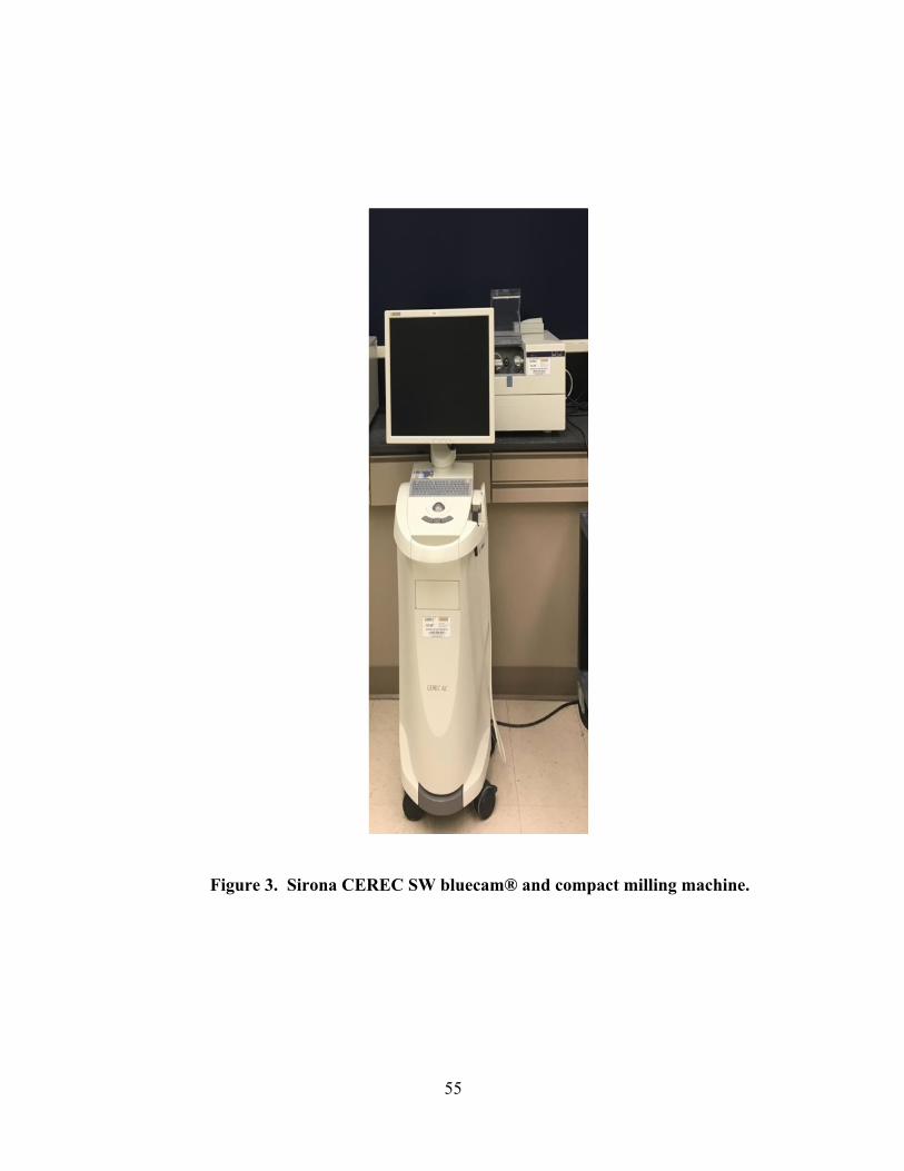
optoelectronically scanned using Sirona CEREC SW BlueCam® (Fig.3) and Software 4.0
edition (Figs. 4,5). A biogeneric copy was applied as a design for the generation of a similar core
for all posts. A virtual model was created and the die was trimmed. Restoration parameter was

33
set at a spacer of ten um for all groups respectively (Fig. 6). The software generated a milling
proposal. An evaluation of the restoration in three dimensions and vertical sections were taken
(Figs. 7,8,9). The figures showed the CEREC software measuring an actual 5.8 and 6mm post
space for 5.5mm post milled. IPS e.max CAD (lithium disilicate glass-ceramic) block was
mounted in the milling unit Sirona CEREC 3® compact milling unit (Fig. 3). Each restoration
was milled in approximately 15 min using the fast-milling set up (Fig. 11). The milling burs, the
cylinder pointed bur and the step bur were changed every 5 cycles to prevent any errors due to
bur wear.
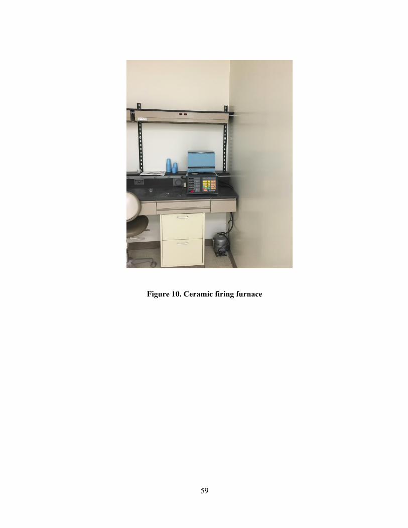
Following the milling procedure the restorations were tempered to reach the fully
crystallized state. In the course of this process, lithium disilicate crystals (Li2Si2O5) are formed
to assure optimum material strength (Fig. 10). Groups A and B were scanned, designed, and
milled for each die 20 times (Figs.12,13,14). The figures show that the 5mm and 10mm post
space measured with the CEREC 4.0® software accurately milled post length of 5mm and 10
mm. Group C die was scanned and milled 20 times. The die for group C was measured up to
13.7. It wasn’t able to mill a post beyond 1mm (Fig15,16).

34
15.0 MEASUREMENT OF PRECISION AND FIT
Each restoration was subjected to a 2 step evaluation to assess the precision of fit. The
marginal gap was measured for each Post & Core to determine the fit to the die, using scanning
electron microscopy (SEM) technology at the University of Pittsburgh Swanson School of
Engineering (Fig. 20). Biological sample condition 10 KV, low vacuum and the backscatter
electron compo mode were used. The low vacuum mode was used to prevent charging of the
sample. A sample holder stage was created based on the pilot study trial designs (Fig. 21b). The
two designs (A and B) were prototyped out of MDF in order to see which was the best way to
hold the two surfaces together on the SEM sample stage (Fig 21a). They consisted of stainless
steel socket head cap screws and stainless steel springs opposing each other in a yoke. It was
determined that a combination of both methods (A and B) worked best, so the MDF prototype
model was copied and machined from aluminum with an added base compatible with the SEM
sample stage (Fig. 21). Each sample holder stage carried three samples, one from each Group A,
B and C, starting from one to twenty (Fig. 22,23).
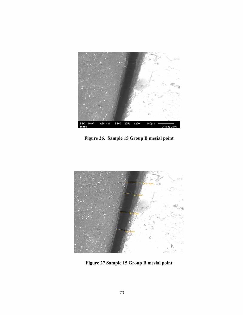
The interface between the ceramic and the acrylic tooth was measured under 200X
magnification. The micrograph was transferred to micrograph analyzing software. The software
has a 100 um installed ruler as an analyzing tool to measure the gap (Fig. 24a). Measurement
was accomplished using the 100 um installed ruler and a line calibration tool which measure the

35
vertical distance between the margin of the ceramic coping and the die (Fig. 24b). Estimations
were done at three points: mesial, buccal and distal for each sample. Three measurement lines
were taken at each point. The total was 180 micrographs and nine assessment lines per each
sample. Example of micrographs showing smallest interface, medium and largest interface
estimated (Fig. 24,25,26)
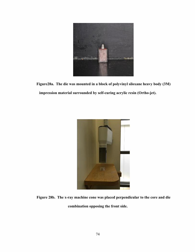
A total number of 60 radiograph were taken for all samples to determine post length. The
machine cone was placed perpendicular to the core and die combination opposing the front side
(Fig. 28b). The die was mounted in a block of polyvinyl siloxane heavy body (3M) impression
material to mimic the periodontal ligament and bone radio-opacity surrounded by self-curing
acrylic resin (Ortho-Jet®) for strength (Fig. 28a). Mipax radiographic software was used to
measure the post length from the core base to the end of the post using the ruler tool (Fig. 29).
Radiographs for sample number 10 for Group A, B and C are presented in Fig. 29. Examples of
the restoration milled for Group A, B and C are demonstrated in Fig. 30. Measurement for each
post length was confirmed by using a mm caliper shown in Fig. 31.
36
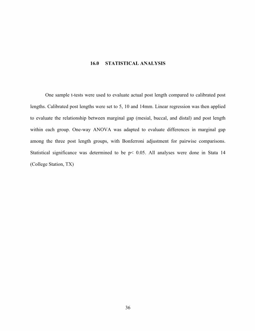
16.0 STATISTICAL ANALYSIS
One sample t-tests were used to evaluate actual post length compared to calibrated post
lengths. Calibrated post lengths were set to 5, 10 and 14mm. Linear regression was then applied
to evaluate the relationship between marginal gap (mesial, buccal, and distal) and post length
within each group. One-way ANOVA was adapted to evaluate differences in marginal gap
among the three post length groups, with Bonferroni adjustment for pairwise comparisons.
Statistical significance was determined to be p< 0.05. All analyses were done in Stata 14
(College Station, TX)

37
17.0 RESULTS
Mean post length for group A, calibrated at 5mm, was 6.3mm. The difference of 1.3 mm
was statistically significant (p<0.01). Mean post length for group B, calibrated at 10mm was
10.0mm. The difference of <1 mm was not statistically significant (p=0.75). Mean post length
for group C, calibrated for 14mm, was 11.0mm. The difference of 3 mm was statistically
significant (p<0.01).
38
Table 3. One sample T Test Group A
Variable
interval
O
bs
M
ean
S
td. Err.
S
td. Dev
[95
% Conf.
Post
length
2
0
6
.3105
.0
844782
.
377798
[6.1
33685
-
6.487315]
Mean=mean(post length) t= 15.5129
Ho: mean = 5 degrees of freedom = 19
Ha: mean < 5 Ha: mean!= 5 Ha: mean > 5
Pr(T < t) = 1.0000 Pr(|T| > |t|) = 0.0000 Pr(T > t) = 0.0000

39
Table 4. One sample T Test Group B
Variable
interval
O
bs
M
ean
S
td. Err.
S
td. Dev
[95
% Conf.
Post
length
2
0
1
0.0295
.0
900394
.4
026684
[9.8
410
45
-
10.21795]
Mean=mean(post length) t= 0.3276
Ho: mean = 10 degrees of freedom = 19
Ha: mean < 10 Ha: mean != 10 Ha: mean > 10
Pr(T < t) = 0.6266 Pr(|T| > |t|) = 0.7468 Pr(T > t) = 0.3734

40
Table 5. One sample T Test Group C
Variable
interval
O
bs
M
ean
St
d. Err.
St
d. Dev
[95
% Conf.
Post
length
2
0
1
1.0475
.0
712183
.3
184978
[10.
89844
-
11.19656]
mean = mean(post length) t = -41.4571
Ho: mean = 14 degrees of freedom= 19
Ha: mean < 14 Ha: mean != 14 Ha: mean > 14
Pr(T < t) = 0.0000 Pr(|T| > |t|) = 0.0000 Pr(T > t)=1.0000

41
Table 6. Histogram Post Length
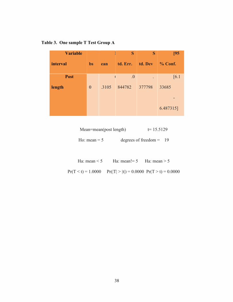
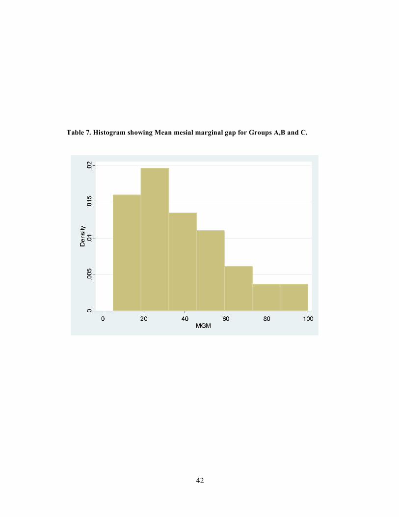
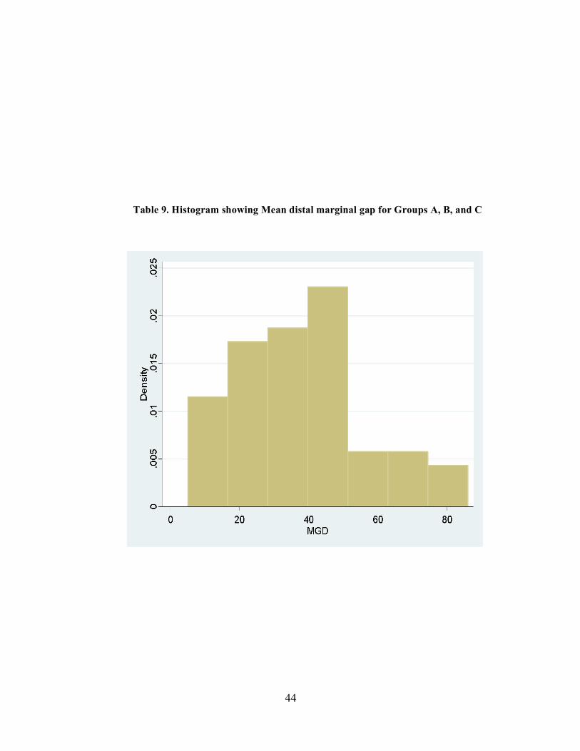
Overall there was no pattern of relationship between marginal gap and post length among
the three groups. ANOVA® showed statistically significant differences in mean mesial marginal
gap among the groups (p<0.01), with the 5mm post length and 10mm group being significantly
different from each other (p<0.01). ANOVA® showed statistically significant differences in
mean buccal marginal gap among the groups (p=0.02), with the 5mm post length group and
10mm group being significantly different from each other (p=0.01). ANOVA® showed no
statistically significant differences in the distal mean marginal gap among the groups (p=0.36).
The mean mesial marginal gap for the three groups was 37.85 um, the mean buccal marginal gap
was 31.73333 um and the mean distal marginal was 38.16667 um.
42
Table 7. Histogram showing Mean mesial marginal gap for Groups A,B and C.
43
Table 8. Histogram showing Mean Buccal marginal gap for groups A, B and C
44
Table 9. Histogram showing Mean distal marginal gap for Groups A, B, and C

45
18.0 DISCUSSION
The objective of this study was to determine the focal point of the CEREC BlueCam®
and evaluate the capability of the machine to mill ceramic Post & Core restorations. Three
master dies were fabricated from a polymer material. The coronal part of the die simulated an
ideal core preparation (2 mm above the CEJ with a 1.5 to 2mm ferrule). Canal space was
prepared to three lengths according to the die group. The canal length of group A was prepared
for a post length of 5mm. Group B canal space was prepared for a post length of 10 mm. Group
C post length was prepared to 14mm. There are few publications addressing Post & Core
restorations. However, a 14mm maximum focal length for the CAD/CAM camera was
established through communication with Sirona USA and Sirona Germany150, 151. There was
only one article in the dental literature concerning this topic151.
After scanning the restoration 20 times for each group, it was determined that a depth of
5mm and 10mm was relatively easy to reach with the CEREC three camera. A 13.7mm depth
was captured by the camera at the 14mm depth. However, the machine wasn’t able to mill any
restoration beyond 11mm. The Mean post length for Group A was 6.3mm, which was longer
than the prepared post length. The difference of 1.3mm was statistically significant (p<0.01).
Mean post length for Group B was 10.0mm, which is the same length of the prepared post space.
46
The difference of <1mm was not statistically significant (p=0.75). The mean post length for
Group C was 11.0mm, which was three mm shorter than the prepared post space. The difference
of 3mm was statistically significant (p<0.01).
In a pilot study, die D was prepared and scanned as in group A,B and C above, with the
post space depth prepared to 15mm. The die was scanned with the camera, and a virtual model
was created. The camera could not read at the 15mm depth. The proposed model was missing the
final working depth point. The software offered a restoration with no post at all Instead it had a
hole similar to the virtual model (Fig. 17). The model was milled, and a core with a hole and
without a post was the product (Fig. 18).
During the pilot study three restoration spacer parameters were tried 0, 10 um, and 20
um. Samples of six restorations were fabricated using the Lava® ultimate Cad/Cam restorative
blocks, three for each die at 5mm and 10mm in depth. It was noted that the post length was 1 mm
shorter after changing the space parameter from twenty to zero um. However, delivery of the
milled Post & Core was less passive. Several adjustments were performed in order to insert the
restoration with a minimum marginal gap. Nakamura et al., determined that the marginal fit of
CEREC crowns were changed when the cement space was altered from 10 um to 30-50 um. The
marginal gap with space setting 30-50um ranged from 53-67 um. Nevertheless, the space setting
of 10 um showed a gap of 95 um158. This study had different findings from Nakamura study.
This could be due to the difference in the restoration type. Nakamura study was carried out on
CEREC crowns. This study of Post & Core restorations was considerably different. It was
determined in this study that the CEREC software considers the post as a part of the internal

47
surface of the restoration. When the space parameter is changed, the software increases the relief
of the inner face of the post. This is the reason why the post length is shortened. The longest
posts were milled at zero space parameters. The posts were engaging the canal and were not
passively seated without significant adjustments. Posts milled at the 20-um setting were 1mm
shorter and passively seated. In conclusion, the 10 um calibration was chosen as the ideal space
setting for Post & Core. This setting balances post length and the passive fit of the restoration. It
was found that minimum adjustments were needed at this setting.
Overall, there was no pattern of relationship between marginal gap and post length
among the three groups. ANOVA® showed statistically significant differences in mean mesial
marginal gap among the groups (p<0.01), with the 5mm post length group and 10mm group
being significantly different from each other (p<0.01). The test also showed statistically
significant differences in mean buccal marginal gap among the groups (p=0.02), with the 5mm
post length group and 10mm group being significantly different from each other (p=0.01).
The results agree with ADA specification No. 8128 which states that the luting cement for
a dental crown should not surmount 40 um when using type II luting agent. Christenson’s study
agreed as well with the ADA specification and our results130. Another Scanning electron
microscopic study by Lofstrom LH et al., on cemented cast gold restorations showed that
margins from 7 to 65 um were acceptable146. Multiple in vitro studies found the mean marginal
gaps ranging from 9 to 82 um which agreed with this investigation139, 140, 141, 142, 143.

48
The present study had limitations using the Sirona CEREC SW BlueCam® and the
Sirona CEREC Three Compact Milling Machine®. Currently the most predominant CEREC
system is its fourth generation product, CEREC AC BlueCam®. It captures images using a
visible blue light emitted from an LED blue diode as its light source. The CEREC AC
BlueCam® can capture one quadrant of the digital impression within 1 minute and the antagonist
in a few seconds. The newest CEREC system, CEREC AC Omnicam®, marketed in 2012 offers
higher qualities. First, BlueCam® imaging is a single-image acquisition technique, while
Omnicam® imaging technology is a continuous imaging mode. With the latter method, serial
data acquisition generates a 3D model. The BlueCam® can be applied to a single tooth or to a
quadrant. The Omnicam® can be used for a single tooth, quadrant or an entire arch. Finally,
BlueCam® must be used with an opaque powder coating of titanium dioxide before scanning to
assure uniform light dispersion and to improve scan efficacy83. Advantages of the Omnicam®
over the BluCam® include powder-free scanning and precise 3D images with natural color.
Powder-free scanning has a superior advantage with a larger scanning area84. It is possible that
introduction of the Optispray® powder to 14mm post length might introduced errors in capturing
the full depth of the prepared canal. Accumulation of the powder at the end of the canal working
length could have been the reason behind the milled post being shorter than the actual canal
length. The virtual model created by the software was able to detect a depth up to 13.7mm, but
the milled post only extended to 11mm. Use of the new Omnicam® technology could resolve
errors introduced by the Optispray® powder.
This study presents a new valid method of fabricating custom made ceramic Post &
Core. A post length up to 11mm was successfully milled which is an adequate depth for a post

49
space. According to Torabinjad 47 about 5mm or more of radiographic gutta percha is necessary
to assure an apical seal 47,48,49. For the anteriors and bicuspid teeth it is recommended that 5mm
of apical gutta-percha be retained, and the post extends to that level. However, for molars the
length is determined by the root thinning or perforation. Posts in molars should be extended
approximately 5 mm in the canal length47,50. While measuring 700 teeth, Shillingburg et al.,
noted that making the post length equal to the clinical crown length would cause the post to
encroach on the 4.0mm “safety zone” of gutta percha in some teeth51. Zillich and Corcoran
presented data comparing length guidelines to average, long and short root lengths and the need
to retain adequate apical seal. When posts were one half of the root length, the endodontic seal
(5 mm) was rarely compromised in average roots. When posts were two-thirds of the root length,
many of the average and short root length teeth had compromised apical seals. When the post
was equal to the crown length, an adequate seal was only possible on teeth with average or long
root lengths. With short-rooted teeth, even the shorter post guideline of being equal to the crown
length produced a compromised apical seal.
High strength ceramic Post & Core systems allow for the fabrication of restorations with
optimal esthetics, good biocompatibility and an excellent periodontal tissue response. In
addition, bonded restorations have higher resistance to vertical root fracture. Bex et al.,17
investigated the effect of dentin-bonded resin post-core preparations on resistance to vertical root
fracture and concluded that dentin-bonded resin post-core restorations provided significantly less
resistance to failure than cemented custom cast Post & Core and that the dentin-bonded resin
Posts & Core fractured in every instance before the roots fractured. Saupe et al.,18 compared the
fracture resistance between custom metal cast Posts & Core and a resin-reinforced dowel system

50
for structurally compromised roots. Their results indicated that resistance to the masticatory load
of a resin-reinforced Post & Core system was greater than that of a morphologic Post & Core
restoration. They also reported that when a bonded resin Post & Core was used on structurally
weakened roots, there was no statistically significant difference in strength between Post & Core
restorations that used a ferrule and those without a ferrule.
Having the Post & Core in a single unit decreases the frequency of failure by creating a
monoblock, which has various advantages over its multiple unit counterparts.
Digital dentistry offers optimum dental service in the same visit, saving both patient and
clinician time and money. Fasbinder et al.,19 has shown that the use of digital impressions is
more efficient than the usual 5-7-minute set times of polyvinyl-siloxane impressions. One recent
study reported that scanning was 10 minutes faster than conventional impressions for single
abutments and short span fixed partial dentures19,20.
Future studies
With the availability of newer CAD/CAM systems the Omnicam® and with
future new generations of the system more research is needed to evaluate the impact of this
recent technology on the Post & Core method proposed in this study. Further evaluation of the
biomechanics of high strength ceramics and zirconia in terms of their shear and fracture strength,
fatigue and cyclic load when used as Post & Core is suggested since dental literature lacks
detailed information in this venue. The resin bond strength between ceramics and dentin, and its
effect on the post tooth combo needs to be evaluated as an altering factor for the fracture
behavior of these posts. Bond strength testing methods are proposed, like macroshear and the

51
macro-tensile bond strength test. Finally, clinical trials and long-term follow-up are
recommended, as these in vitro studies have limitations.

52
19.0 CONCLUSION
This study evaluated the use of CAD/CAM technology as a method to fabricate single-
unit all-ceramic Post & Core restorations by means of a direct optoelectronic scanning
impression of the post space and milling of the ceramic Post & Core restoration. The results of
this study disprove the null hypothesis:
1. Chair side CAD/CAM technology (Sirona CEREC BlueCam®) cannot produce direct single
unit all ceramic Post & Core restorations with an canal depth of 10 mm. Results prove that
chairside CAD/CAM technology (Sirona CEREC BlueCam®) can produce direct single unit all
ceramic Post & Core restoration up to 10mm of canal depth .
2. There was no pattern of relationship between marginal gap and post length among the three
post groups. The Mean marginal gap for the three groups was 38 um. The smallest detected gap
was 5 um and the largest 100 um. The present study marginal gap results according to Holmes
definition are clinically acceptable.
3. Chairside CAD/CAM is a valid method for fabricating a single unit all ceramic Post & Core.
Future studies are needed to evaluate the biomechanical properties of ceramic Post &
Core restorations

53
20.0 FIGURES
Figure 1. Scannable model made from whip mix lean rock stone®

54
Figure 2a and b. Handpiece surveyor was used to idealize the preparation depth.
55
Figure 3. Sirona CEREC SW bluecam® and compact milling machine.

56
Figure 4. Sirona CEREC BlueCam® software
Figure 5. Sirona CEREC BlueCam® software
optoelectronic scanning of post space

57
Figure 6. Restoration parameter was set at 10 um for the spacer for all groups
respectively.

58
Figure 8. 6mm post space measured with CEREC® software 4.0
Figure 9a. Front view pre milling 5mm post
Figure 9b. Side view pre milling 5mm post
59
Figure 10. Ceramic firing furnace

60
i
Figure 11. Compact milling machine fabricating the post
Figure 12. 10mm post space and proposed Post & Core

61
Figure 13. 10mm post space depth measured with 4.0 CEREC® software
Figure 14a. pre-milling proposal for 10mm Post & Core
Figure 14b. Side view pre milling proposal for 10mm Post & Core

62
Figure 15a. Group C post space 14mm proposed and core 11mm
Figure 15b. Group C post space measured with the software 13.7, however the
proposed restoration shown is only 11mm

63
Figure 16a. Group C 11mm post front view pre milling proposal
Fig. 16b. Group C 11mm post side view pre milling proposal

64
Figure 17. Camera wasn’t able to read the end working length point

65
Figure 18a. Software proposing a restoration of the core side view only.
Fig. 18b. Software proposing a restoration of the core front view only.

66
Figure 19a. Milling proposal of the core front view only.
Figure 19b. Milling proposal of the core front view only.

67
Figure 20a. JSM -6610LV® scanning electron microscope
Figure 20b. Marginal gap micrograph process using the software

68
design A design B
Figure 21a. Sample holder stage
Figure 21b. Aluminum mechanical device for holding samples

69
Figure 22. The three groups sample mounted A on the far right and C on the far left

70
Figure 23a. Sample inside SEM chamber
Fig. 23b. Mounted sample inside SEM chamber

71
Figure 24a. Sample 17 Group c mesial point measurement at X200.
Picture showing the 100 um ruler.
Figure 24b. Sample 17 Group C mesial point measurement using the line
measurement tool at three areas.

72
Figure 25a. Sample 19 Group C buccal point measurement
Figure 25b. Sample 19 Group C buccal point measurement, using the line
calibration tool at three areas
73
Figure 26. Sample 15 Group B mesial point
Figure 27 Sample 15 Group B mesial point
74
Figure28a. The die was mounted in a block of polyvinyl siloxane heavy body (3M)
impression material surrounded by self-curing acrylic resin (Ortho-jet).
Figure 28b. The x-ray machine cone was placed perpendicular to the core and die
combination opposing the front side.

75
Figure 29. Mipax® x-ray software
Radiographs for sample number 10 for Group A, B and C
Figure 30. Examples of the restoration milled for Group A, B and C

76
Figure 31. mm caliper

77
BIBLIOGRAPHY
1. Cheung, WA: Review of the Management of Endodontically Treated Teeth. Post, Core and the Final Restoration. J Am Dent Assoc 2005;136:611-9.
2. Spielman, AI (2007). "The birth of the most important 18th century dental text: Pierre Fauchard's Le Chirurgien Dentiste". Journal of Dental Research 86 (10): 922–926.
3. http://www.oxfordreference.com/view/10.1093/oi/authority.20110803100420406
4. Peng Liu,a Xu-Liang Deng, DDS, PhD, and Xin-Zhi Wang, DDS,PhD: Use of a CAD/CAM-fabricated Glass Fiber Post & Core to Restore Fractured Anterior Teeth: A Clinical Report. J Prosthet Dent (2010;103:330-333).
5. Albers, HF: Core Build-Ups and Posts, ADEPT Report 1993;4:25-35,
6. Carossa S, Lombardo S, Pera P, Corsalini M, Rastello ML, Preti PG: Influence of Posts & Cores on Light Transmission Through Different All-ceramic Crowns: Spectrophotometric and Clinical Evaluation. IntJ Prosthodont 2001;14:9-14.
7. Vichi A, Ferrari M, Davidson CL. Influence of Ceramic and Cement Thickness on the Masking of Various Types of Opaque Posts. J Prosthet Dent 2000;83:412-7.
8. Sadek FT, Monticelli F, Goracci C, Tay FR, Cardoso PE, Ferrari M: Bond Strength Performance of Different Resin Composites Used as Core Materials Around Fiber Posts, Dent Mater 2007;23:95-9.
9. Plotino G, Grande NM, Bedini R, Pameijer CH, Somma F. Flexural: Properties of Endodontic Posts and Human Root Dentin, Dent Mater 2007;23:1129-35.
10. Plasmans PJ, Visseren LG, Vrijhoef MM, Kayser AF: In vitro Comparison of Dowel and Core Techniques for Endodontically Treated Molars, J Endod 1986;12:382-7.
11. Nurit Bittner, DDS, Thomas Hill, PhD, and Anthony Randi DDS, University College of Dental Medicine, New York, NY Evaluation of a One-piece Milled Zirconia Post & Core with Different Post & Core Systems: An Vn vitro Study. (J Prosthet Dent 2010;103:369-379).
12. Vano M, Goracci C, Monticelli F, Tognini F, Gabriele M, Tay FR, et al., The Adhesion Between Fibre Posts and Composite Resin Cores: The Evaluation of Microtensile Bond Strength Following Various Surface Chemical Treatments to Posts, Int Endod J2006;39:31-9.

78
13. Balkenhol M, Wostmann B, Rein C, Ferger P: Survival Time of Cast Post & Cores: a 10-year Retrospective Study, J Dent 2007;35:50-8.
14. Ferrari M, Cagidiaco MC, Goracci C, Vichi A, Mason PN, Radovic I, et al., Long-term Retrospective Study of the Clinical Performance of Fiber Posts, Am J Dent 2007;20:287-91. 15. Assif D, Gorfil C: Biomechanical Considerations in Restoring Endodontically Treated Teeth, J Prosthet Dent 1994;71:565-7.
16. Fraga RC, Chaves BT, Mello GS, Siqueira JF Jr: Fracture Resistance of Endodontically Treated Roots After Restoration, J Oral Rehabil 1998;25:809-13
17. Bex RT, Parker MW, Judkins JT, Pelleu GB Jr: Effect of Dentinal Bonded Resin Post-Core Preparations on Resistance to Vertical Root Fracture, J 1992;67:768-72.
18. Saupe WA, Gluskin AH, Radke RA Jr: A Comparative Study of Fracture Resistance Between Morphologic Dowel and Cores and a Resin-reinforced Dowel System in the Intraradicular Restoration of Structurally Compromised Roots, Quintessence Int 1996;27:483-91.
19. Computerized Technology for Restorative Dentistry DENNIS J. FASBINDER, DDS American Journal of Dentistry, Vol. 26, No. 3, June, 2013.
20. Patzelt SBM, Lamprinos C, Strub JR, Att W: The Efficacy of Different Intraoral Scanners, J Dent Res 2013;92(Sp Is A): Abstr 464.
21. Ellingsen LA, Fasbinder DJ. In vitro Evaluation of CAD/CAM Ceramic Crowns. J Dent Res 2002;81(Sp Is A):Abstr 2640.
22. Seelbach P, Brueckel C, Wostmann B: Accuracy of Digital and Conventional Impression Techniques and Workflow, Clin Oral Investig 2012; doi:10.1007/s00784-012-0864-4.
23. Chairside CAD/CAM: An Overview of Restorative Material Options Dennis J. Fasblnder, DDS COMPENDIUM January 2012 ,volume 33 number 1.
24. Givan DA, Burgess JO, O’Neal SJ, Aponte AA: Prospective Evaluation of Ceramic Crowns by Digital and Conventional Impressions, J Dent Res 2011;90(Sp Is A): Abstr 380.
25. Harper RH, Lund MR: Treatment of the Pulpless Tooth During Post & Core Construction. Oper Dent 1976;155-60.
26. MondclliJ, Piccino AC, Berbert A: An Acrylic Resin Pattern for a Cast Dowel and Core. J Prosthet Dent 1971;25:413-417.
27. Pickard HM: Variants of the Post Crown. Br Dent,J 1964;117 517-526.
28. Blaukopf ER: Direct acq-lic Davis crown tcchnic. J Am Dent Assoc 1W;3 1:1270-1271.

79
29. Sheets CE: Ihwel and Core Foundations. J Prosthct Dent 197O;23:58-65.
30.Goldrich N Construction of Posts for Teeth with Existing Restorations. J Prosthet Dent 1070;23:173-176.
31.Rosen H: Operative Procedures on Mutilated Endodontically Treated Teeth. J Prosthet Dent 1961;11:973-986 .
32. Rosenberg PA, Antonoff SJ: Goldposts. Common Problems in Preparation and Technique for Fabrication. W State Dent J I971;37:601-606 .
33. Silverstein NH: Reinforcement of Weakened Pulpless Teeth. J Prosthet Dent 1964;14:372-381.
34. Dooley BS: Preparation and Construction of Post Retention Crowns for Anterior Teeth. Aust Dent J 1967;12:543-550 .
35. Baraban DJ: The Restoration of Pulpless Teeth. Dent Clin North Am 1967;633-653.
36. Jacoby WE: Practical Technique for the Fabrication of a Direct Pattern for a Post Core Restoration. J Prosthet Dent I976;35: 357-360 . 37. Dewhirst RB, Fisher DW, Schillingburg HT: Dowel Core Fabrication. J S Cal Dent Assoc 1969;37:444-449.
38. Hamilton Al: Porcelain Dowel Crowns.J Prosthet Dent 1959;9: 639-644. 39. Larato DC: Single Unit Cast Post Crown for Pulpless Anterior Tooth Roots. J Prosth Dent 1966;16:145-149.
40. Christy JM, Pipko DJ: Fabrication of a Dual Post Veneer Crown. J Am Dent Assoc 196i;75:I4 19-1425. 41. Bartlett SO: Construction of Detached Core Crowns for Pulpless Teeth in Only Two Sittings. J h i Dent Assw 1968;77:843- 845. 42. Burnell SC: Improved Cast Dowel and Basic for Restoring Endodontically Treated Teeth. J Am Dent Assoc 1964;68:39-45. 43. Perel ML, Muroff FI: Clinical Criteria for Posts & Cores.J Prosthet Dent 1972;28:405411. 44. Stern N, Hirschfeld Z: Principles of Preparing Endodontically Treated Teeth for Dowel and Core Restorations. J Prosthet Dent 1973:30:162-165.

80
45. Hirschfeld Z, Stern N: Post & Core-The Biomechanical Aspect. Aust Dent J 1972;17:467-468. 46. Henry PJ: Photoelastic Analysis of Post & Core Restorations. Aust D e n t J 1977;22:155-159. 47. Mahmoud T, Richard E, Ashraf F: Endodontics Principle and Practice. 5th edition 48. Fan B, Wu MK, Wessenlink Pr: Coronal Leakage Along Apical Root Fillings After Immediate and Delayed Post Space Preparation, endo Dent Traumatol 15:124,1999. 49. Goodacre CJ, Spolnik KJ: The Prosthodontic Management of Endodontically Treated Teeth: A Literature Review Part II, Maintaining the Apical Seal, J prosthodont 4:51,1995. 50. Abou-Rass M, Jann JM, Jobe D, et al: Preparation of Space for Posting: Effect of Thicknesss of Canal Walls and Incidence of Perforation in Molars. J Am Dent Assoc 104:834.1982. 51. Shillingburg HT, Kessler JC, Wilson EL: Root Dimensions and Dowel Size. Cal Dent Assoc J 1982;10:43-49. 52. Raiden G, Costa L, Koss S, et al: Residual Thickness of Root in First Maxillary Premolars with Post Space Preparation. Jendod 25:502.1999. 53. Johnson JK, Schwartz NL, Blackwell RT: Evaluation and Restoration of Endodontically Treated Posterior Teeth. J Am Dent Assoc 1976;93:597-605. 54. Libman WJ, Nichollas JI: Load Fatigue of Teeth Restored with Cast Post & Core and Complete Crowns. Int J prosthodont 8:155.1995. 55. Tan PL, Aquilino SA, Gratton DG, et al: In vitro Fracture Resistance of Endodontically Treated Central Incisors with Varying Ferrule Heights and Configurations. J Prosth Dent 93:331,2005. 56. Ng CC, Dumbrigue HB, Al-Bayat MI, et al: Influence of Remaining Coronal Tooth Structure Location on the Fracture Resistance of Restored Endodontically Treated Anterior Teeth, J prosthet Dent 95:290.2006. 57. Al-Omiri MK, Mahmoud AA, Rayyan MR, Abu-Hammad O: Fracture Resistance of Teeth Restored with Post-retained Restorations: an Overview. J Endod 2010;36:1439-49. 58. Akkayan B, Gulmez T: Resistance to Fracture of Endodontically Treated Teeth Restored with Different Post Systems. J Prosthet Dent 2002;87:431-7. 59. Al-Omiri MK, Rayyan MR, Abu-Hammad O: Stress Analysis of Endodontically Treated Teeth Restored with Post-retained Crowns: a Finite Element Analysis study. J Am Dent Assoc. 2011;142:289-300.

81
60. Cagidiaco MC, Radovic I, Simonetti M, et al: Clinical Performance of Fiber Post Restorations in Endodontically Treated Teeth: 2 Year Results. Int J Prosthodont 2007;20:293-298. 61. Zillich RM, Corcoran JF: Average Maximum Post Lengths in Endodontically Treated Teeth. J Prosthet Dent 1984;52:489-491. 62. Beuer F, Schweiger J, Edelhoff D: Digital Dentistry: An Overview of Recent Developments for CAD/CAM Generated Restorations. Br Dent J 2008;204(9):505-511. 63. Fasbinder DJ, D.D.S and Neiva GF, D.D.S: Computerized Restorative Dentistry, The journal of the Michigan dental association April 2012 . 64. Beuer, Schweiger J, and Edelhoff, D: Digital Dentistry: An Overview of Recent Developments for CAD/CAM Generated Restorations. F. British Dental journal volume 204 No 9 may 10 2008. 65. Correia ARM, Sampaio Fernandes JCA, Cardoso JAP, et al: CAD/CAM: Informatics Applied to Fixed Prosthodontics. Rev Odontol UNESP 2006;35:183-189. 66. Intraoral Digital Impression Technique: A Review. Su Ting-shu, DDS & Sun Jian, DDS, PhD Journal of Prosthodontics 24 (2015) 313–321, 2014 by the American College of Prosthodontists. 67. May KB, Russell MM, Razzoog ME, Lang BR: Precision of Fit: The Procera All-ceramic Crown. J Prosthet Dent 1998; 80: 394-404. 68, Reich S, Wichmann M, Nkenke E, Proeschel P. Clinical fit of All-ceramic Three-unit Fixed Partial Dentures, Generated with Three Different CAD/CAM Systems. Eur J Oral Sci 2005; 113: 174-179. 69. Mormann, WH: The Evolution of the CEREC System. J Am Dent Assoc 2006;137:7s-13s. 70. Birnbaum NS, Aaronson HB: Dental Impressions Using 3D Scanners: Virtual Becomes Reality. Compend Contin Educ Dent 2008;29:494-505.
71-.Kachalia PR, Geissberger MJ. Dentistry a la carte: In-office CAD/CAM Technology. J Calif Dent Assoc 2010;38:323-330.
72. Garg AK: Cadent iTero’s Digital System for Dental Impressions: The End of Trays and Putty? Dent Implantol Update 2008;19:1-4.
73. Fasbinder DJ. Using Digital Technology to Enhance Dentistry. Compend Contin Educ Dent 2012;23:2-9.

82
74. Mehl A, Gloger W, Kunzelmann K H, Hickel R: A New Optical 3-D Device for the Detection of Wear. J Dent Res 1997; 76: 1799-1807. 75. May KB, Russell MM, Razzoog ME, Lang BR: Precision of Fit: the Procera AllCeram Crown.J Prosthet Dent 1998; 80: 394-404. 76. Webber B, McDonald A, Knowles J: An In vitro Study of the Compressive Load at Fracture of Procera AllCeram Crowns with Varying Thickness of Veneer Porcelain. J Prosthet Dent 2003; 89: 154-160.
77. May KB, Russell MM, Razzoog ME, Lang BR. Precision of fit: the Procera AllCeram Crown. J Prosthet Dent 1998; 80: 394-404. 78. Webber B, McDonald A, Knowles J. An In vitro Study of the Compressive Load at Fracture of Procera AllCeram Crowns with Varying Thickness of Veneer Porcelain. J Prosthet Dent 2003; 89: 154-160. 79. Mehl A, Gloger W, Kunzelmann K H, Hickel R: A New Optical 3-D Device for the Detection of Wear. J Dent Res 1997; 76: 1799-1807. 80. Abduo J, Lyons K, Bennamoun M: Trends in Computer-aided Manufacturing in Prosthodontics: A Review of the Available Streams. Int J Dent, 2014 (2014), p. 783948 81. Rekov ED: Dental CAD/CAM Systems: A 20-year Success Story. J Am Dent Assoc. 2006;137(Suppl):5S-6S. 82. CEREC 3: Operating Instructions for the Acquisition Unit. Sirona The Dental Company, Bensheim, Germany, 2004. 83. Poticny DJ, Klim J: CAD/CAM In-office Technology: Innovations After 25 Years for Predictable, Esthetic Outcomes. J Am Dent Assoc 2010;141:5S-9S. 84. Birnbaum NS, Aaronson HB, Stevens C, et al: 3D Digital Scanners: A High-Tech Approach to More Accurate Dental Impressions. Inside Dent 2009;5:70-74. 85. Galhano GA, Pellizzer EP, Mazaro JV: Optical Impression Systems for CAD-CAM Restorations. J Craniofac Surg 2012;23:e575-e579. 86. Birnbaum NS, Aaronson HB, Stevens C, et al: 3D digital Scanners: A High-Tech Approach to More Accurate Dental Impressions. Inside Dent 2009;5:70-74. 87. Intraoral Digital Impression Technique: A Review. Su Ting-shu, DDS & Sun Jian, DDS, PhD Journal of Prosthodontics 24 (2015) 313–321, 2014 by the American College of Prosthodontists.
83
88. Tariq F. Alghazzawi BDS, MS, MS MTE, PhD, Review Advancements in CAD/CAM Technology: Options for Practical Implementation. Journal of Prosthodontic Research 60 (2016) 72–84. 89. Rusin RP: Properties and Applications of a New Composite Block for CAD/CAM. Compend Contin Educ Dent. 2001:22(6 suppl):35-41. 90. Paradigm MZlOO Block: Technical Product Profile. St. Paul, MN: 3M ESPE; 2000. 91. Vita Machinable Polymers: Product Information. Bad Säckingen, Germany: Vita Zahnfabrik; 2010. 92. Telio CS and Telio-CAD: Instructions for Use. Amherst, NY: Ivoclar Vivadent Technical: December 2009. 93. The Dental company Sirona CEREC-THE MOST IMPORTANT CLINICALS STUDIES 2014. 94. Kelly R, Machinable Ceramics. In Mörmann WH (ed.) State of the Art of CAD/CAM Restorations, 20 Years of CEREC, Berlin: Quintessence, 2006: 29–38 Krejci I, Wear of CEREC and Other Restorative Materials. In Mörmann WH (ed.) International Symposium on Computer Restorations, Berlin: Quintessence, 1991: 245–251 Al-Hiiyasat AS, Saunders WP, The Abrasive Effect of Glazed, Unglazed, and Polished Porcelain on the Wear of Human Enamel, and the Influence of Carbonated Soft Drinks on the Rate of Wear. Int J Prosthodont 1997; 10: 269–282. 95. Mormann WH, Bindl A: All-ceramic, Chair-side Aided Design/computer Aided Machining Restorations. Dent Clin North Am 2002;46:405–26. 96. Otto T, de Nisco S. Computer-aided Direct Restorations: a 10-year Prospective Clinical Study of CEREC CAD/CAM Inlays and Onlays. Int J Prosthodont 2002;15:122–8. 97. Christensen RP, Galan AD, Mosher TA. Clinical Status of Eleven CAD/CAM Materials After One to Twelve Years of Service. In: Mormann WH, editor. State of the art of CAD/ CAM restorations: 20 years of CEREC. Surrey: Quintessence Publishing; 2006. 98. Vitablocs Mark II for CEREC. Materials Science and Clinical Studies. Brea, CA: Vident; September2003. 99. Liu PR, Essig ME: Panorama of Dental CAD/CAM Restorative Systems. Compend Contin Educ Dent 2008;29:482–8. 100. Bindl A, Luthy H, Moormann WH: Fracture Load of CAD/ CAM-generated Slot-inlay FPDs. Int J Prosthodont 2003;16:653–60. 101. Giordano R: Materials for Chairside CAD/CAM-produced Restorations. J Am Dent Assoc. 2006;137(Suppl.):14S–21S.

84
102. Keshvad A, Hooshmand T, Asefzadeh F, Khalilinejad F, Alihemmati M, Van Noort R: Marginal Gap, Internal Fit, and Fracture Load of Leucite-reinforced Ceramic Inlays Fabricated by CEREC InLab and Hot-pressed Techniques. J Prosthodont 2011;20:535–40 103. Guess PC, Strub JR, Steinhart N, Wolkewitz M, Stappert CF. All-ceramic Partial Coverage Restorations – Midterm Tesults of a 5-year Prospective Clinical Splitmouth study. J Dent 2009;37:627–37. 104. Giordano R, McLaren EA: Ceramics Overview: Classification by Microstructure and Processing Methods. Compend Contin Educ Dent 2010;31:682–8. 105. Raymond Wai Kim Li BDS, MFGDP(UK), MGDSRCS(Ed.), FRACDS, FCDSHK, FHKAM*, Tak Wah Chow MSc, PhD, FDSRCSEd. FADM,Jukka Pekka Matinlinna BSc, CSc, MSc, PhD, MRSC, MADM, MIADR Review Ceramic dental biomaterials and CAD/CAM technology: State of the art . journal of prosthodontic research 58 (2014) 208–216. 106. Della Bona A. Bonding to Ceramics: Scientific Evidence for Clinical Dentistry. Sao Paolo: Editoria Artes Medica; 2009. 107. Ho GW, Matinlinna JP: Insights on Porcelain as a Dental Material. Part II: Chemical Surface Treatments. Silicon 2011;3:117–23. 108. Tysowsky, GW: The Science Behind Lithium Disilicate: a Metal-free Alternative. Dent Today. 2009;28(3):93-97.
109. Hill TJ, McCabe P, Tysowsky G: Bonding and Thickness Effect on Fracture Load of CAD/CAM Crowns [abstract]. J Dent Res. 2OO8;87(spec iss A). Abstract 2321.
110. Bindl A, Lüthy H. Mörmann WH. Thin-wall Ceramic CAD/CAM Crown Copings: Strength and Fracture Pattern. J Oral Rehabil. 2OO6;33(7):52O-528.
111. Culp L, McLaren EA: Lithium Disilicate: The Restorative Material of Multiple Options. Compend Contin Educ Dent 2010;31:716–25.
112. Asai T, Kazama R, Fukushima M, Okiji T: Effect of Overglazed and Polished Surface Finishes on the Compressive Fracture Strength of Machinable Ceramic Materials. Dent Mater J 2010;29:661–7.
113. Guess PC, Zavanelli RA, Silva NR, Bonfante EA, Coelho PG, Thompson VP: Monolithic CAD/CAM Lithium Disilicate Versus Veneered Y-TZP Crowns: Comparison of Failure Modes and Reliability After Fatigue. Int J Prosthodont 2010;23:434–42.
114. Tysowsky GW: The Science Behind Lithium Disilicate: a Metal-free Alternative. Dent Today 2009;28:112–3.

85
115. Reich S, Fischer S, Sobotta B, Klapper HU, Gozdowski S: A Preliminary Study on the Short-term Efficacy of Chairside Computer-aided Design/Computer-assisted Manufacturing-generated Posterior Lithium Disilicate Crowns. Int J Prosthodont 2010;23:214–6.
116. Fasbinder DJ, Dennison JB, Heys D, Neiva G: A clinical Evaluation of Chairside Lithium Disilicate CAD/CAM Crowns: a Two-year Report. J Am Dent Assoc 2010;141(Suppl. 2):10S–4S.
117. Schultheis S, Strub JR, Gerds TA, Guess, PC: Monolithic and Veneered CAD/CAM Lithium Disilicate Bridges Vs. Metal-ceramic: Comparison of the Fracture Load Values and Failure Modes upon Fatigue. IPS e.max /scientific report/vol.02/2001-2013PS
118 . Bindl A, Mormann WH: Survival Rate of Mono-ceramic and Ceramic-core CAD/CAM-generated Anterior Crowns over 2–5 years. Eur J Oral Sci 2004;112:197–204.
119. Bindl A, Mormann WH. An Up to 5-year Clinical Evaluation of Posterior In-Ceram CAD/CAM Core Crowns. Int J Prosthodont 2002;15:451–6.
120. Apholt W, Bindl A, Luthy H, Mormann WH: Flexural Strength of CEREC 2 Machined and Jointed InCeram- alumina and InCeram–zirconia bars. Dent Mater 2001;17:260–7.
121. Chong KH, Chai J, Takahashi Y, Wozniak W: Flexural Strength of In-Ceram-alumina and In-Ceram- zirconia Core Materials. Int J Prosthodont 2002;15:183–8.
122. Heffernan MJ, Aquilino SA, Diaz-Arnold AM, Haselton DR, Stanford CM, Vargas MA: Relative Translucency of Six All-ceramic Systems. Part II: Core and Veneer Materials. J Prosthet Dent 2002;88:10–5.
123. Kelly JR, Benetti P: Ceramic Materials in Dentistry: Historical Evolution and Current Practice. Aust Dent J 2011;56(Suppl. 1):84–96.
124. Miyazaki T, Nakamura T, Matsumura H, Ban S, Kobayashi T: Current Status of Zirconia Restoration. J Prosthodont Res 2013;57:236–61.
125. Giordano R, McLaren EA: Ceramics Overview: Classification by Microstructure and Processing Methods. Compend Contin Educ Dent 2010;31:682–8.
126. Li J, Liao H, Hermansson L: Sintering of Partially-stabilized Zirconia and Partially-stabilized zirconia-hydroxyapatite Composites by Hot Isostatic Pressing and Pressureless Sintering. Biomaterials 1996;17:1787–90.
127. Holmes JR, Bayne SC, Holland GA, Sulik WD: Considerations in Measurement of Marginal Fit. J Prosthet Dent. 1989;62: 405–408.
86
128. American Dental Association: ANSI/ADA Specification No. 8 for Zinc Phosphate Cement. In: Guide to Dental Materials and Devices (ed 5). Chicago, American Dental Association, 1970-1971.
129. Holden JE, Goldstein G, Hittelman EL, et al: Comparison of the Marginal Fit of Pressable Ceramic to Metal Ceramic restorations. J Prosthodont 2009;18:645-648.
130. Christensen G: Clinical and Research Advancements in Cast-gold Restorations. J Prosthet Dent 1971;25:62-68.
131. Fransson B, Oilo G, Gjeitanger R: The Fit of Metal-ceramic Crowns, a Clinical Study. Dent Mater 1985;1:197-199. 132. McLean JW, von Fraunhofer JA: The Estimation of Cement Film Thickness by an In vivo Technique. Br Dent J 1971;131: 107-111.
133. Kohorst P, Brinkmann H, Li J, et al: Marginal Accuracy of Four-unit Zirconia Fixed Dental Prostheses Fabricated Using Different Computer-aided Design/computer-aided Manufacturing Systems. Eur J Oral Sci 2009;117:319-325.
134. Pera P, Gilodi S, Bassi F, et al: In vitro Marginal Adaptation of Alumina Porcelain Ceramic crowns. J Prosthet Dent 1994;72:585-590.
135. Sulaiman F, Chai J, Jameson L, Wozniak W: A Comparison of the Marginal Fit of In-ceram, IPS Empress, and Procera crowns. Int J Prosthodont 1997; 10: 478–484.
136. McLean JW, von Fraunhofer JA. The Estimation of Cement Film Thickness by an In vivo Technique. Br Dent J 1971; 131: 107–111.
137. Gulker I. Margins. NY State Dent J 1985; 51: 213–217.
138. Moldovan O, Rudolph H, Quaas S, Bornemann G, Luthardt RG. Internal and External Fit of CAM-made Zirconia Bridge Frameworks – a Pilot Study. Dtsch Zahna ̈rztl Z 2006; 61: 38–42.
139. Bindl A, Mörmann WH: Fit of All-ceramic Posterior Fixed Partial Denture Frameworks In vitro. Int J Periodontics Restorative Dent 2007; 27: 567–575.
140. Beuer F, Aggstaller H, Edelhoff D, Gernet W, Sorensen J: Marginal and Internal fits of Fixed Dental Prostheses Zirconia Retainers. Dent Mater 2009; 25: 94–102.
141. Beuer F, Naumann M, Gernet W, Sorensen JA: Precision of Fit: Zirconia Three-unit Fixed Dental Prostheses. Clin Oral Investig 2008; doi: 10.1007/s00784-008-0224-6 [e-pub ahead of print.
142. Gonzalo E, Suarez MJ, Serrano B, Lozano JF: Marginal Fit of Zirconia Posterior Fixed Partial Dentures. Int J Prosthodont 2008; 21: 398–399.

87
143. Coli P, Karlsson S: Precision of a CAD/CAM Technique for the Production of Zirconium Dioxide Copings. Int J Prosthodont 2004; 17: 577–580.
144. Reich S, Wichmann M, Nkenke E, Proeschel P: Clinical Fit of All-ceramic Three-unit Fixed Partial Dentures, Gerated with Three Different CAD/CAM Systems. Eur J Oral Sci 2005; 113: 174–179.
145. Wettstein F, Sailer I, Roos M, Hämmerle CHF. Clinical Study of the Internal Gaps of Zirconia and Metal Frameworks for Fixed Partial Dentures. Eur J Oral Sci 2008; 116: 272–279.
146. Lofstrom LH, Barakat MM: Scanning Electron Microscopic Evaluation of Clinically Cemented Cast Gold Restorations. J Prosthet Dent. 1989;61:664–669.
147. Noor A. Nawafleh, BS, MDentTech,1,3 Florian Mack, Dr. Med. Dent, PD,1Jane Evans, DipDT, BFET, PhD,1 John Mackay, RDP,1 & Muhanad M. Hatamleh, BSc, MPil, MSc(Health Mgmt), Dip(Maxfac(Prosthetics), PhD2,3 : Accuracy and Reliability of Methods to Measure Marginal Adaptation of Crowns and FDPs: A Literature Review Journal of Prosthodontics 22 (2013) 419–428 ⃝c 2012 by the American College of Prosthodontists.
148. Schmalz G, Federlin M, Reich E: Effect of Dimension of Luting Space and Luting Composite on Marginal Adaptation of a Class II Ceramic Inlay. Int J Prosthodont 1995;11:333-339.
149. Groten M, Girthofer S, Probster L: Marginal Fit Consistency of Copy-milled All-ceramic Crowns During Fabrication by Light and Scanning Electron Microscopic Analysis In vitro. J Oral Rehabil 1997;24:871-881.
150. Personal communication through emails with Dr. Richard fox Sirona clinical advisor, USA and Mr Adam Busch CEREC product manager Sirona USA.
151. Joachim Pfeiffer und Axel Schwotzer, Dreidimensionale optische Vermessung von Zahnen.
152. Lava ultimate CAD/CAM restorative technical product profile by the manufacturer.
153. Christensen GJ: In-office CAD/CAM Milling of Restorations. The Future? J Amer Dent Assoc 2008.
154. Poticny DJ, Klim J: CAD/CAM In-office Technology. J Amer Dent Assoc 2010; 141: 5S-9S.
155. US Nanotechnology Initiative. <http://www.nano.gov/>.
156. Magne P, Paranhos MP, Burnett LH Jr, Magne M, Belser UC: Fatigue Resistance and Failure Mode of Novel-design Anterior Single-tooth Implant Restorations: Influence of Material

88
Selection for Type III Veneers Bonded to Zirconia Abutments. Clin Oral Impl Res. 2011 Feb; 22 (2): 195-200. 157 (University of Southern California).
157. DeLong R, Douglas WH: Development of an Artificial Oral Environment for the Testing of Dental Restoratives: Bi-axial Force and Movement Control. J Dent Res. 1983 Jan; 62 (1): 32-6.ka.
158. Nakamura T, Dei,Kojima T, Wakabayashi K: Marginal and Internal Fit of CEREC 3 CAD/CAM All- ceramic Crowns. The international journal of prosthodontics 2003;16:244-8.
159. Yeo IS, Yang JH, Lee JB: In vitro Marginal Fit of Three All-ceramic Crown Systems. J Prosthet Dent 2003;90:459-464.
160. Suarez MJ, Villaumbrosia PG, Pradies G, et al: Comparison of the Marginal Fit of Procera Allceram Crowns with Two Finish Lines. Int J Prosthodont 2003;16:229-232.
161. Leong D, Chai J, Lautenschlager E, et al: Marginal Fit of Machine-milled Titanium and Cast Titanium Single Crowns. Int J Prosthodont 1994;7:440-74.
162. Albert FE, El-Mowafy OM: Marginal Adaptation and Microleakage of Procera Allceram Crowns with Four Cements. Int J Prosthodont 2004;17:529-535.
163. White SN, Yu Z, Tom JF, et al: In vivo Marginal Adaptation of Cast Crowns Luted with Different Cements. J Prosthet Dent 1995;74:25-32.
164. Yeo IS, Yang JH, Lee JB: In vitro Marginal Fit of Three all-ceramic Crown Systems. J Prosthet Dent 2003;90:459-464.
165. Petteno D, Schierano G, Bassi F, et al: Comparison of Marginal Fit of Three Different Metal-ceramic Systems: an In vitro Study. Int J Prosthodont 2000;13:405-408.
166. Campbell SD, Sirakian A, Pelletier LB, et al: Effects of Firing Cycle and Surface Finishing on Distortion of Metal Ceramic Castings. J Prosthet Dent 1995;74:476-481.
167. Gassino G, Barone MS, Scanu M, et al: Marginal Adaptation of Fixed Prosthodontics: A New In vitro 360-degree External Examination Procedure. Int J Prosthodont 2004;17:218-223.
168. Leong D, Chai J, Lautenschlager E, et al: Marginal Fit of Machine-milled Titanium and Cast Titanium Single Crowns. Int J Prosthodont 1994;7:440-747.
169. Groten M, Axmann D, Pro ̈bster L, et al: Determination of the Minimum Number of Marginal Gap Measurements Required for Practical In vitro Testing. J Prosthet Dent 2000;83:40-49.
170. Gonzalo E, Suarez MJ, Serrano B, et al: A Comparison of the Marginal Vertical Discrepancies of Zirconium and Metal Ceramic Posterior Fixed Dental Prostheses Before and After Cementation. J Prosthet Dent 2009;102:378-384.

89
171. Lee KB, Park CW, Kim KH, et al: Marginal and Internal Fit of All-ceramic Crowns Fabricated With Two Different CAD/CAM Systems. Dent Mater J 2008;27:422-426.