event to analog signal encoder - psg instrumentation
TRANSCRIPT
For additional Information Contact: Philip Starbuck(909)841-7156 [email protected]
Copyright © 2009 Philip Starbuck
Event to Analog Signal Encoder
Description
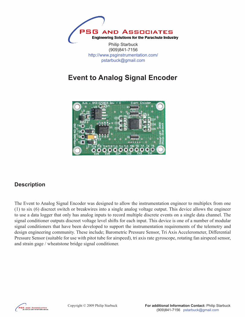
The Event to Analog Signal Encoder was designed to allow the instrumentation engineer to multiplex from one (1) to six (6) discreet switch or breakwires into a single analog voltage output. This device allows the engineer to use a data logger that only has analog inputs to record multiple discrete events on a single data channel. The signal conditioner outputs discreet voltage level shifts for each input. This device is one of a number of modular signal conditioners that have been developed to support the instrumentation requirements of the telemetry and design engineering community. These include; Barometric Pressure Sensor, Tri Axis Accelerometer, Differential Pressure Sensor (suitable for use with pitot tube for airspeed), tri axis rate gyroscope, rotating fan airspeed sensor, and strain gage / wheatstone bridge signal conditioner.
Philip Starbuck(909)841-7156
http://www.psginstrumentation.com/[email protected]
For additional Information Contact: Philip Starbuck(909)841-7156 [email protected]
Copyright © 2009 Philip Starbuck
FEATURES:Power Supply Voltage: +5.3 to +26VDC, Note device rated for 60VDC maximum.•From one (1) to six (6) discreet events.•Internal pullups on all inputs (10K to +5V).•Internal ESD protection on all inputs.•May be used with normally open, normally closed switches or breakwires.•On board radio frequency interference (RFI) attenuation tom minimize the effects of external RFI •interference.Remote power enable: pull enable terminal to ground to turn device off, leave open or apply >= 2V to •enable device (Note: Pin has 10K Pullup Resistor to (+) Power In).Unipolar output: 0 to +5.0V signal output range.•Integral100HzfourpoleButterworthantiailisingfilter(cornerfrequencymaybespecifiedbyuserattime•of order).Typical output load: >= 10K ohms•Operating Ambient Temp. Range: -40°C to +85°C•Storage Temperature: -65°C to +150°C•
Analog Signal Weighting:
TheencodingcircuitusedisabasicR-2Rresistorladdernetwork.Switch1MSB(mostsignificantbit)toSwitch6LSB(leastsignificantbit)aredrivenfromdigitallogicgates.Thebitsareswitchedbetween0 volts (digital 0) and 5V (digital 1). The R-2R network causes the digital bits to be weighted in their contribution to the output voltage Vout. In this circuit up to may be used, giving 64 possible discrete output levels. Depending on which switches are closed or open the output voltage (Vout) will be a stepped value between 0 volts and 4.921875 V full scale. A Excel spreadsheet is available to decode the analog voltage recorded into the discrete switch condition (open or closed) vs. time (sample history) during the post test processing of the data.
For a digital value VAL, of a R-2R DAC of 6 bits of 0 V/5V, the output voltage V is: V = 5V× VAL / 2
In the example shown, N = 6 and hence 2 = 64. Vout will vary between 000000, VAL = 0 (V = 0V) and 111111, VAL = 63 (V . = 4.921875 V).
Minimum (single step) VAL = 1, we haveV = 5 × 1 / 64 = 0.078125 volts
Maximum output (111111) VAL = 63, we haveV = 5 × 63 / 2 = 5 x 63/64 = 4.921875 volts
6out
out
Nout
out
out
out6
For additional Information Contact: Philip Starbuck(909)841-7156 [email protected]
Copyright © 2009 Philip Starbuck
CONNECTIONS:
To Data Logger:T1 - (+) BatteryT2 – Ground (Signal/Power Return)T3 – Power DisableT4 – Analog Output (data logger/telemetry)
To Switches / Breakwires:T5 – Switch 1T6 – Switch CommonT7 – Switch 2T8 – Switch CommonT9 – Switch 3T10 – Switch CommonT11 – Switch 4T12 – Switch CommonT13 – Switch 5T14 – Switch CommonT15 – Switch 6T16 – Switch Common
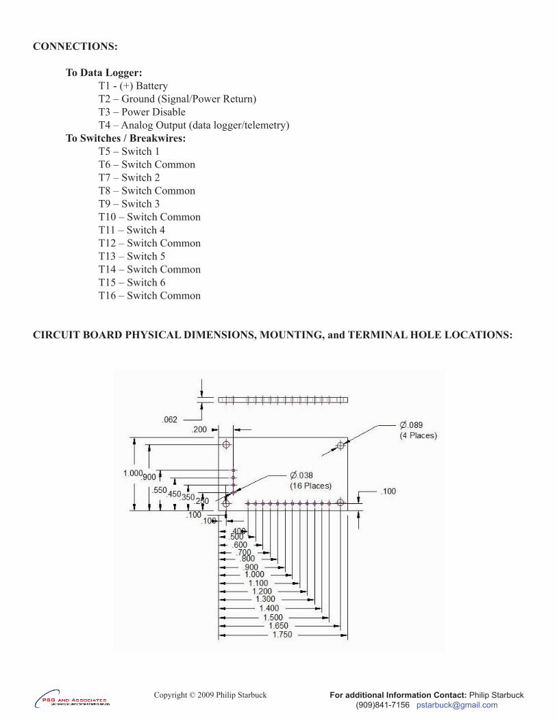
CIRCUIT BOARD PHYSICAL DIMENSIONS, MOUNTING, and TERMINAL HOLE LOCATIONS: