evp series proportional control valves - clippard … data sheets/evp...clippard is pleased to add...
TRANSCRIPT
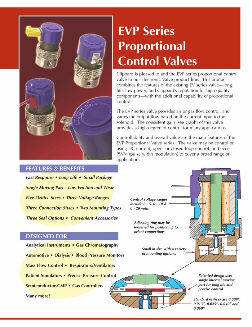
Clippard is pleased to add the EVP series proportional controlvalve to our Electronic Valve product line. This productcombines the features of the existing EV series valve—longlife, low power, and Clippard’s reputation for high qualitycomponents—with the additional capability of proportionalcontrol.
The EVP series valve provides air or gas flow control, andvaries the output flow based on the current input to thesolenoid. The consistent gain (see graph) of this valveprovides a high degree of control for many applications.
Controllability and overall value are the main features of theEVP Proportional Valve series. The valve may be controlledusing DC current, open- or closed-loop control, and evenPWM (pulse width modulation) to cover a broad range ofapplications.
EVP SeriesProportionalControl Valves
Control voltage rangesinclude 0 - 5, 0 - 10 & 0 - 20 volts.
Adjusting ring may beloosened for positioning toorient connections
Patented design usessingle internal movingpart for long life andprecise control
Small in size with a variety of mounting options.
Standard orifices are 0.009”,0.013”, 0.025”, 0.040” and0.060”
FEATURES & BENEFITS Fast Response • Long Life • Small Package
Single Moving Part—Low Friction and Wear
Five Orifice Sizes • Three Voltage Ranges
Three Connection Styles • Two Mounting Types
Three Seal Options • Convenient Accessories
DESIGNED FORAnalytical Instruments • Gas Chromatography
Automotive • Dialysis • Blood Pressure Monitors
Mass Flow Control • Respirators/Ventilators
Patient Simulators • Precise Pressure Control
Semiconductor-CMP • Gas Controllers
Many more!
1.388 (35.3)
Valve Type: 2-Way, ProportionalMedium: Air, GasesTemperature Range: 32° to 120°F
(0° to 50°C)Power Consumption: 1.9 watts at 23°C
2.3 watts max.Mounting: In-line or ManifoldPorts: #10-32 Female (In-line)
#10-32 Male Stud (Manifold)Seal Material: Buna-N Standard; Viton®,
EPDM and others availableMaximum Hysteresis: 10% of full current
54 Ohmg Coil0.025 Orifice100 psig23˚C
Specifications
Dimensions
1.560(39.6)
IN
OU
T
#6-32 thd. - 7/32 deepmounting holes
#10-32 thd.outlet
#10-32 thd.inlet
.250(6.4)
.500(12.7)
.875 (22.2)
1.187 (30.1)
Standard & Manifold Mount Models Coil Styles
EC 0.025” Pin Connector EV 18” Wire Leads, 26 Gauge
ET 0.110” x 0.020” Space Connector
0 .02 .04 .06 .08 .10 .12 .14 .16 .18 .20Input Current (amps)
25
20
15
10
5
0
Flow
(lite
rs/m
inut
es)
Typical Performance
54 ohms Coil0.025 Orifice
100 psig23°C
All dimensions are stated in inches (millimeters)
Flow at Orifice Rated Maximum
Diameter Pressure Current (±10%)
Inches psig slpm scfh0.009 100 2.7 5.70.013 100 6.7 14.20.025 100 23.5 50.0 0.040 50 19.0 40.00.060 25 14.0 30.0
1.388 (35.3)
1.560(39.6)
.158 (4.0)
#10-32 thd.inlet
.218(5.5)
outlet
.875 (22.2)
1.187 (30.1)
Nominal Voltage Input Current Coil Resistance Max. VoltageRange at 23°C Range at 23°C Required
0 - 5 vdc 0 - 0.370 amps 13.5 ohms 6.2 vdc0 - 10 vdc 0 - 0.185 amps 54 ohms 12.4 vdc0 - 20 vdc 0 - 0.092 amps 218 ohms 24.8 vdc
1/8" NPT(external)
#10-32outlet port(internal)
0.437 (11.1)
0.375 (9.5)
0.875(22.2)
#10-32inlet port
0.250(6.4)
.500(12.7)
0.437 (11.1)
.875(22.2)
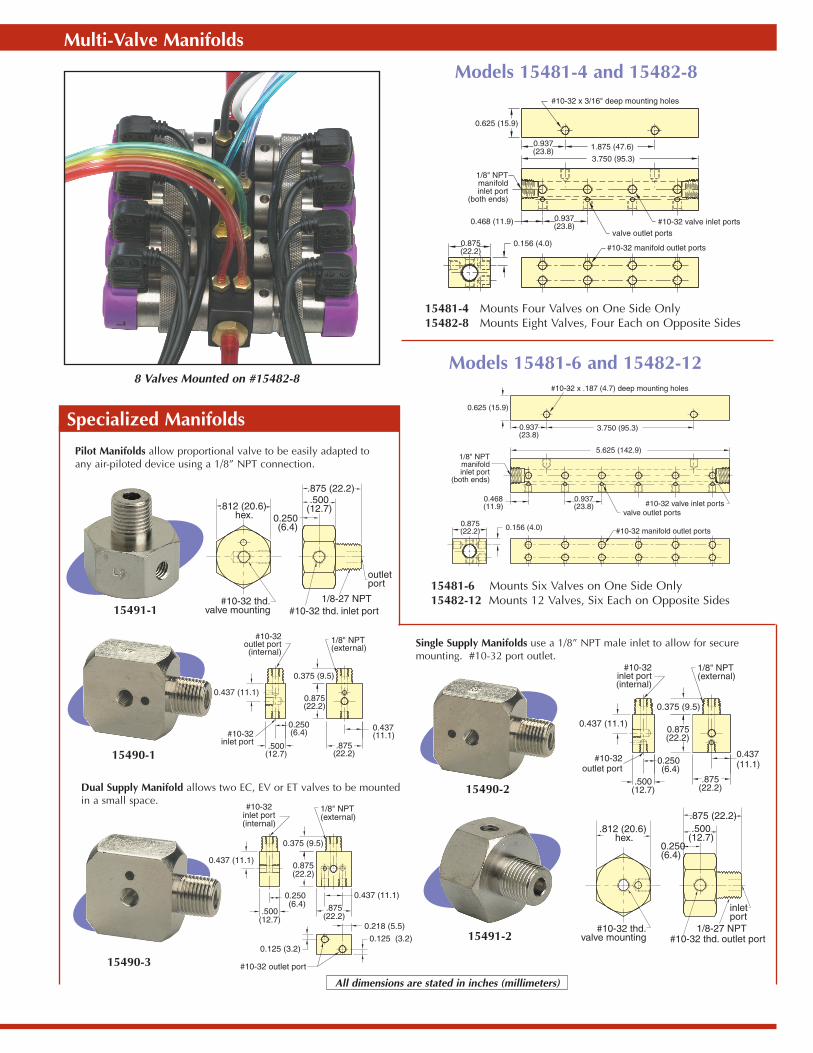
Pilot Manifolds allow proportional valve to be easily adapted toany air-piloted device using a 1/8” NPT connection.
Single Supply Manifolds use a 1/8” NPT male inlet to allow for securemounting. #10-32 port outlet.
Dual Supply Manifold allows two EC, EV or ET valves to be mountedin a small space.
15491-1
15491-2
Models 15481-4 and 15482-8
Models 15481-6 and 15482-12#10-32 x .187 (4.7) deep mounting holes
0.625 (15.9)
0.937(23.8)
3.750 (95.3)
1/8" NPTmanifoldinlet port
(both ends)
5.625 (142.9)
0.468(11.9)
0.937(23.8)
valve outlet ports#10-32 valve inlet ports
#10-32 manifold outlet ports0.875(22.2) 0.156 (4.0)
15481-4 Mounts Four Valves on One Side Only15482-8 Mounts Eight Valves, Four Each on Opposite Sides
15481-6 Mounts Six Valves on One Side Only15482-12 Mounts 12 Valves, Six Each on Opposite Sides
8 Valves Mounted on #15482-8
1/8" NPT(external)
#10-32inlet port(internal)
0.437 (11.1)
0.375 (9.5)
0.875(22.2)
#10-32outlet port
0.250(6.4)
.500(12.7)
0.437(11.1)
.875(22.2)
1/8" NPT(external)
#10-32inlet port(internal)
0.437 (11.1)
0.375 (9.5)
0.875(22.2)
0.250(6.4)
.500(12.7)
#10-32 outlet port
0.125 (3.2)
0.218 (5.5)
0.125 (3.2)
0.437 (11.1)
.875(22.2)
.812 (20.6) hex.
.875 (22.2).500
(12.7)0.250(6.4)
outletport
1/8-27 NPT#10-32 thd. inlet port
#10-32 thd.valve mounting
.875 (22.2).500
(12.7)0.250(6.4)
inletport
1/8-27 NPT#10-32 thd. outlet port
#10-32 thd.valve mounting
.812 (20.6) hex.
Multi-Valve Manifolds
15490-1
15490-3
15490-2
0.156 (4.0)
0.468 (11.9)
1/8" NPTmanifoldinlet port
(both ends)
0.937(23.8)
#10-32 manifold outlet ports
valve outlet ports#10-32 valve inlet ports
3.750 (95.3)
1.875 (47.6)0.937(23.8)
0.625 (15.9)
#10-32 x 3/16" deep mounting holes
0.875(22.2)
Specialized Manifolds
All dimensions are stated in inches (millimeters)
E - P - - -
Clippard Instrument Laboratory, Inc.7390 Colerain Avenue • Cincinnati, Ohio 45239-5396
Phone 513-521-4261 • Fax 513-521-4464www.clippard.com
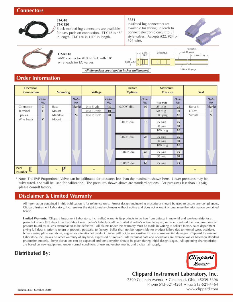
ET-C48ET-C120Black molded lug connectors are availablefor easy push on connection. ET-C48 is 48”in length, ET-C120 is 120” in length.
3831Insulated lug connectors areavailable for wiring up leads toconnect electronic circuit to ETstyle valves. Accepts #22, #24 or#26 wire.
C2-RB18AMP connector #103959-1 with 18”wire leads for EC valves.
Bulletin 3.03, October, 2003
0.093(2.4)
0.187 (4.7)
0.625 (15.9)
18 (457.2)
0.437 (11.1)
red, 26 gauge
black, 26 gauge
Connectors
All information contained in this publication is for reference only. Proper design engineering procedures should be used to assure any compliances.Clippard Instrument Laboratory, Inc. reserves the right to make changes without notice and does not warrant or guarantee the information containedherein.
Limited Warranty. Clippard Instrument Laboratory, Inc. (seller) warrants its products to be free from defects in material and workmanship for aperiod of ninety (90) days from the date of sale. Seller’s liability shall be limited at seller’s option to repair, replace or refund the purchase price ofproduct found by seller’s examination to be defective. All claims under this warranty must be made in writing to seller’s factory sales departmentgiving full details, prior to return of product, postpaid, to factory. Seller shall not be responsible for product failure due to normal wear, accident,buyer’s misapplication, abuse, neglect or alteration of product. Seller will not be responsible for any consequential damages. Clippard InstrumentLaboratory, Inc. makes no other warranty of any kind, expressed or implied. All technical data and operations are average values based on standardproduction models. Some deviations can be expected and consideration should be given during initial design stages. All operating characteristicsare based on new equipment, under normal conditions of use and environments, and a clean air supply.
Distributed By:
Disclaimer & Limited Warranty
PartNumber
* Note: The EVP Proportional Valve can be calibrated for pressures less than the maximum shown here. Lower pressures may be substituted, and will be used for calibration. The pressures shown above are standard options. For pressures less than 10 psig, please consult factory.
Order Information
Electrical Orifice MaximumConnection Mounting Voltage Options Pressure Seal
Order Order Order Order Order OrderNo. No. No. No. *see note No. No.
Connector C Base (blank) 0 to 5 vdc 05 0.009” dia. 09 25 psig 25 Buna-N (blank)Terminal T Mount 0 to 10 vdc 10 50 psig 50 EPDM ESpades Manifold M 0 to 20 vdc 20 100 psig A0 Viton® VWire Leads V Mount
0.013” dia. 13 25 psig 2550 psig 50100 psig A0
0.025” dia. 25 25 psig 2550 psig 50100 psig A0
0.040” dia. 40 25 psig 2550 psig 50
0.060” dia. 60 25 psig 25
All dimensions are stated in inches (millimeters)