experimental investigation of wellhead twin- screw pump ... · point, screw-pump performance had...
TRANSCRIPT
PB Oil and Gas Facilities • April 2014 April 2014 • Oil and Gas Facilities 73
SummaryOnshore gas developments are often characterized by drilling, frac-turing, and production of wells before low-pressure gas-gathering systems are in place. As well production declines, liquid-loading is-sues begin to appear. Gas-well deliquefication (GWD) can be ac-complished with compression or in-well artificial-lift methods or both. Wellhead wet-gas compression is desirable in that it does not require well intervention to provide GWD, and it is especially useful in maintaining well production in the interim period before field-wide compression is available. Even when fieldwide compression is available, local wellhead compression is desirable at various lo-cations in a field as high-rate wells are added or for wells located at peripheral locations. The use of a twin-screw pump to provide boost for high-gas-volume-fraction (GVF) multiphase flow was in-vestigated experimentally. Tests were conducted with pressure rises ranging up to 250 psi for GVFs greater than 90%. Water and air were used as the working fluids. The pumping system is a commer-cially available 230-gal/min twin-screw pump (60 hp) with a design speed of 3,600 rev/min used in conjunction with a knock-out tank that recirculates liquid from the pump exit to provide seal flush. The amount of electrical power required to operate the pump, the inlet liquid- and gas-flow rates, the pressure rise, and the inlet and exit temperatures were recorded. From these data, the volumetric effi-ciency (flow rate), pump effectiveness, and mechanical efficiency were calculated. Because there is a fixed clearance between the ro-tating screws and the pump housing, there is a leakage from the high- to low-pressure regions of the pump that will reduce the volu-metric efficiency of the pump. It was found that the volumetric ef-ficiency decreased significantly with decreasing pump speed and increasing GVF. At full speed, the volumetric efficiency was be-tween 70 and 88% at ΔP=50 psi. Increasing ΔP to 250 psi decreased these values to 55 and 81%, respectively. The mechanical efficiency was relatively constant over the pressure-rise range, varying from a high of 48% at the lowest inlet pressure (10 psig) at 0% GVF to a low of 14% for both inlet pressures (10 and 50 psig) at 100% GVF. Overall, the testing demonstrated the ability of a surface twin-screw pump to provide wet-gas compression.
IntroductionThe use of twin-screw pumps to accomplish GWD and enhance production of wet-gas wells has been under investigation for many years. Compression not only solves liquid-loading prob-lems, but also boosts production rates and increases the ultimate recovery. The ability to boost a wet-gas stream provides a number
of advantages when compared with conventional single-phase gas compression.
1. Wet-gas compression boosts pressure to transport gas to market without the need to separate the phases, eliminating additional required equipment.
2. Uninterrupted flow, even under severe slugging conditions.3. Simplicity, to lower operational expenditure (OPEX): easier
to install, operate, and move, and reduces the downtime asso-ciated with a single-phase compressor with separation equip-ment.
4. Small footprint for large volume.5. Lower capital expenditure without the need for separation
equipment.6. More flexibility to adapt to the well-condition change by
means of a variable-frequency-drive (VFD) system.7. Maintain a constant suction pressure by means of a VFD unit.
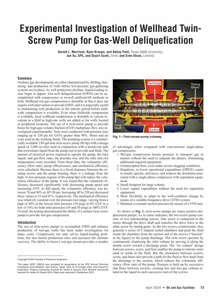
As shown in Fig. 1, twin-screw pumps are rotary positive-dis-placement pumps. As its name indicates, the two-screw pump con-sists of two intermeshing screws. One screw is connected to the motor through the drive shaft and transfers the drive force to the other screw by timing gears. As the two screws counterrotate, they generate a series of C-shaped sealed chambers and push the fluid inside the chambers from the suction end of the screws (“Suction” in the figure) to the pump discharge. The twin screw operates by continuously displacing the inlet volume by moving it along the double screw toward a discharge point. The “no contact” design between screws, screw, and liner enables the pump to tolerate some sand or solids in the fluid. But the clearances between screws, screw, and liners also provide a path for the fluid to flow back from the discharge to the suction, which reduces the volumetric effi-ciency (flow rate) of the pump. Pressure is built up by successive slip flows between cavities, creating less and less gas volume re-lated to the liquid in each successive turn of the screws.
Experimental Investigation of Wellhead Twin-Screw Pump for Gas-Well Deliquefication
Gerald L. Morrison, Ryan Kroupa, and Abhay Patil, Texas A&M University;
Jun Xu, SPE, and Stuart Scott, Shell; and Sven Olson, Leistritz
Copyright © 2014 Society of Petroleum Engineers
This paper (SPE 159910) was accepted for presentation at the SPE Annual Technical Conference and Exhibition, San Antonio, Texas, USA, 8–10 October 2012, and revised for publication. Original manuscript received for review 8 January 2013. Revised manuscript received for review 22 August 2013. Paper peer approved 3 September 2013.
Fig. 1—Twin-screw-pump cutaway.
Discharge
Suction
DriveShaft
TimingGears
74 Oil and Gas Facilities • April 2014 April 2014 • Oil and Gas Facilities 75
BackgroundVetter and Wincek (1993) and Vetter et al. (2000) modeled how twin-screw pumps work under multiphase conditions. Until this point, screw-pump performance had been well-documented for single-phase flow, but the complicated nature of multiphase flow required some simplifying assumptions. An important assump-tion made by Vetter and Wincek (1993) was that the pump could be modeled as a series of fluid-filled cylinders moving toward the center of the pump. The model was composed of a set of rotating disks that made up the chambers in which the volumes of disks im-itated the sealed chambers. The slip itself could then be modeled like a piston, compressing the gas as the chamber moved along while the liquid in the mixture acted like the chamber sealant. For GVF of up to 96%, the compression can be assumed isothermal. According to the analysis of Vetter and Wincek (1993), the circum-ferential gap between the screw and the stator was responsible for approximately 80% of the total leakage flow. The assumption of phase separation based on the centrifugal acceleration caused by the rotation of the disks allowed the analysis of multiphase fluid to be broken down into single-phase liquid flow at the outer clear-ance between the screw and the casing. This assumption was later tested by Vetter and coworkers in a laboratory and was shown to be valid for GVF up to 85% (Vetter and Wincek 1993; Vetter et al. 2000).
The experiments conducted to validate the model showed some interesting results. For the first time, the pressure distribution across the screws was investigated. For single-phase flow, the axial pres-sure distribution linearly increases as the fluid travels from the suc-tion to the pump exit. For GVF > 0, the pressure profile is no longer linear. This means that unlike single-phase flow, in which each of the cavities contributes equally to the pressure increase, multiphase flow at high GVF has a nonlinear pressure rise. The pressure in-crease is localized in the screw chamber closest to the pump exit.
The consequence of the fluid mixture leaking between the screws and the casing from the high-pressure region to the pump inlet results in a decrease in the flow rate of the pump, as both the pressure rise across the pump and the GVF of the mixture in-crease. Chan (2006) proposed that by increasing the viscosity of the liquid phase, the volumetric efficiency could be improved. The fundamental idea is that the viscosity of the liquid phase is the dominant variable in the leakage flow that causes slip. Therefore, it has been predicted that increasing the liquid viscosity will in-crease volumetric efficiency. The increase of viscosity in the liquid fluid was obtained with guar gel. Chan’s (2006) experimental re-sults showed that at high GVFs, the viscosity of the fluid was not an important parameter for pump performance. The increase in vis-cosity did not increase the total flow rate of the pump. This finding was not shown by the previous models of twin-screw pumps oper-ating at high GVFs.
Räbiger (2009) developed a fluid-dynamics and thermody-namics model to simulate the operation of twin-screw pumps oper-ating at high GVFs. The fluid-dynamics model was accomplished by use of computational-fluid-dynamics (CFD) software, and the end result was aimed primarily at the pump designer. Very intricate solid-design models constructed in a computer-aided design pro-gram set the geometry of the screws and gave results very close to those of the actual-pump performance. While the model and pre-diction of performance will not be applicable to the current inves-tigation, it is worth mentioning that the results given by the model showed that it is possible to simulate the pump performance with multiphase fluid. Along with the CFD model, a heat-transfer and thermodynamics pump model was developed as well.
Study ObjectivesThe response of a small (230 gal/min) Leistritz twin-screw pump incorporated into a skid designed to allow the pump to operate even when the GVF is 100% is evaluated in this study. The purposes of the evaluation are as follows:
1. Evaluate the pump performance, especially at high-GVF con-ditions, by examining the flow-rate (Q vs. ΔP) curves and ef-ficiency (η vs.ΔP) curves.
2. Check the integrity of the design and construction. 3. Obtain operational experience with the complete system.
Compression-Process CharacterizationThe performance of multiphase pumps with a gas phase present
is different from a pump operating with an incompressible fluid or incompressible fluid mixture. This change varies with the type of pump being used. Positive-displacement pumps (twin screw, piston, progressing cavity) can usually handle the gas/liquid mixture, pro-vided that there is sufficient liquid to lubricate and seal the pump mechanism. In twin-screw pumps, where there is a finite clearance between the screws and the housing, backflow leakage can become appreciable at high GVF because the liquid provides better sealing than gas.
There are several ways to characterize the performance of mul-tiphase pumps. One is to simply use the incompressible-flow pump equations. In this case, the hydraulic power imparted to the pumped multiphase mixture is given by
Phydraulic=(Qliquid+Qgas)(pout−pin) .....................................................(1)
Here, Qliquid and Qgas represent the volumetric flow rates of the liquid and gas components at the pump inlet, respectively; pout is the pump exit pressure; and pin is the pump inlet pressure. This equation is valid for an ideal incompressible adiabatic process. Hence, the value is incorrect for any case that has gas present. It is a theoretical best-case performance of the pump, which is present when the flow is incompressible.
The compression process of a multiphase flow with gas present can vary depending on the characteristics of the multiphase flow and the pump. For low GVF, the amount of liquid present is suffi-cient to the point that the temperature of the multiphase fluid does not rise significantly. This is because of the high heat capacitance of the liquid absorbing the heat generated by the compression of the gas. As the GVF increases in value, the temperature of the mixture will begin to increase.
The power imparted to the mixture by the pump for isothermal flow is given by
Pisothermal=Qliquid(pout−pin)+Qgaspin1npoutpin
........................................(2)
The first term on the right-hand side of Eq. 2 is the hydraulic power for only the liquid flow. The second term is the power for the
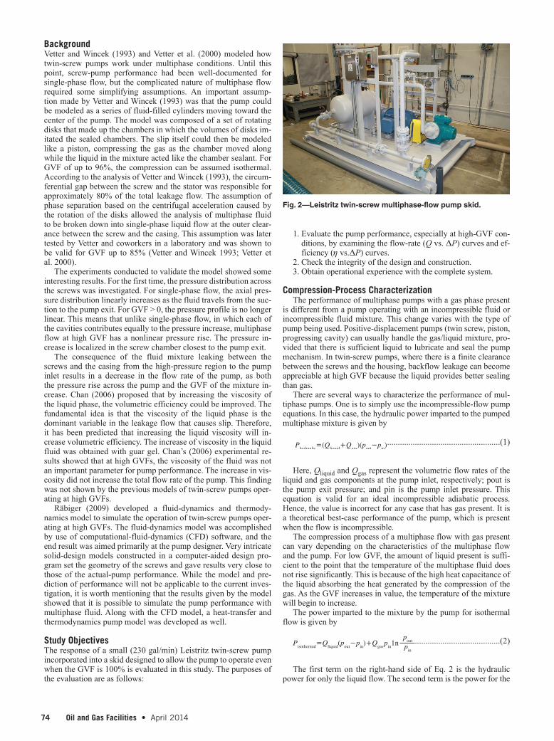
Fig. 2—Leistritz twin-screw multiphase-flow pump skid.
74 Oil and Gas Facilities • April 2014 April 2014 • Oil and Gas Facilities 75
isothermal compression of the gas flow. The ideal-gas law is used in the derivation of this equation and in the equations for polytropic processes discussed later. Therefore, pressure and temperature terms must be expressed in absolute values.
As the GVF of the mixture increases, the liquid no longer has enough thermal capacitance to maintain the mixture at constant tem-perature. This process can be represented as a polytropic process. The polytropic process represents the compression process that is somewhere between isothermal (n=1) and isentropic (n=k=Cp/Cv). The temperature of the mixture increases as it passes through the pump, with the highest temperature rise occurring for an isen-tropic process. The ideal adiabatic reversible-compression process for gases is the isentropic process and is the upper performance limit for high-GVF cases.
Ppolytropic=Qliquid(pout−pin)+nn−1
nn−1pout
pin+Qgaspin −1( )[ ] ..................(3)
There are several ways to measure the performance of a multi-phase pump. One is to compare the decreasing ability of the pump to compress liquid as the amount of gas present increases. A ratio of the power imparted to the multiphase fluid to the power im-parted to a liquid flow based on the same inlet pressure, pressure rise, and inlet volumetric flow rate is termed the pump effective-ness. This represents the degradation of the pump’s ability to impart power to the multiphase fluid compared with liquid-only flow and
is dependent upon only the actual thermodynamic process, not the pump design.
Pump Effectiveness=ηeffective=PmultiphasePhydraulic
.........................................(4)
where Pmultiphase=Pisothermal or Ppolytropic.The basic definition of efficiency is outcome divided by the cost
of the outcome. This can vary for a specific device, depending on whether the temperature rise is useful or must be eliminated. The elimination or rejection of this thermal energy (requiring a heat-transfer process) reduces the useful energy added to the fluid and increases the installation costs by adding additional equipment to change the fluid temperature. The actual application will determine if this thermal energy is useful or must be eliminated. A pump must be experimentally investigated to determine the mechanical- and thermal-energy values imparted to the fluid for the particular pump under specific conditions because friction and leakage will also be present. Two additional metrics are needed to quantify these addi-tional effects. One is the mechanical efficiency of the pump, which is defined as the power added to the fluid divided by the power re-quired to operate the pump:
ηmechanical=PmultiphasePdrive
........................................................................(5)
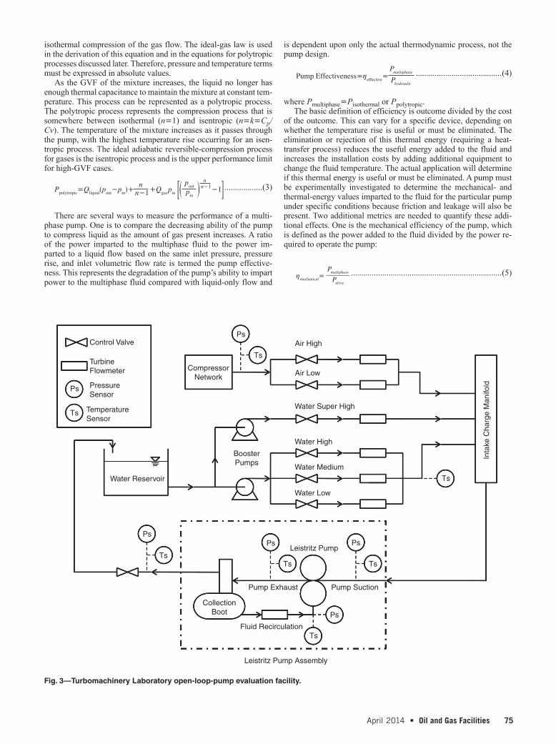
Fig. 3—Turbomachinery Laboratory open-loop-pump evaluation facility.
Control Valve
Turbine Flowmeter
Pressure Sensor
PsAir High
Inta
ke C
harg
e M
anifo
ld
Air Low
Water Super High
Water High
BoosterPumps
CompressorNetwork
Water Reservoir
CollectionBoot
Leistritz Pump Assembly
Leistritz Pump
Fluid Recirculation
Pump Exhaust Pump Suction
Water Medium
Water Low
Ps
TsTs Ts
Ts
Ts
Ts
Ps Ps
Ps
Ps
Ts Temperature Sensor
76 Oil and Gas Facilities • April 2014 April 2014 • Oil and Gas Facilities 77
This value will vary depending on whether the thermal energy is desired or not.
The final measure of a pump’s performance is its volumetric ef-ficiency. This is simply the ratio of the actual volumetric flow rate to the theoretical volumetric flow rate on the basis of the geometry and operating speed of the pump. The decrease in volumetric flow rate from design specifications can be a result of compressibility ef-fects and increased internal leakage (caused by gas leaking more freely than liquid), as is present in twin-screw pumps because of the fixed clearance between the screws and the pump housing. This is solely dependent on the specific pump design. However, it is a very important parameter because it specifies how much the volumetric-flow-rate capacity of a pump is affected by the presence of multi-phase flow.
Experimental FacilityA Leistritz pump assembly designed specifically for high-GVF operation is shown in Fig. 2. The assembly includes a liquid-re-circulation loop through which liquid is separated from the pump discharge, stored in a liquid knockout tank, and is recirculated to the
pump suction through the seal-flush system. This allows the pump to operate at 100% GVF while supplying fluid to the seal flush, helping to internally seal the twin-screw pump. The GVF can be cal-culated on the basis of the fluid mixture passing through the pump, which includes the seal flush, or on the basis of the GVF of the fluid stream entering the skid. For this study, the GVF is calculated at the pump-skid inlet.
The pump was installed in one of the pump loops at the Tur-bomachinery Laboratory of Texas A&M University. The pump loop used is an open system in which charge pumps and air compressors supply the water and air to the pump assembly, respectively. Fig. 3 shows a diagram of the facility. This pump loop has two air-tur-bine flowmeters and four water-turbine flowmeters. The appropriate flowmeter is used to match the required flow rates. Electropneu-matic valves are used to control the air/water mixture and pres-sure at the pump inlet. Another valve is used to set the pressure rise through the pump. A LabVIEW (design software developed by Na-tional Instruments®) program was written to control the flow loop and acquire the data. All data used in this paper represent the overall pump-skid performance. Flow rates, pressures, temperatures, and
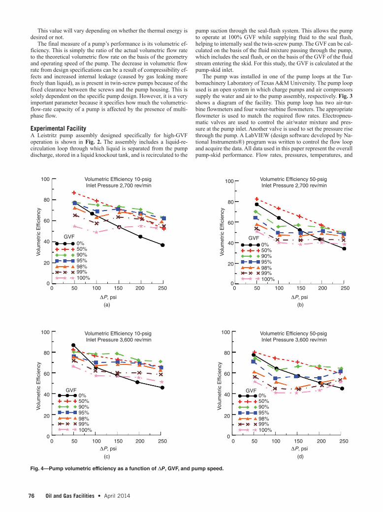
Fig. 4—Pump volumetric efficiency as a function of ΔP, GVF, and pump speed.
100 Volumetric Efficiency 10-psig Inlet Pressure 2,700 rev/min
Vol
umet
ric E
ffici
ency
Vol
umet
ric E
ffici
ency
Vol
umet
ric E
ffici
ency
Vol
umet
ric E
ffici
ency
GVF0%50%90%95%98%99%100%
GVF0%50%90%95%98%99%100%
GVF0%50%90%95%98%99%100%
GVF0%50%90%95%98%99%100%
Volumetric Efficiency 10-psig Inlet Pressure 3,600 rev/min
∆P, psi(a)
(c)
(b)
(d)
∆P, psi
∆P, psi ∆P, psi
Volumetric Efficiency 50-psig Inlet Pressure 2,700 rev/min
Volumetric Efficiency 50-psig Inlet Pressure 3,600 rev/min
80
60
40
20
00 50 100 150 200 250
0 50 100 150 200 250
0 50 100 150 200 250
0 50 100 150 200 250
100
80
60
40
20
0
100
80
60
40
20
0
100
80
60
40
20
0

76 Oil and Gas Facilities • April 2014 April 2014 • Oil and Gas Facilities 77
similar data are all measured at the skid inlet and outlet. GVF is based on the skid-inlet conditions. The fluid recirculated within the skid is not used in any of the performance calculations. The test ma-trix operated the pump at 2,700 and 3,600 rev/min with 0, 50, 90, 95, 98, 99, and 100% GVF for inlet pressures of 10 and 50 psi and pump-pressure rises of 50, 100, 150, 200, and 250 psi.
ResultsThe volumetric efficiency of the twin-screw pump was evaluated at operating speeds of 2,700 (three-quarters speed) and 3,600 rev/min for inlet pressures of 10 and 50 psi. These low inlet pressures were selected because the pump was being considered for use in older gas wells in which liquid loading has become a problem. Higher inlet pressures will produce different results. The volumetric flow rate of the liquid and gas mixture entering the pump skid was measured for these two inlet pressures and pump speeds for pressure rise across the pump varying from 50 to 250 psi. The results are presented as volumetric efficiency, which is the actual skid-inlet volumetric flow rate divided by the design volumetric flow rate of 230 gal/min at 3,600 rev/min and 172 gal/min at 2,700 rev/min. Fig. 4a illustrates how the volumetric flow rate decreases with increasing pump differ-
ential pressure for GVFs varying from 0 to 100% for an inlet pres-sure of 10 psi and a pump speed of 2,700 rev/min. The liquid-only (0% GVF) case follows a typical trend for a twin-screw pump, with the volumetric efficiency decreasing from 78% for a pressure rise of 50 psi to a low of 38% for a pressure rise of 250 psi. The flow rate decreases almost linearly with increasing pressure rise as a re-sult of the higher pressure rise causing more internal leakage. When gas is added, the results are quite different. For a 50-psi pressure rise, increasing the GVF to 50% increases the volumetric efficiency from 78% for pure liquid to 84% for 50% GVF. The flow rate then decreases with increasing GVF, reaching a minimum of 55% for 100% GVF. As the pressure rise increases, the 50%-GVF-condition response is similar to the liquid-only case with near-linear decrease and increasing pressure rise. At the higher GVFs, the flow rate ini-tially decreases as the pressure rise increases from 50 to 100 psi, in-creases for the 150-psi pressure rise, and then slowly decreases from a 150- to 250-psi pressure rise. Once the pressure rise reaches 150 psi, the volumetric efficiency for all the gas cases is larger than for the liquid-only case. It is hypothesized that as the pressure rise in-creases, the pressure drop is sufficient to cause compressible flow of the gas, resulting in more resistance to the internal gas leakage.
100
Effectiveness 10-psig Inlet Pressure 2,700 rev/min
Effectiveness 10-psig Inlet Pressure 3,600 rev/min
Effectiveness 50-psig Inlet Pressure 2,700 rev/min
Effectiveness 50-psig Inlet Pressure 3,600 rev/min
Pum
p E
ffect
iven
ess
Pum
p E
ffect
iven
ess
Pum
p E
ffect
iven
ess
Pum
p E
ffect
iven
ess
GVF0%50%90%95%98%99%100%
GVF0%50%90%95%98%99%100%
GVF0%50%90%95%98%99%100%
GVF0%50%90%95%98%99%100%
∆P, psi(a)
(c)
(b)
(d)
∆P, psi
∆P, psi ∆P, psi
80
60
40
20
00 50 100 150 200 250
0 50 100 150 200 250
0 50 100 150 200 250
0 50 100 150 200 250
100
80
60
40
20
0
100
80
60
40
20
0
100
80
60
40
20
0
Fig. 5—Pump effectiveness as a function of ΔP, pump speed, and GVF.

78 Oil and Gas Facilities • April 2014 April 2014 • Oil and Gas Facilities 79
Increasing the inlet pressure to 50 psi (Fig. 4b) causes no change for the liquid-only case. This is expected because the water is in-compressible and only the pressure rise of the pump affects the vol-umetric flow rate. The higher inlet pressure does reduce the flow rate for GVFs from 50 to 100%. The same trends are present at 50-psi inlet pressure compared with 10 psi, except the flow rate is significantly decreased at the higher pressure rise.
Increasing the pump speed to 3,600 rev/min (Figs. 4c and 4d), the 0%-GVF (liquid-only) condition shows volumetric efficiency increasing to a range from 87 to 46% compared with 78 to 38% for a pump speed of 2,700 rev/min. The higher pump speed reduces the time the fluid is inside the pump. Assuming the leakage rate back to the pump inlet is essentially a function of the pressure rise across the pump, the leakage would remain relatively independent of pump speed. Hence, at higher pump speeds, where the overall flow rate is higher, the percentage of leakage will be reduced. Be-cause the volumetric efficiency is the actual flow rate divided by the theoretical pump flow rate, the same volumetric efficiency for 3,600 rev/min produces flow rates that are actually 33% greater than for the 2,700-rev/min case. For the 10-psi inlet pressure, the 50-psi pressure rise shows a higher (87%) volumetric efficiency
than for the 50-psi inlet pressure (78%). This difference is attrib-uted to the pump operating temperature. The low-inlet-pressure case was the first measurement made during the experiment and the pump was cold. As the temperature increased, clearances inside the pump varied, and the volumetric efficiency decreased. Other-wise, the two inlet pressures had the same volumetric-efficiency distributions at 0% GVF. Adding gas to the liquid produced results similar to those with the lower pump speed, except the amount of change with GVF was reduced.
The pump effectiveness, showing the decrease in energy added to the pumped mixture compared with pumping liquid only, is shown in Fig. 5. The effectiveness for 0% GVF is 100% because this is the baseline to which the multiphase mixture is compared. As the GVF increases, the effectiveness decreases significantly. The graphs indicate that the effectiveness exhibits a small varia-tion with pump speed. At low pressure rise, the effectiveness is ap-proximately 40% at high GVF for both pump speeds. However, at higher pressure rises the effectiveness increases from 20 to 40% for high GVFs. The pump effectiveness has the general trend of increasing at higher speeds and higher inlet pressures. The largest variation is with pump-inlet pressure, GVF, and pressure rise. As
Fig. 6—Mechanical efficiency as a function of pump speed, ΔP, and GVF.
100 Mechanical Efficiency 10-psigInlet Pressure 2,700 rev/min
Mechanical Efficiency 50-psigInlet Pressure 2,700 rev/min
Mechanical Efficiency 10-psigInlet Pressure 3,600 rev/min
Mechanical Efficiency 50-psigInlet Pressure 3,600 rev/min
Mec
hani
cal E
ffici
ency
Mec
hani
cal E
ffici
ency
Mec
hani
cal E
ffici
ency
Mec
hani
cal E
ffici
ency
GVF0%50%90%95%98%99%100%
GVF0%50%90%95%98%99%100%
GVF0%50%90%95%98%99%100%
GVF0%50%90%95%98%99%100%
∆P, psi(a)
(c)
(b)
(d)
∆P, psi
∆P, psi ∆P, psi
80
60
40
20
00 50 100 150 200 250
0 50 100 150 200 250
0 50 100 150 200 250
0 50 100 150 200 250
100
80
60
40
20
0
100
80
60
40
20
0
100
80
60
40
20
0

78 Oil and Gas Facilities • April 2014 April 2014 • Oil and Gas Facilities 79
the pump-inlet pressure increases, the inlet-gas density increases and the percent change in gas density occurring during the pressure rise is decreased. Hence, the mixture acts more like an incompress-ible fluid and the pump effectiveness is increased. The behavior of the pump effectiveness can have significant effects when sizing a pump to compress a multiphase flow, because at high GVF and low inlet pressures, the pump effectiveness is approximately 15%. The power required to operate the pump varies in a manner sim-ilar to that of the pump effectiveness because the power delivered to the flow is represented by the pump effectiveness. As the GVF increases, the pump effectiveness decreases, which results in a de-creased amount of power added to the fluid. However, the total power required to operate the pump also includes the power dissi-pated by the friction and leakage inside the pump, so the rate of the required pump-power input decrease is not as rapid as the rate of pump-effectiveness decrease.
The mechanical-efficiency variation of the pump with pump speed, pressure rise, and GVF is shown in Fig. 6. At 2,700 rev/min, the mechanical efficiency maximizes at 40% for 0% GVF at a pressure rise of 100 psi (Figs. 6a and 6b). This increases to 50% at 3,600 rev/min (Fig. 6c). At 0% GVF, there is no inlet-pressure ef-fect because the flow is incompressible. As the GVF increases, the mechanical efficiency decreases significantly, with a minimum less than 10% at the low pump speed, high GVF, and high pressure rise. This location corresponds to the same conditions at which the pump effectiveness is also a minimum. Because there are parasitic power drags (friction, leakage) inside the pump, the total power supplied to the pump does not decrease as rapidly as the energy added to the multiphase mixture, as indicated by the pump effectiveness re-sulting in the decrease in mechanical efficiency. The mechanical efficiency of the pump decreases from approximately 12 to 8% as the pump pressure rise increases at the high GVFs at a pump-inlet pressure of 10 psi and a pump speed of 2,700 rev/min (Fig. 6a). Increasing the pump speed to the design speed of 3,600 rev/min changes these values to 20 and 18% (Fig. 6c). The mechanical-ef-ficiency curves at the high speed and low inlet pressure have a dif-ferent shape compared with the other three parts of Fig. 6. This can be explained with the pump-effectiveness data presented in Fig. 5. At the high speed and low inlet pressure (Fig. 5c), the pump effec-tiveness does not decrease in value as much as in the other three cases. This results in the mechanical-efficiency curve increasing as the pressure rise increases compared with the other three cases be-cause the thermodynamic-compression process is more efficient. At the higher pump-inlet pressure, the rate of decreasing pump mechanical efficiency as a result of the pump pressure rise is de-creased. In general, the mechanical efficiency increases with the pump-inlet pressure, as would be expected because the pump effec-tiveness also increased. The maximum efficiency at high GVFs oc-curs at the highest pump-inlet pressure, the lowest pump-pressure rise, and the fastest pump operational speed.
All of the pump operational data emphasize that it is important to select a pump that can be operated near its maximum operational speed. Higher inlet pressures increase the effectiveness of the pump and its volumetric and mechanical efficiencies. This is because of the increase in gas density and the resulting decrease in gas-density change as it passes through the pump. Detailed pump-performance information is required before purchase and installation to ensure the pump will be able to produce the required flow rate at the desired inlet and outlet conditions. The volumetric efficiency (volumetric flow rate) decreases significantly with decreasing pump speed, de-creasing inlet pressure, and increasing GVF.
ConclusionsMany gas wells become liquid loaded when their production de-clines. There has been significant effort exploring available and proven technologies for GWD; however, a significant technical gap still exists in the well life cycle. Wet-gas compressors are a viable technology for the short- and medium-range solution of deliquefica-
tion in the well life cycle, with some unique values identified in re-cent years. Some basic conclusions are as follows:
1. Wet-gas compressors transport/move multiphase fluids from the wellhead to the sale point or central point facility through a single pipeline without separating phases. With the elimina-tion of a gas/liquid separator and gas compressor, reductions in initial cost, maintenance, and installed space requirements can make it a cost-effective alternative. The addition of a VFD allows the pump to be operated in an optimal condition for each well. This does increase the cost of the system, if desired.
2. Simplicity is an additional feature that can lower OPEX—easier to install, operate, and move, and reduces downtime when compared with a single-phase compressor with separa-tion equipment. The pump provides an uninterrupted flow to move fluid, even under severe slugging conditions. When used to decrease wellbore pressures, the multiphase pump can also increase production rate and the total amount of fluid recov-ered from a well.
3. Wet-gas compressors retain their full capacities to function as true multiphase pumps; that is, they can pass and pressurize a slug of 100% liquid or 100% gas should they appear in the flow stream from time to time. Wet-gas compressors can re-duce the operational downtime associated with conventional compressors because of interruptive slug flow, thus reducing operating and maintenance costs.
4. The use of some multiphase pumps for wet-gas compression can be economically viable, but not if based on the overall per-formance of the pump because the mechanical efficiency may be low at some conditions.
5. Higher rotating speed (as long as within mechanical-design range) is more applicable than lower speed to achieve high volumetric and mechanical efficiency because of the small residence time of the fluid, resulting in less time available for the fluid to leak back to the pump inlet. Efficiency will be sig-nificantly improved if the rotating speed is operated at greater than 2,700 rev/min for the test pump.
Nomenclature n = polytropic process coefficient pin = pump inlet pressure, psi pout = pump exit pressure, psi Pdrive = power supplied to operate the pump Phydraulic = power imparted to the fluid mixture for an incompressible flowPisothermal = power imparted to the fluid mixture for an isothermal flowPpolytropic = power imparted to the fluid mixture for an polytropic flow
Qgas = volumetric flow rate of the gas components at the pump inlet
Qliquid = volumetric flow rate of the liquid components at the pump inlet ηeffective = pump effectiveness ηmechanical= pump overall mechanical efficiency
AcknowledgmentsThe authors wish to thank Shell for the financial support for this study and Leistritz Corporation for their technical support for the pump.
ReferencesChan, E. 2006. Wet-Gas Compression in Twin-Screw Multiphase Pumps.
MS thesis, Texas A&M University, College Station, Texas.Räbiger, K.E. 2009. Fluid Dynamic and Thermodynamic Behavior of Mul-
tiphase Screw Pumps Handling Gas-liquid Mixtures with Very High Gas Volume Fractions. PhD dissertation, University of Glamorgan, Glamorgan, Germany.
80 Oil and Gas Facilities • April 2014 April 2014 • Oil and Gas Facilities PB
Vetter, G. and Wincek, M. 1993. Performance Prediction of Twin Screw Pumps for Two-Phase Gas/Liquid Flow. Pumping Machinery 154: 331–340.
Vetter, G., Wirth, W., Korner, H. et al. 2000. Multiphase Pumping with Twin-Screw Pumps—Understand and Model Hydrodynamics and Hydroabrasive Wear. Proc., 17th International Pump Users Sympo-sium, Houston, Texas, 153–169, http://turbolab.tamu.edu/proc/pump-proc/P17/P17153-169.pdf.
Gerald L. Morrison is a professor of mechanical engineering at Texas A&M University. His research at the Turbomachinery Laboratory in-cludes numerical and experimental investigations of performance and erosion of single and multiphase pumps, including twin-screw, pro-gressing-cavity, and electric submersible pumps.
Ryan Kroupa is currently a performance engineer at Briggs & Stratton. Before joining Briggs & Stratton, he served as a product engineer for Modine Manufacturing Company and as a research assistant at Texas A&M University. Kroupa holds an MS degree in mechanical engineering from Texas A&M University.
Abhay Patil is currently a reliability engineer for ESP systems at Baker Hughes. Before joining Baker Hughes, he was a doctoral student and graduate research assistant under Gerald L. Morrison at the Turboma-chinery Laboratory at Texas A&M University. Patil’s research interests in-clude performance improvement of multiphase-flow pumping systems by use of experimental evaluation and numerical simulations.
Jun Xu is an artificial-lift specialist with the Technology Excellence and Deployment Team at Shell E&P, specializing in unconventional oil (light tight oil and shale liquid). Previously, he worked as a production tech-
nologist with the Artificial Lift Team at Shell, and he also worked for Lufkin Automation in Houston. Xu has 20 years of experience in the oil and gas industry, covering various responsibilities in artificial-lift/GWD selection, artificial-lift new-technology development and testing valida-tion, production-system optimization and modeling, artificial-lift tech-nical service, and field-trial management and implementation. He has authored/coauthored more than 30 technical papers in SPE and in other journals. Xu holds a PhD degree in petroleum engineering from the University of Tulsa. He is a member of SPE and served on the SPE Production & Operations editorial committee from 1999 to 2003.
Stuart L. Scott is the Principal Technical Expert (PTE) for Artificial Lift/Pumping at Shell. He manages the Artificial Lift Technology Program for Shell Upstream Americas Deepwater, which includes both seafloor pumping and in-well lift. Before joining Shell, Scott was a faculty member at Texas A&M University and at Louisiana State University and worked for Phillips Petroleum Company. He holds BS and PhD degrees in petro-leum engineering and an MS degree in computer science, all from the University of Tulsa. Scott is an SPE Distinguished Member and holds the American Society of Mechanical Engineers Worthington Medal.
Sven Olson is president of Leistritz Corporation, based in Allendale, New Jersey. Leistritz, with headquarters in Germany, manufactures screw pumps for the oil and gas industry. Before joining Leistritz Corporation in 1986, Olson spent most of his career with IMO in Sweden. He was in-volved in the first testing and introduction of multiphase pumping tech-nology in North America and is actively participating in applying and promoting multiphase pumping technology in the oil and gas industry. Olson serves as advisory board member of the Multiphase Pump Users Roundtable sponsored by Texas A&M University. He holds a degree in process engineering and an MBA degree from the University of Lund in Sweden.