exploiting forcer structure to serve uncertain demands and minimize redundancy of p-cycle networks...
Post on 21-Dec-2015
217 views
TRANSCRIPT

Exploiting Forcer Structure to Serve Uncertain Exploiting Forcer Structure to Serve Uncertain Demands and Minimize Redundancy Demands and Minimize Redundancy
of of pp-Cycle Networks-Cycle Networks
Gangxiang Shen & Wayne D. Grover Gangxiang Shen & Wayne D. Grover TRLabs and University of AlbertaTRLabs and University of Alberta
Edmonton, AB, CanadaEdmonton, AB, Canada
web site for related research group: web site for related research group:
http://www.ece.ualberta.ca/~grover
OptiComm 2003, OptiComm 2003, October 13-17, Dallas, Texas October 13-17, Dallas, Texas

Gangxiang Shen and Wayne D. Grover OptiComm ‘03 Dallas 2
OutlineOutline
• Conventional survivable network design
• What is a forcer and what is the meaning of a forcer in a
p-cycle network?
• Exploitation of forcer structure for a p-cycle network
• Experiments and results
• Conclusion
Gangxiang Shen and Wayne D. Grover OptiComm ‘03 Dallas 3
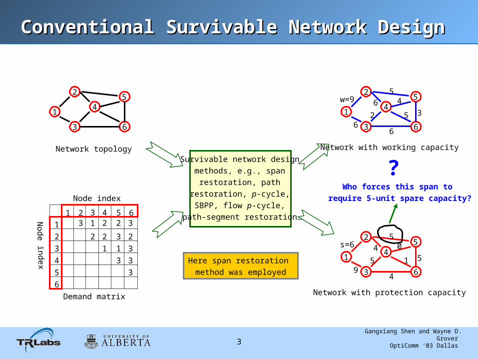
Conventional Survivable Network DesignConventional Survivable Network Design
1 2 3 4 5 6
1
2
3
4
5
6
Node index
Node in
dex
Demand matrix
3 1 2 2 3
2 2 3 2
1 1 3
3 3
3
2
3
4
6
1
Network topology
52
3
4
6
1
Network with working capacity
5w=9
6
6
2
6
54
5 3
2
3
4
6
1
Network with protection capacity
5s=6
9
4
5
4
50
1 5
Survivable network design methods, e.g., span
restoration, path restoration, p-cycle, SBPP, flow p-cycle,
path-segment restoration…
Here span restoration method was employed
? Who forces this span to
require 5-unit spare capacity?
Gangxiang Shen and Wayne D. Grover OptiComm ‘03 Dallas 4
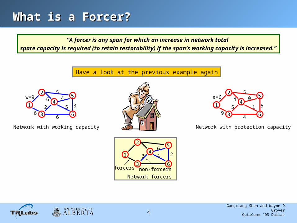
What is a Forcer?What is a Forcer?
“A forcer is any span for which an increase in network total spare capacity is required (to retain restorability) if the span’s working capacity is increased.”
Have a look at the previous example again
2
3
4
6
1
Network with working capacity
5w=9
6
6
2
6
54
5 3
2
3
4
6
1
Network with protection capacity
5s=6
9
4
5
4
50
1 5
2
3
4
6
1
Network forcers
5
forcers
3
6
4 2
non-forcers
Gangxiang Shen and Wayne D. Grover OptiComm ‘03 Dallas 5
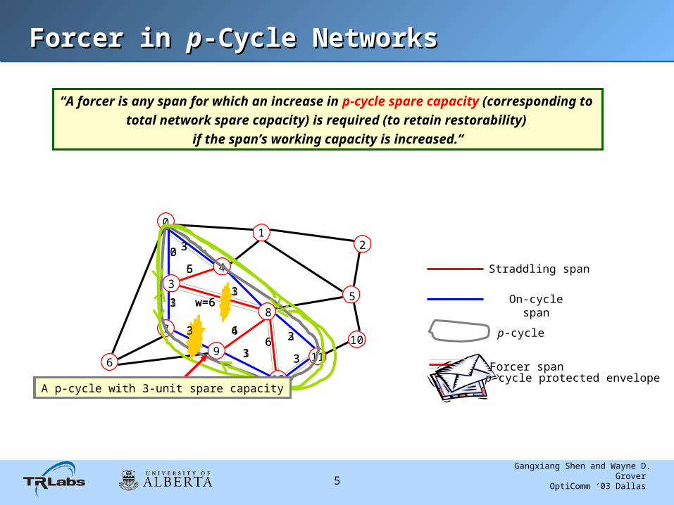
Forcer in Forcer in pp-Cycle Networks-Cycle Networks
0
11
3
7
69
12
10
12
4
58
Straddling span
On-cycle span
p-cycle
Forcer span
A p-cycle with 3-unit spare capacity
6
0
w=6
3
2
1
3
1
5
4
1
2
“A forcer is any span for which an increase in p-cycle spare capacity (corresponding to total network spare capacity) is required (to retain restorability)
if the span’s working capacity is increased.”
A p-cycle with 3-unit spare capacity
6
3
w=6
3
3
3
3
3
6
6
3
3
p-cycle protected envelope

Gangxiang Shen and Wayne D. Grover OptiComm ‘03 Dallas 6
Forcing Chain in Forcing Chain in pp-Cycle Networks-Cycle Networks
Span working capacity
Span working capacity
p-cycle protected envelopeProtected working capacity envelope
Span working capacity
Span protection capacity
How should we deal with this
gap?
p-cycle 3p-cycle 1p-cycle 2
p-cycle 4 p-cycle N
p-cycle spare capacity

Gangxiang Shen and Wayne D. Grover OptiComm ‘03 Dallas 7
How to Exploit the Gaps?How to Exploit the Gaps?
Forcer Filling: adding working capacity to non-forcers to make them forcers;
the added capacity can be used to serve future uncertain demands. … the basic idea of this paper
Protected working capacity envelope
Span working capacity
Protected working capacity envelope
Span working capacity after forcer filling Extra protected span working capacity for future uncertain demands
Just use it! No need to pay for anything for protection
!
Gangxiang Shen and Wayne D. Grover OptiComm ‘03 Dallas 8
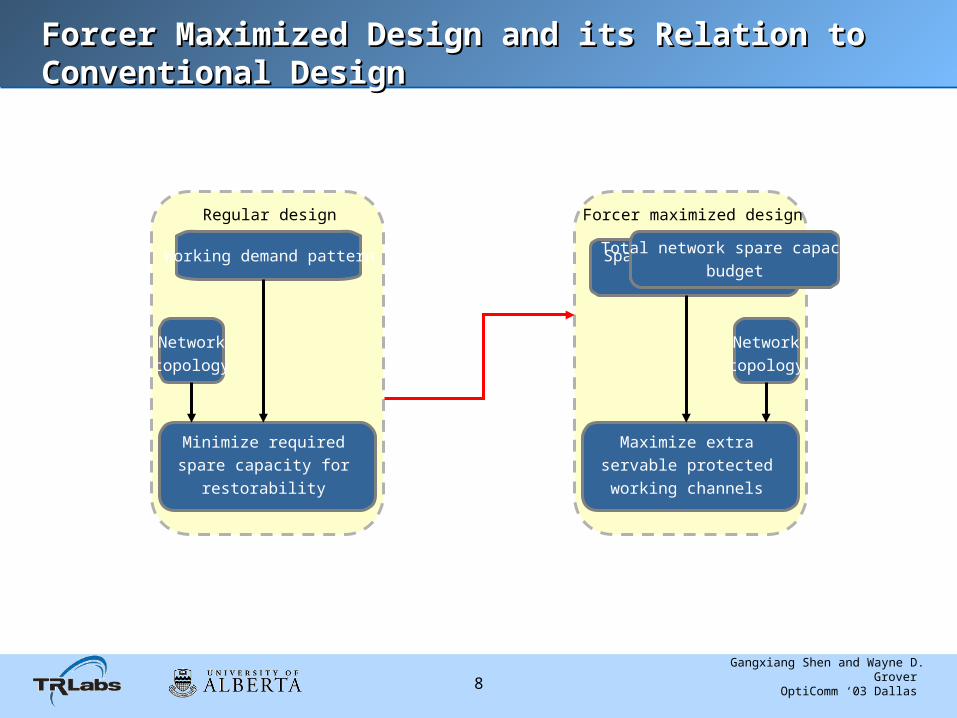
Forcer Maximized Design and its Relation to Forcer Maximized Design and its Relation to Conventional DesignConventional Design
Regular design
Working demand pattern
Networktopology
Minimize requiredspare capacity for
restorability
Forcer maximized design
Span spare capacitybudget
Maximize extraservable protectedworking channels
Networktopology
Total network spare capacitybudget

Gangxiang Shen and Wayne D. Grover OptiComm ‘03 Dallas 9
Three ILP ModelsThree ILP Models
• Common ground of the three models
--Objective: Maximize total servable protected working channels
--Conditions: 1. Ensure the restorability of working capacity
2. Ensure spare capacity shall be within budgets
• Forcer analyzer (FA) model
Maximize extra servable working channels, but disallowing to touch the existing working channels
• Forcer maximization-1 (FM-1)
Maximize servable working channels given span spare capacity budgets, but allowing to
change the existing working channels
• Forcer maximization-2 (FM-2)
Maximize servable working channels given total network spare capacity budgets, but allowing to change the existing working channels

Gangxiang Shen and Wayne D. Grover OptiComm ‘03 Dallas 10
Test Methods and Network TopologiesTest Methods and Network Topologies
1. Two metrics: hop-based and physical distance-based2. Dijkstra’s shortest path algorithm is used to find the route for a working path3. Demand matrixes are randomly generated within the range [1-20] for each node pair
NSFNET ARPA-2
SmallNet COST239

Gangxiang Shen and Wayne D. Grover OptiComm ‘03 Dallas 11
Test Methods and Network Topologies (cont’)Test Methods and Network Topologies (cont’)
Level-3 network

Gangxiang Shen and Wayne D. Grover OptiComm ‘03 Dallas 12
Results of the FA Model for Results of the FA Model for pp-Cycle Networks-Cycle Networks
0
10
20
30
40
50
60
70
80
90
Hop-based Distance-based
Pe
rce
nta
ge
s o
f e
xtr
a s
erv
ab
le w
ork
ing
ch
an
ne
ls w
ith
ou
t a
ny
inc
rea
se
in s
pa
rec
ap
ac
ity
bu
dg
et ARPA2
NSFNET
SmallNet
COST239
Level3
Percentages of extra working channels that can be served in p-cycle networks without any increase in span spare capacity budget

Gangxiang Shen and Wayne D. Grover OptiComm ‘03 Dallas 13
Redundancy Comparison between Various Survivable Redundancy Comparison between Various Survivable
SchemesSchemes
1: Conventional design 2: Forcer analyzer (FA) 3: Forcer maximization-1 (FM-1) 4: Forcer Maximization-2 (FM-2)

Gangxiang Shen and Wayne D. Grover OptiComm ‘03 Dallas 14
Concluding DiscussionConcluding Discussion
• A simple but efficient forcer analyzer is developed
• Two forcer maximization design models are proposed
• Experiments show that there is a rich “protected working capacity bank” under the forcer structure formed in the conventional survivable network design
• The direct use of protected capacity in the “bank” to serve future uncertain demands
……”Just use it! No need to pay any extra spare capacity for protection! (Its already protected)”
• Neighbouring concept to this study is to use “protected working capacity envelope (PWCE)” to serve dynamic protected demands for efficiency and simplicity
Thanks!

Gangxiang Shen and Wayne D. Grover OptiComm ‘03 Dallas 15
How to Deal with the Gaps?How to Deal with the Gaps? --Clipping and Filling--Clipping and Filling
Forcer Clipping: clipping forcers to make non-forcers become forcers as well
and to improve network spare capacity efficiency
Protected working capacity envelope
Span working capacity
Protected working capacity envelope
Remaining span working capacity Clipped span working capacity
Ring covering