failing to fail: achieving success in advanced low power ... to fail upf tutorial .pdf · • upf...
TRANSCRIPT
International Symposium on Low Power Electronics and Design
Failing to Fail: Achieving Success in Advanced Low Power Design using UPF
1Rick Koster, 2John Redmond, and 3Shreedhar Ramachandra
1Mentor Graphics Corporation 2Broadcom Corporation
3Synopsys Inc.
International Symposium on Low Power Electronics and Design
UPF Overview
Rick Koster
Mentor Graphics
Agenda
• UPF Overview – Low Power Management Concepts
– What is UPF
– Power Management Structures
– Power Management Behavior
3
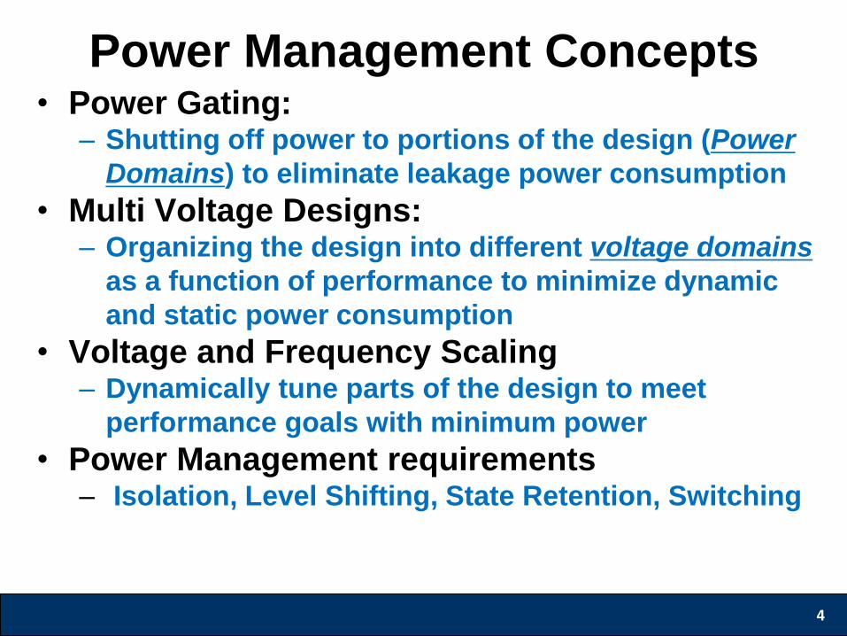
Power Management Concepts • Power Gating:
– Shutting off power to portions of the design (Power
Domains) to eliminate leakage power consumption
• Multi Voltage Designs: – Organizing the design into different voltage domains
as a function of performance to minimize dynamic
and static power consumption
• Voltage and Frequency Scaling – Dynamically tune parts of the design to meet
performance goals with minimum power
• Power Management requirements – Isolation, Level Shifting, State Retention, Switching
4
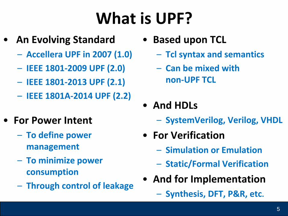
What is UPF? • An Evolving Standard
– Accellera UPF in 2007 (1.0)
– IEEE 1801-2009 UPF (2.0)
– IEEE 1801-2013 UPF (2.1)
– IEEE 1801A-2014 UPF (2.2)
• For Power Intent
– To define power management
– To minimize power consumption
– Through control of leakage
• Based upon TCL
– Tcl syntax and semantics
– Can be mixed with non-UPF TCL
• And HDLs
– SystemVerilog, Verilog, VHDL
• For Verification
– Simulation or Emulation
– Static/Formal Verification
• And for Implementation
– Synthesis, DFT, P&R, etc.
5

Power Management Structures
• Power Domains
• Domain Interfaces (ISO/LS)
• Retention
• Supply Sets
• Supply Ports/Nets
• Power Switches
6
Power Domains • A collection of instances that are treated as a
group for power-management purposes.
• A Power domain exists within a logical scope – UPF and HDL identifiers must be unique within the
scope
– All UPF commands are executed within the current active scope
• A power domain can have associated with it isolation strategies, retention strategies and level shifter requirements
7
8
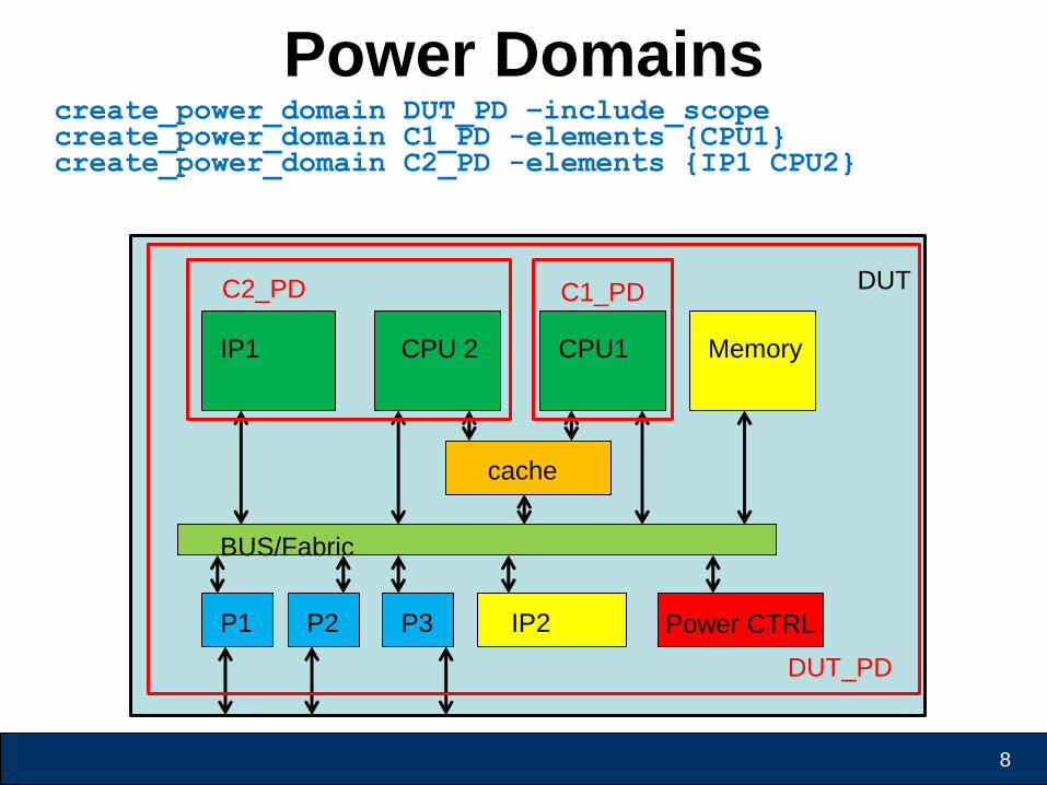
Power Domains
DUT
IP1 CPU 2
cache
BUS/Fabric
CPU1 Memory
P1 P2 P3 IP2 Power CTRL
C1_PD C2_PD
DUT_PD
create_power_domain DUT_PD –include_scope create_power_domain C1_PD -elements {CPU1} create_power_domain C2_PD -elements {IP1 CPU2}
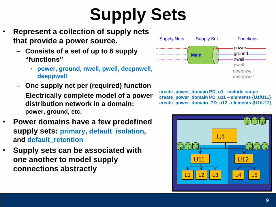
Supply Sets • Represent a collection of supply nets
that provide a power source.
– Consists of a set of up to 6 supply
“functions”
• power, ground, nwell, pwell, deepnwell,
deeppwell
– One supply net per (required) function
– Electrically complete model of a power
distribution network in a domain: power, ground, etc.
• Power domains have a few predefined
supply sets: primary, default_isolation,
and default_retention
• Supply sets can be associated with
one another to model supply
connections abstractly
9
deepnwell
deeppwell
power
ground
nwell Main
pwell
Functions Supply Nets Supply Set
U11 U12
L1 L2 L3 L4 L5
P R I
P R I P R I
U1
create_power_domain PD_u1 –include scope
create_power_domain PD_u11 – elements {U1/U11}
create_power_domain PD_u12 –elements {U1/U12}
Domain Interfaces • Power gating can cause electrical and logical
problems to adjacent domains.
– Isolation is used to prevent these problems.
– Isolation cell: An instance that passes logic values during
normal mode operation and clamps its output to some specified
logic value when a control signal is asserted.
• Multi voltage designs can also experience
problems
– Level shifters are used to maintain signal integrity.
• Level shifter cell: An instance that translates signal values from
an input voltage swing to a different output voltage swing.
10
Retention/Repeaters • Device operation may require the use of flip
flops or memories that preserve state during a
domain’s power down.
• Preserving state is achieve through the use of
UPF retention.
– Retention: Enhanced functionality associated with
selected sequential elements or a memory such that
memory values can be preserved during the power-
down state of the primary supplies.
11
Supply Ports/Nets • Power Domain supply sets consist of supply
nets that eventually are driven by supply ports
• Supply ports and nets are defined as objects of
supply_net_type
• UPF package defines supply_net_type as:
typedef enum
(OFF=0,UNDETERMINED, PARTIAL_ON, FULL_ON) state
typedef struct packed {
state state;
int voltage; // voltage in microVolts
} supply_net_type;
12
Power Switches
• A power switch is a design element that
conditionally connects input supply nets to an
output supply net
• A UPF switch can be on or off or partially on
• The state of the switch is set by Boolean
functions of the control ports
• Match = input voltage propagates to output (on)
• No Match = output port disabled (off)
• Either power or ground can be switched
13
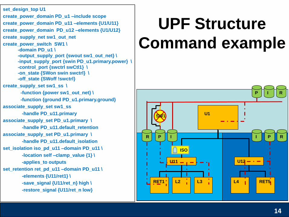
set_design_top U1
create_power_domain PD_u1 –include scope
create_power_domain PD_u11 –elements {U1/U11}
create_power_domain PD_u12 –elements {U1/U12}
create_supply_net sw1_out_net
create_power_switch SW1 \
-domain PD_u1 \
-output_supply_port {swout sw1_out_net} \
-input_supply_port {swin PD_u1.primary.power} \
-control_port {swctrl swCtl1} \
-on_state {SWon swin swctrl} \
-off_state {SWoff !swctrl}
create_supply_set sw1_ss \
-function {power sw1_out_net} \
-function {ground PD_u1.primary.ground}
associate_supply_set sw1_ss
-handle PD_u11.primary
associate_supply_set PD_u1.primary \
-handle PD_u11.default_retention
associate_supply_set PD_u1.primary \
-handle PD_u11.default_isolation
set_isolation iso_pd_u11 –domain PD_u11 \
-location self –clamp_value {1} \
-applies_to outputs
set_retention ret_pd_u11 –domain PD_u11 \
-elements {U11/ret1} \
-save_signal {U11/ret_n} high \
-restore_signal {U11/ret_n low}
U11 U12
RET1 L2 L3 L4 RET5
P R I
R I P I R P
U1 SW1
ISO
UPF Structure
Command example
14
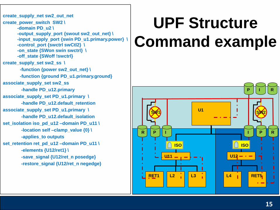
create_supply_net sw2_out_net
create_power_switch SW2 \
-domain PD_u2 \
-output_supply_port {swout sw2_out_net} \
-input_supply_port {swin PD_u1.primary.power} \
-control_port {swctrl swCtl2} \
-on_state {SWon swin swctrl} \
-off_state {SWoff !swctrl}
create_supply_set sw2_ss \
-function {power sw2_out_net} \
-function {ground PD_u1.primary.ground}
associate_supply_set sw2_ss
-handle PD_u12.primary
associate_supply_set PD_u1.primary \
-handle PD_u12.default_retention
associate_supply_set PD_u1.primary \
-handle PD_u12.default_isolation
set_isolation iso_pd_u12 –domain PD_u11 \
-location self –clamp_value {0} \
-applies_to outputs
set_retention ret_pd_u12 –domain PD_u11 \
-elements {U12/ret1} \
-save_signal {U12/ret_n posedge}
-restore_signal {U12/ret_n negedge}
U11 U12
RET1 L2 L3 L4 RET5
P R I
R I P I R P
U1 SW1 SW2
ISO ISO
UPF Structure
Command example
15
Behavior
• Supply set Power States
• Simstates
• Power Domain States
16
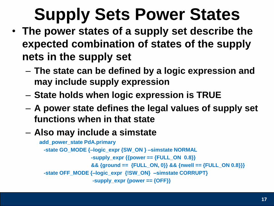
Supply Sets Power States • The power states of a supply set describe the
expected combination of states of the supply
nets in the supply set
– The state can be defined by a logic expression and
may include supply expression
– State holds when logic expression is TRUE
– A power state defines the legal values of supply set
functions when in that state
– Also may include a simstate add_power_state PdA.primary
-state GO_MODE {–logic_expr {SW_ON } –simstate NORMAL
-supply_expr {{power == {FULL_ON 0.8}}
&& {ground == {FULL_ON, 0}} && {nwell == {FULL_ON 0.8}}}
-state OFF_MODE {–logic_expr {!SW_ON} –simstate CORRUPT}
-supply_expr {power == {OFF}}
17
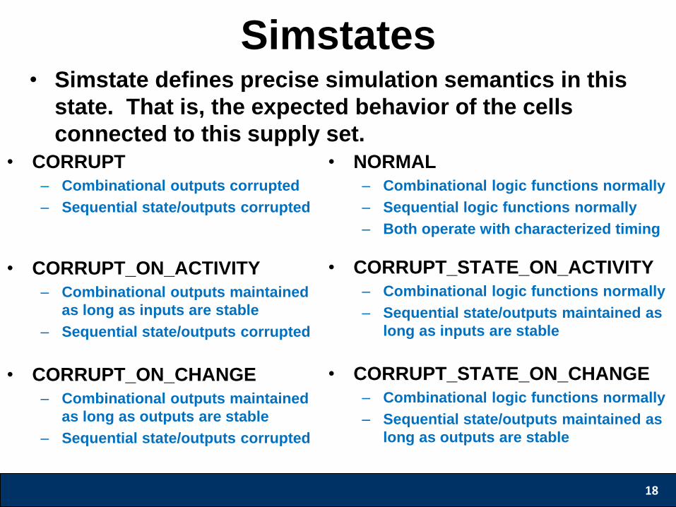
Simstates • Simstate defines precise simulation semantics in this
state. That is, the expected behavior of the cells
connected to this supply set.
18
• CORRUPT
– Combinational outputs corrupted
– Sequential state/outputs corrupted
• CORRUPT_ON_ACTIVITY
– Combinational outputs maintained
as long as inputs are stable
– Sequential state/outputs corrupted
• CORRUPT_ON_CHANGE
– Combinational outputs maintained
as long as outputs are stable
– Sequential state/outputs corrupted
• NORMAL
– Combinational logic functions normally
– Sequential logic functions normally
– Both operate with characterized timing
• CORRUPT_STATE_ON_ACTIVITY
– Combinational logic functions normally
– Sequential state/outputs maintained as
long as inputs are stable
• CORRUPT_STATE_ON_CHANGE
– Combinational logic functions normally
– Sequential state/outputs maintained as
long as outputs are stable

Power States of a Power Domain
• A power domain is designed to have a set of
allowable states in which it can operate.
• The domain power states describe the
allowable set of states for a domain. Each
state is defined by a logic expression
– Logic expressions can be created with:
• States of supply_sets
• Logic port and net values
• Subdomain power states
• Interval Functions
19
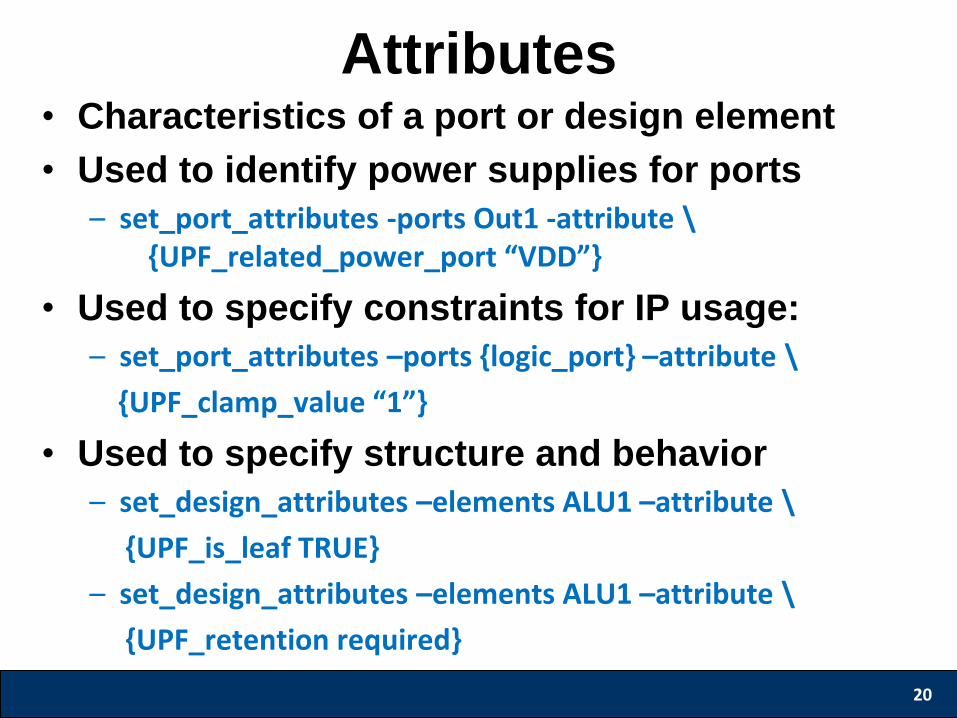
Attributes • Characteristics of a port or design element
• Used to identify power supplies for ports
– set_port_attributes -ports Out1 -attribute \ {UPF_related_power_port “VDD”}
• Used to specify constraints for IP usage:
– set_port_attributes –ports {logic_port} –attribute \
{UPF_clamp_value “1”}
• Used to specify structure and behavior
– set_design_attributes –elements ALU1 –attribute \
{UPF_is_leaf TRUE}
– set_design_attributes –elements ALU1 –attribute \
{UPF_retention required}
20
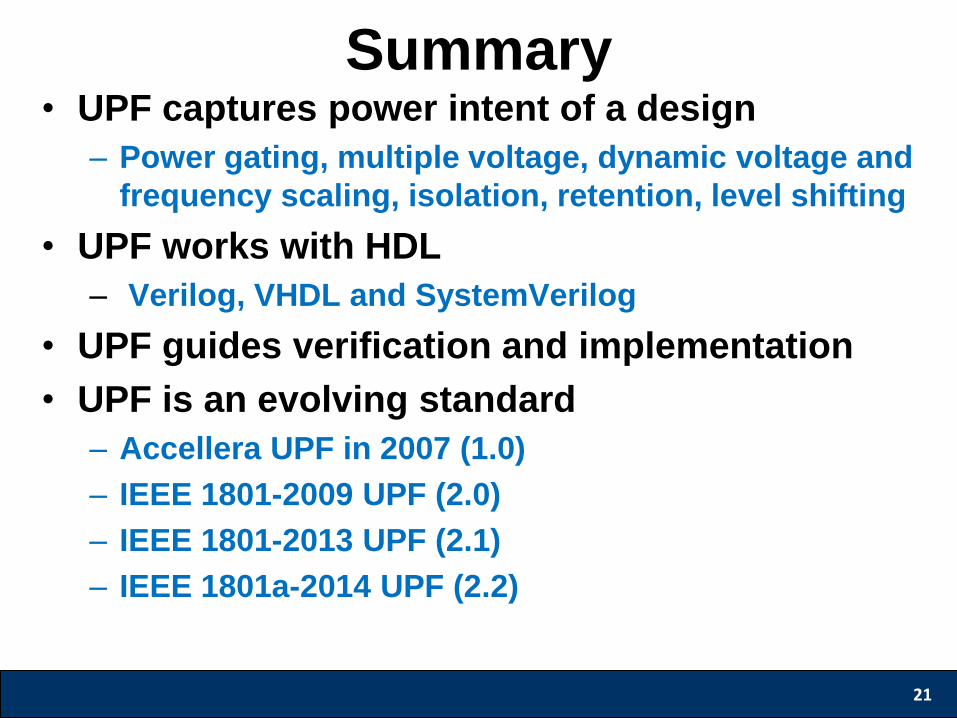
• UPF captures power intent of a design
– Power gating, multiple voltage, dynamic voltage and
frequency scaling, isolation, retention, level shifting
• UPF works with HDL
– Verilog, VHDL and SystemVerilog
• UPF guides verification and implementation
• UPF is an evolving standard
– Accellera UPF in 2007 (1.0)
– IEEE 1801-2009 UPF (2.0)
– IEEE 1801-2013 UPF (2.1)
– IEEE 1801a-2014 UPF (2.2)
21
Summary
International Symposium on Low Power Electronics and Design
UPF For ASIC Design
John Redmond *
Broadcom Corporation
* Slides contributed by Sushma Honnavara-Prasad
• Introduction
– How power intent is realized in silicon
– Leaf Cells and macro models
• Soft IP modeling
– Successive refinement
– Constraints, configuration, implementation
• SoC integration
– Hierarchical UPF composition
– Supply network construction
– System power states and transitions
23
Agenda
• Power intent is captured through UPF, HDL and Library
• UPF realizes:
– Supply network specification
• power/ground/nwell/pwell/deepnwell/deeppwell
• Macro and IO power connectivity
• On-chip power switch specification
– Power domain specification
• Identify a standard cell region, supply availability in a region
– Strategies and their implementation
• Dictates inference of isolation cells, level shifters, repeaters and retention cells
• Leaf cell/macros need models to identify supply pins
– Liberty (.lib) provides UPF attributes
– LEF identifies power/ground/signal pins
– 1801-2013 enables cell and macro modeling
24
Introduction
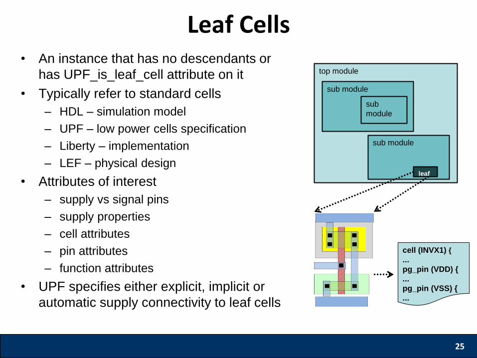
• An instance that has no descendants or
has UPF_is_leaf_cell attribute on it
• Typically refer to standard cells
– HDL – simulation model
– UPF – low power cells specification
– Liberty – implementation
– LEF – physical design
• Attributes of interest
– supply vs signal pins
– supply properties
– cell attributes
– pin attributes
– function attributes
• UPF specifies either explicit, implicit or
automatic supply connectivity to leaf cells
25
Leaf Cells
top module
sub module
leaf
sub module
sub
module
cell (INVX1) {
...
pg_pin (VDD) {
...
pg_pin (VSS) {
...
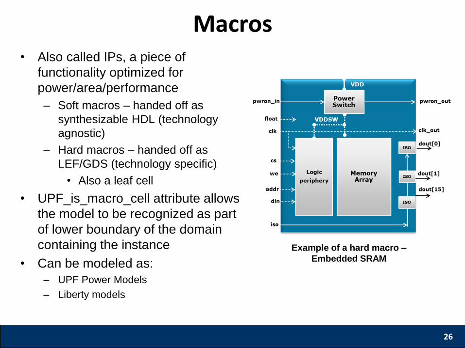
• Also called IPs, a piece of
functionality optimized for
power/area/performance
– Soft macros – handed off as
synthesizable HDL (technology
agnostic)
– Hard macros – handed off as
LEF/GDS (technology specific)
• Also a leaf cell
• UPF_is_macro_cell attribute allows
the model to be recognized as part
of lower boundary of the domain
containing the instance
• Can be modeled as:
– UPF Power Models
– Liberty models
26
Macros
Example of a hard macro –
Embedded SRAM
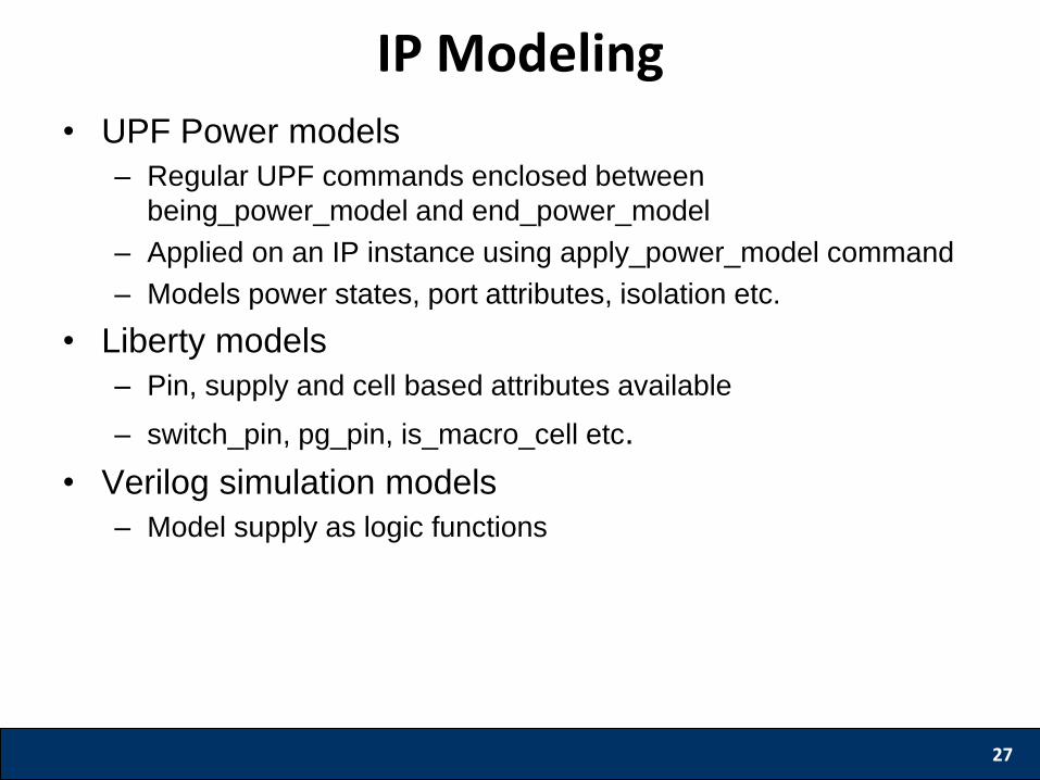
• UPF Power models
– Regular UPF commands enclosed between
being_power_model and end_power_model
– Applied on an IP instance using apply_power_model command
– Models power states, port attributes, isolation etc.
• Liberty models
– Pin, supply and cell based attributes available
– switch_pin, pg_pin, is_macro_cell etc.
• Verilog simulation models
– Model supply as logic functions
27
IP Modeling
28
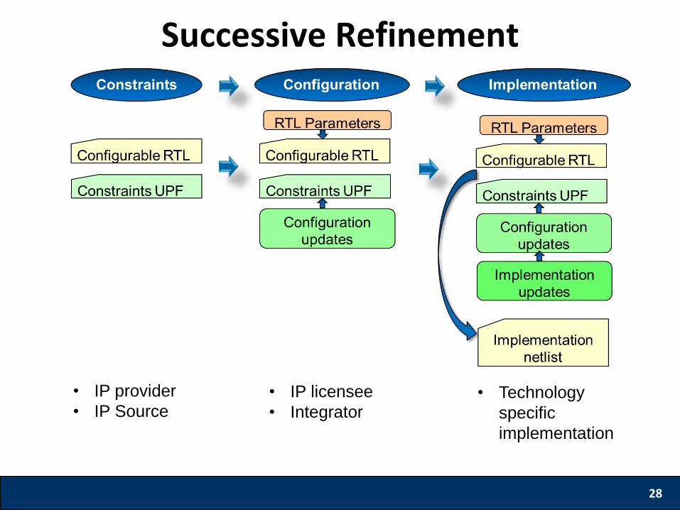
Successive Refinement
• IP provider
• IP Source • IP licensee
• Integrator • Technology
specific
implementation
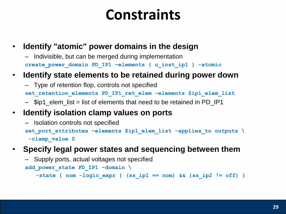
• Identify "atomic" power domains in the design
– Indivisible, but can be merged during implementation
create_power_domain PD_IP1 –elements { u_inst_ip1 } -atomic
• Identify state elements to be retained during power down
– Type of retention flop, controls not specified
set_retention_elements PD_IP1_ret_elem –elements $ip1_elem_list
– $ip1_elem_list = list of elements that need to be retained in PD_IP1
• Identify isolation clamp values on ports
– Isolation controls not specified
set_port_attributes –elements $ip1_elem_list -applies_to outputs \
-clamp_value 0
• Specify legal power states and sequencing between them
– Supply ports, actual voltages not specified
add_power_state PD_IP1 –domain \
-state { nom -logic_expr { (ss_ip1 == nom) && {ss_ip2 != off) }
29
Constraints
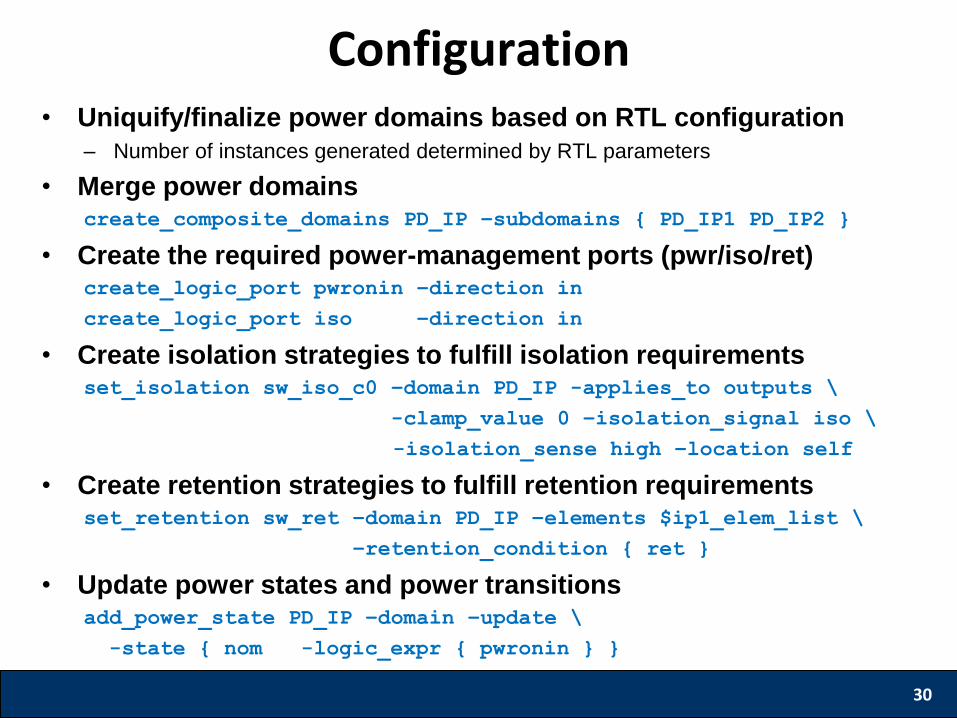
• Uniquify/finalize power domains based on RTL configuration
– Number of instances generated determined by RTL parameters
• Merge power domains create_composite_domains PD_IP –subdomains { PD_IP1 PD_IP2 }
• Create the required power-management ports (pwr/iso/ret) create_logic_port pwronin –direction in
create_logic_port iso –direction in
• Create isolation strategies to fulfill isolation requirements set_isolation sw_iso_c0 –domain PD_IP -applies_to outputs \
-clamp_value 0 –isolation_signal iso \
-isolation_sense high –location self
• Create retention strategies to fulfill retention requirements set_retention sw_ret –domain PD_IP –elements $ip1_elem_list \
–retention_condition { ret }
• Update power states and power transitions add_power_state PD_IP –domain –update \
-state { nom -logic_expr { pwronin } }
30
Configuration

• Create supply ports and nets create_supply_port VDD1 –direction in
create_supply_net VSS –domain PD_SUB1 -reuse
• Update supply set functions create_supply_set ss_ip1 –update –function {power VDD1} \
-function {ground VSS}
• Update power states with supply values add_power_state ss_ip1 –update –supply \
-state {nom -supply_expr {(power == {FULL_ON 0.9}) && (ground == {FULL_ON 0})}
• Create power-switches create_power_switch PSW_PD_IP –domain PD_IP \
-input_supply_port { in_vdd VDDB } \
-output_supply_port { out_vdd VDD } \
-control_port { sw_ctrl pwronin } \
-on_state { full_on in_vdd {sw_ctrl} } \
-off_state { full_off {!sw_ctrl} }
• Map strategies to technology specific library cells use_interface_cell sw_low -strategy sw_iso_c0 -domain PD_IP \
-lib_cells $list_lib_cells
31
Implementation
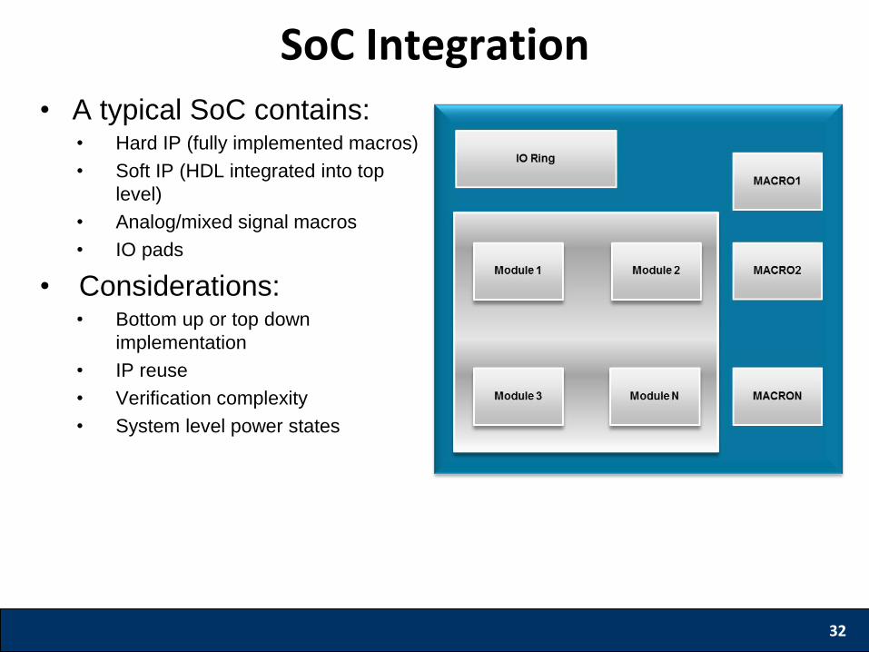
• A typical SoC contains: • Hard IP (fully implemented macros)
• Soft IP (HDL integrated into top
level)
• Analog/mixed signal macros
• IO pads
• Considerations: • Bottom up or top down
implementation
• IP reuse
• Verification complexity
• System level power states
32
SoC Integration
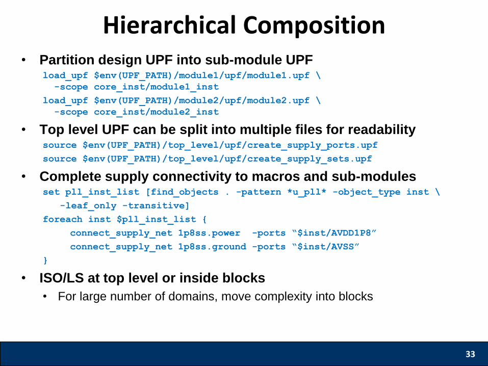
• Partition design UPF into sub-module UPF load_upf $env(UPF_PATH)/module1/upf/module1.upf \
-scope core_inst/module1_inst
load_upf $env(UPF_PATH)/module2/upf/module2.upf \
-scope core_inst/module2_inst
• Top level UPF can be split into multiple files for readability source $env(UPF_PATH)/top_level/upf/create_supply_ports.upf
source $env(UPF_PATH)/top_level/upf/create_supply_sets.upf
• Complete supply connectivity to macros and sub-modules set pll_inst_list [find_objects . -pattern *u_pll* -object_type inst \
-leaf_only -transitive]
foreach inst $pll_inst_list {
connect_supply_net 1p8ss.power -ports “$inst/AVDD1P8”
connect_supply_net 1p8ss.ground -ports “$inst/AVSS”
}
• ISO/LS at top level or inside blocks
• For large number of domains, move complexity into blocks
33
Hierarchical Composition
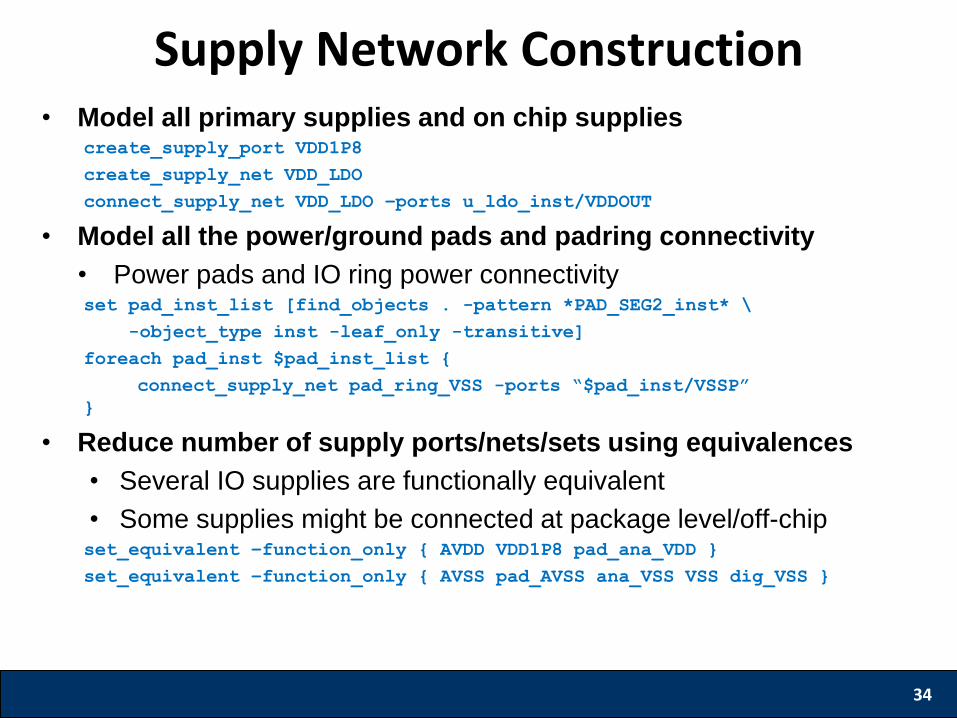
• Model all primary supplies and on chip supplies create_supply_port VDD1P8
create_supply_net VDD_LDO
connect_supply_net VDD_LDO –ports u_ldo_inst/VDDOUT
• Model all the power/ground pads and padring connectivity
• Power pads and IO ring power connectivity set pad_inst_list [find_objects . -pattern *PAD_SEG2_inst* \
-object_type inst -leaf_only -transitive]
foreach pad_inst $pad_inst_list {
connect_supply_net pad_ring_VSS -ports “$pad_inst/VSSP”
}
• Reduce number of supply ports/nets/sets using equivalences
• Several IO supplies are functionally equivalent
• Some supplies might be connected at package level/off-chip set_equivalent –function_only { AVDD VDD1P8 pad_ana_VDD }
set_equivalent –function_only { AVSS pad_AVSS ana_VSS VSS dig_VSS }
34
Supply Network Construction
35
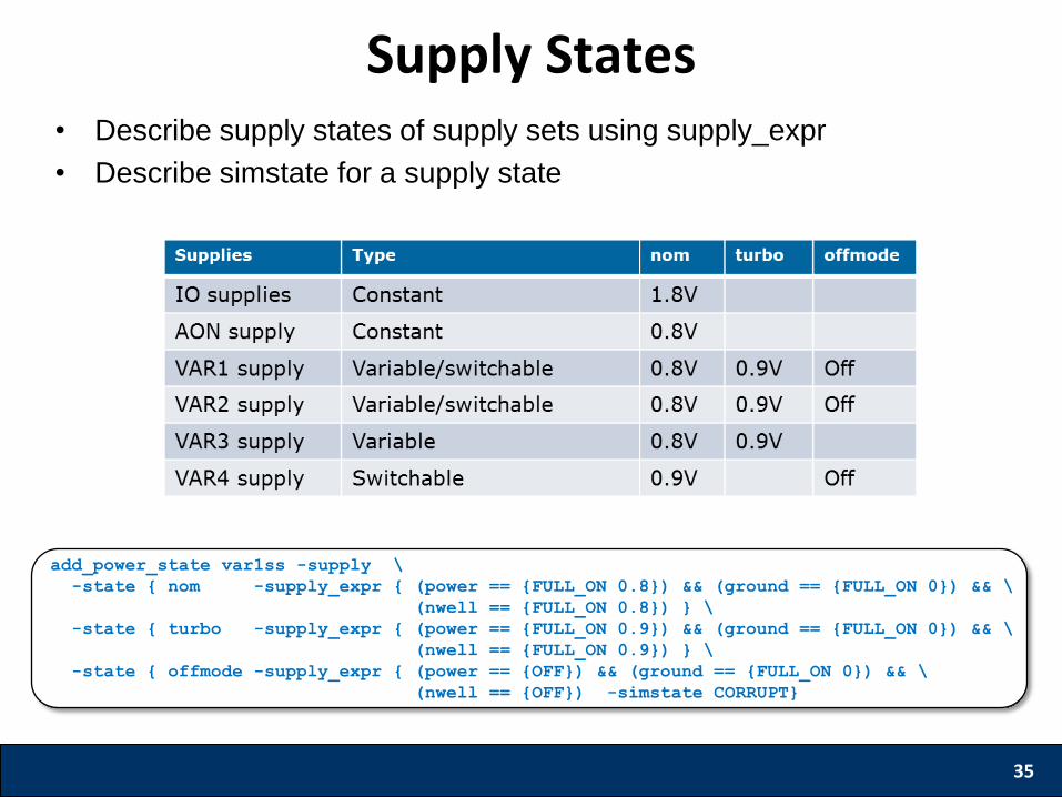
Supply States
add_power_state var1ss -supply \
-state { nom -supply_expr { (power == {FULL_ON 0.8}) && (ground == {FULL_ON 0}) && \
(nwell == {FULL_ON 0.8}) } \
-state { turbo -supply_expr { (power == {FULL_ON 0.9}) && (ground == {FULL_ON 0}) && \
(nwell == {FULL_ON 0.9}) } \
-state { offmode -supply_expr { (power == {OFF}) && (ground == {FULL_ON 0}) && \
(nwell == {OFF}) -simstate CORRUPT}
• Describe supply states of supply sets using supply_expr
• Describe simstate for a supply state
36
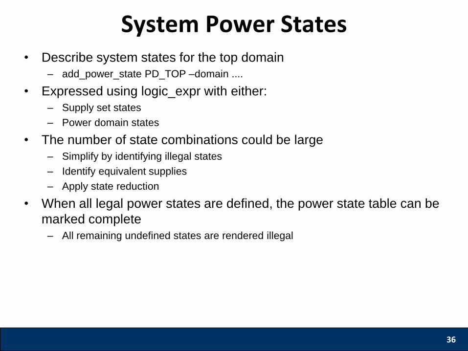
System Power States • Describe system states for the top domain
– add_power_state PD_TOP –domain ....
• Expressed using logic_expr with either:
– Supply set states
– Power domain states
• The number of state combinations could be large
– Simplify by identifying illegal states
– Identify equivalent supplies
– Apply state reduction
• When all legal power states are defined, the power state table can be
marked complete
– All remaining undefined states are rendered illegal
37
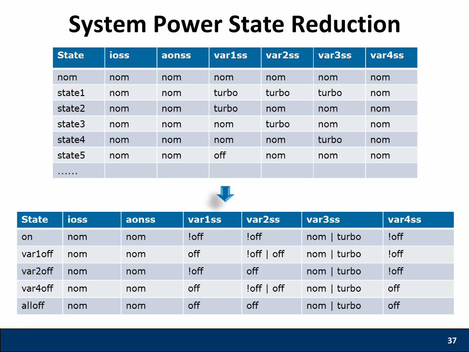
System Power State Reduction
38
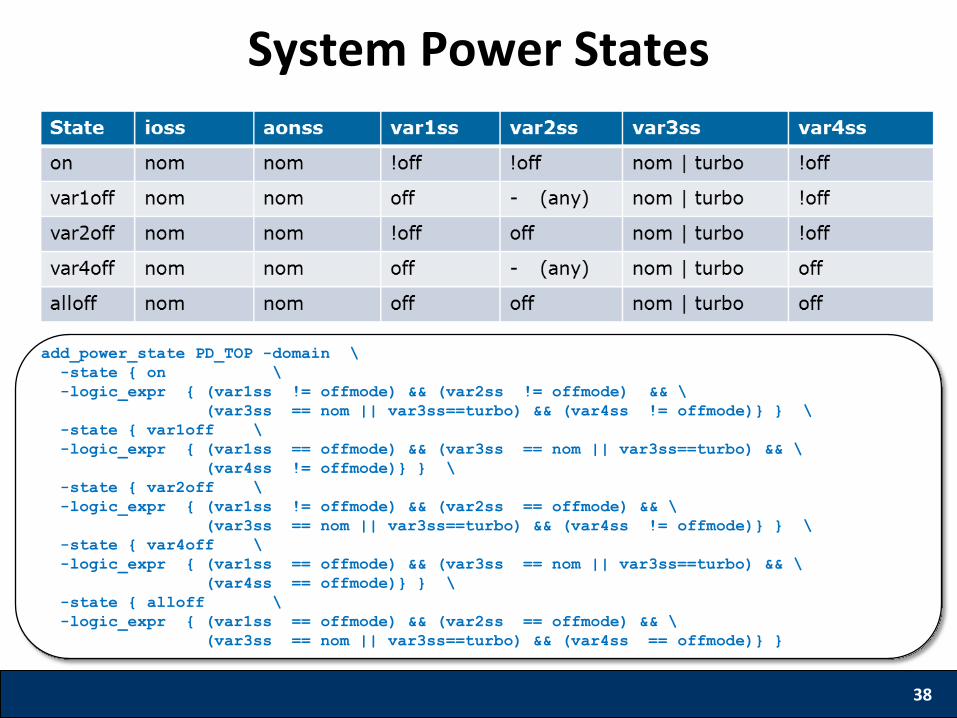
System Power States
add_power_state PD_TOP -domain \
-state { on \
-logic_expr { (var1ss != offmode) && (var2ss != offmode) && \
(var3ss == nom || var3ss==turbo) && (var4ss != offmode)} } \
-state { var1off \
-logic_expr { (var1ss == offmode) && (var3ss == nom || var3ss==turbo) && \
(var4ss != offmode)} } \
-state { var2off \
-logic_expr { (var1ss != offmode) && (var2ss == offmode) && \
(var3ss == nom || var3ss==turbo) && (var4ss != offmode)} } \
-state { var4off \
-logic_expr { (var1ss == offmode) && (var3ss == nom || var3ss==turbo) && \
(var4ss == offmode)} } \
-state { alloff \
-logic_expr { (var1ss == offmode) && (var2ss == offmode) && \
(var3ss == nom || var3ss==turbo) && (var4ss == offmode)} }
39
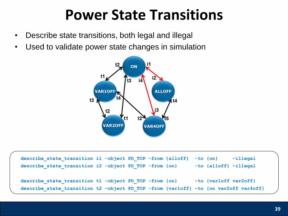
Power State Transitions
describe_state_transition i1 -object PD_TOP -from {alloff} -to {on} –illegal
describe_state_transition i2 -object PD_TOP -from {on} -to {alloff} –illegal
describe_state_transition t1 –object PD_TOP -from {on} –to {var1off var2off}
describe_state_transition t2 –object PD_TOP -from {var1off} –to {on var2off var4off}
• Describe state transitions, both legal and illegal
• Used to validate power state changes in simulation
• Power intent is augmented based on design phase by a
process of successive refinement
• Soft IP providers deliver UPF constraints, IP integrator
configures it to deliver technology agnostic UPF
• Implementation UPF commands allow for technology
specific design
• SoC UPF is hierarchically composed of sub-module UPF
• SoC supplies, supply states, power states and state
transitions can be modeled in UPF
40
Summary
International Symposium on Low Power Electronics and Design
Power Aware Verification
Shreedhar Ramachandra
Synopsys Inc.
Agenda • Introduction
• Power Aware Static Verification
• Power Aware Simulation
• Power Aware Coverage
42
Introduction • Traditional verification does not involve
voltage/power transitions
• Power Aware Verification – Verify the complex power management schemes – Make sure that the design can successfully function in all
the power states for which it is designed
• Power related bugs – Structural – Control Sequencing – Power Management Architecture
43
Static Verification
44
Static Verification
Tool
(Performs Analysis)
HDL
(DUT)
Liberty
(.lib)
UPF
Reports
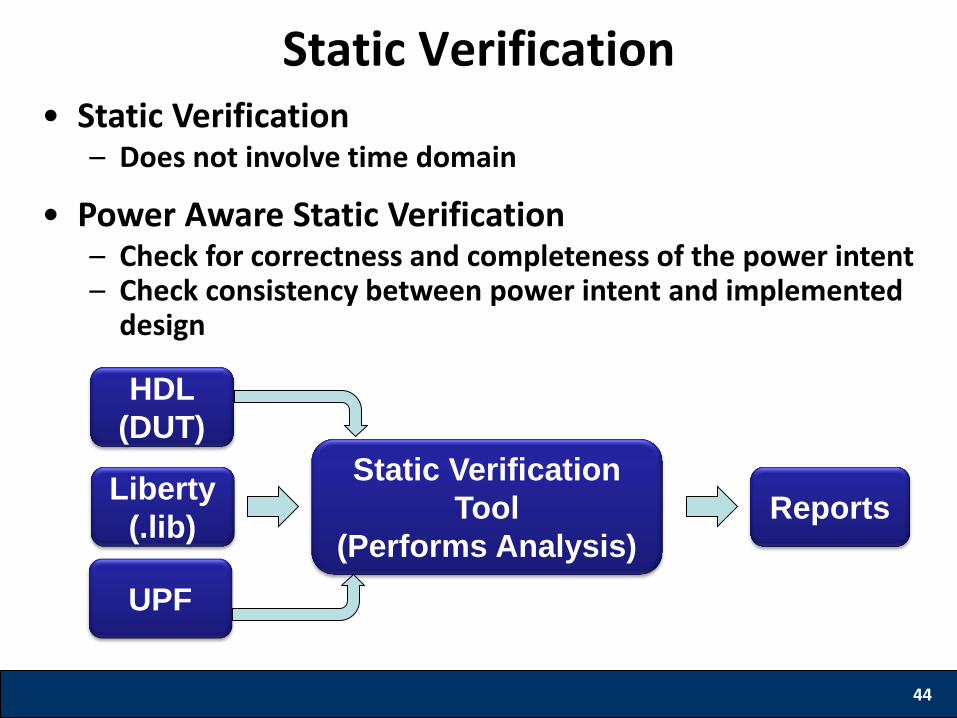
• Static Verification – Does not involve time domain
• Power Aware Static Verification – Check for correctness and completeness of the power intent – Check consistency between power intent and implemented
design

Static Verification: Power State Analysis
• ISO requirement
– Find OFF->ON paths, which contribute to leakage power
• LS requirement
– Find paths where there is voltage difference between source and sink
45
VAO VCORE VMEM1 VMEM2
St1 1.2 0.8 0.8 0.8
St2 1.2 0.8 0.8 OFF
St3 0.8 0.8 OFF OFF
St4 0.8 OFF OFF OFF
St5 OFF OFF OFF OFF
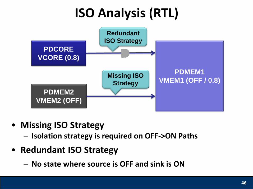
ISO Analysis (RTL)
• Missing ISO Strategy – Isolation strategy is required on OFF->ON Paths
• Redundant ISO Strategy
– No state where source is OFF and sink is ON
46
PDCORE
VCORE (0.8)
PDMEM1
VMEM1 (OFF / 0.8)
PDMEM2
VMEM2 (OFF)
Missing ISO
Strategy
Redundant
ISO Strategy
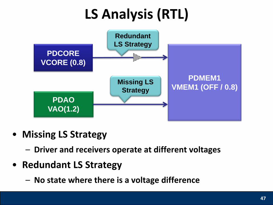
LS Analysis (RTL)
• Missing LS Strategy
– Driver and receivers operate at different voltages
• Redundant LS Strategy
– No state where there is a voltage difference
47
PDAO
VAO(1.2)
PDCORE
VCORE (0.8)
PDMEM1
VMEM1 (OFF / 0.8)
Redundant
LS Strategy
Missing LS
Strategy
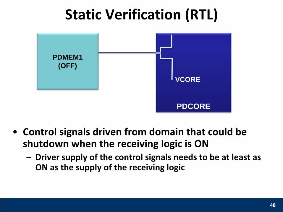
Static Verification (RTL)
• Control signals driven from domain that could be shutdown when the receiving logic is ON – Driver supply of the control signals needs to be at least as
ON as the supply of the receiving logic
48
PDCORE
PDMEM1
(OFF)
VCORE
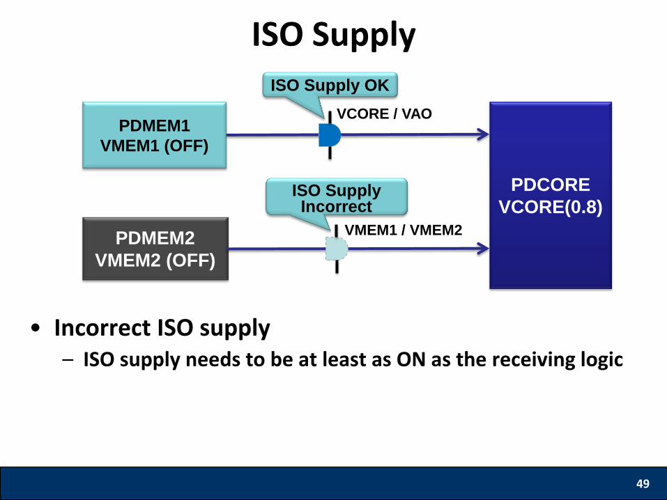
ISO Supply
• Incorrect ISO supply – ISO supply needs to be at least as ON as the receiving logic
49
PDMEM1
VMEM1 (OFF)
PDCORE
VCORE(0.8)
PDMEM2
VMEM2 (OFF)
ISO Supply OK
ISO Supply Incorrect
VCORE / VAO
VMEM1 / VMEM2
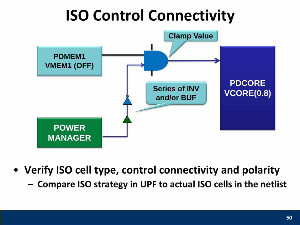
ISO Control Connectivity
• Verify ISO cell type, control connectivity and polarity – Compare ISO strategy in UPF to actual ISO cells in the netlist
50
PDMEM1
VMEM1 (OFF)
Series of INV
and/or BUF
POWER
MANAGER
Clamp Value
PDCORE
VCORE(0.8)
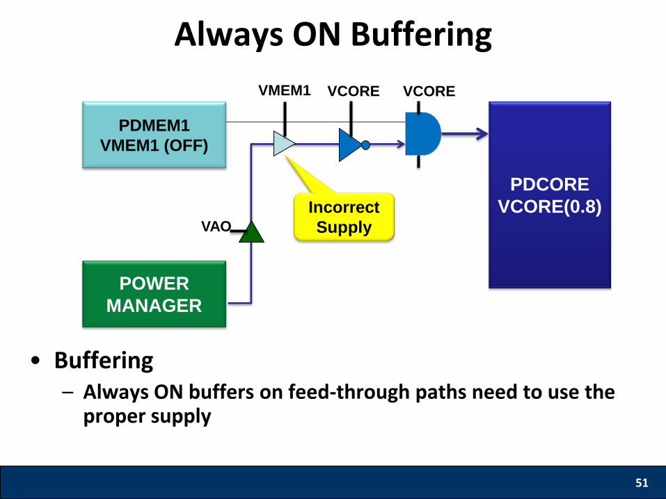
Always ON Buffering
• Buffering – Always ON buffers on feed-through paths need to use the
proper supply
51
PDMEM1
VMEM1 (OFF)
POWER
MANAGER
VCORE VCORE
VAO
VMEM1
Incorrect
Supply
PDCORE
VCORE(0.8)

Power Aware Simulation (RTL) • Functional Simulation
– Doesn’t take into account the Power related effects
• Power Aware Simulation – Simulates the effects due to Power related changes
– Catch Control Sequence and Architectural bugs
52
Power Aware
Simulator
HDL (DUT)
Libraries (.v,
.sv, .vhd, .lib)
UPF
Reports Power aware
Testbench
Waveform
Coverage
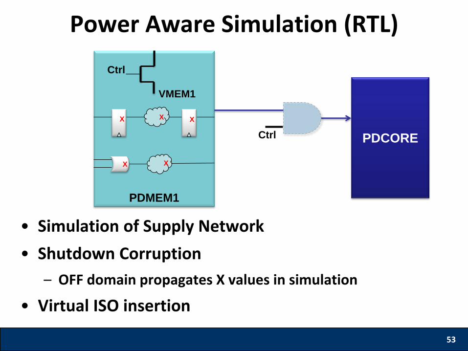
Power Aware Simulation (RTL)
• Simulation of Supply Network
• Shutdown Corruption
– OFF domain propagates X values in simulation
• Virtual ISO insertion
53
PDMEM1
X X
X
X
X
PDCORE
Ctrl
VMEM1
Ctrl
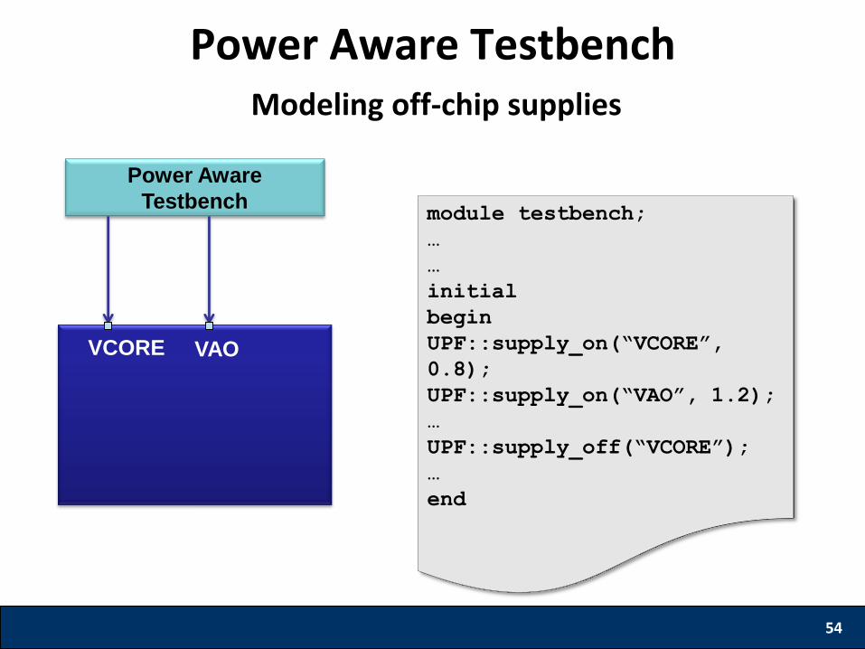
Power Aware Testbench
54
Power Aware
Testbench
VCORE VAO
module testbench;
…
…
initial
begin
UPF::supply_on(“VCORE”,
0.8);
UPF::supply_on(“VAO”, 1.2);
…
UPF::supply_off(“VCORE”);
…
end
Modeling off-chip supplies
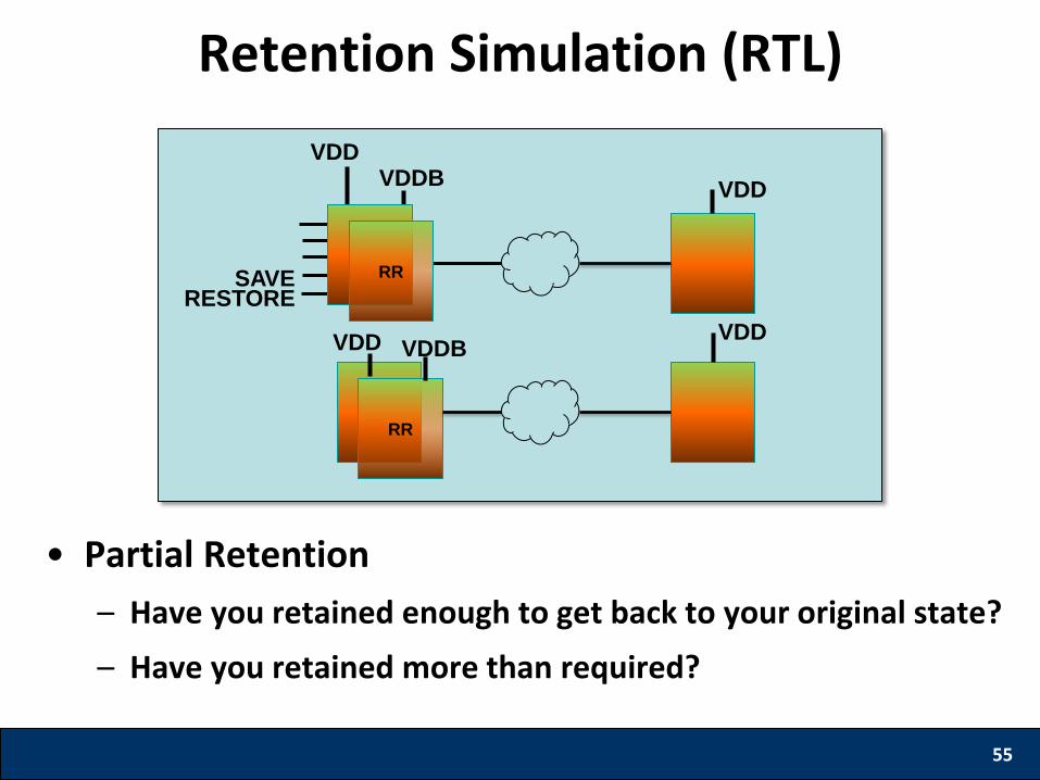
Retention Simulation (RTL)
• Partial Retention
– Have you retained enough to get back to your original state?
– Have you retained more than required?
55
VDDB VDD
SAVE RESTORE
RR
RR
VDD
VDD VDDB VDD
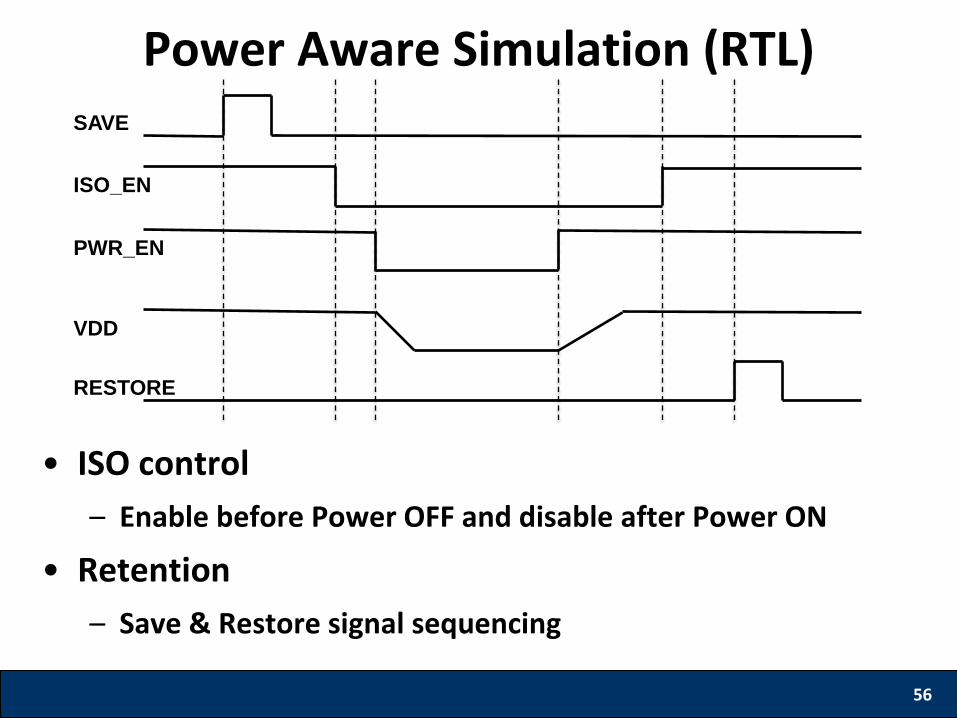
Power Aware Simulation (RTL)
• ISO control
– Enable before Power OFF and disable after Power ON
• Retention
– Save & Restore signal sequencing
56
SAVE
ISO_EN
PWR_EN
VDD
RESTORE
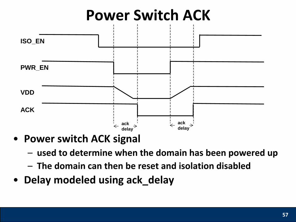
Power Switch ACK
• Power switch ACK signal – used to determine when the domain has been powered up
– The domain can then be reset and isolation disabled
• Delay modeled using ack_delay
57
ACK
PWR_EN
VDD
ISO_EN
ack
delay
ack
delay
Power Aware Coverage • Functional coverage
– only addresses the design functionality without the effects of Power
• Power Aware coverage – needs to address the aspects of Power
• Coverage of System Power States – Power states that a system is designed for need to be
covered by the simulation vectors
• Coverage of Transitions – All legal transitions need to be covered
– Negative tests to cover illegal transitions ensure the system doesn’t behave undeterministically
58
Conclusion • Most of todays SOCs have Low Power. • Power Aware verification at all design stages (RTL,
Implemented netlist and PG netlist) is a must to ensure silicon success.
• Power Aware Static verification is required to catch basic power related bugs quickly without having any test scenarios.
• Power Aware simulation is required to catch control sequence related bugs using power aware testbench.
• Power Aware coverage ensures that all Power related scenarios have been covered.
59