low power flow(upf)
DESCRIPTION
presentation on upfTRANSCRIPT

Design & Verificationof
Low Power SoCs

Need for Low Power ● High power density causes cooling and packaging challenges● Cost of cooling solution is comparable to the cost of system.● Reliability issues – mean time to failure decreases exponentially with temperature● Timing degradation and leakage current issues are more pronounced● Lower the feature size, more prominent is the leakage current. ● It is nearly as large as dynamic current.● Potential failure to meet the expected life of a battery
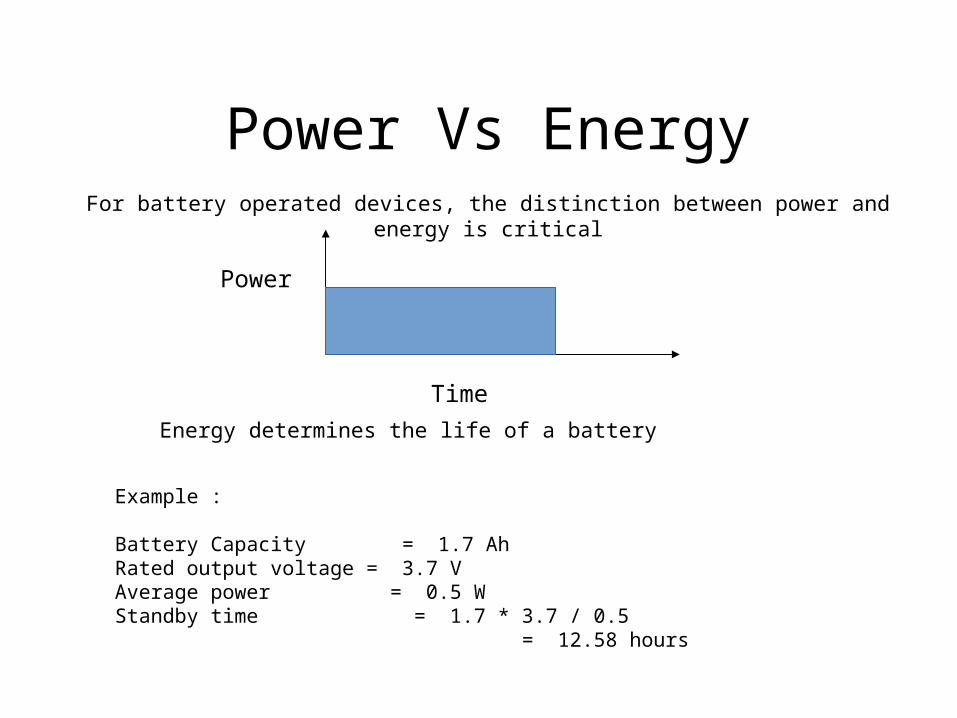
Power Vs EnergyFor battery operated devices, the distinction between power and energy is critical
Power
Time
Energy determines the life of a battery
Example :
Battery Capacity = 1.7 AhRated output voltage = 3.7 VAverage power = 0.5 W Standby time = 1.7 * 3.7 / 0.5 = 12.58 hours

Energy
• Batteries have finite amounts of energy stored in them• Running fast and then idling wastes energy
Time
Voltage
Reduce Voltage
Reduce Voltage
ReduceVoltage
ReduceVoltage
Reduce Voltage
Reduce Voltage
Task 1 Task 2 Task 3Idle
Energy
EnergySaved
Energy
Run Task Slow as Possible
Run Task Slow as Possible
Run Task in Available Time
Run Task in Available Time
Only need to run just fast enough to meet the application deadlinesOnly need to run just fast enough to meet the application deadlines

Components of PowerPower
Static Dynamic
Switching Internal
ISUB IGATE IGIDL IREV ICROWBAR ICHARGING
ISUB = Sub-threshold leakageIGATE = Gate leakageIGIDL = Gate Induced Drain LeakageIREV = Reverse bias junction leakage

Trends In Power Dissipation
• Static power dissipation can no longer be ignored– It became significant at 90nm and dominant at 65nm
• Leakage currents are rising fast– Must be controlled by circuit design and optimization tools
Slide 97 (of 118)

Slide 106 (of 118)
Low Power Challenges:• Manage power in all modes in which a design operates
– Dynamic power during device operation including active leakage– Static power dissipation during standby
• Maintain device performance while minimizing power consumption– Meet most aggressive performance targets while minimizing power– Aggressive power optimization when running at reduced performance levels– Minimize impact to performance by employing aggressive low power techniques– Employ a number of low power techniques in a single processor implementation
• Aggressive techniques for power management– Dynamic power minimized through OS directed performance scaling– Dynamic power minimized through use of Multi-Vt and Multi-L libraries– Standby power minimized through power gating with state retention– Additional standby power savings through use of threshold scaling (bias)

A UPF Example

Power management Structures: The Data Objects
• Power Domain– The collection of design objects
that share common power attributes
• Power States– Controlled by Switches– Memories may require
Retention– States may require sequencing
info– States will effect simulation
• Relations & Connections between Domains
– Level shifters– Isolation logic– “Gas Stations”
alternate supply• Identify elements• Manage• Implement• Analyze• Reuse

Divide the design into different power domains
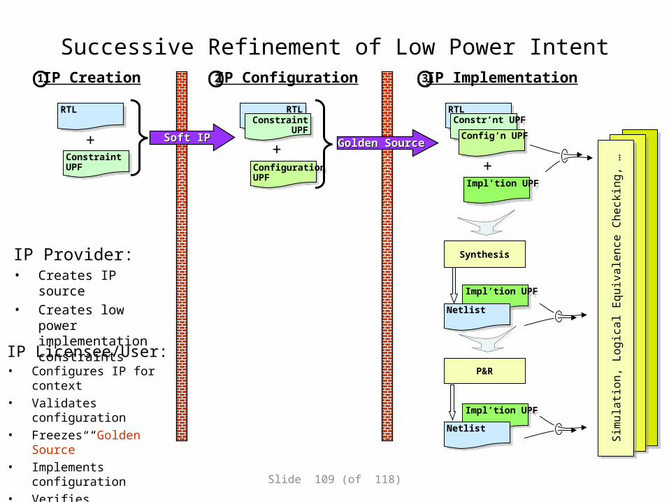
Successive Refinement of Low Power Intent
IP Provider:• Creates IP source• Creates low power
implementation constraints
Slide 109 (of 118)
IP Licensee/User:• Configures IP for context• Validates configuration• Freezes “Golden Source” • Implements configuration• Verifies implementation against
“Golden Source”
RTL
RTL
ConstraintUPF
ConstraintUPF
+
RTL
RTL Constraint
UPFConstraint
UPF
ConfigurationUPF
ConfigurationUPF
+
RTL
RTL Constr’nt UPFConstr’nt UPF
Config’n UPFConfig’n UPF
Impl’tion UPFImpl’tion UPF
+
Impl’tion UPFImpl’tion UPF
Impl’tion UPFImpl’tion UPF Sim
ula
tion
, L
og
ica
l Eq
uiv
ale
nce
Ch
eck
ing
, …
Sim
ula
tion
, L
og
ica
l Eq
uiv
ale
nce
Ch
eck
ing
, …
NetlistNetlist
Synthesis
Netlist Netlist
P&R
Soft IPSoft IP Golden SourceGolden Source
IP Creation1 IP Configuration2 IP Implementation3
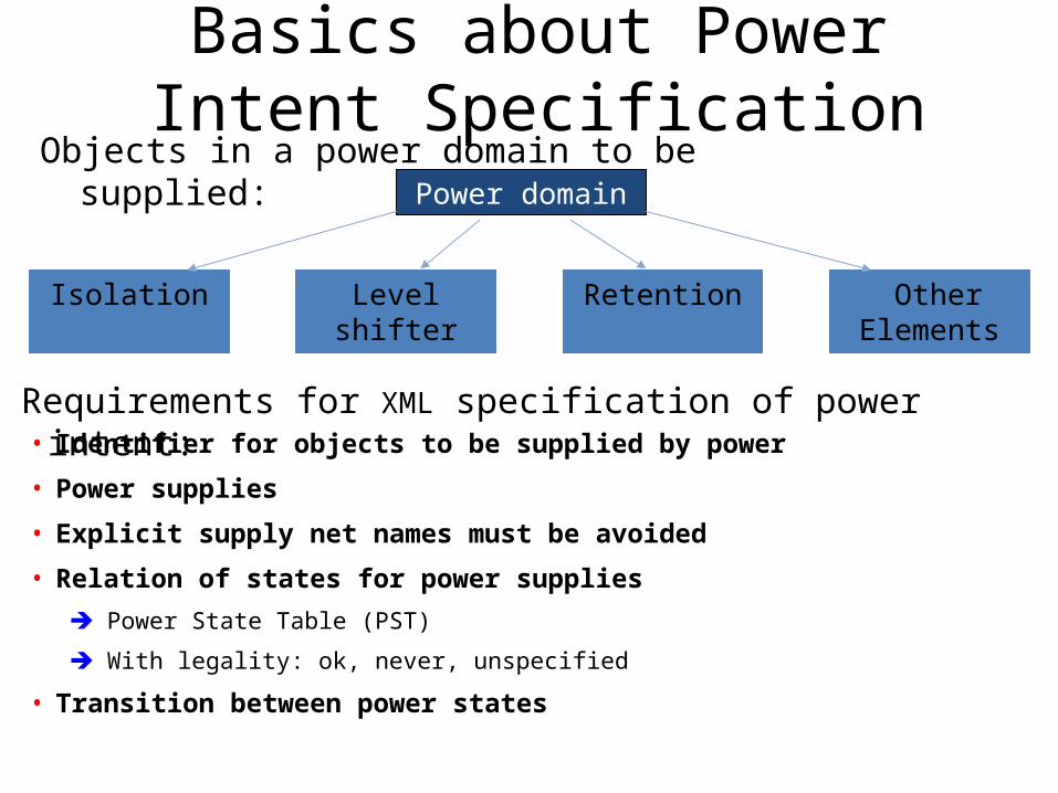
Basics about Power Intent Specification
Objects in a power domain to be supplied:Power domain
Isolation Level shifter
Retention Other Elements
Requirements for XML specification of power intent:• Identifier for objects to be supplied by power
• Power supplies
• Explicit supply net names must be avoided
• Relation of states for power supplies
Power State Table (PST)
With legality: ok, never, unspecified
• Transition between power states
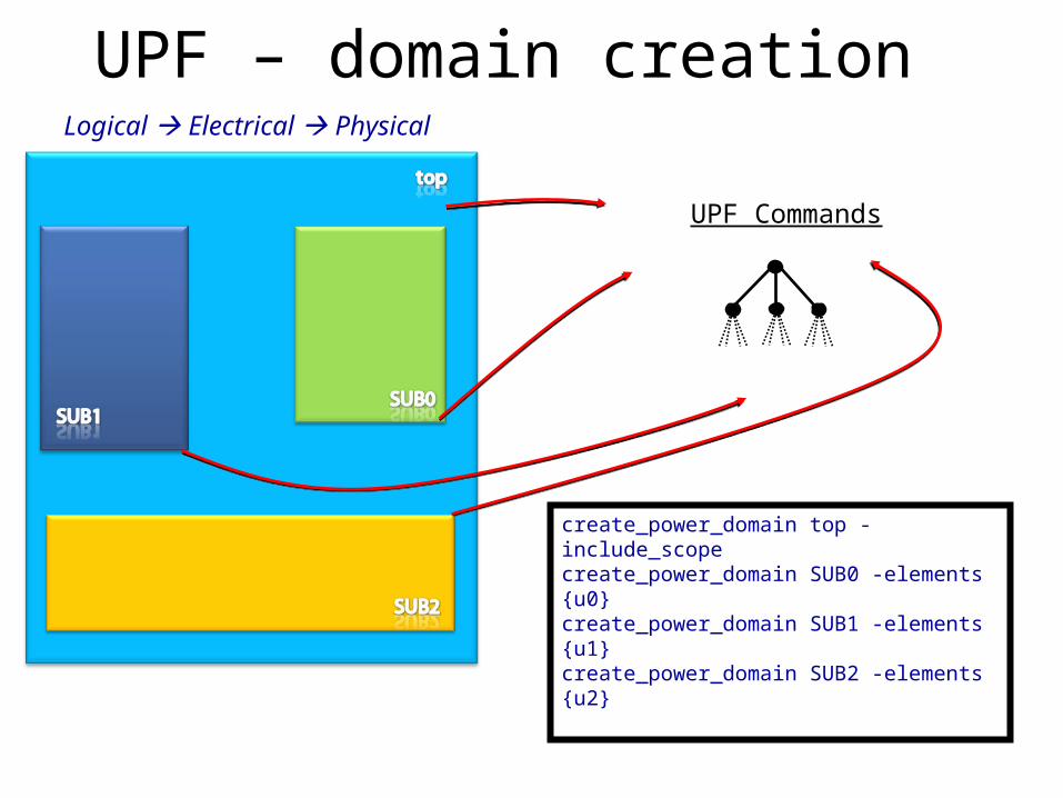
UPF – domain creation
Diagram from Andrew
Domain1constant
create_power_domain top -include_scopecreate_power_domain SUB0 -elements {u0}create_power_domain SUB1 -elements {u1}create_power_domain SUB2 -elements {u2}
Logical Electrical Physical
u0 u1 u2
UPF Commands

UPF – supply network creation
#Supply net creation for domain topcreate_supply_net VDD -domain topcreate_supply_net VDD_SUB1 -domain topcreate_supply_net VDD_SUB2 -domain topcreate_supply_net GND -domain top
#Supply net creation for domain SUB0create_supply_net VDD -domain SUB0 -reusecreate_supply_net VDD_SUB0_SW -domain SUB0create_supply_net GND -domain SUB0 -reuse
#Supply net creation for domain SUB1create_supply_net VDD_SUB1 -domain SUB1 -reusecreate_supply_net GND -domain SUB1 -reuse
#Supply net creation for domain SUB2create_supply_net VDD_SUB2 -domain SUB2 -reusecreate_supply_net GND -domain SUB2 -reuse
Diagram from Andrew
Domain1constant
UPF Commands
Logical Electrical Physical

UPF – supply network creation cont…
create_supply_port VDD -domain topcreate_supply_port VDD_SUB1 -domain topcreate_supply_port GND -domain topcreate_supply_port VDD_SUB2 -domain top
connect supply_net VDD –ports VDDconnect supply_net VDD_SUB1 –ports VDD_SUB1connect supply_net VDD_SUB2 –ports VDD_SUB2connect supply_net GND –ports GND
set_domain_supply_net top \-primary_power_net VDD \-primary_ground_net GND
set_domain_supply_net SUB0 \-primary_power_net VDD_SUB0_SW \-primary_ground_net GND
set_domain_supply_net SUB1 \-primary_power_net VDD_SUB1 \-primary_ground_net GND
set_domain_supply_net SUB2 \-primary_power_net VDD_SUB2 \-primary_ground_net GND
UPF Commands
Diagram from Andrew
Domain1constant

UPF – levelshifter strategy
Diagram from Andrew
Domain1constant
Level shifter considerations
• Pick a power domain or a set of elements
• Select input ports, output ports, or both
• Tolerate a voltage difference threshold
• UP shift or down SHIFT rule
• Location (self, parent, sibling, fanout, auto)
• Insert or not insert

UPF – levelshifter strategy
Diagram from Andrew
Domain1constant
UPF Commands
set_level_shifter SUB1_to_TOP \ -domain SUB1 \ -applies_to outputs \ -rule low_to_high \ -location parent
set_level_shifter TOP_to_SUB1 \ -domain SUB1 \ -applies_to inputs \ -rule high_to_low \ -location self
set_level_shifter SUB2_to_TOP \ -domain SUB2 \ -applies_to outputs \ -rule low_to_high \ -location parent
set_level_shifter TOP_to_SUB2 \ -domain SUB2 \ -applies_to inputs \ -rule high_to_low \ -location self

UPF – isolation cell strategy
UPF Commands
set_isolation ISO_STRAT \ -domain SUB0 \ -isolation_power_net VDD \ -isolation_ground_net GND \ -clamp_value 0
set_isolation_control ISO_STRAT \ -domain SUB0 \ -isolation_signal reg_out[25] \ -isolation_sense high \ -location parent
Diagram from Andrew
Domain1constant
ISO
VDD GND
PM ctrl logic

UPF - retention cell strategy
Diagram from Andrew
Domain1constant
ISO
VDD GND
PM ctrl logic
set_retention key_desIn \ -domain SUB0 \ -retention_power_net VDD \ -elements {u0/uk/ret_key_sel u0/ret_des_key_r \ u0/ret_desIn_r}
set_retention_control key_desIn \ -domain SUB0 \ -save_signal {key_b_r_reg[16][27]/pin:Q high} \ -restore_signal {key_b_r_reg[16][26]/pin:Q low}
UPF Commands

UPF - switch cell creation
create_power_switch SUB0_SW \ -domain SUB0 \ -input_supply_port {TVDD VDD} \ -output_supply_port {VDD VDD_SUB0_SW} \ -control_port {NSLEEPIN1 SE_ME_on_1 } \ -control_port {NSLEEPIN2 SE_ME_on_2 } \ -ack_port {NSLEEPOUT1 SE_ME_on_ack_1} \ -ack_port {NSLEEPOUT2 SE_ME_on_ack_2} \ -on_state {SW_on TVDD {NSLEEPIN2 & NSLEEPIN1} } \ -off_state {SW_off {!NSLEEPIN2 & !NSLEEPIN1}}
NSLEEPIN1
NSLEEPIN2
NSLEEPOUT1
NSLEEPINOUT2
TVDD
VDD
VDD
VDD_SUB0_SW
Diagram from Andrew
Domain1constant
ISO
VDD GND
PM ctrl logic
UPF Commands

UPF – power states
Diagram from Andrew
Domain1constant
ISO
VDD GND
PM ctrl logic
• A power state table defines the legal combinations of states for different domains
• The create_pst command creates a PST, using a specific order of supply nets during operation of the design
• Each row defines a valid combination of supply states
• Power states enable optimization and verification• Infer of verify level shifters and
isolation gates

UPF – power states
create_pst PM_pst –supplies\ { VDD u0/VDD_SUB0_SW VDD_SUB1 VDD_SUB2 }
add_pst_state pst0 –pst PM_pst –state \{ VDD_N SW_on SUB1_H SUB2_H}
add_pst_state pst1 –pst PM_pst –state \{ VDD_N SW_off SUB1_L SUB2_L}
VDD VDD_SUB0_SW
VDD_SUB1
VDD_SUB2
pst0 VDD_N SW_on SUB1_H SUB1_H
ps1 VDD_N SW_off SUB1_L SUB1_L
Diagram from Andrew
Domain1constant
ISO
VDD GND
PM ctrl logic
UPF Commands

Defining a Power State• Same command for both supply sets and domains
– add_power_state object_name-state state_name -supply_expr {boolean_expr} -logic_expr {boolean_expr} [-simstate simstate] -legal | -illegal -update
• Can be refined (-update) over time as design evolves– -supply_expr is the golden specification of the power state – used by synthesis and LEC– -logic_expr initial, approximation of the power state definition (in the absence of a –
supply_expr)• -logic_expr becomes an assertion check when –supply_expr is specified• -supply_expr and –logic_expr state definitions can be refined
– supply_expr’ = old_supply_expr && new_supply_subexpr
• Legality– The default for a user-defined power state is legal
• Specify –illegal to override default; -legal to be explicit
– By default, undefined power states are illegal• Override default legality of undefined power states for an object:
add_power_state my_power_domain -legal

Power Portion of Robust InterfaceDesigning within a context
UPF Commands: mod_ifCreate_power_domain mod_PD
-include_scopeCreate_power_domain GCreate_power_domain BSet_port_attributes
-ports {G1, G2}-supply_set G.primary
Set_port_attributes-ports {B1, B2, B3}-supply_set B.primary
<Set_port_attributes-ports {M1, M2}-supply_set mod_pd.primary>
mod_details:Create_power_domain G -update
-elements {Green}Create_power_domain B-update
-elements {Blue}
mod
Green
Blue
Supply sets and set_port_attributes
G1 G2 B1 B2 B3 M1 M2

Use Components in an DesignUPF Commands: topcreate_power_domain top_PD
-include_scopecreate_power_domain pd_G
-elements {Y}create_power_domain pd_B
-elements {Z}set base set_scopeforeach {el} {I1 I2 I3} {
set_scope $base/$elload_upf “mod_if.upf”
}set_scope $base
create_composite_domain topc_PD –subdomains {top_PD U1/mod_PD U2/mod_PD U3/mod_PD}
create_composite_domain pdc_G –subdomains {pd_G U1/G U2/G U3/G}
create_composite_domain pdc_B –subdomains {pd_B U1/B U2/B U3/B}
mod
Green
Blue
G1 G2 B1 B2 B3 M1 M2
Y
mod
Green
Blue
G1 G2 B1 B2 B3 M1 M2
mod
Green
Blue
G1 G2 B1 B2 B3 M1 M2

Power Tasks on both sides of the Abstraction
Front end:• Functional specification• Checking the specification
– Corruption recognized– Srikanth will provide more detail
• Specify allowed and forbidden power states and transitions
– Ensure forbidden states and transitions never present
– Electrical safety
• Inserts corruption based on power• Specify and validate Isolation
Back End:• Structural specification• Correlation to structural
– No new corruption
• Electrical protection (level shifting) for all possible states (or specified requirements)
– Implementation is conservative compared to specification
• Logical protection - Isolation• Structural checks – all supplies that
affect the behavior are accounted for in the front end.
Simulate and Implement same the Design

Verification of Power Managed Designs

Range of Voltage-Control Techniques
0.9V0.9V1.0V1.0V
1.2V1.2V
0.6V
0.9V0.9V1.0V1.0V
1.2V1.2V
OFF
0.9V0.9V1.0V1.0V
1.2V1.2V
Multi-Vdd (MV) MTCMOS power gating (shut down)
Low-VDD Standby
A Z
VDDB
VSSB
Variable VTH
(Back Bias – P/N)
Dynamic or Adaptive Voltage Frequency Scaling(DVS, DVFS, AVS, AVFS)
0.9V0.9V1.0V1.0V
1.2V1.2V
RET
Power gating with State Retention
0.9-1.2V0.9-1.2VPWRCTRL
PWRCTRL
1.0V1.0V 0.9V0.9V

Power Management increases verification complexity enormously
Phone Call PDA Standby
Tx/Rx inNormalMode
CPU in Normal Mode
Audio in NormalMode
Display in Normal Mode
Video in Normal Mode
V1
V2
V3
Display in Standby
Tx/Rx inStandby
Display in HP Mode
CPU in HP ModeCPU in Standby
PMU
Level Shifters Isolation Cells
Multiple power states, transitions and sequences must be verified
Verification must now understand voltage values
Correct implementation of LP specific design elements must happen
Display in OFF Mode
with Power Switches
Audio in OFF Mode
with Power Switches
Video in OFF Mode
withPower Switches

Power Management brings new bug types!
– Isolation/Level Shifting Bugs– Control Sequencing bugs– Retention scheme/control errors– Retention selection errors– Electrical Problems like memory corruption– Power Sequencing/Voltage Scheduling errors– Hardware-Software deadlock– Power Gating collapse/dysfunction– Power On Reset/bring up problems– Thermal runaway/ Overheating
These are not traditional functional bugs!

Bug Classification• Structural Errors
– Missing Isolation, Level Shifters– Devices in wrong domains– Wrong Rail connections
• Control Errors– Mistimed Control signals– Incorrect control activation sequence– Incorrect gating/ungating in off/low power states
• Architectural Errors– Incorrect partitions, policies– Incorrect scheduling of resources

Structural Errors
Domain 1
ON(1.2V)/OFF
Domain 1
ON(1.2V)/OFF Domain 3
ON (1.2V)
Domain 3
ON (1.2V)Domain 2
0.9-1.2
Domain 2
0.9-1.2
PMIC/PMUPMIC/PMUISO-Enable
Isolation
Level Shifters
Structure needs to be checked constantlythrough out the implementation flow

Incorrect Isolation SequenceControl Error
Intended Behavior
1. Gate the clk
2. Assert iso to 0
3. Assert sleep to 0
Intended Behavior
1. Gate the clk
2. Assert iso to 0
3. Assert sleep to 0
Output HighZ based on sleep signal
X is observed due to incorrect iso timing
Registers initialized to X after power restoration
Actual Behavior
1. Gate the clk
2. Assert sleep to 0
3. Assert iso to 0
Actual Behavior
1. Gate the clk
2. Assert sleep to 0
3. Assert iso to 0
Control signal sequence error is
discovered due to X propagation

Voltage Scheduling ErrorControl/Architecture Error
Top
1.2V 0.9V
1.1V 0.8V
A[63:0]
Island 2Island 1
Logic Simulator cannot distinguish between voltage values - All treated as 1
1.2V1.1V
0.9V0.8V
Verification must be aware of the waveform nature of voltage
Need Level Shifter
1.2V1.1V
0.9V0.8V

Voltage-Aware Simulation is now necessary!
1 1 11
0.7 V 1.0 V
Traditional Simulators are not voltage aware
Traditional Simulators are not voltage aware
Voltage-Aware Simulators are Electrically Accurate
Voltage-Aware Simulators are Electrically Accurate
1 X X1
1.0 V 0.7 V
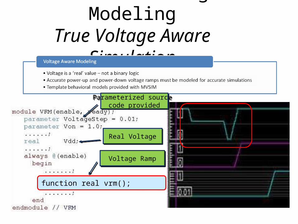
Accurate Voltage ModelingTrue Voltage Aware
Simulation
Real VoltageReal Voltage
Voltage RampVoltage Ramp
function real vrm();
Parameterized source code provided
Parameterized source code provided

The rise of Retention• State loss from Power Shut Off may not be OK
Performance hit with cache misses Or Latency impact for ‘Cold Start’
• Traditionally, Low Vdd Stby was used to retain state
• As Vtn, Vtp ->0, Vstby becomes impractical Retention flops: Shadow the main element with high Vt Cut off Vdd, but hold on to Shadow element power Restore from Shadow to main element after powerup
Many Flavors of Retention exist Languages don’t model them well!
Retention is a huge verification challenge

Retention stretches language semantics
Slide 67 (of 118)
• Retention : A balloon latch is used to retain state when power is turned off
• Wait, we lack semantics for shutdown, how do we deal with this?
always @ (posedge clk or negedge reset_n)if (!reset_n) q <= 0;else q <= d;
always @ (posedge clk or negedge reset_n or posedge save or posedge restore)if (!vdd) q <= 1’bx;else if (!reset_n) q <= 0;else if (save) q_s <= q;else if (restore) q <= q_s;else q <= d;Need to simulate
and verify this!
Retention is a huge verification challenge

Verifying Retention Complete power Sequence
CLK
ISO
CLK -EN
SAVE
PWR EN
RESTORE
VDD
PWR RDY
DisableClock
Save
EnableIsolation
DisablePower
RampVoltage
DisableReady
EnablePower
RampVoltage
EnableReady
Restore
DisableIsolation
EnableClock

Verifying Retention Corner Cases Can Be Tricky
SAVE
PWR GATED DMA
ACTUAL RESTORE
REG A aa ZX
REG B bb bbZ
EXPECTED RESTORE
X
PREMATURE RESTORE SIGNALPREMATURE RESTORE SIGNAL

Low Power Testbenches

Elements of a Low Power Testbench

Coding Guidelines• 1’b0 and 1’b1 – no single supply1 or supply0
– Use tie_hi_<name> or tie_lo_<name>
• Initial blocks don’t get retriggered again– Be careful with readmem and other initializations in on/off
• Asynch reset doesn’t get activated again – Could be design or testbench issue
• X-detection monitors can go crazy– Avoid stopping the test on “x” in an on/off block!
• Assertions need to account for off state!• Don’t use XMR force statements!• …

Redefining Coverage
CORE
AllOn ON CORE Domain1 Domain2
AllOff OFF OFF OFF
LP0 ON OFF OFF
LP1 ON OFF ON
LP2 ON ON OFF
AllOn ON ON ON
CORE (ON)
DOMAIN 2
ON/OFF
DOMAIN 2
ON/OFF
DOMAIN 1
ON/OFF
DOMAIN 1
ON/OFF
AllOff
AllOn
LP0 LP1
LP2
AllOn
Power Intent elements, Power States, Transitions and Sequences need a Coverage strategy

RTL Lines
VoltageIslands
Power States
RTL Assertions
Gate Level Assertions
6099 4 8 685 1891
• Absence of one leaf-level assertion will cause failure of design
• Source level assertions cannot be relied upon to ensure correct operation of design
Slide 79 (of 118)
PMUPMU
ON/OFF
PowerswitchPowerswitch
PS_ENABLE
Source assertions may not propagate to all leaves
Source assertions may not propagate to all leaves
Source Assertion:
When PS_ENABLE =1, ISO_ENABLE = 0
ISO_ENABLE
Source vs. Leaf level assertions

Low Power IntentAn IP Providers Perspective

Soft IP Provider’s Low Power Intent
A Soft IP provider need only declare four things:
1. The "atomic" power domains in the design• these can be merged but not split during implementation
2. The state that needs to be retained during shutdown• with out prescribing how retention is controlled
3. The signals that need isolating high/low• with out prescribing how isolation is controlled
4. The legal power states and sequencing between them• with out prescribing absolute voltages

Successive Refinement Example1. UPF Constraints
– IP provider needs to "identify" what is to be isolated with out prescribing how:set_isolation my_iso -domain my_pd \
-clamp_value 0
2. UPF Configuration– System Level simulation guy needs to configure the logical power controls with out
having to specify the power supplies:set_isolation -update my_iso -domain my_pd \
-isolation_signal CLAMP -isolation_sense high
3. UPF Implementation– Finally the details of power supplies are then added during implementation
set_isolation -update my_iso -domain my_pd \-isolation_power_net VDDG -location parent
Or specify it all at the same time:set_isolation my_iso -domain my_pd \
-clamp_value 0 \-isolation_signal CLAMP -isolation_sense high \
-isolation_power_net VDDG -location parent
Slide 110 (of 118)

Controlling Clocks, Resets and Power
• Can use UPF inferred clamps to stop clocks and assert reset– Needs care to avoid timing issues
• Better to use handshaking controlled by a simple state machine– Facilitates design reuse and technology portability
Slide 113 (of 118)
Power GatingController
State Machine
Synchronizers
VDD ( “always on”)
“WAKE- UP” REQ
CLOCK_REQ
CLAMP _REQ
N_RETAIN_REQ
N_RESET_REQ
N_START _REQ
N_ PWR_REQ
CLOCK ACK
( CLAMP_ACK)
(N_RETAIN_ACK)
(N_RESET_ACK)
N_ START_ACK
N_ PWR_ACK
“SLEEP” REQ
SYSTEM CLOCK
VSS
nPWR
VDD (“always on”)
VDD_SW
-Power GatedRegion “PD”
nCLAMP
nRESET
CLOCK ENABLE

Sequencing Clocks, Resets and PowerPower down sequence:
1. Stop the clocks2. Apply isolation3. Optionally save state4. Assert reset5. Remove power
Power up sequence:1. Apply power2. Remove reset3. Optionally restore state4. Remove isolation5. Start the clocks
Slide 114 (of 118)
CLOCK
N_CLAMP
N_RESET
SAVE
RESTORE
N_PWR

A Few “Best Practices”…• Avoid non-contiguous power domains
– Can lead to unwanted isolation cells– If in doubt, align power domains with logic hierarchy
• Avoid using clock gating on both edges of the clock– Need for specialised ICGs may limit choice of implementation libraries
• Avoid partial retention within a power domain– Unless the IP has been explicitly designed to support it.– User defined partial state retention will require complete re-
verification – No support for “set_retention –no retention” in UPF-1.0
• Ensure that every power domain’s clocks and resets can be controlled externally Slide 115 (of 118)
A1 A2
Top
B2B1 B4B3

Conclusion:• Power dissipation is the #1 limiter of design performance
– Can be mitigated with advanced circuit design and optimization tools
• Power management is a system problem– Power management strategy must be carefully considered from architecture to silicon
• Need to ease adoption of advanced low power techniques– Develop low power IP, tools & techniques (ARM’s IEM & PMK)
• UPF enables portability of low power intent– Provides ability to to compare and contrast a variety of implemention strategies– Portable across EDA tools and supported by commercial low power libraries– Low power overlay to existing processor IP from ARM
Slide 116 (of 118)
Transistors (and silicon) are free. Power is the only real limiter.Optimizing for frequency and/or area may achieve neither.
Pat Gelsinger, Intel (DAC2004 Keynote)
Transistors (and silicon) are free. Power is the only real limiter.Optimizing for frequency and/or area may achieve neither.
Pat Gelsinger, Intel (DAC2004 Keynote)

References
Accellera http://www.lpmm-book.org

Thank You!