fan switch and limit switch information
DESCRIPTION
Fan Switch and Limit Switch Information. FAN Switch. Fan Switch. 1.The fan switch controls the motor for heating. 2.The fan switch contacts are NO. 3.It closes on a rise in temperature. - PowerPoint PPT PresentationTRANSCRIPT
Fan Switch
and
Limit Switch
Information
FAN
Switch
Fan Switch
1.The fan switch controls the motor for heating.
2.The fan switch contacts are NO.
3.It closes on a rise in temperature.
4.It is physically located in a location on the furnace
where it will ‘sense’ the heat from the heat exchanger.
5.It has a cut-in temperature setting, and this is the
temperature which will make the contacts close and
the fan will operate.
Fan Switch
6.It has a cut-out temperature setting and this is the
temperature which will open the contacts and the fan
will stop.
7.Some fan switches have adjustable CI and CO
settings. Some have fixed CI and CO settings.
Fan Switch
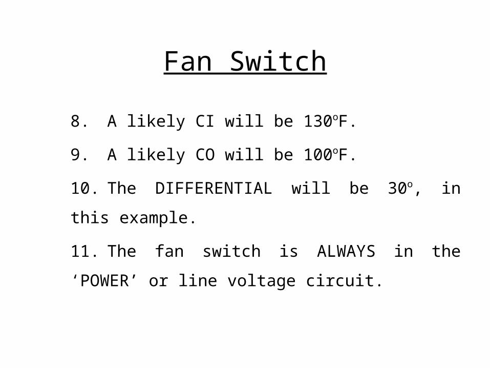
8.A likely CI will be 130oF.
9.A likely CO will be 100oF.
10. The DIFFERENTIAL will be 30o, in this example.
11. The fan switch is ALWAYS in the ‘POWER’ or
line voltage circuit.
This presentation will continue with the
fan switch that was used with ‘older’ gas
furnaces and is used on both old and new
oil furnaces.
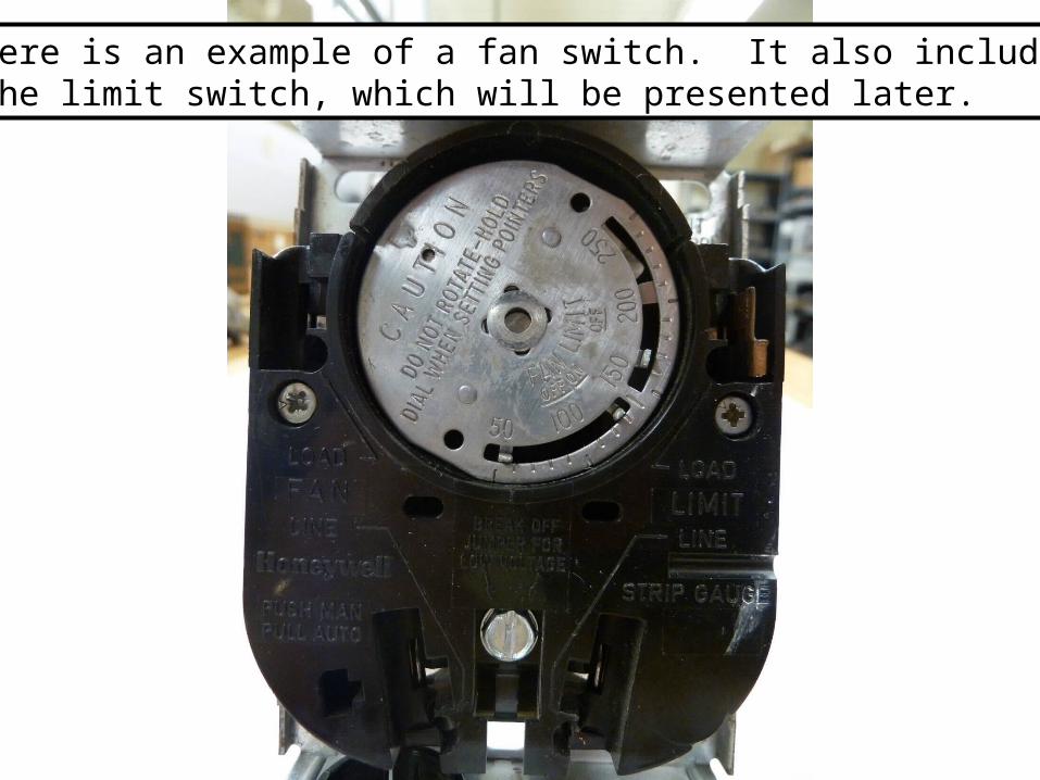
Here is an example of a fan switch. It also includesthe limit switch, which will be presented later.
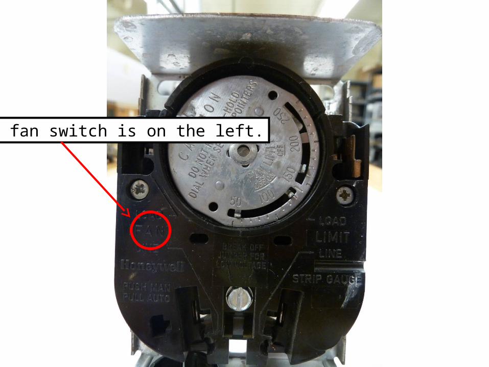
The fan switch is on the left.
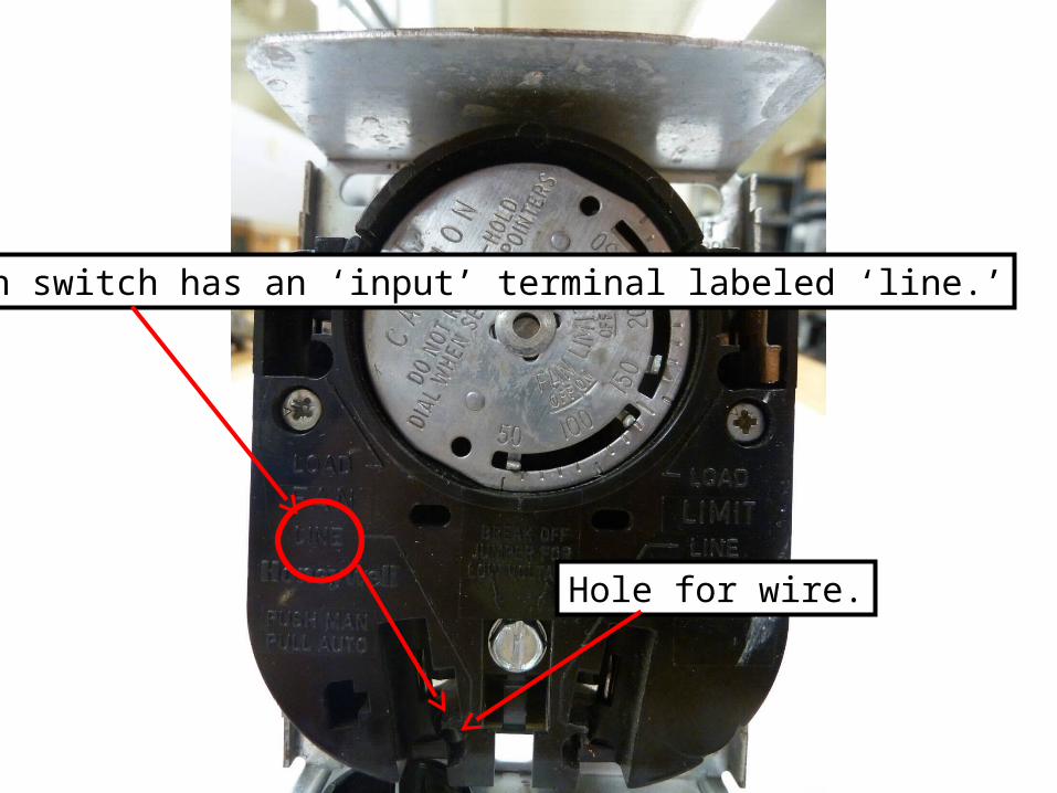
The fan switch has an ‘input’ terminal labeled ‘line.’
Hole for wire.
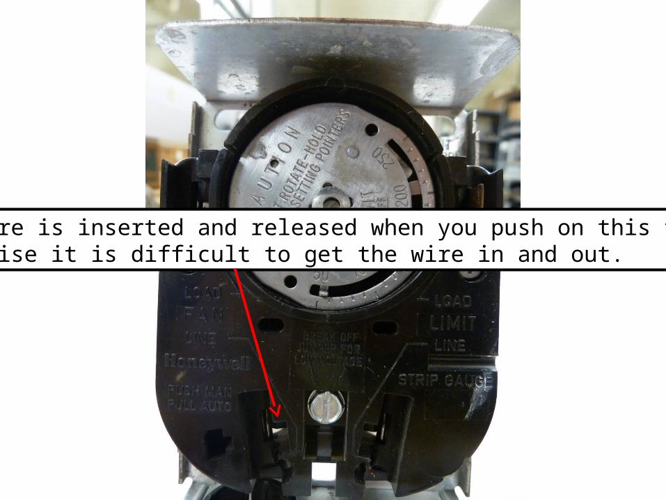
The wire is inserted and released when you push on this tab. Otherwise it is difficult to get the wire in and out.
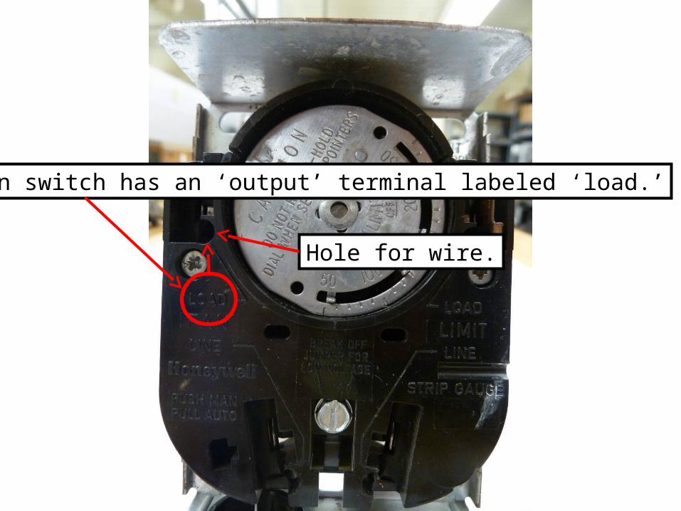
The fan switch has an ‘output’ terminal labeled ‘load.’
Hole for wire.
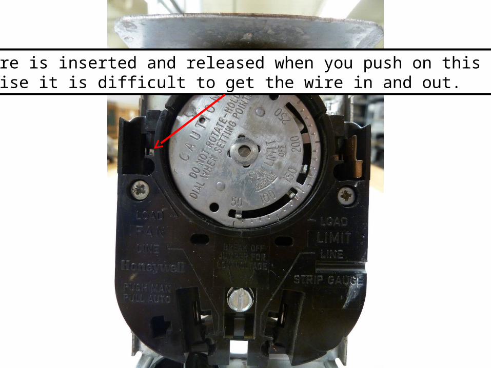
The wire is inserted and released when you push on this tab. Otherwise it is difficult to get the wire in and out.
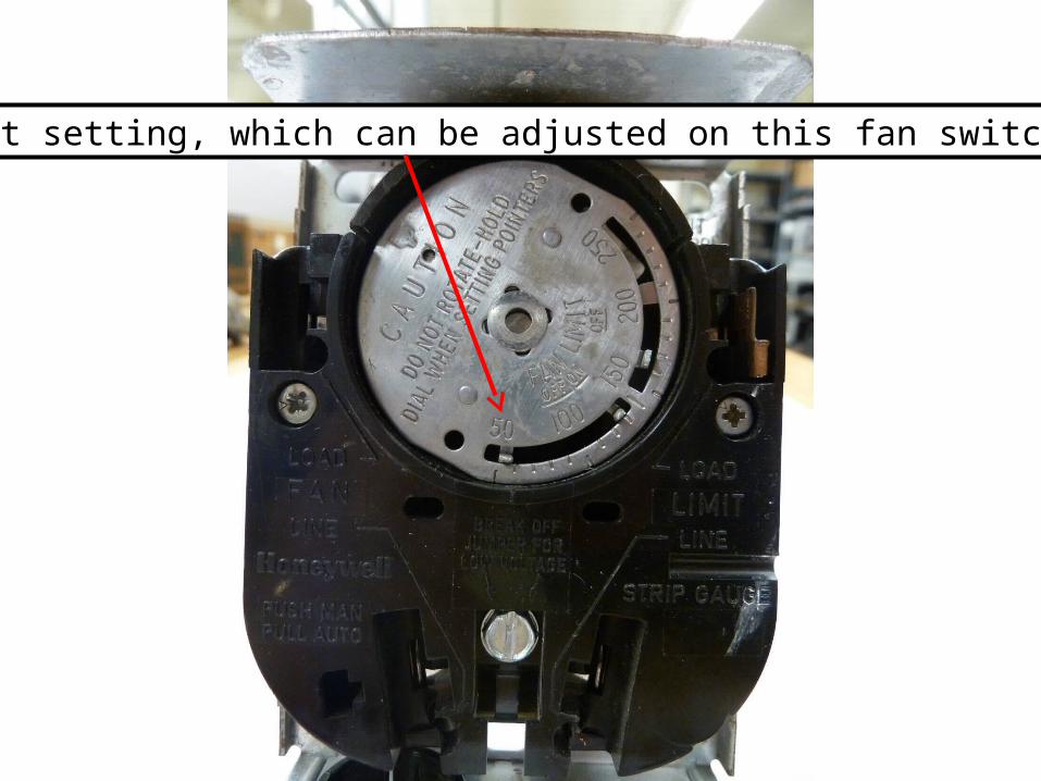
Cut-out setting, which can be adjusted on this fan switch.
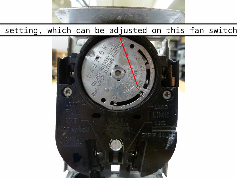
Cut-in setting, which can be adjusted on this fan switch.

Indicator mark on plastic housing to note thetemperature of the fan or limit switch.
Sometimes the fan switch will have a small
electric heater within its housing. This is called
a ‘fan assist’ heater. The heater will be
energized at the same time there is a call for
heat and the fan contacts, which are heat
dependent, will either close based on the
physical heat from the furnace heat exchanger,
or from the physical heat of this heater.
There are two applications for this heater.
1. Some manufacturers use this method to
bring the fan on ‘sooner’ than it would, based
on the physical heat from the heat exchanger.
This is done to raise the efficiency rating of
the furnace.
2. This method is used to keep the fan
operating in a down-flow furnace application. The fan
is on top of the furnace heat exchanger and when the
fan comes on, the heat rising up the furnace will be
blown down and away from the fan switch. Since it
is dependent on the heat from the heat
exchanger, it will cool off and stop the fan. Then
the cycle will start all over again and the fan will just
‘short cycle.’
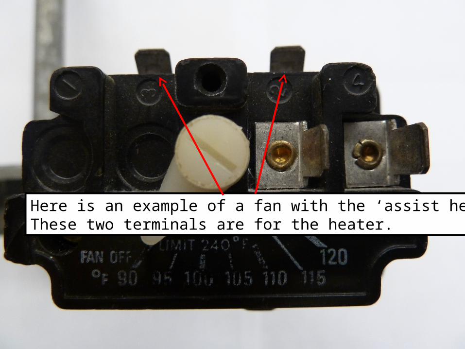
Here is an example of a fan with the ‘assist heater.’These two terminals are for the heater.
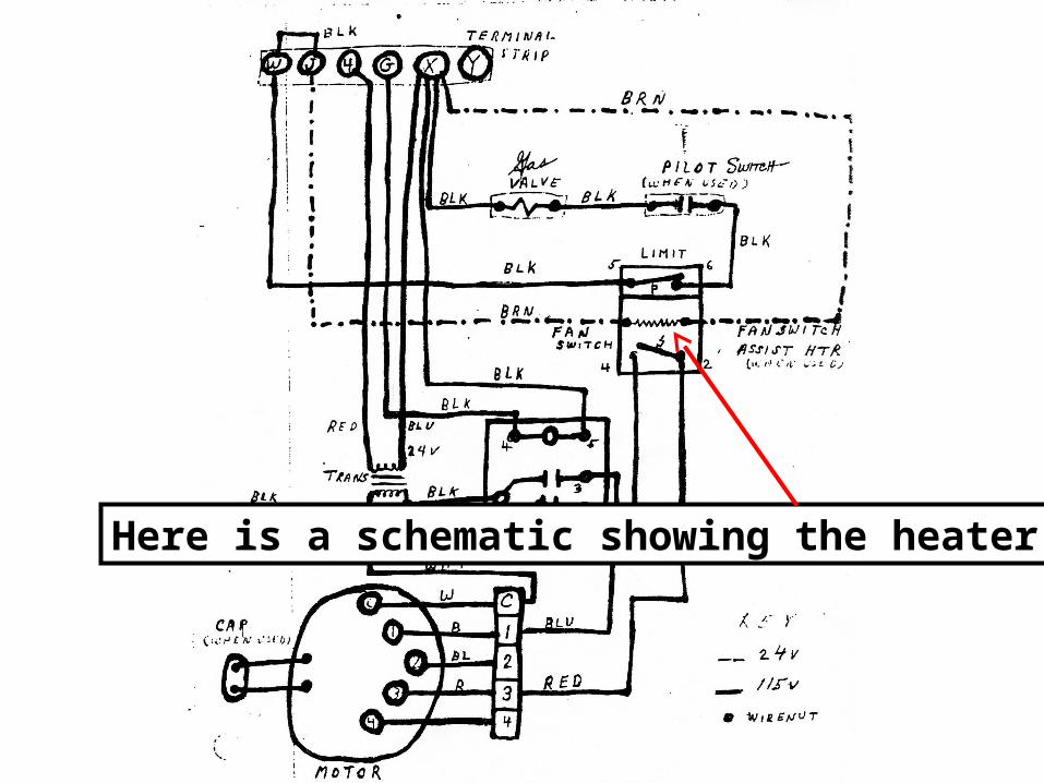
Here is a schematic showing the heater.
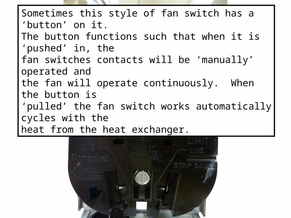
Sometimes this style of fan switch has a ‘button’ on it.The button functions such that when it is ‘pushed’ in, the fan switches contacts will be ‘manually’ operated and the fan will operate continuously. When the button is ‘pulled’ the fan switch works automatically cycles with the heat from the heat exchanger.
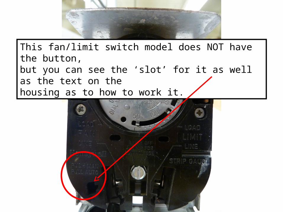
This fan/limit switch model does NOT have the button,but you can see the ‘slot’ for it as well as the text on the housing as to how to work it.

LIMIT
Switch
Limit Switch
1.The limit has NC contacts.
2.The limit is used to provide safety in the event the
temperature of the equipment should exceed a safe
operating level.
3.The limit may be wired in either the POWER (line
voltage) circuit or the CONTROL (low voltage) circuit.
Limit Switch
4.The limit has a cut-out that is usually around:
a. 200oF for barometric draft furnaces
b. 180oF for high efficiency furnaces
c. or whatever the manufacturer specifies
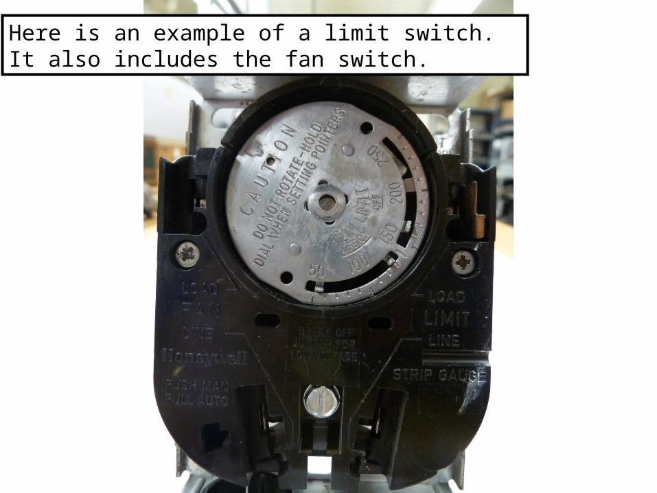
Here is an example of a limit switch. It also includes the fan switch.
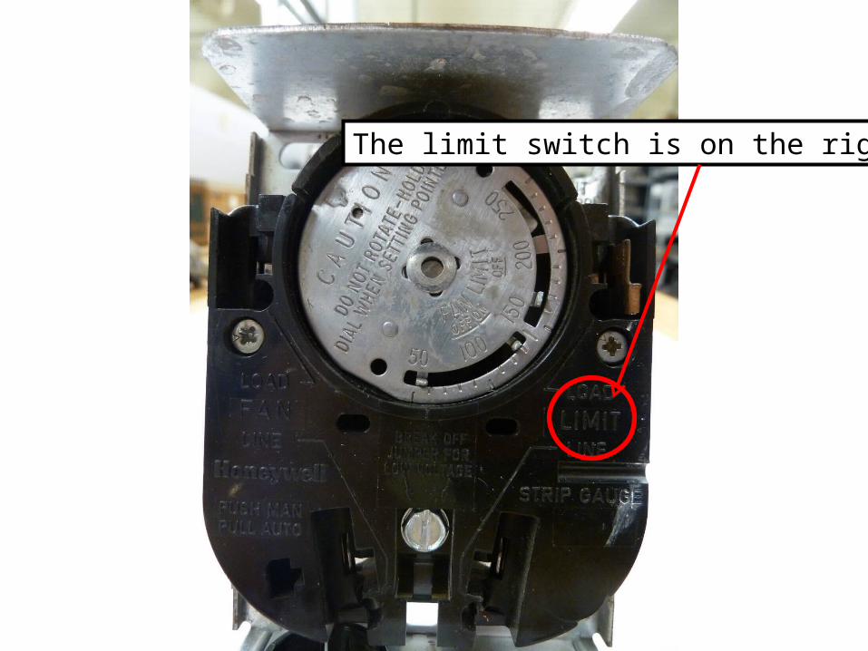
The limit switch is on the right.
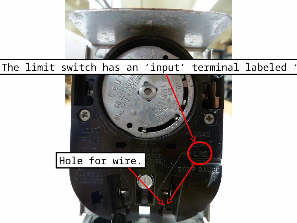
The limit switch has an ‘input’ terminal labeled ‘line.’
Hole for wire.
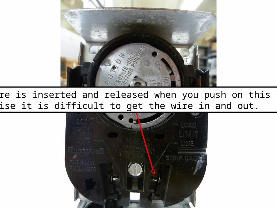
The wire is inserted and released when you push on this tab. Otherwise it is difficult to get the wire in and out.
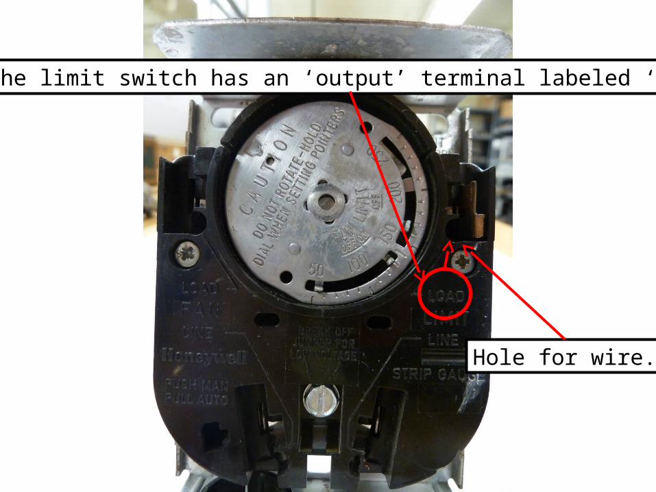
The limit switch has an ‘output’ terminal labeled ‘load.’
Hole for wire.
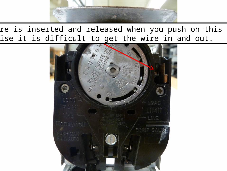
The wire is inserted and released when you push on this tab. Otherwise it is difficult to get the wire in and out.
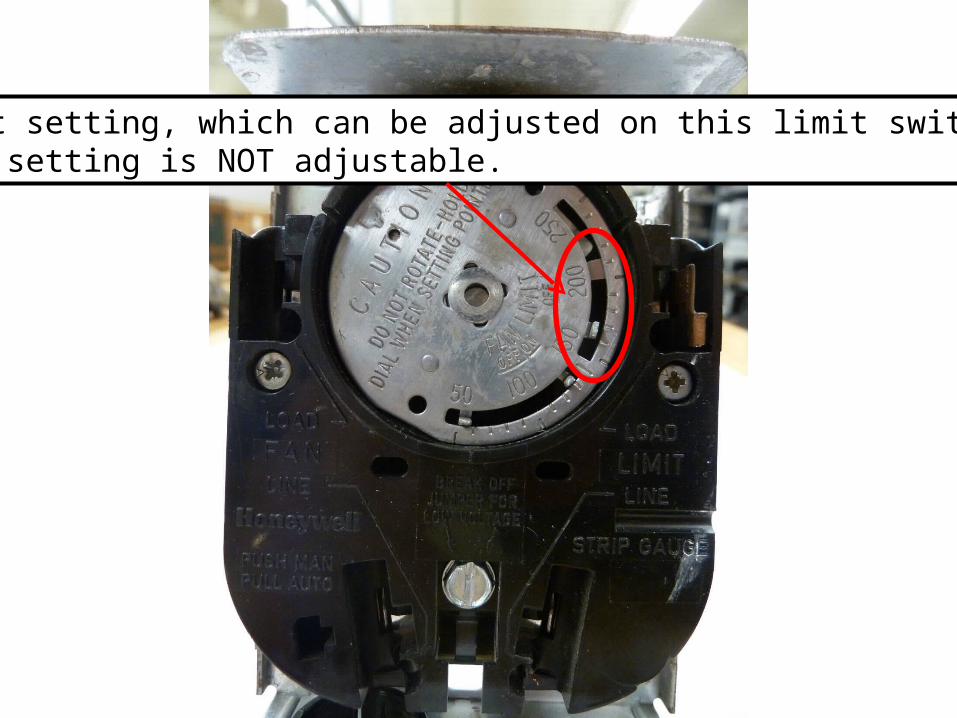
Cut-out setting, which can be adjusted on this limit switch.Cut-in setting is NOT adjustable.
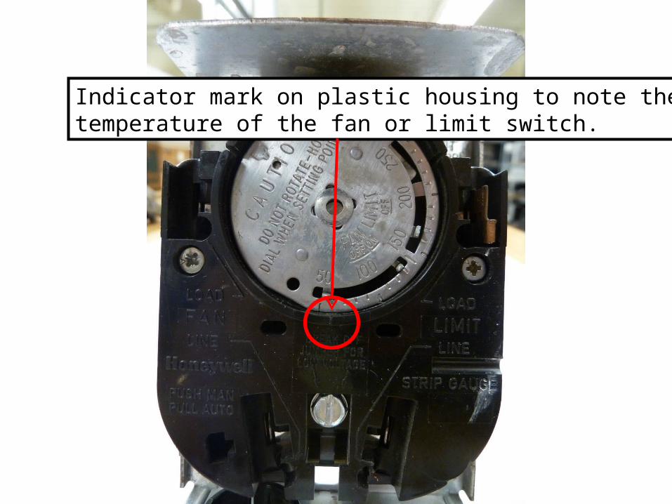
Indicator mark on plastic housing to note thetemperature of the fan or limit switch.
FAN and LIMIT
The fan and limit switches may be separate components or
they may be part of the same housing as shown on the
next slide. In this situation the components are called a
‘combination fan/limit switch.’
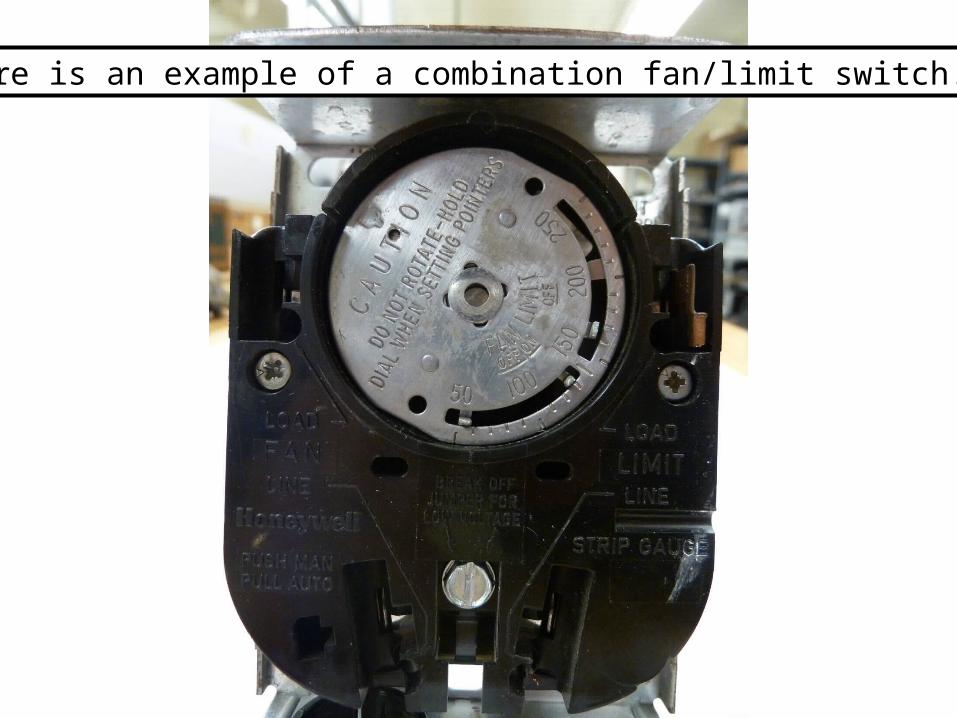
Here is an example of a combination fan/limit switch.
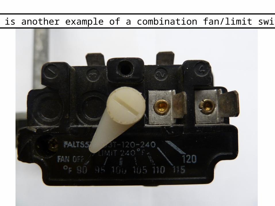
Here is another example of a combination fan/limit switch.
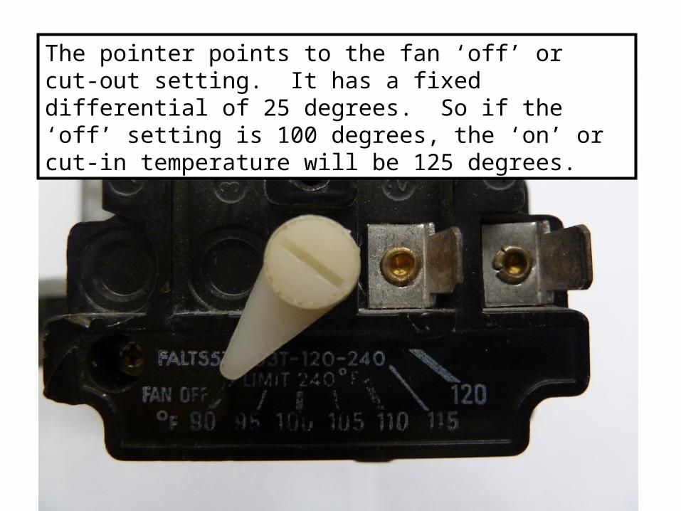
The pointer points to the fan ‘off’ or cut-out setting. It has a fixed differential of 25 degrees. So if the ‘off’ setting is 100 degrees, the ‘on’ or cut-in temperature will be 125 degrees.
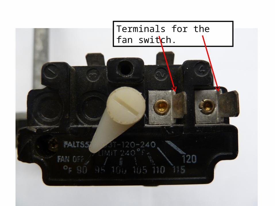
Terminals for the fan switch.
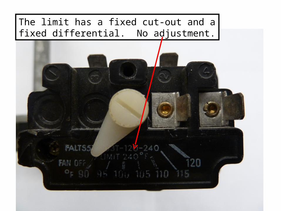
The limit has a fixed cut-out and a fixed differential. No adjustment.
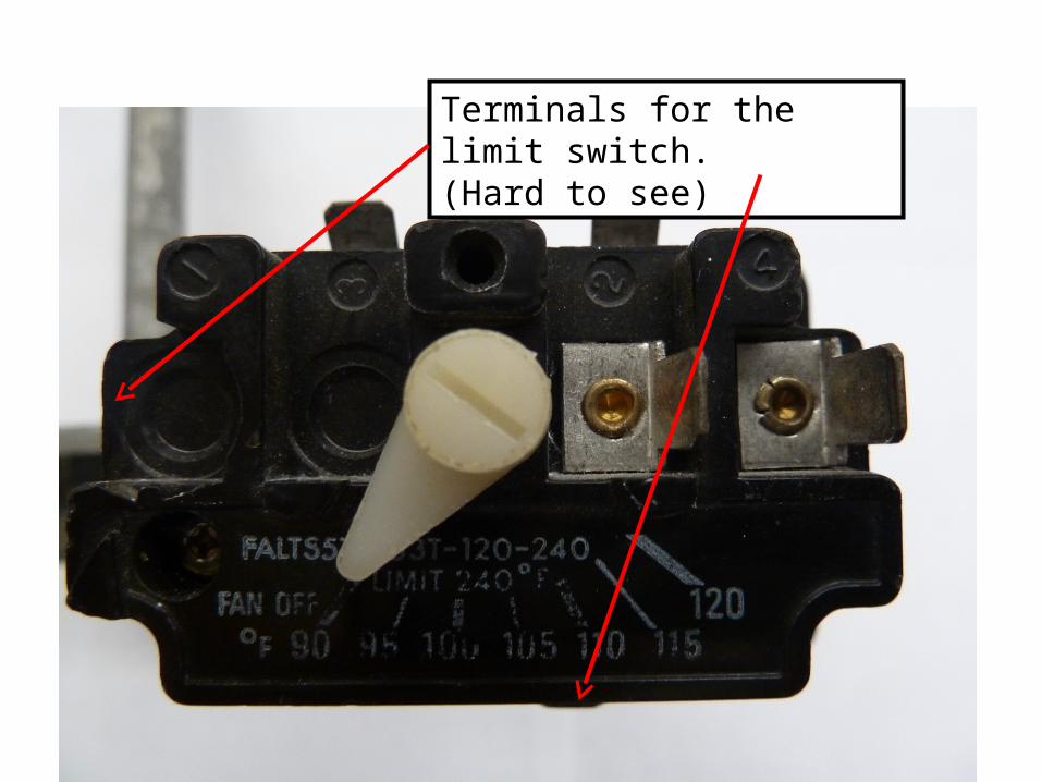
Terminals for the limit switch.(Hard to see)
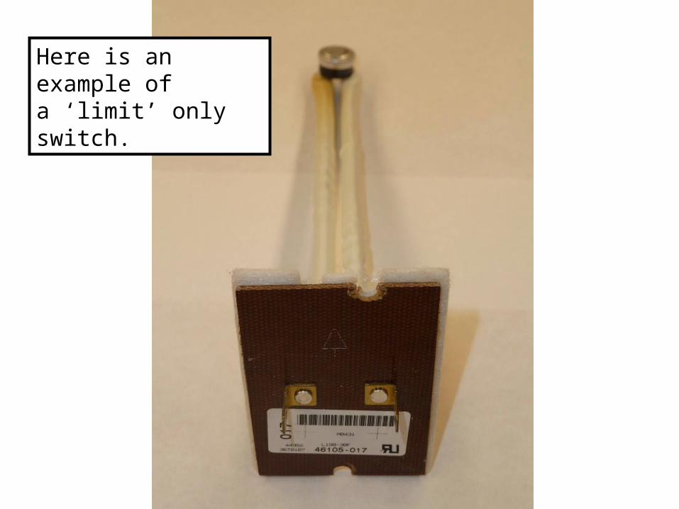
Here is an example ofa ‘limit’ only switch.
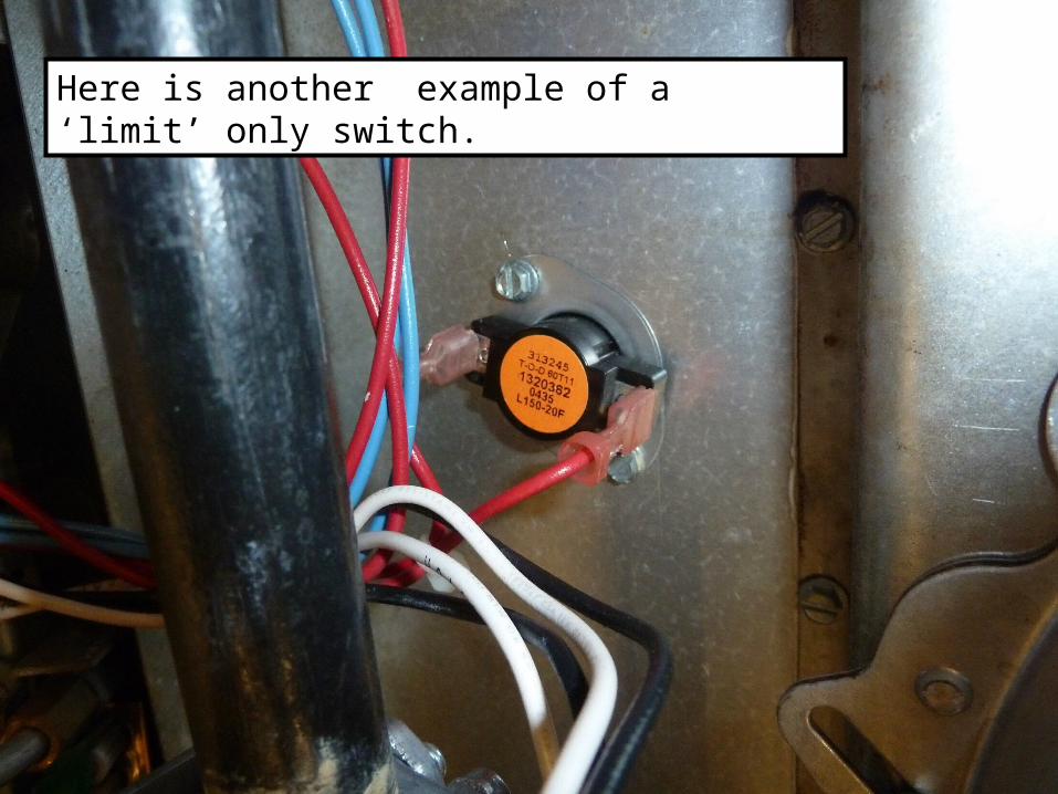
Here is another example of a ‘limit’ only switch.
FAN and LIMIT
As was stated earlier, the FAN switch is ALWAYS in the
POWER circuit, but the LIMIT switch may be found in
either the POWER circuit or the CONTROL circuit.
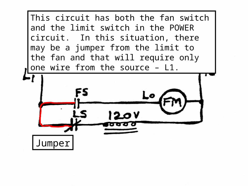
This circuit has both the fan switch and the limit switch in the POWER circuit. In this situation, there may be a jumper from the limit to the fan and that will require only one wire from the source – L1.
Jumper
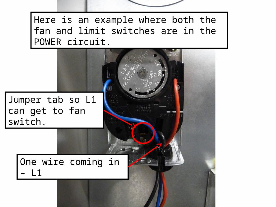
Here is an example where both the fan and limit switches are in the POWER circuit.
One wire coming in – L1
Jumper tab so L1 can get to fan switch.
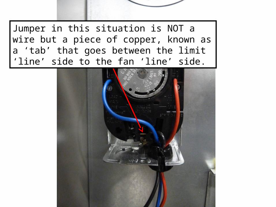
Jumper in this situation is NOT a wire but a piece of copper, known as a ‘tab’ that goes between the limit ‘line’ side to the fan ‘line’ side.
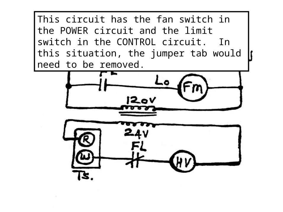
This circuit has the fan switch in the POWER circuit and the limit switch in the CONTROL circuit. In this situation, the jumper tab would need to be removed.
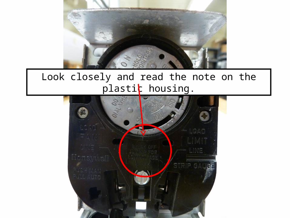
Look closely and read the note on the plastic housing.
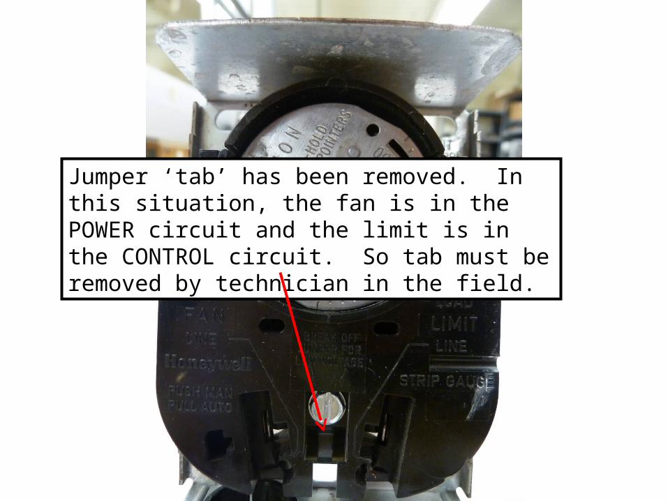
Jumper ‘tab’ has been removed. In this situation, the fan is in the POWER circuit and the limit is in the CONTROL circuit. So tab must be removed by technician in the field.
Fan and limit switches as found on
‘newer (modern)’ gas equipment.
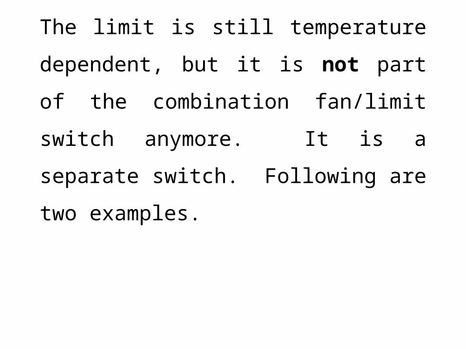
The limit is still temperature dependent,
but it is not part of the combination
fan/limit switch anymore. It is a separate
switch. Following are two examples.
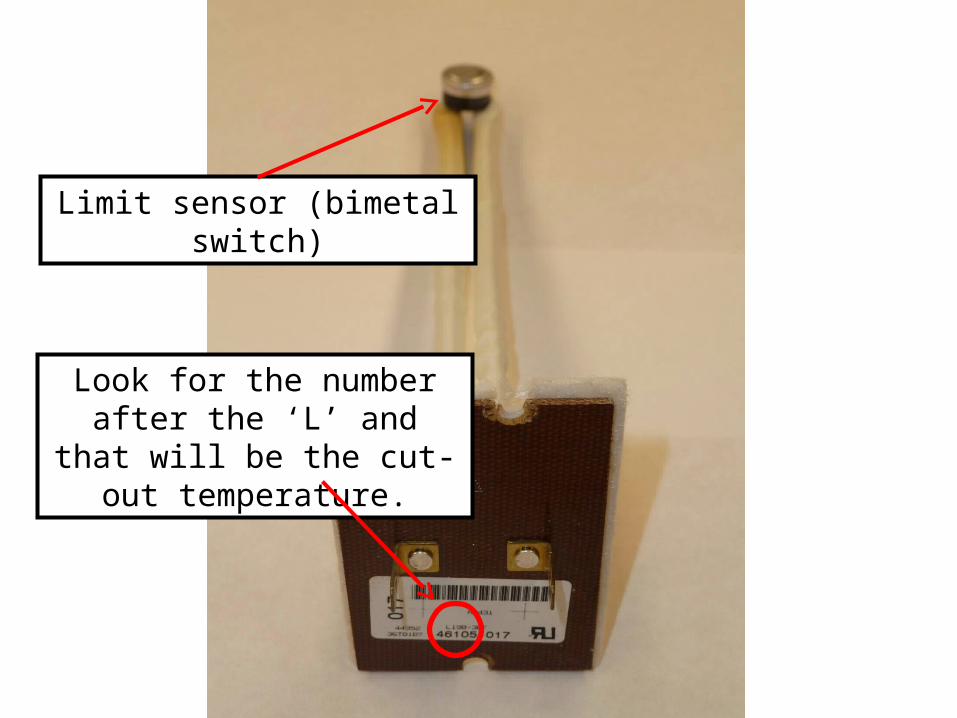
Limit sensor (bimetal switch)
Look for the number after the ‘L’ and that will be the cut-out
temperature.
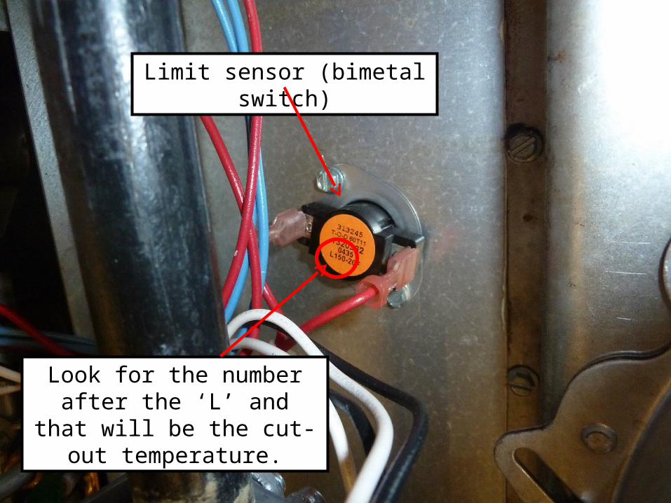
Limit sensor (bimetal switch)
Look for the number after the ‘L’ and that will be the cut-out
temperature.
The fan switch is no longer temperature
dependent. It is timed via the solid state control
board. DIP switches are used to set up the
time. Refer to manufacturers directions as to
position of DIP switches for timing. Additional
information can be found in your textbook and
on the equipment in the HAC lab.
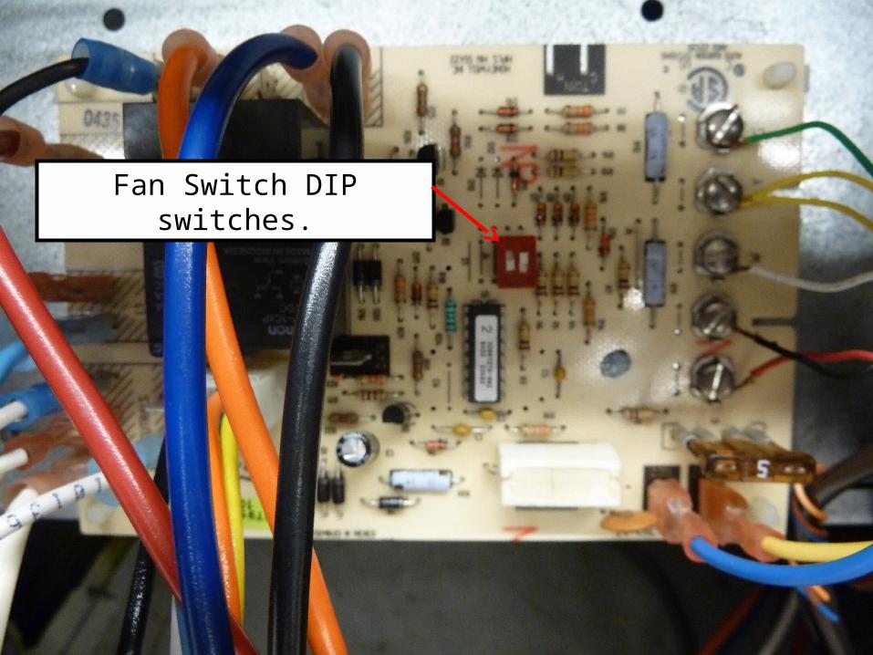
Fan Switch DIP switches.
Miscellaneous Information
(for tests)
When troubleshooting, what are the three circuits
a technician might have to troubleshoot?
1. Power
2. Control
3. Safety
What are the first three things you do when you
arrive on the job?
1. ASK the customer what they observed.
2. Check that the system switch on the
thermostat is properly set.
3. Set the thermostat to call for MAXIMUM heat.