fast radio interferometric measurement on low power cots ...mmaroti/pdf/talks/2014 fast radio...
TRANSCRIPT

Fast radio interferometric measurement on low power COTS radio chips
A. Bata, A. Bíró, Gy. Kalmár and M. MarótiUniversity of Szeged, Hungary
TÁMOP-4.2.2.A-11/1/KONV-2012-0073: Telemedicine oriented research in the fields of mathematics, informatics and medical sciences

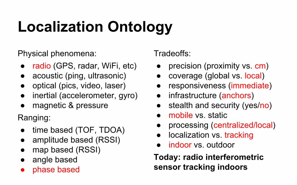
Localization OntologyPhysical phenomena:● radio (GPS, radar, WiFi, etc)● acoustic (ping, ultrasonic)● optical (pics, video, laser) ● inertial (accelerometer, gyro)● magnetic & pressure
Ranging:● time based (TOF, TDOA)● amplitude based (RSSI)● map based (RSSI)● angle based● phase based
Tradeoffs:● precision (proximity vs. cm)● coverage (global vs. local)● responsiveness (immediate)● infrastructure (anchors)● stealth and security (yes/no)● mobile vs. static● processing (centralized/local)● localization vs. tracking● indoor vs. outdoor
Today: radio interferometric sensor tracking indoors

Radio Interferometric Ranging● Two transmitters (A and B)
simultaneously send unmodulated sine waves at slightly different frequencies
● The interference is a high frequency amplitude modulated by a low frequency beat signal
● Two receivers (C and D) measure the phase of the beat signal at the same time
● Relative phase offset depends on the distances between A, B, C and D

Radio Interferometric Ranging● Test mode of COTS radio gives
unmodulated sine wave● Beat signal can be measured as
signal strength (RSSI)● Quad range: linear combination
of four ranges● Outdoor experiment:
○ 100 x 120m on football field○ 16 XSM (CC1000) nodes○ 400-460 MHz carrier○ Avg. localization error: 4cm○ Took 50 minutes long

Indoor Radio Interferometry● Outdoor solution does not
work indoors● Phase error depends on
carrier frequency● CC1000 radio is no longer
available● IDEA:
○ RFA1 vs. CC1000○ 2.4 GHz vs. 430 MHz○ Single freq tracking○ Significant speedup○ TDMA like schedule

Step 1: Sensor and RF Measurement● IEEE 802.15.4 compliant COTS
radio chip● Test mode: unmodulated wave● Fixed carrier frequencies
○ need 50-100 KHz offset○ trim the load capacitance
● Unpredictable carriers: ±40 KHz● Slow reset (switch to test mode)● Measure RSSI signal
○ designed for CCA and LQ○ low resolution (28 steps)○ good refresh rate (500 KHz)
● One measurement: 1 ms
● UCMote Proton A DRD● Atmega128RFA1 primary
radio with chip antenna● 8-bit 16 MHz microcontroller● 128 KB ROM, 16 KB RAM

Step 2: Signal Processing● Low resolution (28 steps)● Time synchronization
○ default is not precise○ use rising edge
● Unpredictable beat freq○ depends on carrier offset○ we expect 20-100 KHz
● Dynamic range○ depends on TX powers○ very small (1-5 steps)
● Device dependent noise● 0.65 ms processing time

Step 3: Distributed Schedule
TX
TX TX
RS
TX RX RX RS TX RX RX TX RX RX
RS TX RX RX
TS
TX TX TX
RS
RX TX RX RS RX TX RX
RS RX TX RX RS RX TX RX
TS
TX TX TX
RS
RX RX TX RS
RX RX TX RS RX RX TX RS RX RX TX
TS
TX TX TX
RSRS RS
TS
RS
A
B
C
D
xmit sync
TS
TS RS rcv sync xmit wave RX rcv rssi
TX
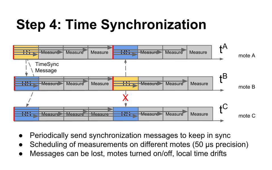
Step 4: Time Synchronization
mote A
mote B
mote C
tA
tB
tC
TS Measure Measure Measure RS Measure Measure Measure
RS Measure Measure Measure TS Measure Measure Measure
RS Measure Measure Measure RS Measure Measure Measure
TimeSync Message
X
● Periodically send synchronization messages to keep in sync● Scheduling of measurements on different motes (50 μs precision)● Messages can be lost, motes turned on/off, local time drifts

Step 5: Data Extraction and Timing
SLOT ID PERIOD1 ... PERIOD N
PHASE 1 ... PHASE
NTIME-
STAMP
● All measurements (8-bit period and 8-bit phase) in a frame are packed into a single synchronization message
● Data is arriving out of order to the base station ● Measurement timing
○ Single measurement: 1 ms○ Synchronization msg: 2.5 ms○ Processing and runtime overhead: 3 ms○ SuperFrame (4 sync msg, 12 measurements): 25 ms○ One relative phase per pair of transmitters: 12.5 ms (80 Hz)

Step 6: Sort Data on Basestation
T T T 1 2 T 3 4 T 5 6
T 5 6 T T T 1 T 2 3 T 4
3 T 4 5 T 6 T T T 1 2 T
1 2 T 3 4 T 5 6 T T T T
T T T T 1 2 T 3 4 T 6
T 5 6 T T T 1 T 2 3 T 4
3 T 4 5 T 6 T T T 1 2 T
1 2 T 3 4 T 5 6 T T T T
T
Super Frame Super Frame
Frame
5
Syn
c A
Syn
c B
Syn
c C
Syn
c D
Syn
c C
Syn
c B
Syn
c D
Syn
c A
mote A mote B mote C mote D

Step 7: Calculate Relative Phases● Find matching pair of absolute phase measurements● Filter out incorrect measurements
○ different error codes from signal processing unit○ the two periods are not close enough
● Calculate relative phase: this is between 0 and 2π● Unwrap relative phases to a number
○ Calculate speed (difference of twoconsecutive relative phases)
○ Filter out big speed jumps○ Integrate to get unwrapped phase
● The unwrapped phase is the level on thesurface with the hyperbolic geodesics

Demo:

Thank you!
TÁMOP-4.2.2.A-11/1/KONV-2012-0073: Telemedicine oriented research in the fields of mathematics, informatics and medical sciences