filter design1
TRANSCRIPT
Microwave Filter DesignBy
Professor Syed Idris Syed Hassan
Sch of Elect. & Electron Eng
Engineering Campus USM
Nibong Tebal 14300
SPS Penang
Contents
2
1. Composite filter2. LC ladder filter3. Microwave filter
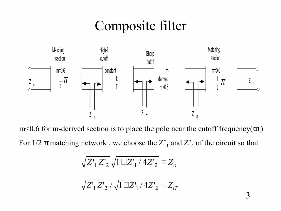
Composite filter
3
m=0.6 m=0.6m-derivedm<0.6
constantkT
π2
1 π2
1
Matchingsection
Matchingsection
High-fcutoff
Sharpcutoff
Z iTZ iT Z iT
Z oZ o
m<0.6 for m-derived section is to place the pole near the cutoff frequency(ωc)
oZZZZZ =+ 2121 '4/'1''
iTZZZZZ =+ 2121 '4/'1/''
For 1/2 π matching network , we choose the Z’1 and Z’2 of the circuit so that
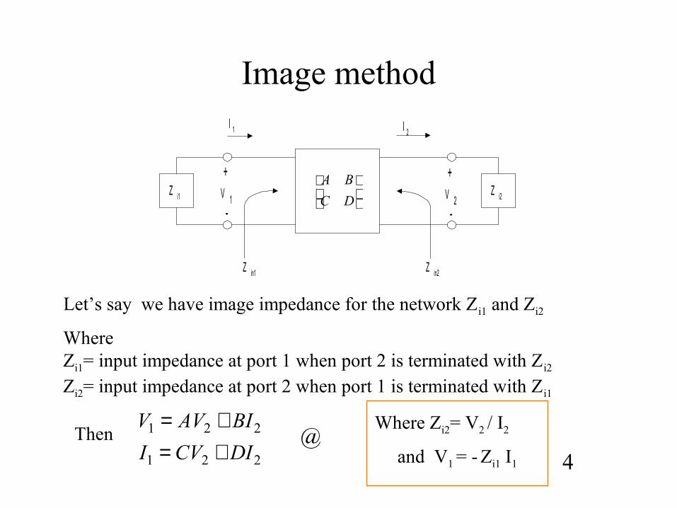
Image method
DC
BAZ i1 Z i2
I 1 I 2
+V 1
-
+V 2
-
Z in1 Z in2
221
221
DICVI
BIAVV
+=+=
Let’s say we have image impedance for the network Zi1 and Zi2
Where Zi1= input impedance at port 1 when port 2 is terminated with Zi2
Zi2= input impedance at port 2 when port 1 is terminated with Zi1
Then
4@
Where Zi2= V2 / I2
and V1 = - Zi1 I1
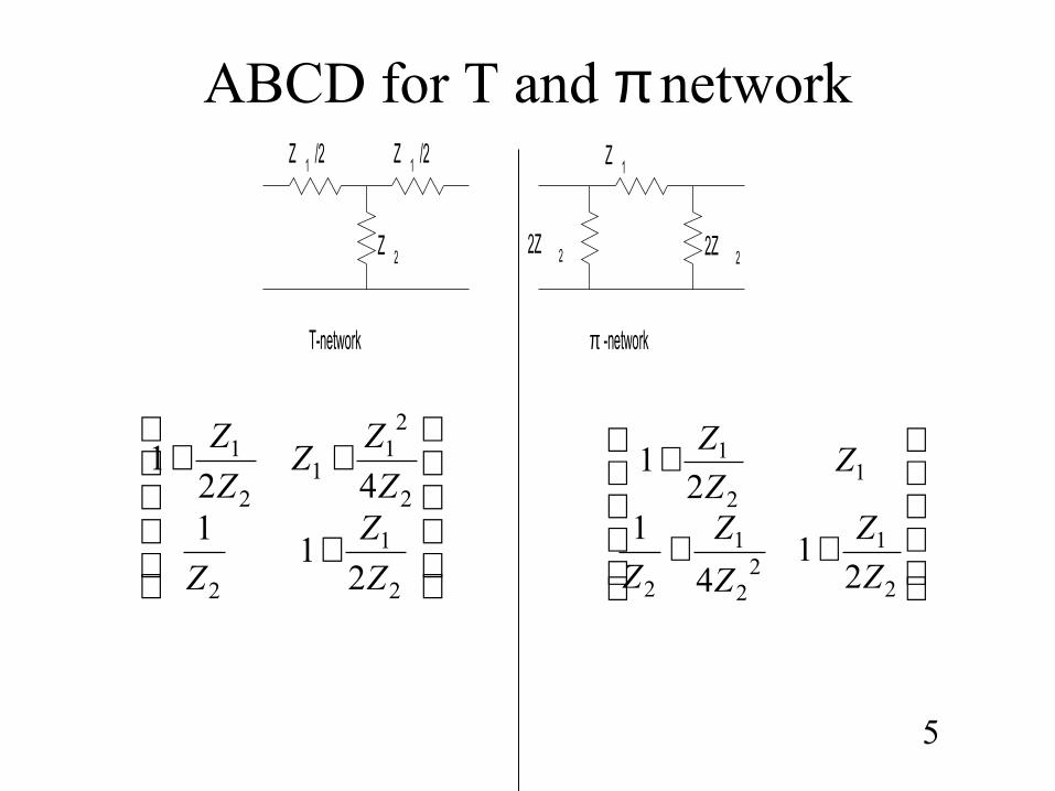
ABCD for T and π network
5
Z 1 /2 Z 1 /2
Z 2
Z 1
2Z 2 2Z 2
T-network π -network
++
+
2
12
2
1
2
12
1
21
4
12
1
Z
Z
Z
Z
Z
ZZ
Z
+
++
2
1
2
2
21
12
1
21
142
1
Z
Z
Z
Z
ZZ
Z
Z
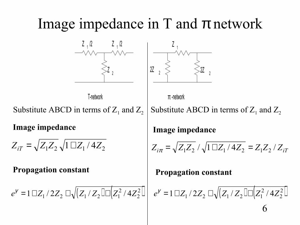
Image impedance in T and π network
6
Z 1 /2 Z 1 /2
Z 2
Z 1
2Z 2 2Z 2
T-network π -network
2121 4/1 ZZZZZiT +=
( ) ( )22
212121 4//2/1 ZZZZZZe +++=γ
iTi ZZZZZZZZ /4/1/ 212121 =+=π
( ) ( )22
212121 4//2/1 ZZZZZZe +++=γ
Image impedance Image impedance
Propagation constant Propagation constant
Substitute ABCD in terms of Z1 and Z2 Substitute ABCD in terms of Z1 and Z2
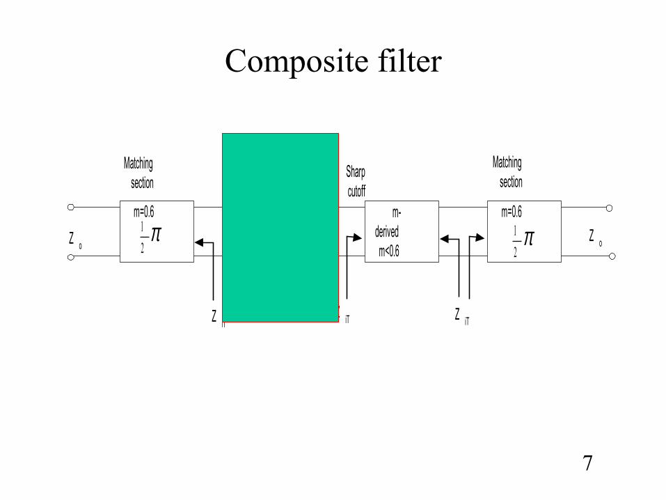
Composite filter
7
m=0.6 m=0.6m-derivedm<0.6
constantkT
π2
1 π2
1
Matchingsection
Matchingsection
High-fcutoff
Sharpcutoff
Z iTZ iT Z iT
Z oZ o
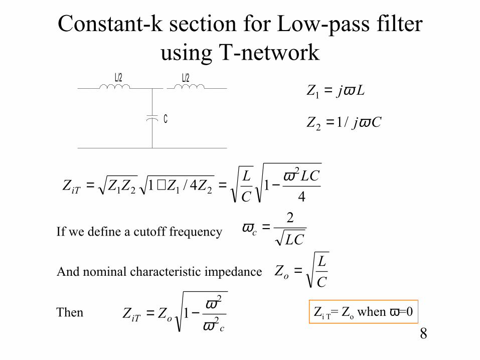
Constant-k section for Low-pass filter using T-network
8
L/2
C
L/2
414/1
2
2121LC
C
LZZZZZiT
ω−=+=
LjZ ω=1
CjZ ω/12 =
If we define a cutoff frequency LC
c2=ω
And nominal characteristic impedanceC
LZo =
Thenc
oiT ZZ2
2
1ωω−= Zi T= Zo when ω=0
continue
9
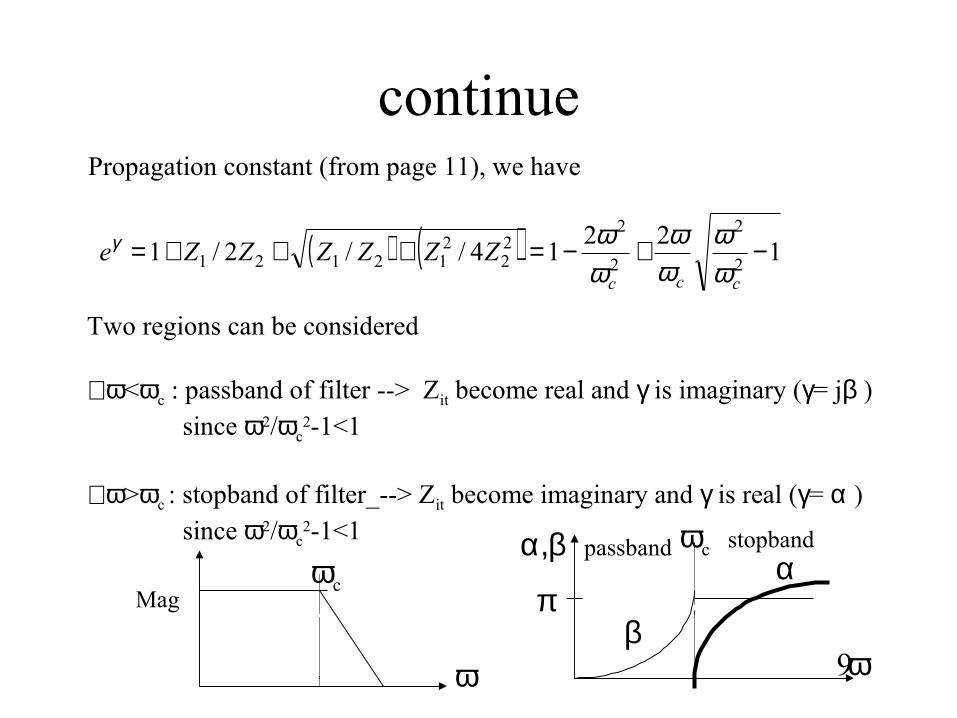
Propagation constant (from page 11), we have
( ) ( ) 122
14//2/12
2
2
222
212121 −+−=+++=
ccc
ZZZZZZeωω
ωω
ωωγ
Two regions can be considered
∀ω<ωc : passband of filter --> Zit become real and γ is imaginary (γ= jβ )since ω2/ωc
2-1<1
∀ω>ωc : stopband of filter_--> Zit become imaginary and γ is real (γ= α ) since ω2/ωc
2-1<1
ωc
ω
Mag
ωcα,β
ω
πβ
αpassband stopband
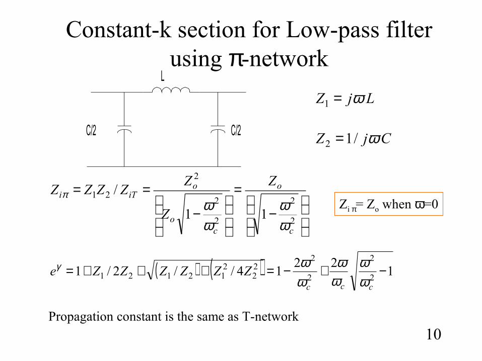
Constant-k section for Low-pass filter using π-network
10
LjZ ω=1
CjZ ω/12 =
−
=
−
==
2
2
2
2
2
21
11
/
c
o
co
oiTi
Z
Z
ZZZZZ
ωω
ωω
π
( ) ( ) 122
14//2/12
2
2
222
212121 −+−=+++=
ccc
ZZZZZZeωω
ωω
ωωγ
Zi π= Zo when ω=0
Propagation constant is the same as T-network
C/2
L
C/2
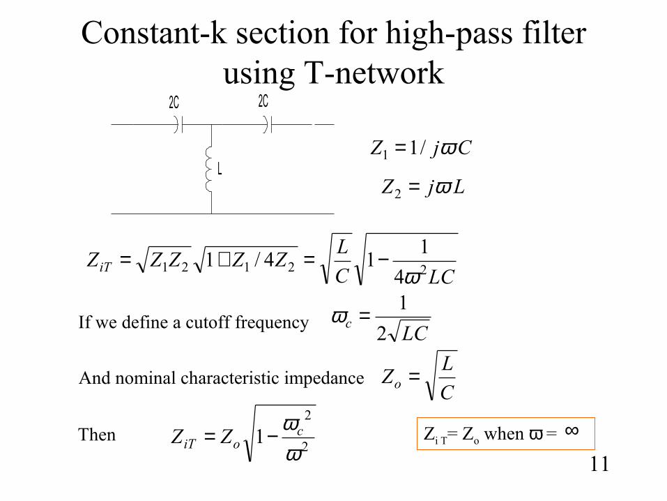
Constant-k section for high-pass filter using T-network
11
LCC
LZZZZZiT 22121
4
114/1
ω−=+=
CjZ ω/11 =
LjZ ω=2
If we define a cutoff frequency LC
c2
1=ω
And nominal characteristic impedanceC
LZo =
Then2
2
1ωωc
oiT ZZ −= Zi T= Zo when ω = ∞
2C
L
2C
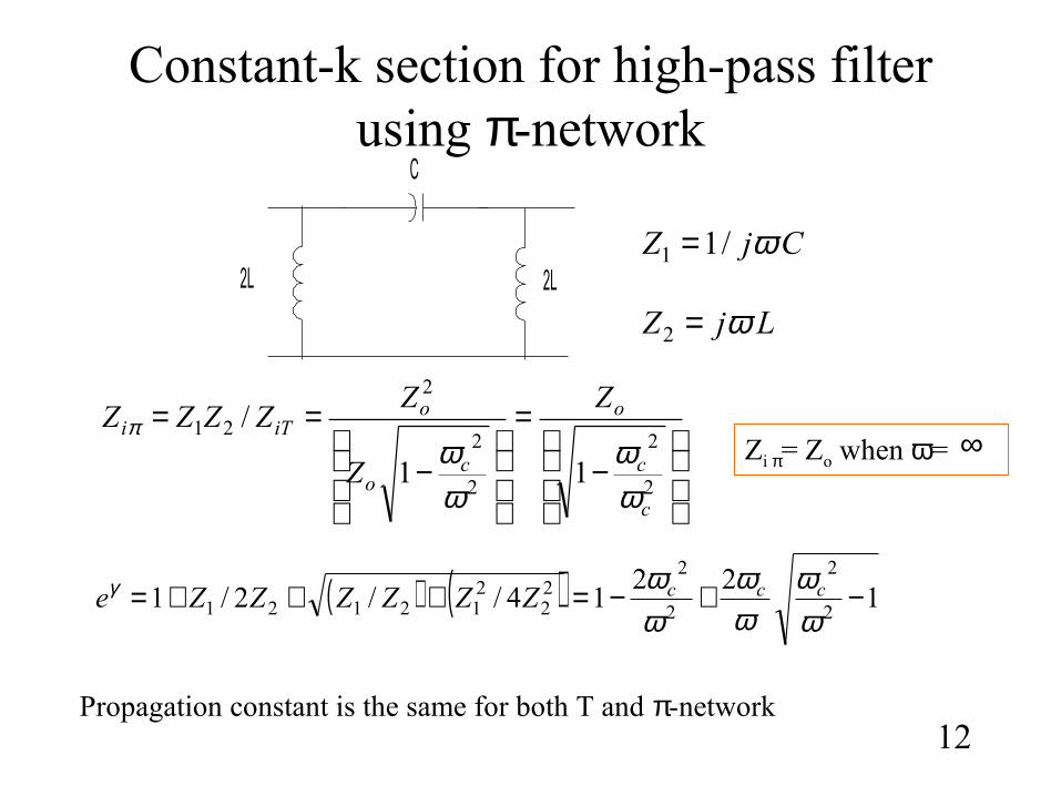
Constant-k section for high-pass filter using π-network
12
CjZ ω/11 =
LjZ ω=2
−
=
−
==
2
2
2
2
2
21
11
/
c
c
o
co
oiTi
Z
Z
ZZZZZ
ωω
ωω
π
( ) ( ) 122
14//2/12
2
2
222
212121 −+−=+++=
ωω
ωω
ωωγ cccZZZZZZe
Zi π= Zo when ω=
Propagation constant is the same for both T and π-network
∞
2L
C
2L
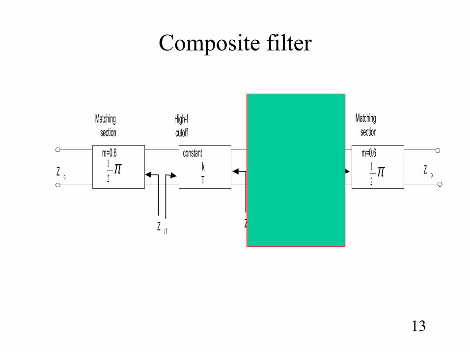
Composite filter
13
m=0.6 m=0.6m-derivedm<0.6
constantkT
π2
1 π2
1
Matchingsection
Matchingsection
High-fcutoff
Sharpcutoff
Z iTZ iT Z iT
Z oZ o
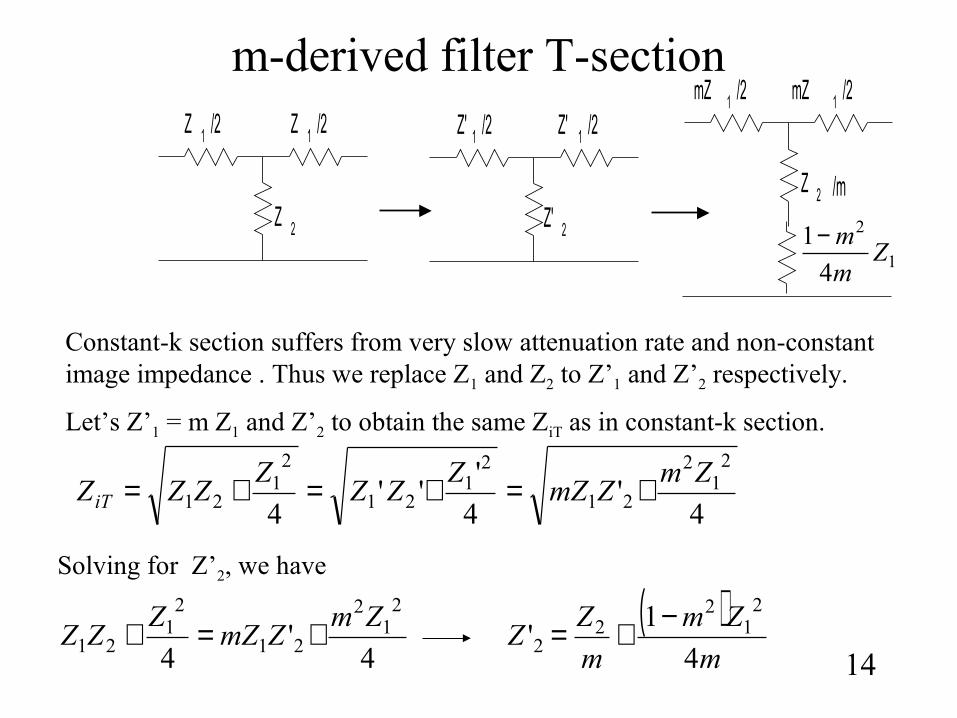
m-derived filter T-section
14
Z 1 /2 Z 1 /2
Z 2
Z' 1 /2 Z' 1 /2
Z' 2
mZ 1 /2 mZ 1 /2
Z 2 /m
1
2
4
1Z
m
m−
Constant-k section suffers from very slow attenuation rate and non-constant image impedance . Thus we replace Z1 and Z2 to Z’1 and Z’2 respectively.
Let’s Z’1 = m Z1 and Z’2 to obtain the same ZiT as in constant-k section.
4'
4
'''
4
21
2
21
21
21
21
21Zm
ZmZZ
ZZZ
ZZZiT +=+=+=
4'
4
21
2
21
21
21Zm
ZmZZ
ZZ +=+
Solving for Z’2, we have
( )m
Zm
m
ZZ
4
1'
21
22
2−+=
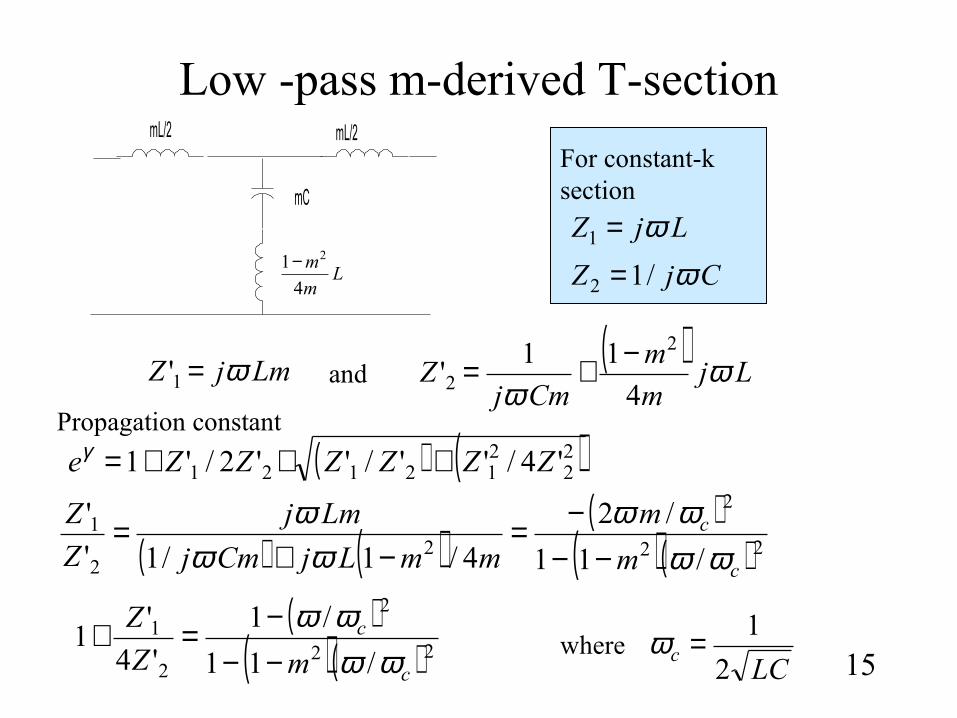
Low -pass m-derived T-section
15
Lm
m
4
1 2−
mC
mL/2mL/2
LjZ ω=1
CjZ ω/12 =
For constant-k section
LmjZ ω=1'( )
Ljm
m
CmjZ ω
ω 4
11'
2
2−+=and
( ) ( )22
212121 '4/''/''2/'1 ZZZZZZe +++=γ
( ) ( )( )
( )( ) 22
2
22
1
/11
/2
4/1/1'
'
c
c
m
m
mmLjCmj
Lmj
Z
Z
ωωωω
ωωω
−−−=
−+=
( )( )( ) 22
2
2
1
/11
/1
'4
'1
c
c
mZ
Z
ωωωω
−−−=+
Propagation constant
LCc
2
1=ωwhere
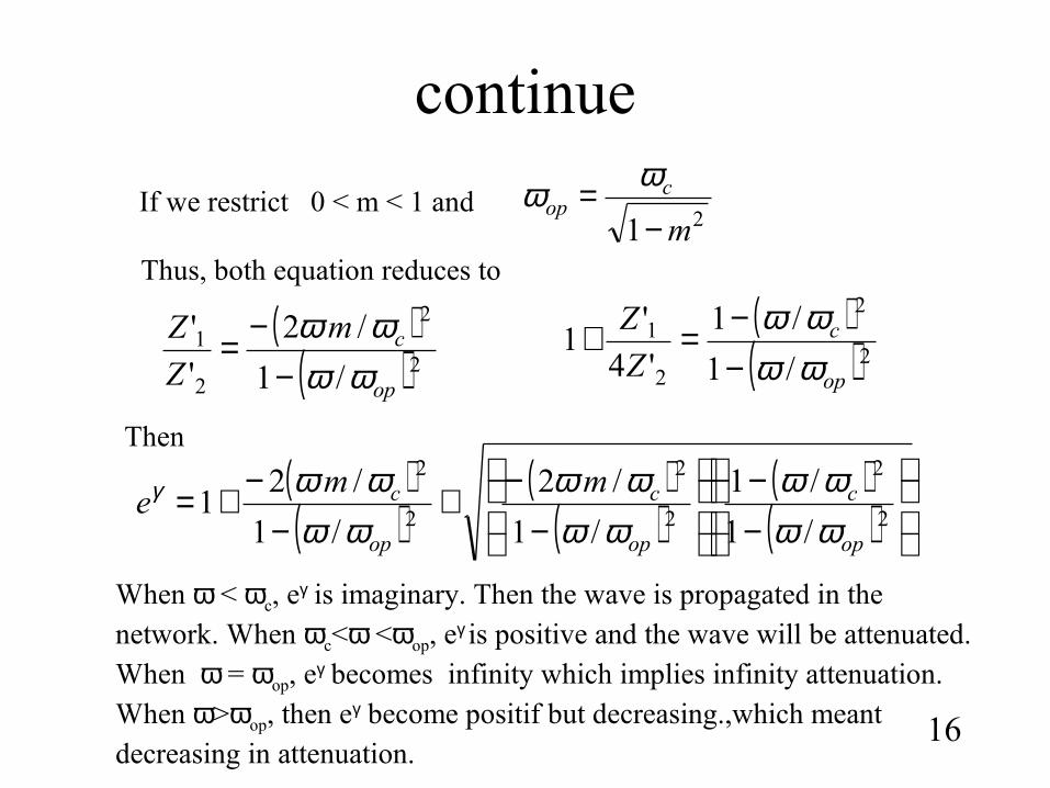
continue
16
( )( )2
2
2
1
/1
/1
'4
'1
op
c
Z
Z
ωωωω
−−=+( )
( )2
2
2
1
/1
/2
'
'
op
cm
Z
Z
ωωωω
−−=
If we restrict 0 < m < 1 and 21 m
cop
−= ωω
Thus, both equation reduces to
( )( )
( )( )
( )( )
−−
−−+
−−+=
2
2
2
2
2
2
/1
/1
/1
/2
/1
/21
op
c
op
c
op
c mme
ωωωω
ωωωω
ωωωωγ
Then
When ω < ωc, eγ is imaginary. Then the wave is propagated in the network. When ωc<ω <ωop, eγ is positive and the wave will be attenuated. When ω = ωop, eγ becomes infinity which implies infinity attenuation. When ω>ωop, then eγ become positif but decreasing.,which meant decreasing in attenuation.
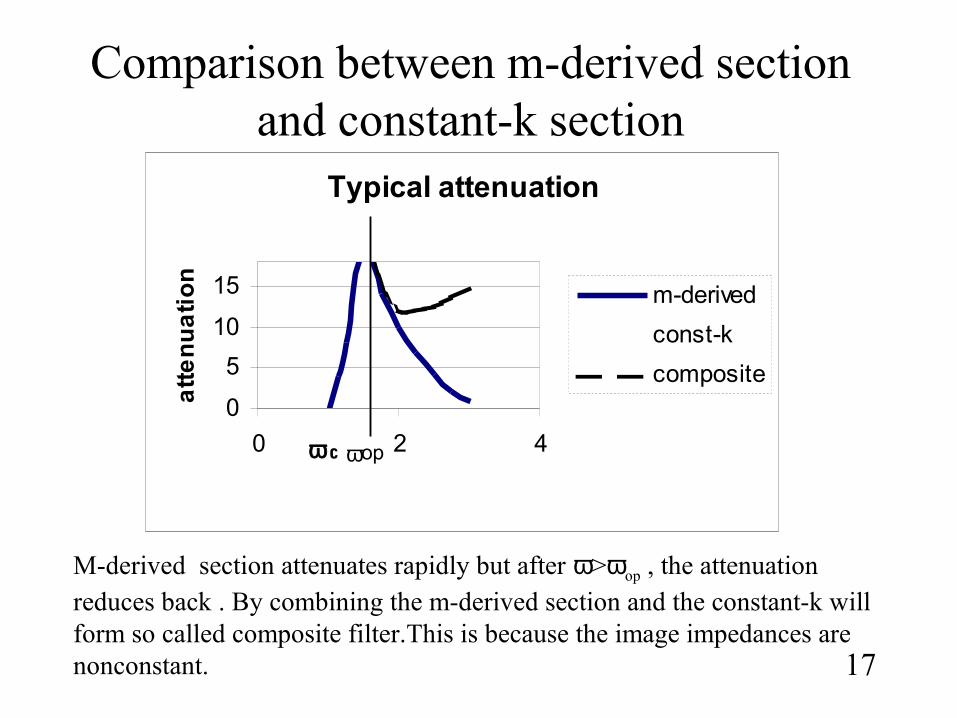
Comparison between m-derived section and constant-k section
17
Typical attenuation
0
5
10
15
0 2 4ω c
att
en
ua
tio
n
m-derived
const-k
composite
ωop
M-derived section attenuates rapidly but after ω>ωop , the attenuation reduces back . By combining the m-derived section and the constant-k will form so called composite filter.This is because the image impedances are nonconstant.
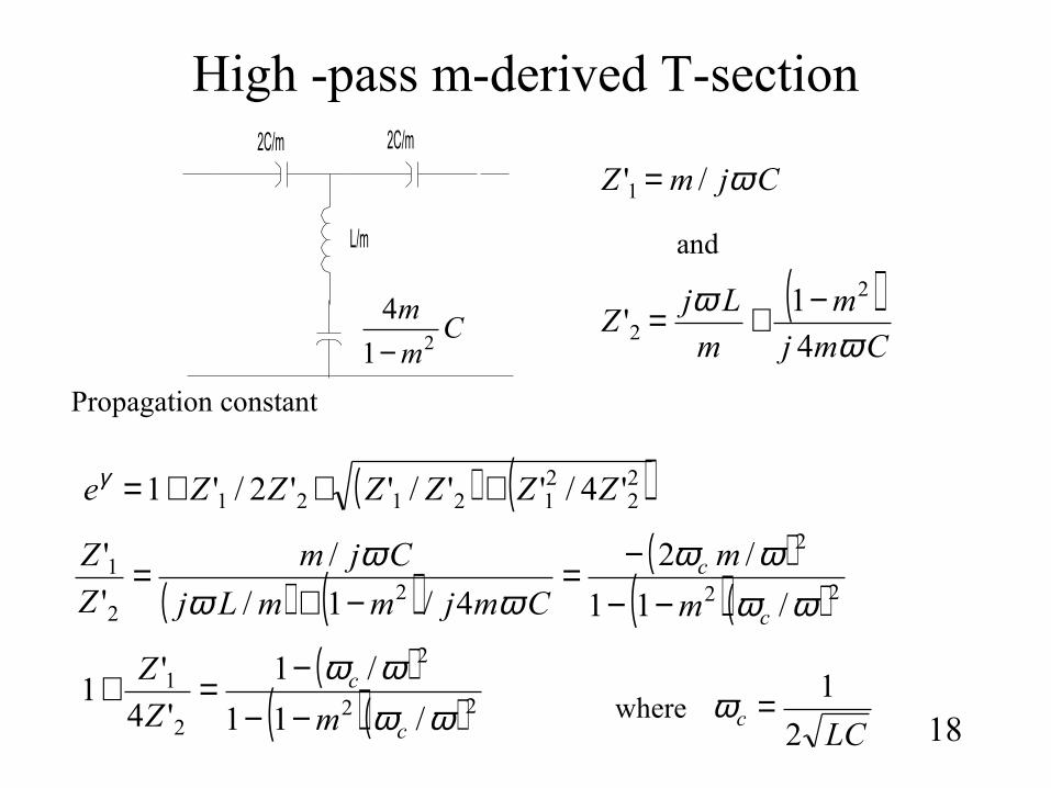
High -pass m-derived T-section
18
2C/m
L/m
2C/m
Cm
m21
4
−
CjmZ ω/'1 =
( )Cmj
m
m
LjZ
ωω
4
1'
2
2−+=
and
( ) ( )22
212121 '4/''/''2/'1 ZZZZZZe +++=γ
( ) ( )( )
( )( ) 22
2
22
1
/11
/2
4/1/
/
'
'
ωωωω
ωωω
c
c
m
m
CmjmmLj
Cjm
Z
Z
−−−=
−+=
( )( )( ) 22
2
2
1
/11
/1
'4
'1
ωωωω
c
c
mZ
Z
−−−=+
Propagation constant
LCc
2
1=ωwhere
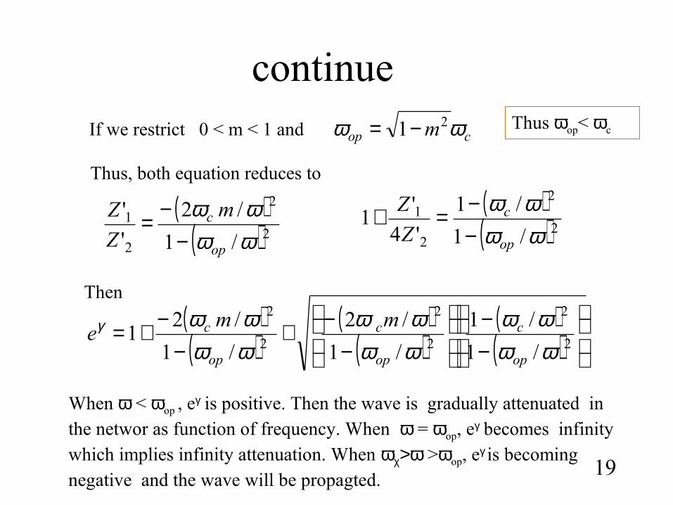
continue
19
( )( )2
2
2
1
/1
/1
'4
'1
ωωωω
op
c
Z
Z
−−=+( )
( )2
2
2
1
/1
/2
'
'
ωωωω
op
c m
Z
Z
−−=
If we restrict 0 < m < 1 and cop m ωω 21−=
Thus, both equation reduces to
( )( )
( )( )
( )( )
−−
−−+
−−+=
2
2
2
2
2
2
/1
/1
/1
/2
/1
/21
ωωωω
ωωωω
ωωωωγ
op
c
op
c
op
c mme
Then
When ω < ωop , eγ is positive. Then the wave is gradually attenuated in the networ as function of frequency. When ω = ωop, eγ becomes infinity which implies infinity attenuation. When ωχ>ω >ωop, eγ is becoming negative and the wave will be propagted.
Thus ωop< ωc
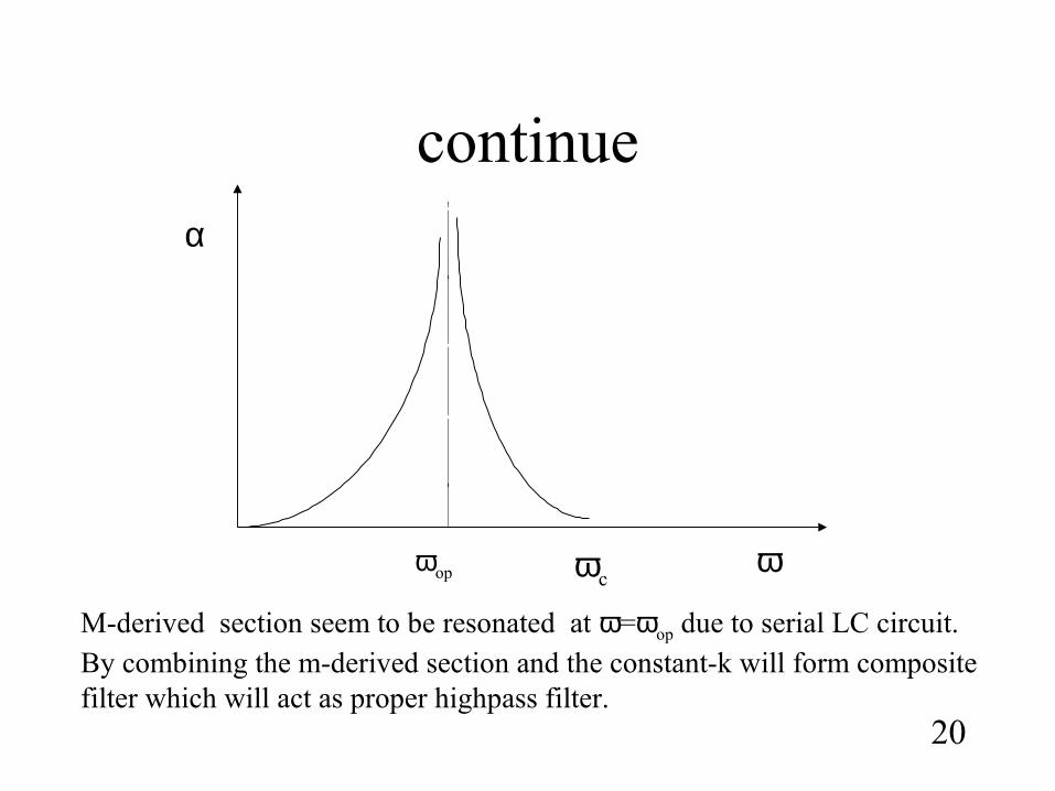
continue
20
α
ωωop ωc
M-derived section seem to be resonated at ω=ωop due to serial LC circuit. By combining the m-derived section and the constant-k will form composite filter which will act as proper highpass filter.
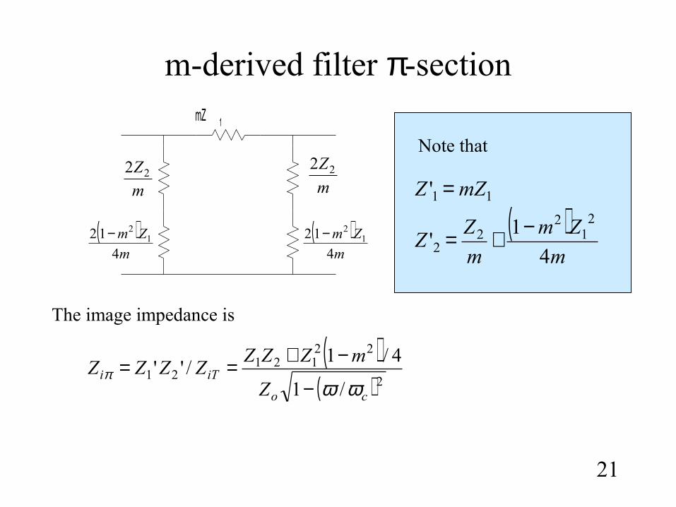
m-derived filter π-section
21
mZ 1
m
Z22
m
Z22
( )m
Zm
4
12 12−( )
m
Zm
4
12 12−
( )( ) 2
22121
21/1
4/1/''
co
iTiZ
mZZZZZZZ
ωωπ
−
−+==
11' mZZ =
( )m
Zm
m
ZZ
4
1'
21
22
2−+=
Note that
The image impedance is
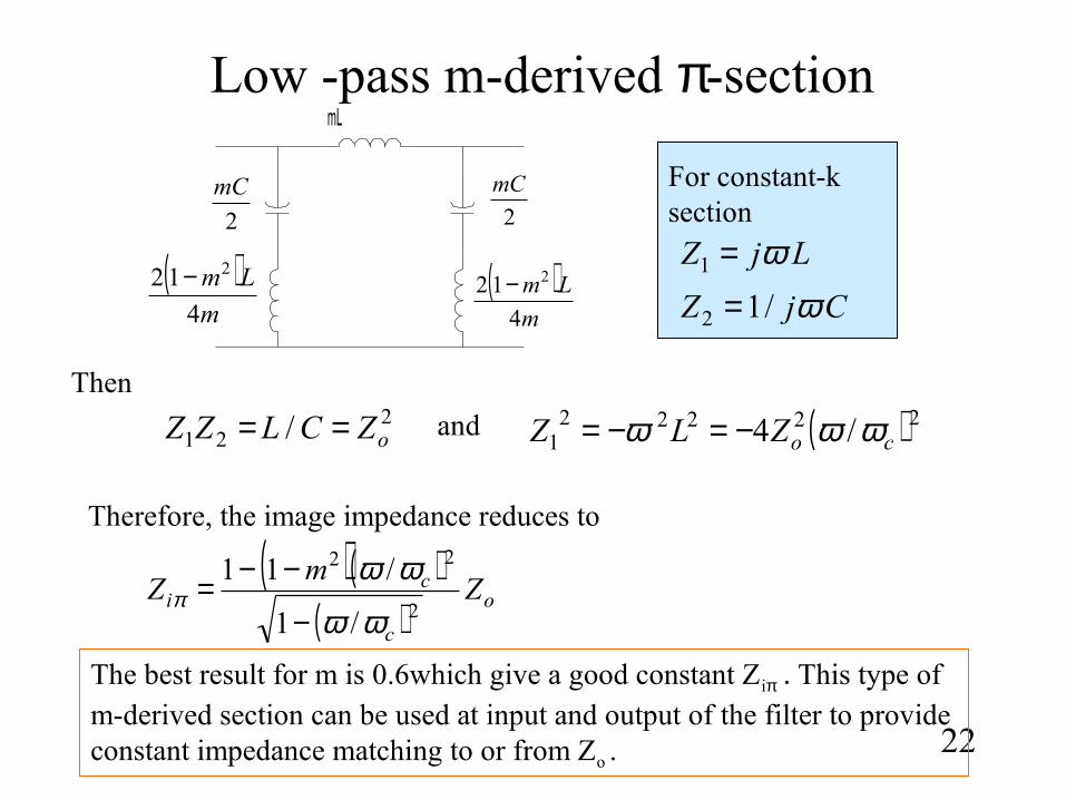
Low -pass m-derived π-section
22
mL
2
mC
2
mC
( )m
Lm
4
12 2−( )m
Lm
4
12 2−LjZ ω=1
CjZ ω/12 =
For constant-k section
221 / oZCLZZ == ( ) 22222
1 /4 coZLZ ωωω −=−=Then
and
Therefore, the image impedance reduces to
( )( )( ) o
c
ci Z
mZ
2
22
/1
/11
ωω
ωωπ
−
−−=
The best result for m is 0.6which give a good constant Ziπ . This type of m-derived section can be used at input and output of the filter to provide constant impedance matching to or from Zo .
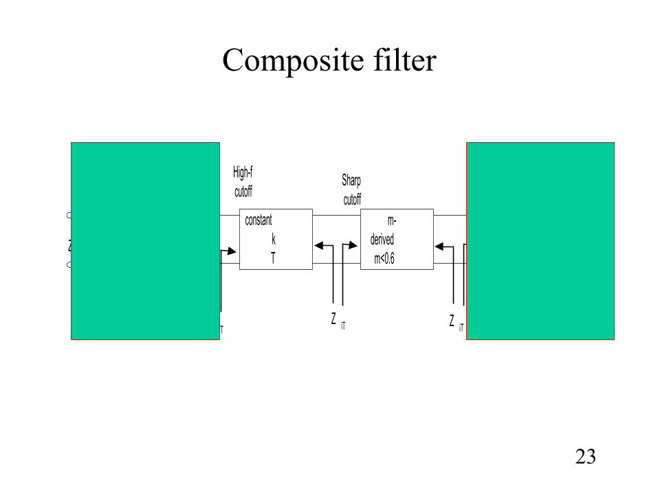
Composite filter
23
m=0.6 m=0.6m-derivedm<0.6
constantkT
π2
1 π2
1
Matchingsection
Matchingsection
High-fcutoff
Sharpcutoff
Z iTZ iT Z iT
Z oZ o
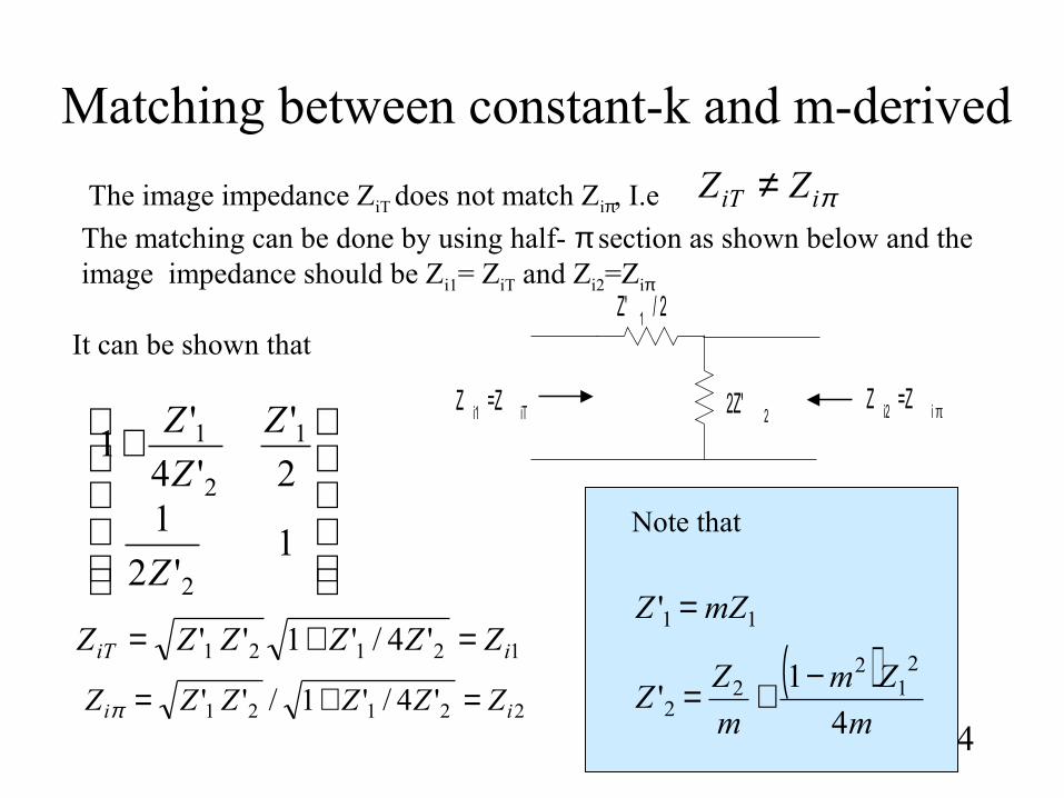
Matching between constant-k and m-derived
24
πiiT ZZ ≠The image impedance ZiT does not match Ziπ, I.e
The matching can be done by using half- π section as shown below and the image impedance should be Zi1= ZiT and Zi2=Ziπ
Z' 1 / 2
2Z' 2Z i2 =Z i πZ i1 =Z iT
+
1'2
12
'
'4
'1
2
1
2
1
Z
Z
Z
Z
12121 '4/'1'' iiT ZZZZZZ =+=
22121 '4/'1/'' ii ZZZZZZ =+=π
It can be shown that
11' mZZ =
( )m
Zm
m
ZZ
4
1'
21
22
2−+=
Note that
Example #1
25
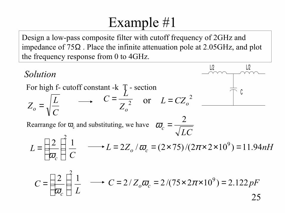
Design a low-pass composite filter with cutoff frequency of 2GHz and impedance of 75Ω . Place the infinite attenuation pole at 2.05GHz, and plot the frequency response from 0 to 4GHz.
SolutionFor high f- cutoff constant -k T - section
C
L/2 L/2
LCc
2=ωC
LZo =
LC
c
122
=
ω
2oZ
LC = 2
oCZL =or
CL
c
122
=
ω
Rearrange for ωc and substituting, we have
nHZL co 94.11)1022/()752(/2 9 =×××== πω
pFZC co 122.2)10275/(2/2 9 =××== πω
continue
26
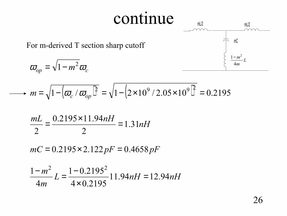
cop m ωω 21−=
( ) ( ) 2195.01005.2/1021/12992 =××−=−= opcm ωω
For m-derived T section sharp cutoff
nHnHmL
31.12
94.112195.0
2=×=
pFpFmC 4658.0122.22195.0 =×=
nHnHLm
m94.1294.11
2195.04
2195.01
4
1 22
=×
−=−
Lm
m
4
1 2−
mC
mL/2mL/2
continue
27
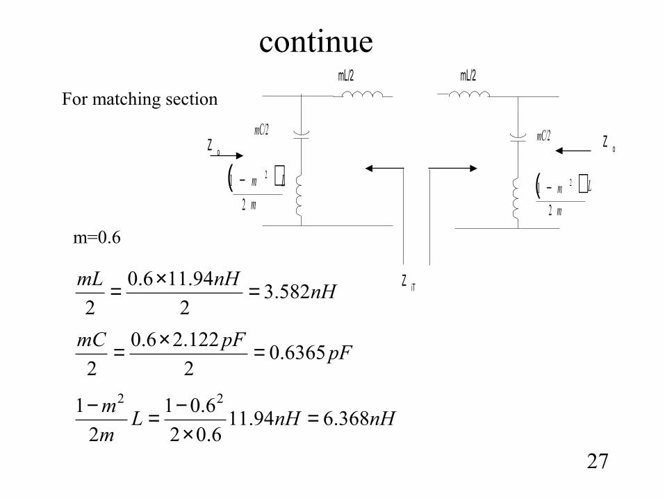
For matching sectionmL/2
mC/2mC/2
( )m
Lm
2
1 2−( )m
Lm
2
1 2−
mL/2
Z iT
Z oZ o
m=0.6
nHnHmL
582.32
94.116.0
2=×=
pFpFmC
6365.02
122.26.0
2=×=
nHnHLm
m368.694.11
6.02
6.01
2
1 22
=×
−=−
continue
28
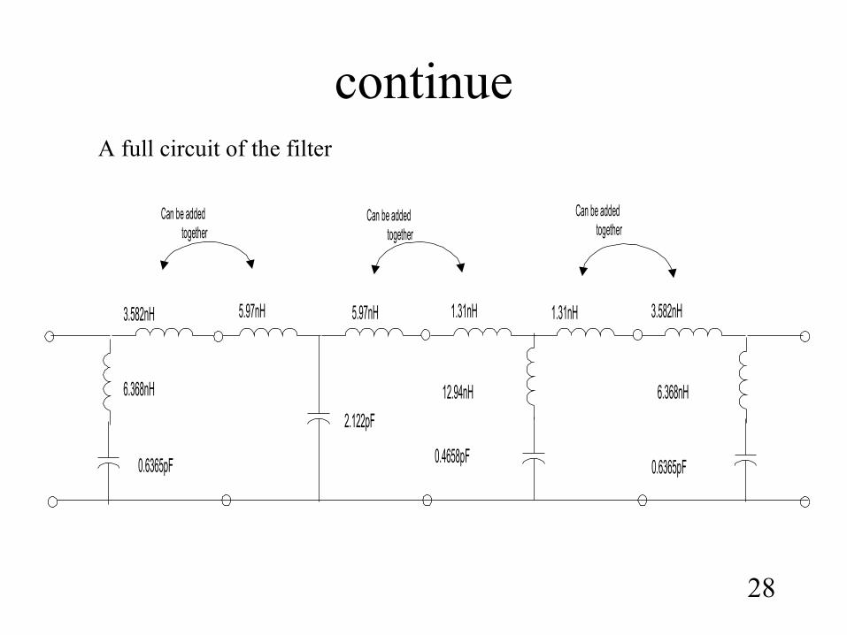
3.582nH 5.97nH 1.31nH
6.368nH
0.6365pF
2.122pF
12.94nH
0.4658pF
3.582nH
6.368nH
0.6365pF
1.31nH5.97nH
Can be addedtogether
Can be addedtogether
Can be addedtogether
A full circuit of the filter
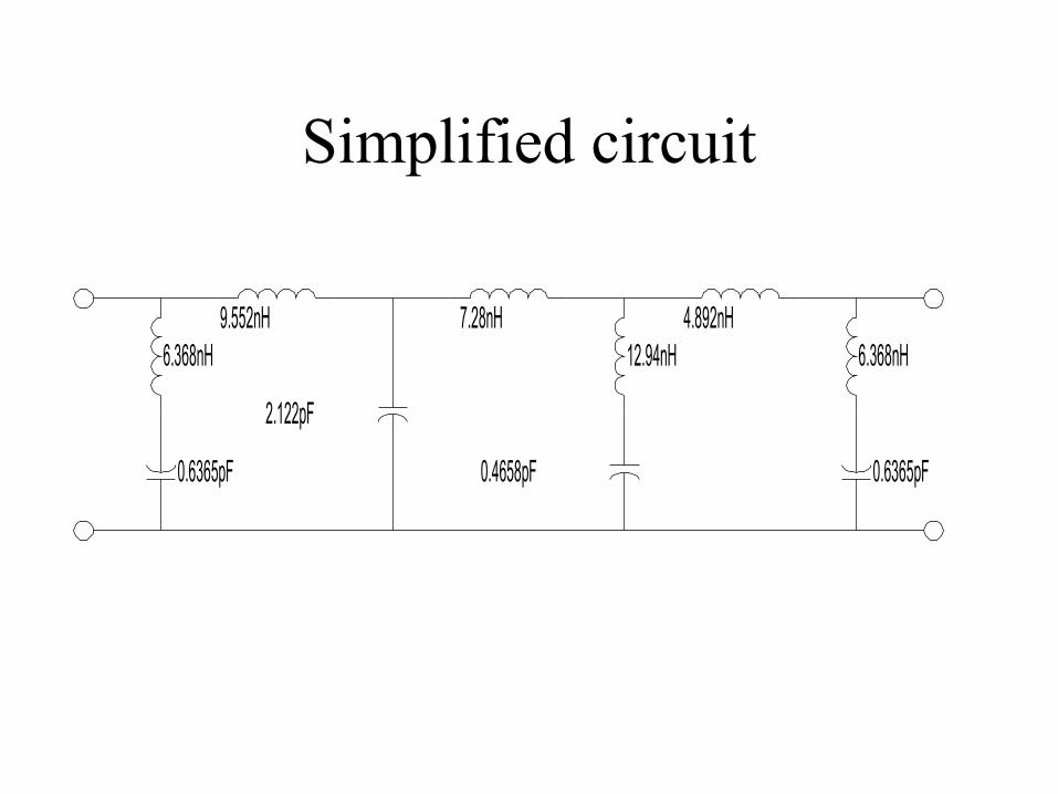
Simplified circuit
12.94nH9.552nH
6.368nH7.28nH 4.892nH
0.6365pF 0.6365pF0.4658pF
2.122pF
6.368nH
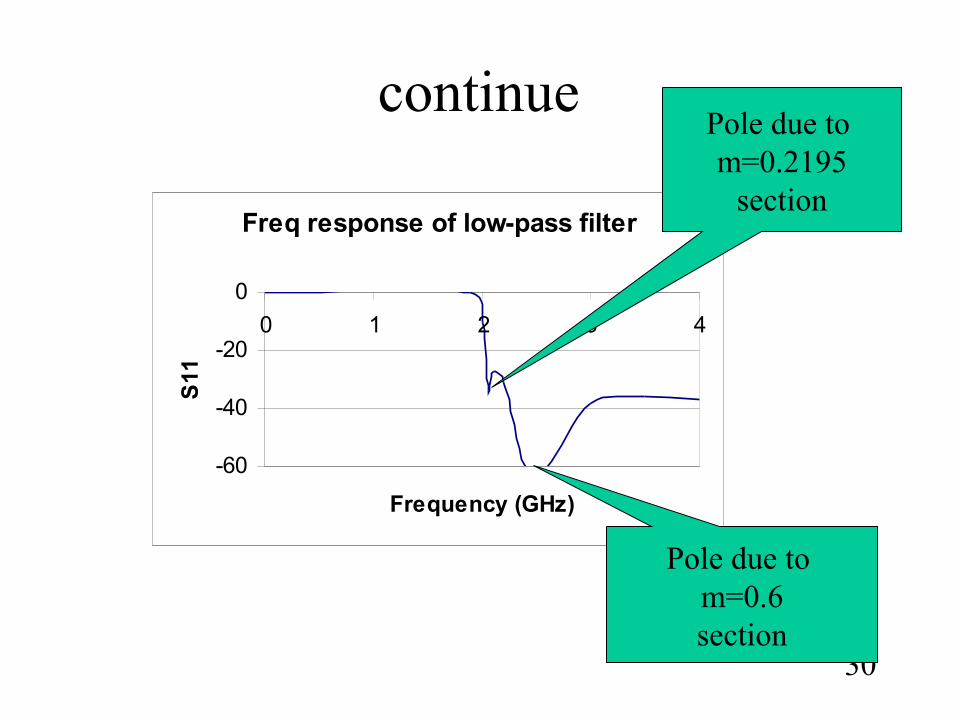
continue
30
Freq response of low-pass filter
-60
-40
-20
0
0 1 2 3 4
Frequency (GHz)
S11
Pole due to m=0.2195
section
Pole due to m=0.6section
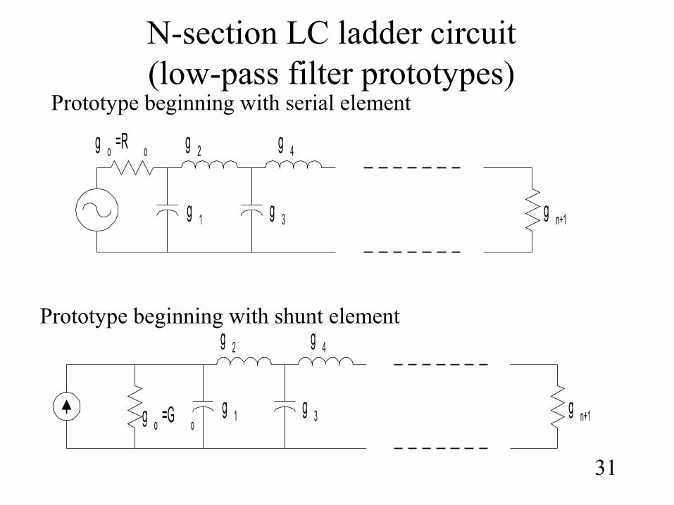
N-section LC ladder circuit(low-pass filter prototypes)
31
g o =G og 1
g 2
g 3
g 4
g n+1
g o =R o
g 1
g 2
g 3
g 4
g n+1
Prototype beginning with serial element
Prototype beginning with shunt element
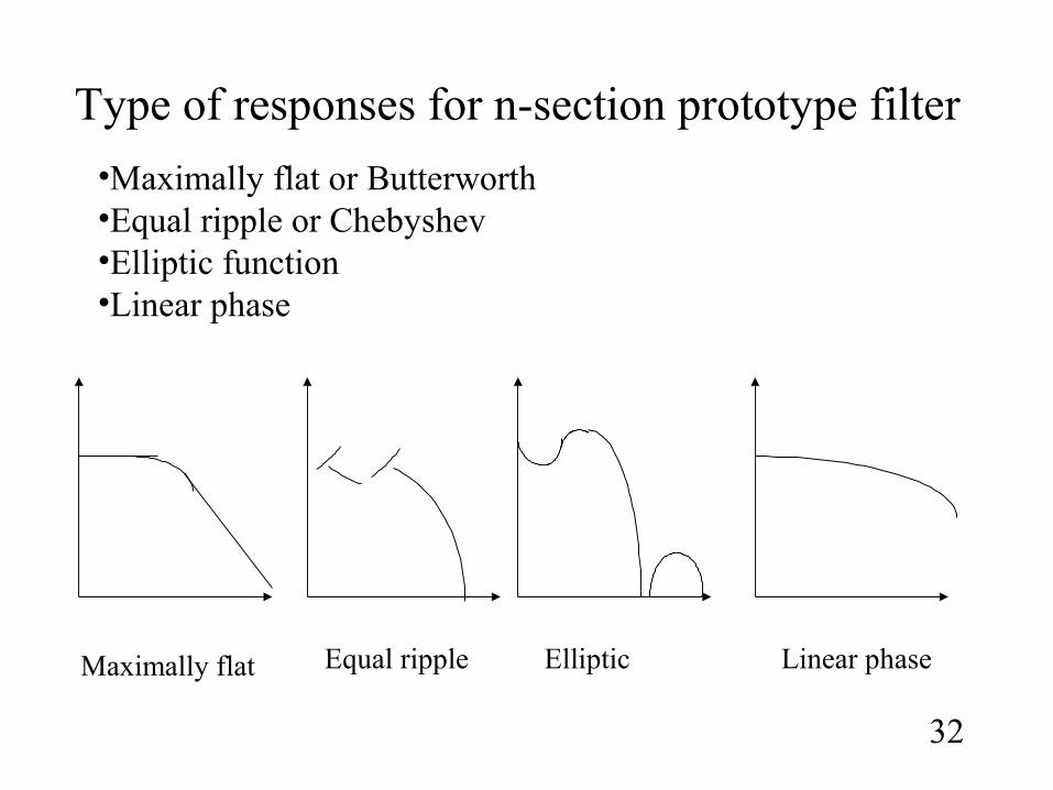
Type of responses for n-section prototype filter
32
•Maximally flat or Butterworth•Equal ripple or Chebyshev•Elliptic function•Linear phase
Maximally flat Equal ripple Elliptic Linear phase
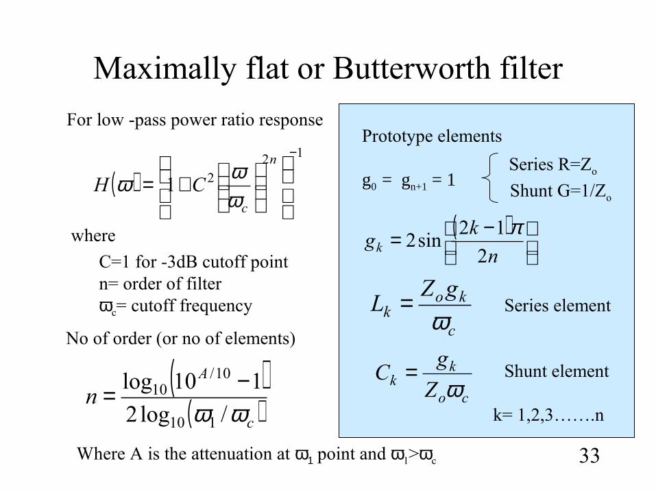
Maximally flat or Butterworth filter
33
( )12
21
−
+=
n
c
CHωωω
For low -pass power ratio response
( )
−=
n
kgk 2
12sin2
π
g0 = gn+1 = 1
( )( )cA
nωω /log2
110log
110
10/10 −= co
kk Z
gC
ω=
c
kok
gZL
ω=
where
C=1 for -3dB cutoff pointn= order of filter ωc= cutoff frequency
No of order (or no of elements)
Where A is the attenuation at ω1 point and ω1>ωc
Prototype elements
k= 1,2,3…….n
Series element
Shunt element
Series R=Zo
Shunt G=1/Zo
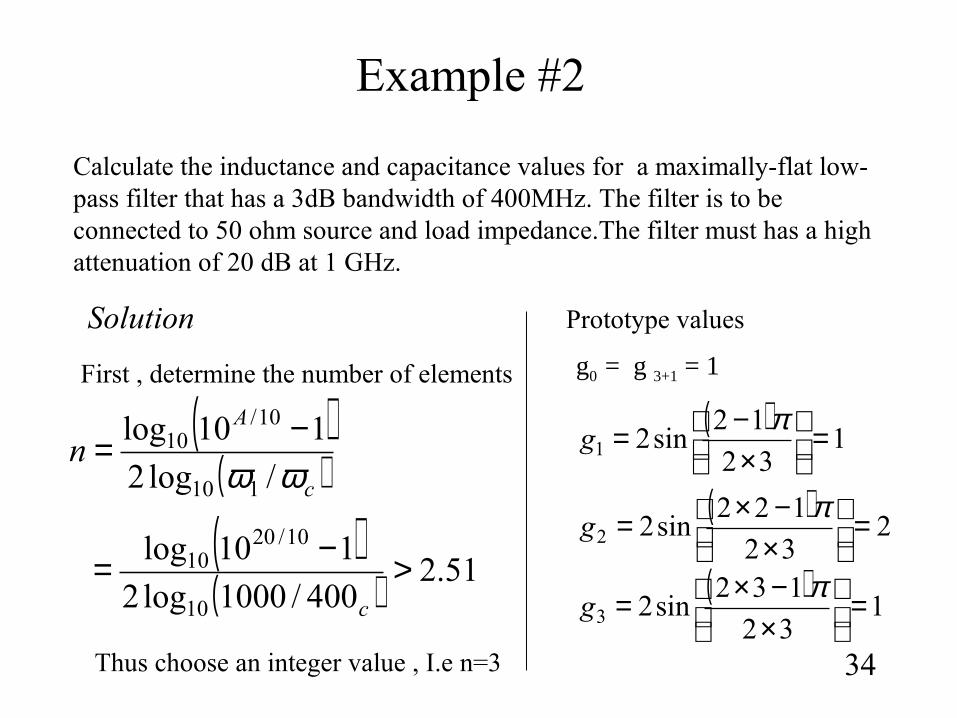
Example #2
34
Calculate the inductance and capacitance values for a maximally-flat low-pass filter that has a 3dB bandwidth of 400MHz. The filter is to be connected to 50 ohm source and load impedance.The filter must has a high attenuation of 20 dB at 1 GHz.
( )( )cA
nωω /log2
110log
110
10/10 −=
( )1
32
12sin21 =
×−= π
g
g0 = g 3+1 = 1First , determine the number of elements
Solution
( )( ) 51.2
400/1000log2
110log
10
10/2010 >−=
c
Thus choose an integer value , I.e n=3
Prototype values
( )2
32
122sin22 =
×−×= π
g
( )1
32
132sin23 =
×−×= π
g
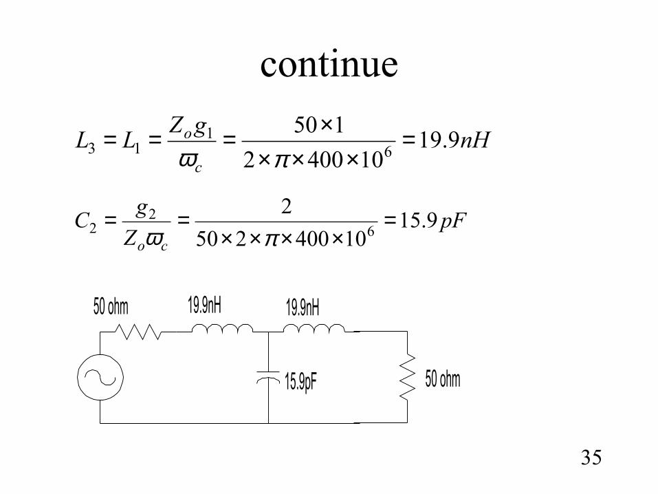
continue
35
nHgZ
LLc
o 9.19104002
1506
113 =
××××===
πω
pFZ
gC
co
9.1510400250
26
22 =
××××==
πω
15.9pF
19.9nH
50 ohm
50 ohm 19.9nH
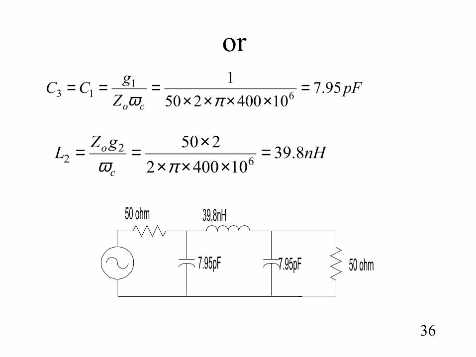
or
36
nHgZ
Lc
o 8.39104002
2506
22 =
××××==
πω
pFZ
gCC
co
95.710400250
16
113 =
××××===
πω
7.95pF
39.8nH
50 ohm
50 ohm
7.95pF
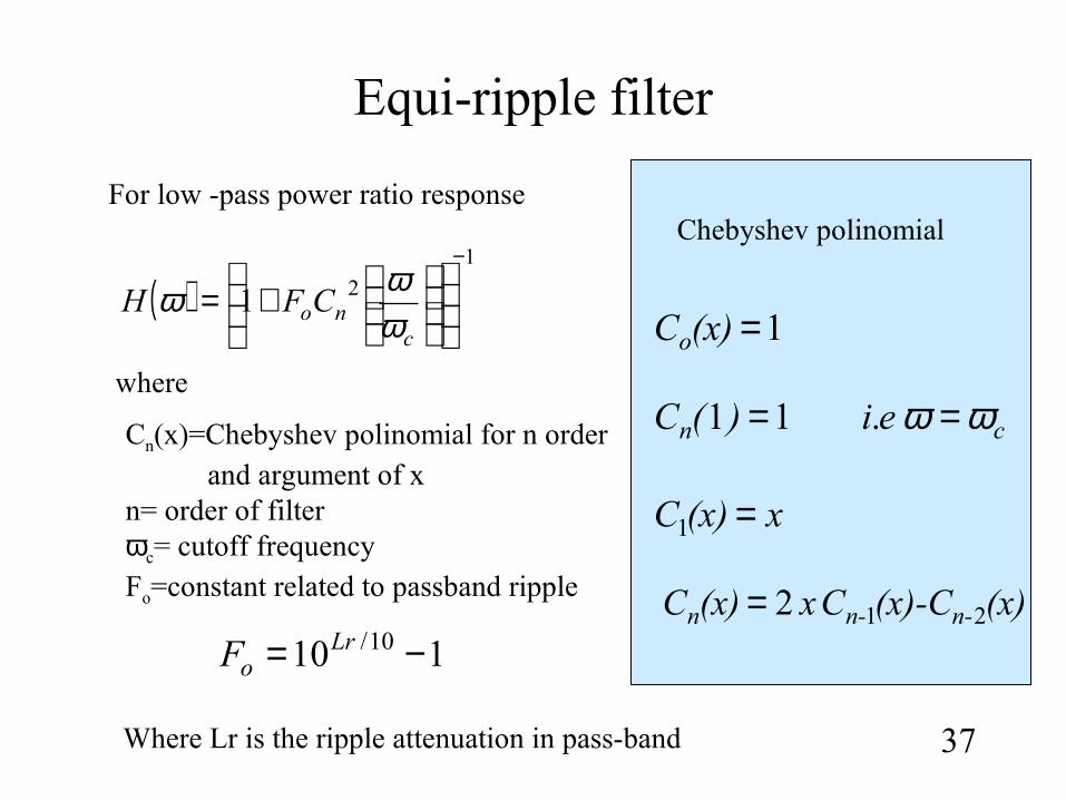
Equi-ripple filter
37
( )1
21
−
+=
cnoCFH
ωωω
For low -pass power ratio response
110 10/ −= LroF
where
Cn(x)=Chebyshev polinomial for n order and argument of x n= order of filter ωc= cutoff frequencyFo=constant related to passband ripple
Chebyshev polinomial
Where Lr is the ripple attenuation in pass-band
(x)(x)-CCx(x)C n-n-n 212=
x(x)C =1
cn ei)(C ωω == .11
1=(x)Co
Continue
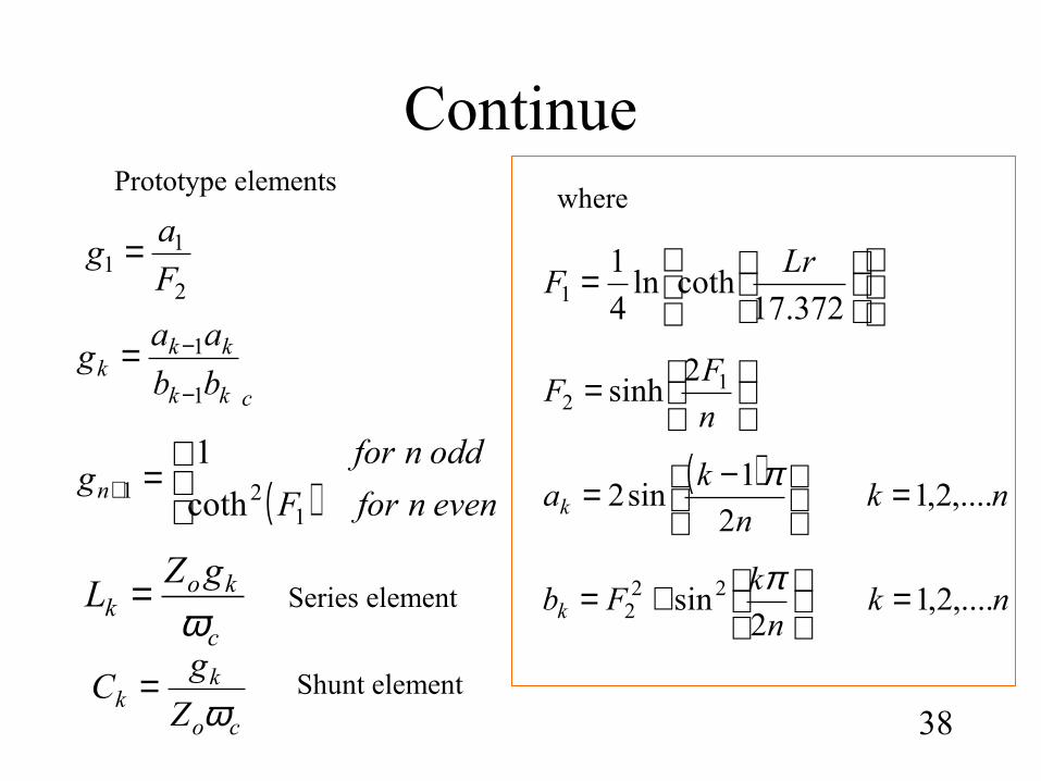
38
Prototype elements
=
372.17cothln
4
11
LrF
( )
=+ evennforF
oddnforgn
121 coth
1
ckk
kkk bb
aag
1
1
−
−=
2
11 F
ag =
where
=n
FF 1
22
sinh
( )nk
n
kak ,....2,1
2
1sin2 =
−= π
nkn
kFbk ,....2,1
2sin22
2 =
+= π
c
kok
gZL
ω=
co
kk Z
gC
ω=
Series element
Shunt element
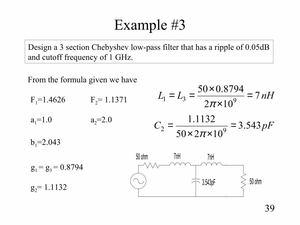
Example #3
39
Design a 3 section Chebyshev low-pass filter that has a ripple of 0.05dB and cutoff frequency of 1 GHz.
From the formula given we have
g2= 1.1132
g1 = g3 = 0.8794
F1=1.4626 F2= 1.1371
a1=1.0 a2=2.0
b1=2.043
nHLL 7102
8794.050931 =
××==π
pFC 543.310250
1132.192 =
××=
π
3.543pF
7nH
50 ohm
50 ohm 7nH
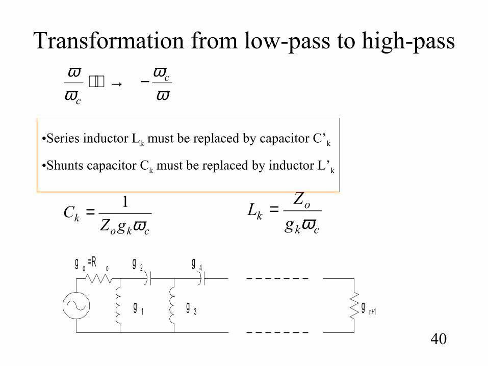
Transformation from low-pass to high-pass
40
•Series inductor Lk must be replaced by capacitor C’k
•Shunts capacitor Ck must be replaced by inductor L’k
ck
ok g
ZL
ω=
ckok gZC
ω1=
ωω
ωω c
c
−→
g o =R o
g 1
g 2
g 3
g 4
g n+1
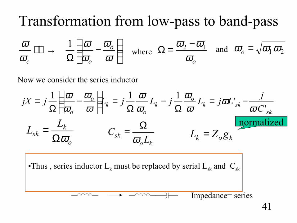
Transformation from low-pass to band-pass
41
•Thus , series inductor Lk must be replaced by serial Lsk and Csk
o
ksk
LL
ωΩ=
kosk LC
ωΩ=
−
Ω→
ωω
ωω
ωω o
oc
1where
oωωω 12 −=Ω 21 ωωω =oand
skskk
ok
ok
o
o C
jLjLjLjLjjX
''
111
ωω
ωω
ωω
ωω
ωω −=
Ω−
Ω=
−
Ω=
Now we consider the series inductor
kok gZL =
Impedance= series
normalized
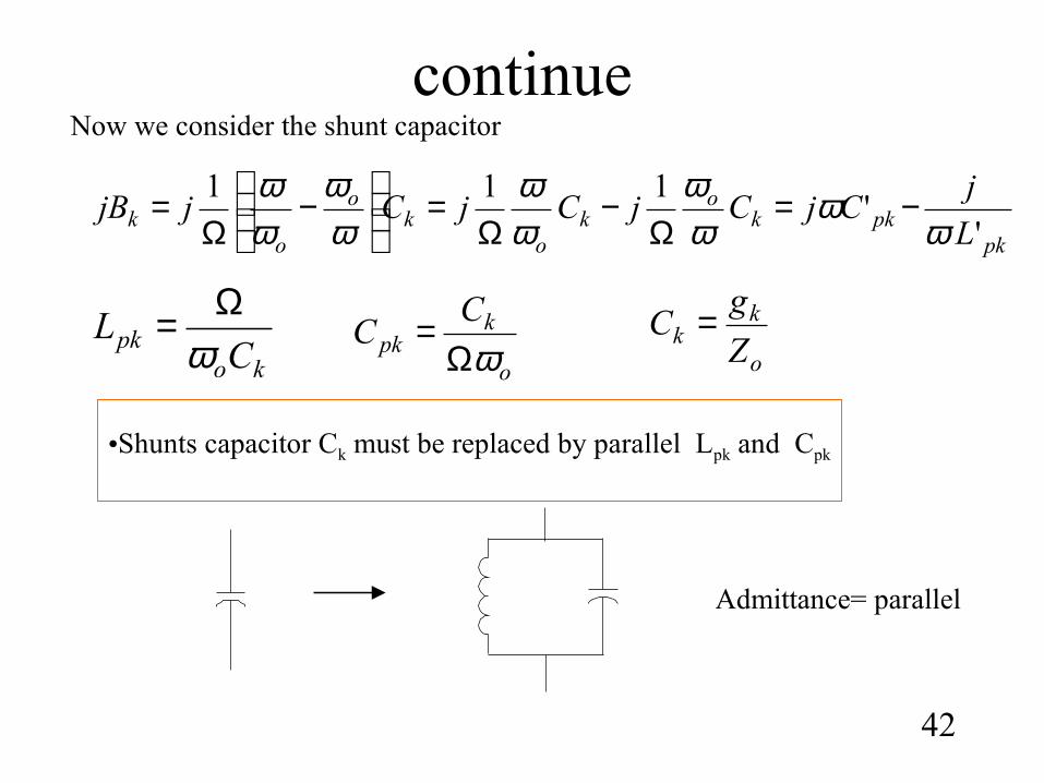
continue
42
•Shunts capacitor Ck must be replaced by parallel Lpk and Cpk
kopk CL
ωΩ=
o
kpk
CC
ωΩ=
pkpkk
ok
ok
o
ok L
jCjCjCjCjjB
''
111
ωω
ωω
ωω
ωω
ωω −=
Ω−
Ω=
−
Ω=
Now we consider the shunt capacitor
o
kk Z
gC =
Admittance= parallel
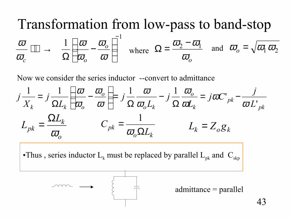
Transformation from low-pass to band-stop
43
•Thus , series inductor Lk must be replaced by parallel Lpk and Cskp
o
kpk
LL
ωΩ=
kopk L
CΩ
=ω
1
11
−
−
Ω→
ωω
ωω
ωω o
ocwhere
oωωω 12 −=Ω 21 ωωω =oand
pkpk
k
o
ko
o
okk L
jCj
Lj
Lj
Lj
Xj
''
1111
ωω
ωω
ωω
ωω
ωω −=
Ω−
Ω=
−
Ω=
Now we consider the series inductor --convert to admittance
kok gZL =
admittance = parallel
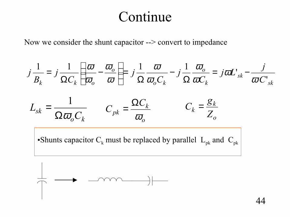
Continue
44
•Shunts capacitor Ck must be replaced by parallel Lpk and Cpk
kosk CL
ωΩ= 1
o
kpk
CC
ωΩ=
sksk
k
o
ko
o
okk C
jLj
Cj
Cj
Cj
Bj
''
1111
ωω
ωω
ωω
ωω
ωω −=
Ω−
Ω=
−
Ω=
Now we consider the shunt capacitor --> convert to impedance
o
kk Z
gC =
Example #4
45
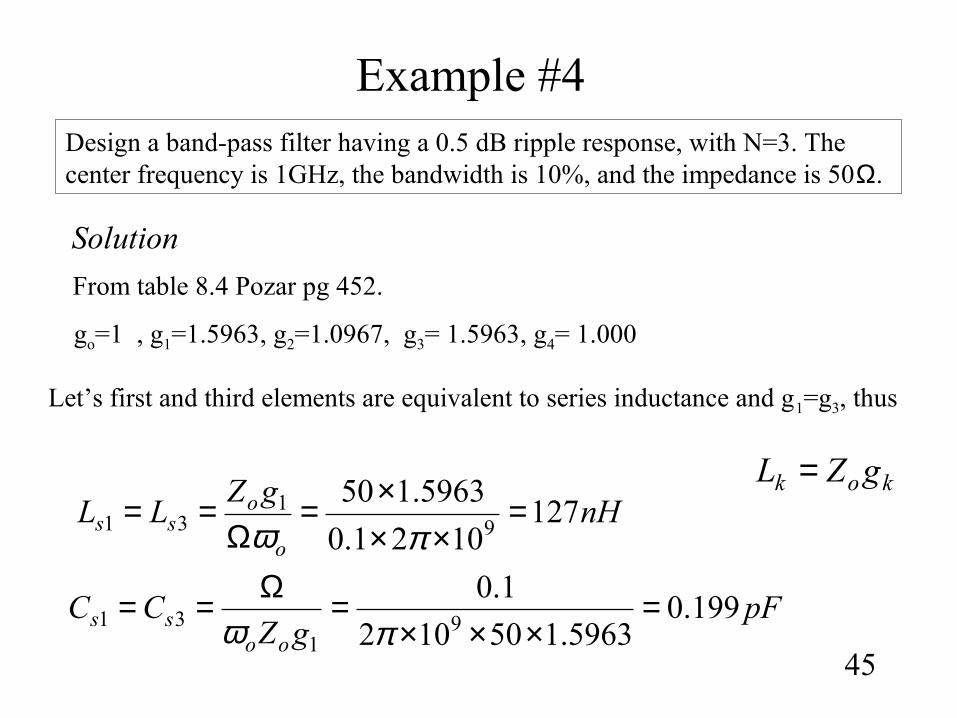
Design a band-pass filter having a 0.5 dB ripple response, with N=3. The center frequency is 1GHz, the bandwidth is 10%, and the impedance is 50Ω.
Solution
From table 8.4 Pozar pg 452.
go=1 , g1=1.5963, g2=1.0967, g3= 1.5963, g4= 1.000
Let’s first and third elements are equivalent to series inductance and g1=g3, thus
nHgZ
LLo
oss 127
1021.0
5963.1509
131 =
×××=
Ω==
πω
pFgZ
CCoo
ss 199.05963.150102
1.09
131 =
×××=Ω==
πω
kok gZL =
continue
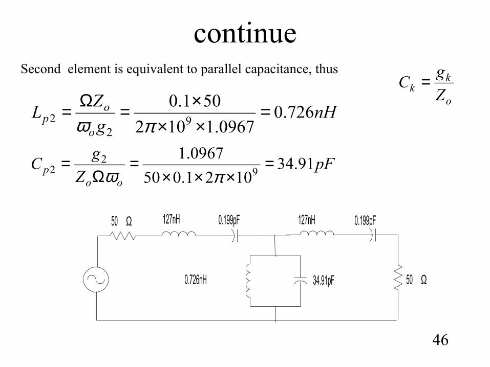
46
Second element is equivalent to parallel capacitance, thus
nHg
ZL
o
op 726.0
0967.1102
501.09
22 =
×××=Ω=
πω
pFZ
gC
oop 91.34
1021.050
0967.19
22 =
×××=
Ω=
πω
o
kk Z
gC =
50 Ω 127nH 0.199pF
0.726nH 34.91pF
127nH 0.199pF
50 Ω
Implementation in microstripline
47
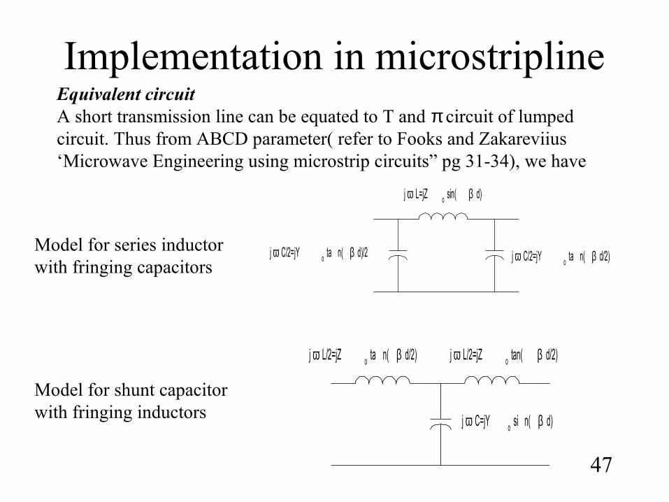
Equivalent circuitA short transmission line can be equated to T and π circuit of lumped circuit. Thus from ABCD parameter( refer to Fooks and Zakareviius ‘Microwave Engineering using microstrip circuits” pg 31-34), we have
j ω L=jZ o sin( β d)
j ω C/2=jY o ta n( β d)/2 j ω C/2=jY o ta n( β d/2)
j ω L/2=jZ o tan( β d/2)j ω L/2=jZ o ta n( β d/2)
j ω C=jY o si n( β d)
Model for series inductor with fringing capacitors
Model for shunt capacitor with fringing inductors
48
d
Z o
L
Z oL
Z o
=
d
oCfC
dZL
λπ
ωtan
=
doLfL
d
ZC
λπ
ωtan
1
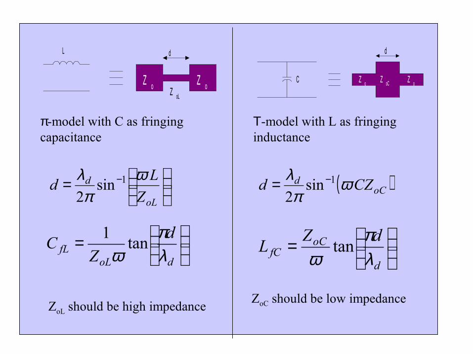
π-model with C as fringing capacitance
Τ-model with L as fringing inductance
ZoL should be high impedanceZoC should be low impedance
d
Z oZ oCC Z o
= −
oL
d
Z
Ld
ωπ
λ 1sin2
( )oCd CZd ωπ
λ 1sin2
−=
Example #5
49
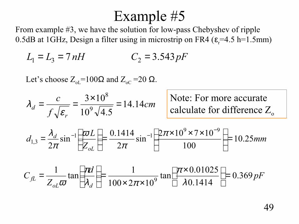
From example #3, we have the solution for low-pass Chebyshev of ripple 0.5dB at 1GHz, Design a filter using in microstrip on FR4 (εr=4.5 h=1.5mm)
nHLL 731 == pFC 543.32 =
Let’s choose ZoL=100Ω and ZoC =20 Ω.
mmZ
Ld
oL
d 25.10100
107102sin
2
1414.0sin
2
9911
3,1 =
×××=
=
−−− π
πω
πλ
cmf
c
rd 14.14
5.410
1039
8
=×==ε
λ
pFd
ZC
doLfL 369.0
1414.0
01025.0tan
102100
1tan
19
=
×
××=
=
λπ
πλπ
ω
Note: For more accurate calculate for difference Zo
continue
50
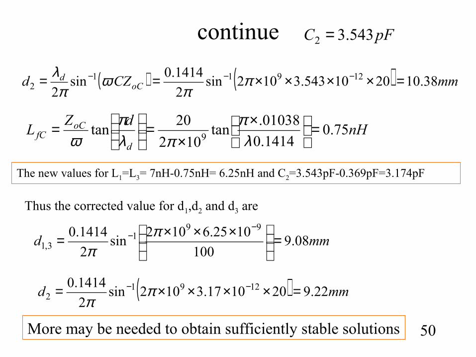
( ) ( ) mmCZd oCd 38.102010543.3102sin
2
1414.0sin
212911
2 =××××== −−− ππ
ωπ
λ
nHdZ
Ld
oCfC 75.0
1414.0
01038.tan
102
20tan
9=
×
×=
=
λπ
πλπ
ω
pFC 543.32 =
The new values for L1=L3= 7nH-0.75nH= 6.25nH and C2=3.543pF-0.369pF=3.174pF
Thus the corrected value for d1,d2 and d3 are
mmd 08.9100
1025.6102sin
2
1414.0 991
3,1 =
×××=−
− ππ
( ) mmd 22.9201017.3102sin2
1414.0 12912 =××××= −− π
π
More may be needed to obtain sufficiently stable solutions
51
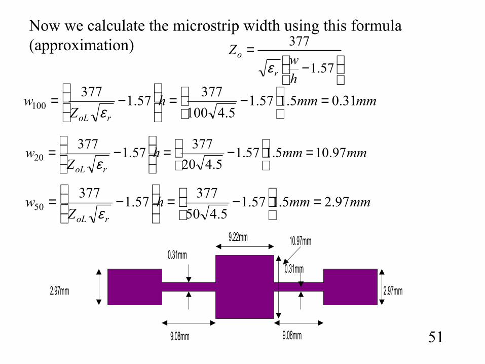
mmmmhZ
wroL
31.05.157.15.4100
37757.1
377100 =
−=
−=
ε
mmmmhZ
wroL
97.105.157.15.420
37757.1
37720 =
−=
−=
ε
−
=57.1
377
hw
Z
r
o
ε
Now we calculate the microstrip width using this formula (approximation)
mmmmhZ
wroL
97.25.157.15.450
37757.1
37750 =
−=
−=
ε
10.97mm
2.97mm
0.31mm
9.08mm
9.22mm
9.08mm
2.97mm
0.31mm
Implementation using stub
52
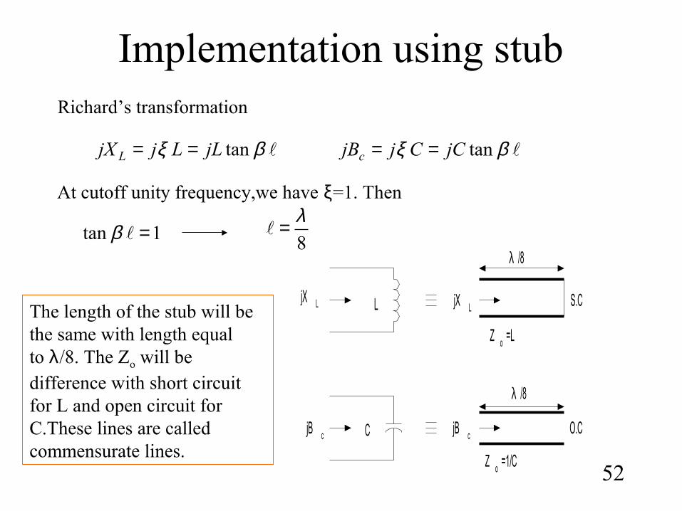
Richard’s transformation
βξ tanjLLjjX L == βξ tanjCCjjBc ==
At cutoff unity frequency,we have ξ=1. Then
1tan =β 8
λ=
L
C
jX L
jB c
λ /8
S.C
O.C
Z o =L
Z o =1/C
jX L
jB c
λ /8
The length of the stub will be the same with length equal to λ/8. The Zo will be difference with short circuit for L and open circuit for C.These lines are called commensurate lines.
Kuroda identity
53
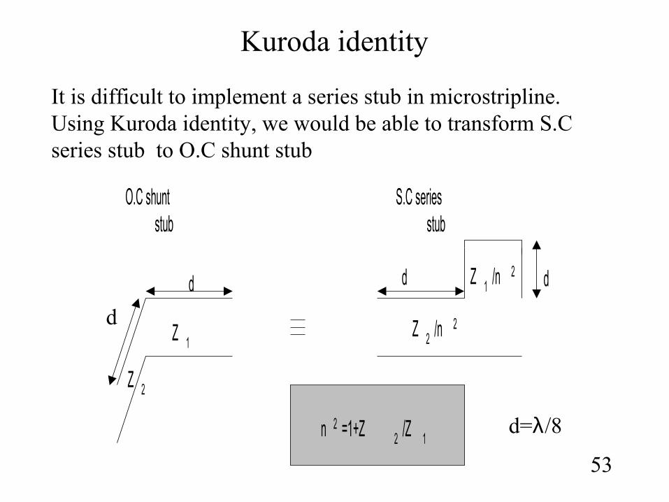
It is difficult to implement a series stub in microstripline. Using Kuroda identity, we would be able to transform S.C series stub to O.C shunt stub
d
d d d
S.C seriesstub
O.C shuntstub
Z 1Z 2 /n 2
n 2 =1+Z 2 /Z 1
Z 1 /n 2
Z 2
d=λ/8
Example #6
54
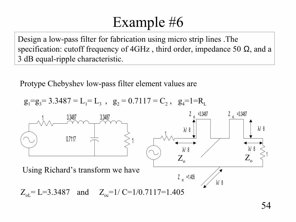
Design a low-pass filter for fabrication using micro strip lines .The specification: cutoff frequency of 4GHz , third order, impedance 50 Ω, and a 3 dB equal-ripple characteristic.
Protype Chebyshev low-pass filter element values are
g1=g3= 3.3487 = L1= L3 , g2 = 0.7117 = C2 , g4=1=RL
1
1 3.3487
0.7117
3.3487
Using Richard’s transform we have
ZoL= L=3.3487 Zoc=1/ C=1/0.7117=1.405and
1λ/ 8
1λ/ 8
λ/ 8
λ/ 8
λ/ 8
Z oc =1.405
Z oL =3.3487Z oL =3.3487
Zo Zo
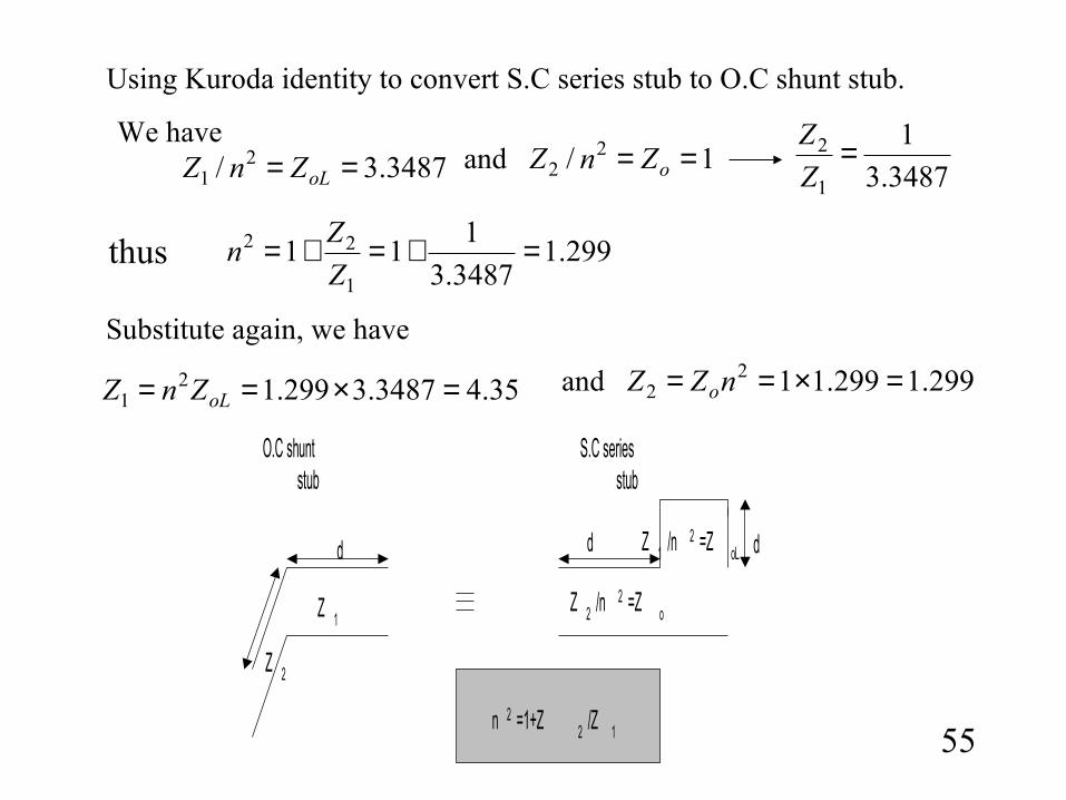
Using Kuroda identity to convert S.C series stub to O.C shunt stub.
299.13487.3
111
1
22 =+=+=Z
Zn
3487.3
1
1
2 =Z
Z3487.3/ 2
1 == oLZnZ 1/ 22 == oZnZ
thus
We haveand
Substitute again, we have
35.43487.3299.121 =×== oLZnZ 299.1299.112
2 =×== nZZ oand
55
d d d
S.C seriesstub
O.C shuntstub
Z 1Z 2 /n 2 =Z o
n 2 =1+Z 2 /Z 1
Z 1 /n 2 =Z oL
Z 2
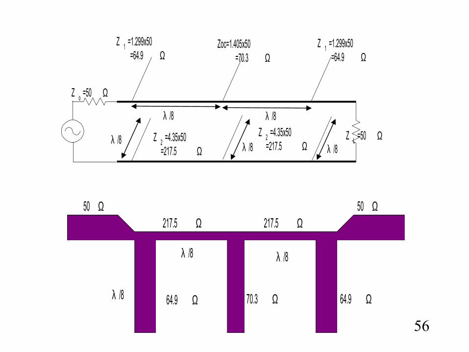
50 Ω217.5 Ω
64.9 Ω 70.3 Ω
λ /8
64.9 Ωλ /8
λ /8
217.5 Ω50 Ω
56
λ /8
λ /8λ /8 λ /8
λ /8
Z o =50 Ω
Z 2 =4.35x50=217.5 Ω
Z 1 =1.299x50=64.9 Ω
Zoc=1.405x50=70.3 Ω
Z L =50 Ω
Z 1 =1.299x50=64.9 Ω
Z 2 =4.35x50=217.5 Ω
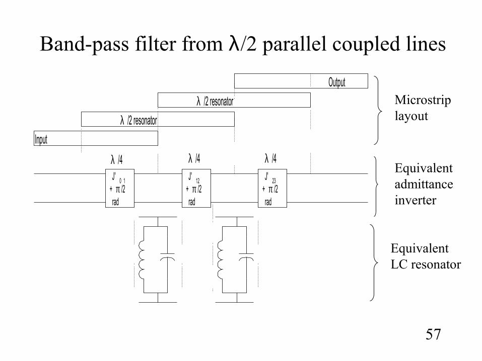
Band-pass filter from λ/2 parallel coupled lines
57
Input
λ /2 resonator
λ /2 resonator
Output
J' 0 1+ π /2rad
J' 23+ π /2rad
J' 12+ π /2rad
λ /4 λ /4λ /4
Microstrip layout
Equivalent admittance inverter
Equivalent LC resonator
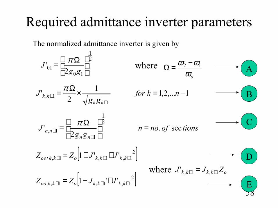
Required admittance inverter parameters
58
21
1001 2'
Ω=
ggJ
π
1,...2,11
2'
11, −=×Ω=
++ nkfor
ggJ
kkkk
π
tionsofnongg
Jnn
nn sec.2
'21
11, =
Ω=
++
π
oωωω 12 −=Ω
The normalized admittance inverter is given by
[ ]21,1,1, ''1, +++ ++= kkkkokkoe JJZZ
[ ]21,1,1,, ''1 +++ +−= kkkkokkoo JJZZ
okkkk ZJJ 1,1,' ++ =where
where A
B
C
D
E
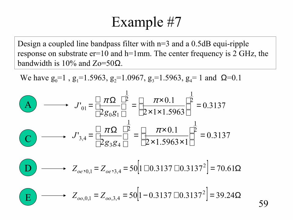
Example #7
59
Design a coupled line bandpass filter with n=3 and a 0.5dB equi-ripple response on substrate er=10 and h=1mm. The center frequency is 2 GHz, the bandwidth is 10% and Zo=50Ω.
We have g0=1 , g1=1.5963, g2=1.0967, g3=1.5963, g4= 1 and Ω=0.1
3137.05963.112
1.0
2'
21
21
1001 =
×××=
Ω= ππ
ggJ
[ ] Ω=++== 61.703137.03137.0150,, 24,31,0 oeoe ZZ
[ ] Ω=+−== 24.393137.03137.0150 24,3,1,0, oooo ZZ
3137.015963.12
1.0
2'
21
21
434,3 =
×××=
Ω= ππ
ggJ
A
C
D
E
60
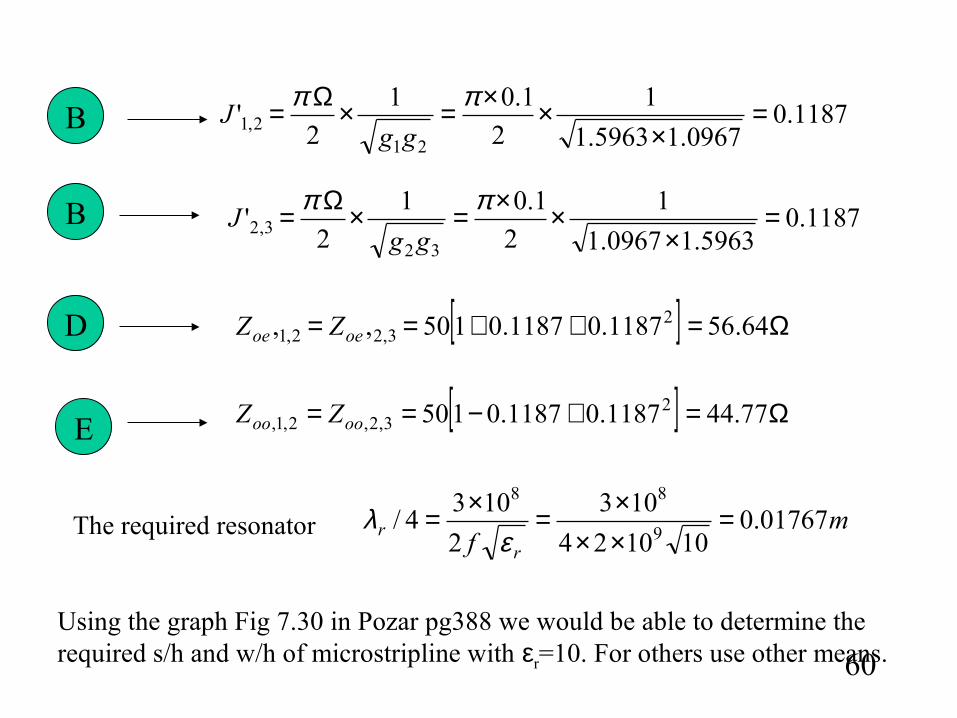
1187.00967.15963.1
1
2
1.01
2'
212,1 =
×××=×Ω= ππ
ggJ
1187.05963.10967.1
1
2
1.01
2'
323,2 =
×××=×Ω= ππ
ggJB
B
[ ] Ω=++== 64.561187.01187.0150,, 23,22,1 oeoe ZZ
[ ] Ω=+−== 77.441187.01187.0150 23,2,2,1, oooo ZZ
D
E
Using the graph Fig 7.30 in Pozar pg388 we would be able to determine the required s/h and w/h of microstripline with εr=10. For others use other means.
mf r
r 01767.0101024
103
2
1034/
9
88
=×××=×=
ελThe required resonator
61
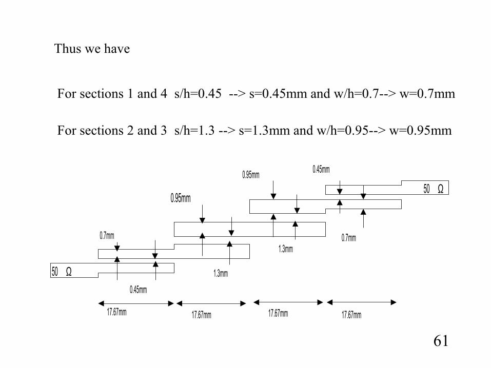
Thus we have
For sections 1 and 4 s/h=0.45 --> s=0.45mm and w/h=0.7--> w=0.7mm
For sections 2 and 3 s/h=1.3 --> s=1.3mm and w/h=0.95--> w=0.95mm
50 Ω
50 Ω
0.7mm
0.45mm
0.95mm
1.3mm
0.95mm
1.3mm
0.45mm
0.7mm
17.67mm 17.67mm 17.67mm 17.67mm
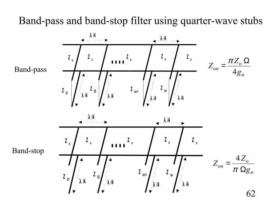
Band-pass and band-stop filter using quarter-wave stubs
62
n
oon g
ZZ
4
Ω= π
n
oon g
ZZ
Ω=
π4
Band-pass
Band-stop
....Z 01
Z 02 Z on-1Z on
Z oZ oZ oZ o
Z o
λ /4
λ /4λ /4λ /4λ /4
λ /4
....Z 01
Z 02Z on-1 Z on
Z oZ oZ oZ o
Z o
λ /4
λ /4λ /4λ /4λ /4
λ /4
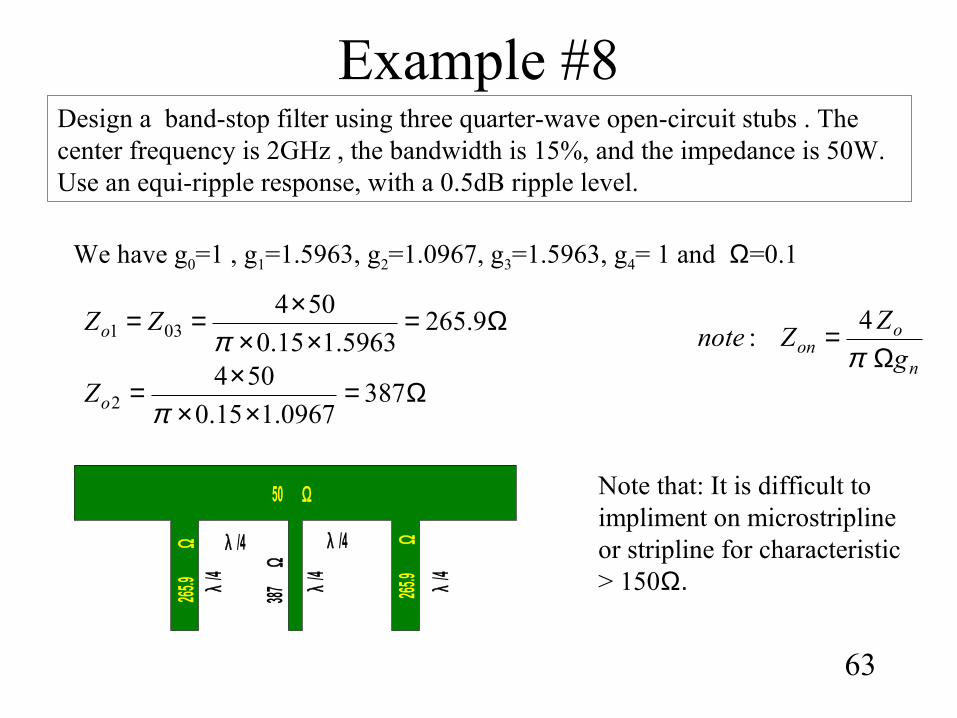
Example #8
63
Design a band-stop filter using three quarter-wave open-circuit stubs . The center frequency is 2GHz , the bandwidth is 15%, and the impedance is 50W. Use an equi-ripple response, with a 0.5dB ripple level.
We have g0=1 , g1=1.5963, g2=1.0967, g3=1.5963, g4= 1 and Ω=0.1
n
oon g
ZZnote
Ω=
π4
:Ω=
×××== 9.265
5963.115.0
504031 πZZo
Ω=××
×= 3870967.115.0
5042 πoZ
50 Ω
λ /4
265.9
Ω
387Ω
265.9
Ω λ /4
λ/4
λ/4
λ/4
Note that: It is difficult to impliment on microstripline or stripline for characteristic > 150Ω.
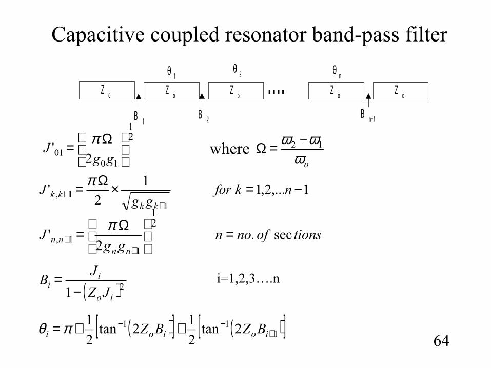
Capacitive coupled resonator band-pass filter
64
Z o Z oZ oZ o ....B 2B 1
θ 2θ 1
B n+1
Z o
θ n
21
1001 2'
Ω=
ggJ
π
1,...2,11
2'
11, −=×Ω=
++ nkfor
ggJ
kkkk
π
tionsofnongg
Jnn
nn sec.2
'21
11, =
Ω=
++
π
oωωω 12 −=Ωwhere
( ) 21 io
ii
JZ
JB
−=
( )[ ] ( )[ ]111 2tan
2
12tan
2
1+
−− ++= ioioi BZBZπθ
i=1,2,3….n
Example #9
65
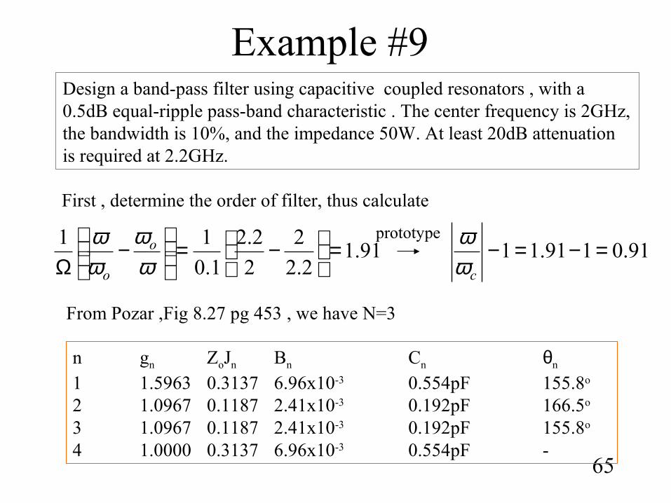
Design a band-pass filter using capacitive coupled resonators , with a 0.5dB equal-ripple pass-band characteristic . The center frequency is 2GHz, the bandwidth is 10%, and the impedance 50W. At least 20dB attenuation is required at 2.2GHz.
First , determine the order of filter, thus calculate
91.12.2
2
2
2.2
1.0
11 =
−=
−
Ω ωω
ωω o
o
91.0191.11 =−=−cω
ω
From Pozar ,Fig 8.27 pg 453 , we have N=3
prototype
n gn ZoJn Bn Cn θn
1 1.5963 0.3137 6.96x10⁻³ 0.554pF 155.8o
2 1.0967 0.1187 2.41x10⁻³ 0.192pF 166.5o
3 1.0967 0.1187 2.41x10⁻³ 0.192pF 155.8o
4 1.0000 0.3137 6.96x10⁻³ 0.554pF -
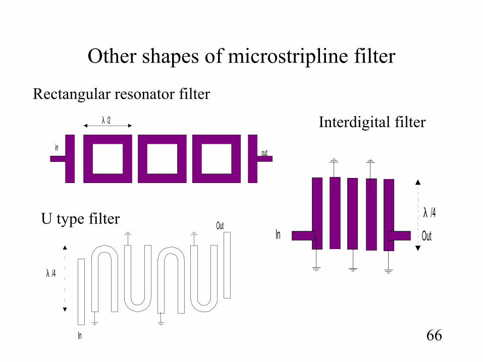
Other shapes of microstripline filter
66
Rectangular resonator filter
U type filter
λ /4
In
Outλ /4
In Out
Interdigital filterλ /2
inout
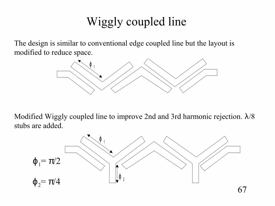
Wiggly coupled line
ϕ 1
ϕ 2
67
ϕ1= π/2
ϕ2= π/4
The design is similar to conventional edge coupled line but the layout is modified to reduce space.
ϕ 1
Modified Wiggly coupled line to improve 2nd and 3rd harmonic rejection. λ/8 stubs are added.