finite element simulations for entropy generation
TRANSCRIPT

Finite Element Simulations for Entropy GenerationMeasurement in Single Phase Flow of Water BasedNano�uid Filled in Square Cavity under Appliance ofInclined Magnetic �eldS. Bilal ( [email protected] )
Air University
Research Article
Keywords: Entropy generation, Finite element method, Magnetic �eld, Single phase nano �uid, Squarecavity
Posted Date: February 16th, 2021
DOI: https://doi.org/10.21203/rs.3.rs-151378/v1
License: This work is licensed under a Creative Commons Attribution 4.0 International License. Read Full License

Finite Element Simulations for Entropy Generation Measurement in Single
Phase Flow of Water Based Nanofluid Filled in Square Cavity under
Appliance of Inclined Magnetic field
1*S. Bilal
1Department of Mathematics, Air University, Islamabad, 44000, Pakistan
* 1*Corresponding Author: S. Bilal, Email: [email protected]
Abstract: Current communication candidly explicates entropy generation process
generated due to natural convective heating in square enclosure saturated with
nanofluid. Water is used as base fluid and Cu particles are induced to depict
enhancement in thermo physical characteristics. Natural convection in enclosure is
produced by providing temperature difference on boundaries. Upper wall is
provided uniform temperature while rest of walls are kept cold. Impermeability and
non-slip conditions are imposed on all walls. Mathematical structuring of
considered problem is manifested via continuity, momentum and energy equations
under appliance of inclined magnetic field. Thermo physical properties of
nanoparticles along with base liquids are used during mathematical structuring.
Finite element procedure is adopted to elucidate flow features. Discretization of
domain is done by applying hybrid meshing. Velocity and isothermal plots are
drawn against concerning parameters. Comprehensive description of energy
generation by measuring variation in magnetic, viscous, total and thermal
irreversibility’s are also presented. Cut lines representing velocity field in
horizontal and vertical direction are also drawn to predict flow behavior at different
locations.
Keywords: Entropy generation; Finite element method; Magnetic field; Single
phase nano fluid; Square cavity
1 Introduction
Entropy is the intrinsic property of every thermo dynamical system which measures randomness
generated due to irreversibility process during thermal energy exchange. Measurement about
entropy in thermalized systems is consequence of second thermo dynamical law [1] which relates
that amount of total entropy persist uniformly for reversible processes while for irreversible
procedures it increases with time. Clausius [2] was one of the foremost responsible for the
development regarding thermo mechanic theory about irreversible processes and introduced the
concept of entropy. Bejan [3] was among the foremost one who initially deliberated entropy
generation rate by formulating method of thermodynamical optimization. Aiming at the
optimization of architecture and better performance of thermo hydraulic systems entropy
generation processes are applied to numerous conventional industrial structures. In addition
entropy analysis is an influential way to uplift efficiency of heat devices likewise in, heat engine,
heat pump, refrigerators, high temperature semiconductors, electronic chips cooling systems,

2
micro heating channels. On overviewing the essence of entropy generation for measuring thermo
dynamical irreversibility’s in numerous designs researchers have shown pervasive interest. For example, Kefayati et al. [4] explicated entropy generation in convective flow of nano liquid in an
inclining enclosure by implementing LBM. They found that with inclusion of entropy aspects a
dimensionless Bejan number is modelled in mathematical formulation. They also disclosed that
Bejan number has inverse relation with entropic variations. Parvin et al. [5] measured entropic
irreversibility produced in water saturated in odd shaped enclosure with induction of metallic
nanoparticles. They revealed influential role of natural convection on entropy variation by
expressing relation between Rayleigh and Bejan numbers. Merji et al. [6] and Mahmoudi et al. [7]
computationally analyzed execution of entropy in square enclosure embedded with water with
fusion of hybridized nanoparticles. They interpreted impression of nanoparticle volume fraction
on accumulative entropy process. Armaghani et al. [8] probed features of entropy generation in
baffled L-shaped enclosure saturated by water under provision of buoyantly convective thermal
differentiated to flow domain along with inclusion of alumina nanoparticles. Zamily et al. [9]
studied thermo physical features of water along with addition of Ti𝑂2 particles along with checking
variation in entropy randomness by locating heat sources at boundaries in cavity. Bouchouch et al.
[10] examined irreversibility in nanofluid (𝐻2𝑂/𝐴𝑙2𝑂3) flow in symmetric enclosure by providing
non-isothermal heating through introduction of sinusoidal input. They concluded that entropy
diffuses in system more quickly and significantly with consideration of free convection
environment. Ashornejad et al. [11] depicted randomness generated among particles of water
capitalized as host fluid with insertion of different nature nano sized particles in permeable square
cavity. They found that dispersion of solid particles raises entropy change and enhances heat
transfer. Sheremet et al. [12] deliberated heat transfer formed due to entropic change in water based
nanofluid inside square enclosure by transferring variable wall temperature. Alsabery et al. [13]
irreversibility aspects in hybridized nanofluid flow comprising of water as host liquids and alumina
as suspended constituents by inserting solid concentric cylinders. They disclosed that significant
change appears in entropy with enhancement in Rayleigh number (Ra) which measures dominancy
of natural convection. Siavashi et al. [14] capitalized two phase mixture of water and copper
particles to quantify entropic feature in free convective flow inside permeable enclosure furnished
with fins. Kashyap et al. [15] studied two-phase (water/Cu) flow of nanofluid along with execution
of entropy in permeable square cavity governed by Brickman-Darcy model under the restriction
of different boundary conditions. Analysis about thermo physical characteristics due to entropy
generated in nano liquid in lid driven cavity was manifested by Gibanov et al. [16]. Mansour et al.
[17] inspected entropy in hybridized nanofluid (water-Cu-𝐴𝑙2𝑂3) in square permeable enclosure
under appliance of magnetization. They revealed that nanoparticle volume fraction causes
increment in entropy. Rahimi et al. [18] considered thermal aspects of entropy process in (water–CuO) nanofluid inside enclosure furnished with fins and estimated decreases in generated entropy
against fractional volume of nanoparticles. Rashidi et al. [19] conducted detailed comparative
analysis for entropy in symmetrical heat exchanger. Some recently significant disquisitions on
entropy process have been carried out in [20-26].
Nanofluids are shattered suspensions of nano scaled particles in the form of nanotubes, nanofibers
and droplets and inducted to raise thermal conductivity of ordinary liquids. From the arrival of
nanomechanics, nanoliquids becomes under observation due to their intrinsic eccentric attributes.
These characteristics have made them proficient in medicinal processes, hybridized engines, fuel
cells, microelectronics and in most fields of nanotechnologies [27-28]. Initially, in 1995 Choi [29]
disclosed reference of nanofluids as suspension in base fluid. An extensive overview about

3
nanoliquids is available like Eastman et al. [30] experimentally discussed uplift in thermal
conductivity of host fluid with particles suspended by Choi in study referred in [29]. Specifically,
researchers are working on enclosed thermally conducted systems due to their extensive practical
utility. Likewise, Ahmed et al. [31] adumbrated thermal dispersion of nanoparticles in single phase
liquid saturated in lid driven cavity by finite volume scheme. Sheikholeslami and his collaborators
[32-33] have shown significance of nanotechnology by examining possessions and properties with
usage of different approaches. Yadav et al. [34] have investigated the onset of magnetized
nanofluid by finding numerical simulations for heat transfer enhancement along with stability of
nanofluid particles in linear and non-linear way. Khan et al. [35] considered constructal Y shaped
design to report thermal control and uplift in split lid driven cavity by implementing finite element
analysis. Few though provoking investigations related to nanoliquids are enclosed in [36-41].
Analysis about heat transfer characteristics in convective flow generated by temperature gradient
in enclosed domains has intended considerable attention due to gaining significant physical
importance. This is their competence to resolve wide applicable processes in geological reservoirs,
thermally insulated systems, filtration processes, nuclear waste storing, solidification of castings,
liquefaction gases, biofilm growth and so forth. Poulikatos et al. [42] derived actual source for
generation of natural convection in flow domain i.e. gravity aspects and also determined different
ranges about Rayleigh number which controls convection process. Beckermann et al. [43] probed
naturally convective flow inside rectangular cavity. Chen and Cheng [44] achieved computational
analysis on free convection in an inclining arc shaped enclosure. November and Nansteel [45]
adumbrated free convective flow by prescribing different temperatures at boundaries of domain.
For interest of readers few recent studies of natural convection heat phenomenon in different shape
enclosures under multiple physical conditions are collected in [46-53].
In present disquisition the author has restricted attention towards explication of entropy generation
process by providing inclined magnetic field induction along with inclusion of natural convection
process. In this pagination an extensive variation in different types of irreversibility’s will be discussed against different effective parameters which is not revealed yet. So, it is hope that this
work will serve as referenced study for upcoming research in this direction.
2 Mathematical modelling
We have assumed square cavity of unit dimensions saturated by water along with induction of
copper nanoparticles. Density variations in flow domain is included by incorporation of buoyancy
term represented by Boussinesq approximation which incorporates the role of natural convection
in flow domain. Constant magnetization of magnitude 𝐵𝑜 is employed in orthogonal direction to
measure maximum change in nanoparticles flow. Upper wall of enclosure is considered to be
uniformly heated whereas rest of walls are in colder situation. All the boundaries are at no-slip
condition. Physical configuration is exemplified in figure 1.

4
Fig. 1 Physical structuring of problem.
Governing expressions are as follows
0, u v
x y
+ =
(1)
2 2
2 2
2 2Pr Ha sin cos sin ,
nf nf
f
nf f f
u u u pu v
x y x
u uv u
x y
+ + + =
+ + −
(2)
( )
2 2
2 2
2 2Pr Pr Ha sin cos cos ,
nf
nf f
nf nf
f f f
nf f f
v v v p v vu v
x y y x y
Ra T u v
+ + + = +
+ + −
(3)
2 2
2 2
nf
f
T T T T Tu v
x y x y
+ + = +
(4)
Thermo physical features concerning to capitalized nanofluid are given respectively
( )1 , nf f s = − + (5)
( ) ( )( ) ( )1 , nf f s
= − + (6)
( ) ( )( ) ( )1 , p p pnf f sc c c = − + (7)
Brickman model for viscosity is utilized represented as follows

5
( )2.5
1,
1
nf
f
=−
(8)
Electrical conductivity represented by Maxwell is obliged and expressed as under
3 1
1 ,
2 1
s
fnf
f s s
f f
−
= +
+ − −
(9)
Following thermal conductance model is chosen
1 . s s snf f s
f f f f
k A Ak k Ck Pe
k A k A
= + +
(10)
Here, Pe and s
f
A
A are the parameters described as follows:
and 1
fs s s
f f s
du d APe
A d
= = − (11)
In Eq. (11), fd represents the diameter of base and added nanoparticles and shown as follows
2
2, b
s
f s
k Tu
d= (12)
Associated constraints are as follows
0,u v p T= = = = in the entire cavity whereas upper wall is at 1.h
T =
Entropy production in non-dimensionalized form is given as under
( )
2 2 22 2
22
2 2
sin cos .
nf
i
f
nf
f
k T T u v u vS
k x y x y y x
Ha u v
= + + + + +
+ −
(13)
Whereas, Irreversibility ratio is given by:
2
0
nf f
f
T
k H T
=
(14)

6
In Eq. (14), 0T is average temperature 0 .
2
h cT TT
+=
2. Numerical Procedure
Mathematical modelling containing momentum, heat and entropy expressions are handled with
Galerkin finite element scheme. Degree of freedom along with locations for finite element pair is
revealed in Fig. 2. As an outcome discrete algebraic intricate algebraic system is attained solved
by Newton’s method possessing convergence criteria is defined as under
16
110
n n
n
+−
+
−
χ χχ
Fig. 2: Sequence of grids on space mesh level: 1, 2, 3 (from left to right)
Fig. 3: 2 1P P− finite element pair with placement of degrees of freedom.

7
Fig. 4: Discretization of computational domain
Meshing of domain at coarser level of refinement is executed via 2 1P P− finite element pair for
pressure and velocity respectively shown in fig. 3. In addition, complete computational domain is
expressed in the form of rectangular and triangular element at coarser level is shown in fig. 4. For
computations non-linear system is iterated until the fulfilment of convergence criterion and
residual drops by 10-6. Steps carried during implementation of scheme is disclosed in figure 5.
Fig. 5. Step involved in implemented method.
3. Results and Discussion:
This segment is presented to disclose variation in entropy coefficients against flow controlling
variables. To gain highly accurate results Galerkin finite element method along with hybridized
meshing is executed. Discretization of domain is manifested in the form of triangular and
rectangular elements. Data about number of elements along with degrees of freedom are
manipulated in table 1 at eight different levels.
Table 1: Variation in Degree of freedom.
Refinement
level
Elements D.O.F
L1 122 1768
L2 398 3072
L3 604 4531
L4 1094 8036
L5 1610 11630
L6 2646 18644
L7 6268 47831
L8 30252 180920

8
Fig. 6(a)
Fig. 6(b)
Fig. 6(c)
Fig. 6(d)

9
Fig. 6(e)
Fig. 6(f)
Fig. 6(g)
Fig. 6(h)
Fig. 6(a-h) Influence of Hartmann number (𝐻𝑎) on streamline (Left) and isotherm (Right)
Figure 6(a-h) shows deviations in stream lines and isotherms pattern for various magnitude of Hartmann
number (Ha) varying from 0 ≤ 𝐻𝑎 ≤ 100 and by fixing nano particles volume fraction 𝜙 = 0.02, Rayleigh
number Ra=1000, Prandtl number Pr=7. We have noticed the change in concerning line patterns by
applying magnetic field at the angle of inclination 𝛾 = 300. It is depicted from drawn portray that circular
arrangement in flow field is attained that are symmetrical w.r.t mid plane x=0.5 the cell at left side spins in
counter clockwise direction, while the cell at right in clockwise direction. It is manifested that with
augmentation in Hartmann number the center of coupled cells moves towards top cavity with decline in
intensification of lines along with magnitudes. Definitely, the appliance of magnetic field generates a
resistive force which translate the entire flow towards vertical axes and reduces the magnitude of flow.
Since, in current situation the magnetic field is applied in vertical direction so it has no effect on fluid
moving in x direction. Figure 6(a-h) also interprets the change in isotherms by varying magnitude of
Hartmann number (Ha). Less relaxation in isotherms is found at lower values of 𝐻𝑎 = 0 𝑎𝑛𝑑 40 whereas,
compression appears as we upsurge magnitude of Ha. In current situation we have applied uniform heating
at upper wall of enclosure and rest of the walls are kept cold so thermal gradients are generated at upper

10
boundary. Due to this fact heat is transferred from upper portion of enclosure towards lower. In addition, it
is also worthwhile to mention that heat propagate in the form of parabolic structure and propagate in the
form of parabolic curve is seen with increment in magnetic field strength. The reason behind the uplift in
heat transmission versus Hartmann number (Ha) is that by increasing (Ha) resistive force between fluid
molecules enhances and motion of particles restrict and form a collusive environment which raises the
temperature field.
Fig. 7(a)
Fig. 7(b)
Fig. 7(c)
Fig. 7(d)
11
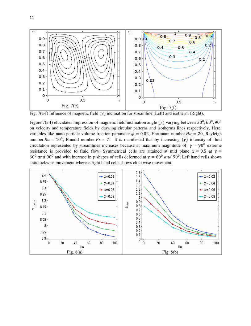
Fig. 7(e)
Fig. 7(f)
Fig. 7(a-f) Influence of magnetic field (𝛾) inclination for streamline (Left) and isotherm (Right).
Figure 7(a-f) elucidates impression of magnetic field inclination angle (𝛾) varying between 300, 600, 900
on velocity and temperature fields by drawing circular patterns and isotherms lines respectively. Here,
variables like nano particle volume fraction parameter 𝜙 = 0.02, Hartmann number 𝐻𝑎 = 20, Rayleigh
number 𝑅𝑎 = 106, Prandtl number 𝑃𝑟 = 7. It is manifested that by increasing (𝛾) intensity of fluid
circulation represented by streamlines increases because at maximum magnitude of 𝛾 = 900 extreme
resistance is provided to fluid flow. Symmetrical cells are attained at mid plane 𝑥 = 0.5 at 𝛾 =600 𝑎𝑛𝑑 900 and with increase in 𝛾 shapes of cells deformed at 𝛾 = 600 𝑎𝑛𝑑 900. Left hand cells shows
anticlockwise movement whereas right hand cells shows clockwise movement.
Fig. 8(a)
Fig. 8(b)

12
Fig. 8(c)
Fig. 8(d)
Fig. 8(a-d) Variation in entropy generation versus 𝜙. In figure 8(a-d) we analyzed the influence of nano particle volume fraction on thermal, viscous, magnetic
and total entropy generations along with variation in Hartmann number (Ha). Here, other parameter like 𝑅𝑎 = 1000, 𝛾 = 300, 𝑃𝑟 = 7 are fixed to attain optimized change. In fig. 8(a) we observed that magnitude
of thermal entropy generation has constant magnitude for 𝐻𝑎 = 0 and by increasing values of Ha from (0.1 ≤ 𝐻𝑎 ≤ 100) and by increasing 𝜙 from (0.02 ≤ 𝜙 ≤ 0.08) coefficient of entropy change due to
temperature gradient decrement. This can be explained by checking deprecating behavior of temperature
gradient against increase in 𝜙. Behavior of entropy generation due to viscous forces against increasing
values of nano particle volume fraction (𝜙) and Hartmann number (Ha) is delineated in fig. 8(b). It is
depicted that as we uplift value of (Ha) and (𝜙) decrement (𝑆𝑉𝑖𝑠𝑐) curves is manipulated. It is due to the
fact as we increase the value of (Ha) viscous forces became dominant and reduction movement of fluid
particles enriches as a consequence random generated due to viscous forces decays. It can also be seen that
for 𝐻𝑎 > 0 the magnitude of (𝑆𝑉𝑖𝑠𝑐) approaches to zero. Prediction about behavior of entropy generation
process to magnetic strength variation in flow field is divulged in fig. 8(c). It is depicted that at 𝐻𝑎 =0, 𝑆𝑚𝑎𝑔𝑛 = 0 and at certain stage of magnitude of Ha i.e. 40. It reduces to maximum values after attaining
maximum amplitude of curves at Ha=40. The magnitude of randomness generated due to magnetic field by
influenced by nano particle volume fraction. Impact of nano particle (𝜙) volume fraction and Hartmann
number (Ha) depreciates. Impact of nano particle volume fraction (𝜙) and Hartmann number (Ha) on
accumulative entropy generation coefficient 𝑆𝑇𝑜𝑡𝑎𝑙 is discussed in fig. 8(d). It is observed that by increasing (𝜙) and (Ha) in range of (0.02 ≤ 𝜙 ≤ 0.08) and (0 ≤ 𝐻𝑎 ≤ 100) total entropy coefficient depresses.

13
Fig. 9(a)
Fig. 9(b)
Fig. 9(a-b) Variation in entropy generation versus (𝑅𝑎). Variation in thermal, viscous and magnetic entropy generation against Rayleigh number (Ra) and Hartmann
number (Ha) is measured in figure 9(a-b). Hartmann number (Ha) is considered from 0 to 100 and taken
along x-axis whereas Rayleigh number is considered from 103𝑡𝑜 106. Figure 9(a) shows that at constant
and maximum magnitude of thermal entropy generation (𝑆𝑇ℎ𝑒𝑟𝑚) is attained at (Ha = 0) for different
magnitudes of Rayleigh number (Ra). It is important to note that when boost to high Hartmann number
(Ha) and Rayleigh number (Ra) is provide coefficient of thermal entropy generation reaches asymptotically
to zero. The reason behind decrementing behavior of (𝑆𝑇ℎ𝑒𝑟𝑚) is due to the fact that by increasing Hartmann
number (Ha) Lorentz forces are generated which reduces the velocity and temperature gradients in flow
field. This reduction in thermal differences reduces thermal irreversibility and at certain stage of (Ha)
development of thermal entropy becomes irrelevant. Change in viscous entropy generation coefficient (𝑆𝑣𝑖𝑠𝑐) versus mounting magnitude of Hartmann number (Ha) and Rayleigh number (Ra) is divulged in fig.
9(b). It is convenient to observe that by fixing nanoparticle volume fraction (𝜑) the viscous entropy
generation decrease against (Ha) whereas uplift is depicted against increasing magnitude of (Ra). This
decline in (𝑆𝑣𝑖𝑠𝑐) is due to decrease in natural convection which is produced due to latent impact of Lorentz
force. On other hand, increasing response to (𝑆𝑣𝑖𝑠𝑐) against (Ra) is due to reason that by increasing (Ra)
thermal buoyancy forces are produced which as an outcome generates temperature differences along with
randomness of particles in flow domain. In addition it is worthwhile to note that for (0 ≤ 𝐻𝑎 ≤ 100) and
fixing Ra = 1000 the magnitude of (𝑆𝑣𝑖𝑠𝑐) remains zero. This shows that by considering low magnitude of
(Ra) coefficient of viscous entropy becomes null.

14
Fig. 10(a)
Fig. 10(b)
Fig. 10(c)
Fig. 10(a-c) Entropy variation against (𝞬)
Fig. 10(a-c) investigates about influence of magnetic field inclination angle (𝞬) and Hartmann
number (Ha) on thermal, viscous and magnetic irreversibility’s is revealed. To see response of irreversibility coefficients in significant way Rayleigh number (Ra) and Prandtl number (Pr) are
fixed to 106 and 7 respectively. Here, in these sketches 𝞬=0 represent angles of inclination when
magnetic field is applied in direction of x-axis whereas 𝞬=900 shows that it is applied in vertical
direction. The considered range for Hartmann number in current figures is between 0 and 100,
while inclination angle of magnetic field is ranging from 00 𝑡𝑜 900. The magnitude of
nanoparticle volume fraction is each case is fixed at 4 %. Fig. 10(a) discloses the change in thermal
entropy production with respect to Hartmann number (Ha) and magnetic inclination angle (𝞬). It
is seen from this figure that when (Ha=0) coefficient of thermal entropy reaches to optimum
magnitude valued at 8.4 on vertical axis. It is also found that as we increase Hartman number

15
between 0 and 100 the magnitude of (𝑆𝑇ℎ𝑒𝑟𝑚) depresses whereas reverse behavior is depicted in
case of incrementing magnitude of magnetic field inclination angle (𝞬). This can be explained by
the augmentation of the thermal gradients via enhancement of convection currents in enclosure
with rise in magnetic field inclination angle. Fig. 10(b) represents deviation in curves measuring
change in viscous entropy coefficient against magnetic field inclination angle (𝛾) and Hartmann
number (Ha). From view of graph it is explicitly seen that by increasing (Ha), (𝑆𝑉𝑖𝑠𝑐) profile down
surges but opposite to it uplift is observed in case of magnetic field inclination angle (𝛾). It is due
to the argument that by increasing (𝛾) temperature difference is enhanced at different portions of
enclosure and thermal buoyancy forces are generated which as a conclusion execute convective
current. These currents produces enhancement in viscous entropy randomness. With regards to
magnetic irreversibility, it has been observed from fig. 10(c) that effect of magnetic field
inclination angle on magnetic entropy generation reverses from low Hartmann number (0≤ 𝐻𝑎 ≤40) to high Hartmann number (40< 𝐻𝑎 ≤ 100). Indeed, this figure discloses a decrease in
magnetic entropy measures for weaker Hartmann number and increasing function in case of
stronger magnitude of (Ha). It is clear that for constant Hartmann number the effect of inclination
angle on magnetic entropy is manifested through Lorentz force proved mathematically from
relation provided in eqs. (2.3) and through entropy generation (Eq. 14). Therefore, at low
Hartmann number, by increasing inclination angle, magnetic irreversibility dominates by extrinsic
character of Lorentz force which is expressed by a decrease in flow velocity. Whereas, at high
Hartmann number, the magnetic irreversibility dominates by the key impacts of the effective
electric conductivity, which increases by increasing the inclination angles.
Fig. 11 Influence on average Nusselt number for various 𝐻𝑎. Variation in heat flux coefficient against increasing magnitude of magnetic field inclination angle (𝞬)
and Hartmann number (Ha) is divulged in figure 11. Here, it is observed that for different

16
magnitude of (Ha) and by varying (𝞬) between 00 𝑡𝑜 300 and for 𝞬 > 600 average Nusselt number
increases.
4. Conclusion:
In current communication we have addressed the phenomenon of entropy production in natural
convective heat transfer of Cu-𝐻2𝑂 nanofluid enclosed in square enclosure. Magnetic field is
applied at different angles of inclination to measure its impact on irreversibility process.
Temperature gradient is provided in flow domain by providing constant heat at upper wall of
enclosure while rest of all boundaries are kept cold. Mathematical formulation of under
consideration problem is conceded in the form of coupled partial differential system. Solution of
governing equations are attained by implementing finite element scheme. Deviation in velocity
and temperature fields are discussed by sketching stream and isothermal patterns against involved
parameters. Three different types of entropy variations namely; magnetic, viscous and thermal
entropies are measured. So, the prime concern of our current effort is to disclose variation in
entropy generation in enclosure and prediction about factors effecting entropy measurements.
The key outcomes are itemized below
i) Symmetrical stream line contour at mid plane i.e. x = 0.5 is attained for Ha = 0 and by
fixing 𝜑 = 0.02 and 𝞬 = 30𝑜.
ii) Heat is propagated in the form of parabolic curves and initiated from upper surface of
enclosure due to provision of temperature gradient.
iii) Decrementing aptitude of (𝑆𝑇ℎ𝑒𝑟𝑚) is found against increasing value of nanoparticle
volume fraction (𝜑) for Ha > 0, whereas, for Ha = 0 a constant magnitude of (𝑆𝑇ℎ𝑒𝑟𝑚)
is depicted against each value of (𝜑) from 0.02 to 0.08.
iv) It is seen that curves representing variations in (𝑆𝑉𝑖𝑠𝑐) approaches towards zero with
change in (𝜑). v) It is adhered that magnetic entropy variation become zero at Ha = 0 while it increases
for Ha < 40 and after this critical range it start depreciating.
6. References:
[1] E. Mendoza, “Reflections on the Motive Power of Fire and other Papers on the Second Law of
Thermodynamics,” Dover Publications: New York, NY, USA, 1988.
[2] R. Clausius, “Mechanical Theory of Heat; Institute of Human Thermodynamics,” Publishing
Ltd. Chicago, IL, USA, pp. 1850–1865. 2006.
[3] A. Bejan, “Second law analysis in heat transfer,” Energy, pp. 720–732, 1980.
[4] G. H. R. Kefayati, N. A. Che Sidik,” Simulation of natural convection and entropy generation
of nonNewtonian nanofluid in an inclined cavity using Buongiorno’s mathematical model (Part II,
entropy generation),” Powder Technology, vol. 305, pp. 679-703, 2017.

17
[5] S. Parvin, A. J. Chamkha,” An analysis on free convection flow, heat transfer and entropy
generation in an odd-shapped cavity filled with nanofluid,” International communications in Heat
and Mass Transfer, vol. 54, pp. 8-17, 2014.
[6] I. Mejri, A. Mahmoudi, M. A. Abbasi, A. Omri, “Magnetic field effect on entropy generation
in a nanofluidfilled enclosure with sinusoidal heating on both side walls,” Powder Technology,
vol. 266, pp. 340-353m 2014.
[7] A. Mahmoudi, I. Mejri, M. A. Abbasi, A. Omri,” Analysis of the entropy generation in
nanofluid-filled cavity in the presence of magnetic field and uniform heat generation/absorption,”
Journal of Molecular Liquids, vol. 198, pp. 63-77, 2014.
[8] T. Armaghani, A. Kasaeipoor, N. Alavi, M. M. Rashidi,” Numerical investigation of water-
alumina nanofluid natural convection heat transfer and entropy generation in a baffled L-shaped
cavity,” Journal of Molecular Liquids, vol. 223, pp. 243-251, 2016.
[9] A. M. J. Al-Zamily, “Analysis of natural convection and entropy generation in a cavity filled
with multi-layers of porous medium and nanofluid with a heat generation,” International Journal
of Heat and Mass Transfer, vol. 106, pp. 1218-1231, 2017.
[10] A. E. M. Bouchoucha, R. Bessaïh, H. F. Oztop, K. Al-Salem, F. Bayrak, “Natural convection
and entropy generation in a nanofluid filled cavity with thick bottom wall: effect of non-isothermal
heating,” International Journal of Mechanical Science, vol. 126, pp. 95-105, 2017.
[11] H. R. Ashorynejad, B. Hoseinpour, “Investigation of different nanofluids effect on entropy
generation on natural convection in porous cavity,” European Journal of Mechanics B/Fluids, vol.
62, pp. 86-93, 2017.
[12] M. A. Sheremet, T. Grosan, I. Pop, “Natural convection and entropy generation in a square
cavity with variable temperature side walls filled with a nanofluid: Buongiorno’s mathematical
model,” Entropy, vol. 19, pp. 337, 1-16, 2017.
[13] A. I. Alsabery, M. S. Ishak, A. J. Chamkha, I. Hashim,” Entropy Generation analysis and
natural convection in a nanofluid-filled square cavity with a concentric solid insert and different
temperature distributions,” Entropy, vol 336, pp. 1-24, 2018.

18
[14] M. Siavashi, R. Yousofvand, S. Rezanejad, “Nanofluid and porous fins effect on natural
convection and entropy generation of flow inside a cavity,” Advanced Powder Technology, vol.
29, pp. 142-156, 2018.
[16] D. Kashyap, A. K. Dass, “Two-phase lattice Boltzmann simulation of natural convection in a
Cu-water nanofluid filled porous cavity: effects of thermal boundary conditions on heat transfer
and entropy generation,” Advanced Powder Technology, vol. 29, pp. 2707-2724, 2018.
[17] N. S. Gibanov, M. A. Sheremet, H. F. Oztop, N. Abu-Hamdeh, “Mixed convection with
entropy generation of nanofluid in a lid-driven cavity under the effects of a heat-conducting solid
wall and vertical temperature gradient,” European Journal of Mechanics / B Fluids, vol. 70, pp.
148-159, 2018.
[18] M. A. Mansour, S. Siddiqa, R. S. R. Gorla, A. M. Rashad, “Effect of heat source and sink on
entropy generation and MHD natural convection of Al2O3-Cu/water hybrid nanofluid filled with
square porous cavity,” Thermal Science and Engineering Progress, vol. 6, pp. 57-71, 2018.
[19] A. Rahimi, M. Sepehr, M. J. Lariche, A. Kasaeipoor E. H. Malekshah, “Entropy generation
analysis and heatline visualization of free convection in nanofluid (KKL model-based) –filled
cavity including internal active fins using lattice Boltzmann method,” Computers and Mathematics
with Applications, vol. 75, pp. 1814-1830, 2018.
[20] M. M. Rashidi, M. Nasiri, M. S. Shadloo, Z. Yang, “Entropy Generation in a Circular Tube
Heat Exchanger Using Nanofluids: Effects of Different Modeling Approaches,” Heat Transfer
Engineering, vol. 38, pp. 853-866, 2016.
[21] H. Yarmand, G. Ahmadi, S. Gharehkhani, S. Kazi, M. Safaei, M. Alehashem, A. Mahat,
“Entropy Generation during Turbulent Flow of Zirconia-water and Other Nanofluids in a Square
Cross Section Tube with a Constant Heat Flux,” Entropy, vol. 16, pp. 6116-6132, 2014.
[22] F. A. Soomro, K. Z. H. Rizwan-ul-Haq, Q. Zhang, “Numerical study of entropy generation in
MHD water-based carbon nanotubes along an inclined permeable surface,” Eur. Phys. J. Plus, vol.
132, 2017
[23} B. Darbari, S. Rashidi, J. A. Esfahani, “Sensitivity analysis of entropy generation in nanofluid
flow inside a channel by response surface methodology,” Entropy, vol. 18, no. 52, 2016.

19
[24] M. M. Bhatti, T. Abbas, M. Mehdi, M. Rashidi, S. Mohamed, E. Ali, “Numerical simulation
of Entropy Generation with thermal radiation on MHD Carreau Nanofluid towards a Shrinking
Sheet,” Entropy, vol. 18, no. 200, 2016.
[25] Y. A. J. Mohammad, R. S. Mohammad, A. Abdullah, K. N. Truong, P. B. F. Enio, “Entropy
Generation in Thermal Radiative Loading of Structures with Distinct Heaters,” Entropy, vol. 19,
no. 506, 2017.
[26] M. R. Mohammad, N. Mohammad, S. S. Mustafa, Y. Zhighang, “Entropy Generation in a
Circular Tube Heat Exchanger Using Nanofluids: Effects of Different Modeling Approaches,” J.
Heat Transf. Eng., 2017.
[27] S. K. Das, S. U. Choi, T. Pradeep, “Nanofluids: science and technology,” Hoboken,
NJ: Wiley, p.397, 2007.
[28] K. F. V. Wong, O. D. Leon, “Applications of nanofluids: current and future,” Adv Mech
Eng. Vol. 2, pp. 1–11, 2010.
[29] S. Chol, “Enhancing thermal conductivity of fluids with nanoparticles” ASME-Publications-
Fed, vol. 231, pp. 99-106, 1995.
[30] J. A. Eastman, et al., “Anomalously increased effective thermal conductivities of ethylene
glycolbased nanofluids containing copper nanoparticles,” Applied physics letters, vol. 78, pp. 718-
720, 2001.
[31] M. A. Mansour, et al., “Numerical simulation of mixed convection flows in a square lid-
driven cavity partially heated from below using nanofluid,” International Communications in Heat
and Mass Transfer, vol. 37, pp. 1504-1512, 2010.
[32] M. Sheikholeslami, “Influence of magnetic field on nanofluid free convection in an open
porous cavity by means of Lattice Boltzmann method,” J. Mol. Liq. Vol. 234. Pp. 364–374, 2017.
[33] M. Sheikholeslami, “Numerical simulation of magnetic nanofluid natural convection in
porous media” Phys. Lett. A. vol. 381, pp. 494–503, 2017.

20
[34] D. Yadav, D. Lee, H. H. Cho, “The onset of double-diffusive nanofluid convection in a
rotating porous medium layer with thermal conductivity and viscosity variation: a revised model,”
J. Porous Media, vol. 19, pp. 31–46, 2016.
[35] Z. H. Khan, W. A. Khan, M. Hamid, H. Liu, “Finite element analysis of hybrid nanofluid
flow and heat transfer in a split lid-driven square cavity with Y-shaped obstacle,” Physics of
Fluids, vol. 32, Issue 9.
[37] M. A. Shermet, T. Grosan, I. Pop, “Free convection in a square cavity filled with a porous
medium saturated by nano uid using Tiwari and Das nano uid model”, Trans. Porous Media, vol.
106, pp. 595-610, 2015.
[37] F. Mabood, S. Shateyi, M. M. Rashidi, E. Momoniat, N. Freidoonimehr, “MHD stagnation
point ow heat and mass transfer of nano uids in porous medium with radiation, viscous dissipation
and chemical reaction,” Adv. Powder Technol., vol. 27, pp. 742-749.
[38] M. Ghalambaz, F. Moattar, M. A. Shermet, I. Pop, “Triple-diffusive natural convection in a
square porous cavity,” Trans. Porous Media, vol. 111, pp. 59-79, 2016.
[39] A. Mahmoud, I. Mejri, M. A. Abbasi, A. Omri, “Analysis of MHD natural convection in a
nano liquid-filled in open cavity with non-uniform boundary condition in the presence of uniform
heat generation/absorption,” Powder Technol., vol. 269, pp. 275-289.
[40] M. Ziaei-Rad, M. Saeedan, E. Afshari, “Simulation and prediction of MHD dissipative nano
uid ow on a permeable stretching surface using articial neural network,” Appl. Thermal Eng., vol.
99, pp. 373-382, 2016.
[41] M. Ziaei-Rad, A. Kasaeipoor, M. M. Rashidi, G. Lorenzini, “A similarity solution for
mixedconvection boundary layer nano fluid ow permeable surface,” J. Thermal Sci. Eng. Appl.,
vol. 9.
[42] D. Poulikakos, A. Bejan, B. Selimos, K. Blake, “High rayleigh number convection in a fluid
overlaying a porous bed,” Int. J. Heat Fluid Flow, vol. 7, pp. 109–116, 1986.

21
[43] C. Beckermann, R. Viskanta, S. Ramadhyani, “Natural convection in vertical enclosures
containing simultaneously fluid and porous layers,” J. Fluid Mech. Vol. 186, pp. 257–284, 1988.
[44] C. L. Chen, C. H. Cheng, “Buoyancy-induced flow and convective heat transfer in an inclined
arc-shape enclosure,” Int. J. Heat Fluid Flow, vol. 23, pp. 823-830, 2002.
[45] M. November, M. Nansteel, “Natural convection in rectangular enclosures heated from below
and cooled along one sideInt,” J. Heat Mass Transf., vol. 30, pp. 2433-2440, 1987.
[46] M. M. Ganzarolli, L. F. Milanez, “Natural convection in rectangular enclosures heated from
below and symmetrically cooled from the sides,” Int. J. Heat Mass Transf., vol. 38, pp. 1063-1073,
1995.
[47] F. Moukalled, S. Acharya, “Natural convection in a trapezoidal enclosure with offset baffles,”
J. Thermophys. Heat Transf., vol. 15, pp. 212-218, 2001.
[48] R. Chinnakotla, D. Angirasa, R. Mahajan, “Parametric study of buoyancy-induced flow and
heat transfer from L-shaped corners with asymmetrically heated surfaces”, Int. J. Heat Mass
Transf., vol. 39, pp. 851-865, 1996.
[49] A. C. Baytas, “Entropy generation for natural convection in an inclined porous cavity,” Int.
J. Heat Mass Transfer, vol. 43, pp. 2089–2099, 2000.
[50] K. L. Walker, G. M. Homsy, “Convection in a porous cavity,” J. Fluid Mech. Vol. 87, pp.
449–474.
[51] A. Bejan, “On the boundary layer regime in a vertical enclosure filled with a porous medium,”
Lett. Heat Mass Transfer, pp. 693–102, 2011.
[52] Y. Varol, H. F. Oztop, T. Yilmaz, “Two-dimensional natural convection in a porous triangular
enclosure with a square body,” Int. Commun.Heat Mass Transfer, vol. 34, pp. 238-247, 2007.
[53] H. F. Oztop, I. Dagtekin, M. Duranay, “Analysis of natural convection problem in a cavity
with partially heated and block inserted,” Proceedings of 13rd Heat Science and Technology
Congress, Turkey, pp. 217-222, 2001.

Figures
Figure 1
Physical structuring of problem.
Figure 2
Sequence of grids on space mesh level: 1, 2, 3 (from left to right)

Figure 3
P2 - P1 �nite element pair with placement of degrees of freedom.
Figure 4

Discretization of computational domain
Figure 5
Step involved in implemented method.
Figure 6
(a-h) In�uence of Hartmann number (Ha) on streamline (Left) and isotherm (Right)

Figure 7
(a-f) In�uence of magnetic �eld (γ) inclination for streamline (Left) and isotherm (Right).

Figure 8
(a-d) Variation in entropy generation versus .

Figure 9
(a-b) Variation in entropy generation versus (Ra).

Figure 10
(a-c) Entropy variation against ()

Figure 11
In�uence on average Nusselt number for various Ha.