five-year review report: first five-year review report … · five-year review reportsdms docid...
TRANSCRIPT

Five-Year Review Report SDMS DocID 237029
First Five-Year Review Reportfor the
Somersworth Sanitary Landfill Superfund SiteSomersworth, New Hampshire
September 2005
PREPARED BY:United States Environmental Protection Agency
Region IBoston, Massachusetts
Approved by: Date:
Susan StudlienSuperfund Division DirectorU.S. ERA, Region I

[This page intent ional ly left b lank.

TABLE OF CONTENTS
List of AbbreviationsExecutive SummaryFive-Year Review Summary Form
Page1 INTRODUCTION .......................................................................................................I
2. SITE CHRONOLOGY.
3. BACKGROUND............
3.1 Physical Characteristics...................................................................................^
3.2 Land and Resource Use ....................................................................................4
3.3 History of Contamination .................................................................................5
3.4 Basis for Taking Action....................................................................................6
4. REMEDIAL ACTIONS.............................................................................................^
4.1 Remedy Selection ............................................................................................. 8
4.2 Remedy Implementation................................................................................. 11
4.2.1 Source Control Preferred Remedial Action (PRA)..................................... 11
4.2.2 Management of Migration Preferred Remedial Action (PRA)................... 11
4.2.3 Institutional Controls................................................................................... 124.2.4 Groundwater Monitoring............................................................................. 13
4.3 Landfill Gas (LFG) Venting Trench............................................................... 14
4.4 System Operations/Operations and Maintenance (O&M).............................. 15
5. PROGRESS SINCE THE LAST FIVE-YEAR REVIEW................................... 16
6. FIVE YEAR REVIEW PROCESS.......................................................................... 17
6.1 Administrative Components........................................................................... 17
6.2 Community Involvement................................................................................ 17
6.3 Document Review .......................................................................................... 17
6.4 Data Review.................................................................................................... 17

6.5 Site Inspection................................................................................................. 20
6.6 Interviews........................................................................................................ 20
7. TECHNICAL ASSESSMENT.................................................................................21
7.1 Is the remedy functioning as intended by the decision documents? ............... 21
7.2 Are the exposure assumptions, toxicity data, cleanup levels, and remedialaction objectives used at the time of the remedy selection s t i l l valid?....................... 21
7.3 Has any other informat ion come to light that could call into question toprotectiveness of the remedy?..................................................................................... 22
8. ISSUES 23
9. RECOMMENDATIONS AND FOLLOW-UP ACTIONS.................................. 24
II). PROTECTIVENESS STATEMENT......................................................................25
11. NEXT REVIEW ........................................................................................................26
Table 1:Table 2:Table 3:
LIST OF TABLES
Chronology of Site EventsIssuesRecommendations and Follow-Up Actions
Attachment A:Attachment B:
Attachment C:
LIST OF ATTACHMENTS
List of Documents ReviewedFigure 1 - Site Location and Figure 2 - Site Plan and Table 2.3from 2004 Annual ReportCity of Somersworth Groundwater Protection District ZoningOrdinance
111

LIST OF ABBREVIATIONS
BRW Bedrock WellCD Consent DecreeCE chlorinated etheneCTW Chemical Treatment WallDCE dichloroetheneERA United States Environmental Protection Agencyft feetGMZ Groundwater Management ZoneICL Interim Cleanup Levelsin inchLFG Landfill GasL-GVS Landfill Gas Venting SystemNHDES New Hampshire Department of Environmental ServicesNPL National Priorities ListO&M Operation and MaintenancePCE tctrachloroethcneP1D photoionization detectorPLC permeable l and f i l l coverPOC point of complianceppb parts per b i l l i onppm parts per mi l l ionPRA Preferred Remedial ActionPRB permeable reactive barrierRA Remedial ActionRD Remedial DesignRI/FS Remedial Investigation/Feasibility StudyROD Record of DecisionSAP Sampling and Analysis PlanSOW Statement of WorkTCE trichloroethene/xg/L micrograms per l i terVC vinyl chlorideVOC volatile organic compoundWSD Work Settling DefendantsZVI zero-valent iron
I V

[This page in t en t i ona l l y left blank.]

Executive Summary
The remedy implemented at the Somcrsworth Sanitary Landfil l Superfund Site inSomersworth, New Hampshire included installation of a Chemical Treatment Wall(CTW) along the downgradient edge of the l a n d f i l l , placement of a permeable soil coverover the landfill , installation of a bedrock extraction well and recharge of extractedground-water into a gallery on the l andf i l l , i n s t i t u t iona l controls, and monitored naturalattenuation of contaminated groundwater down gradient of the CTW. The Site achievedconstruction completion on September 9, 2005. The trigger for this First Five-YearReview Report was the actual start of construction on July 17, 2000.
The remedy is considered protective in the short-term; however in order for theremedy to be protective in the long-term, fol low-up actions need to be taken. Long-termpiotectiveness wi l l be achieved once additional not i f icat ion of property owners wi th inthe Groundwater Management Zone (GMZ) is provided in accordance with currentState requirements, newly installed shallow and bedrock monitoring wells are sampledto confirm a "clean-edge" along the northern boundary of the GMZ, and the recentaromalies identified at the CTW near the CTW-20 transect are more fu l l y understoodthrough the monitoring of new wells ins ta l led by the Work Sett l ing Defendants (WSD)in August 2005.

[This page intentionally left b lank.
vn

Five-Year Review Summary Form
SITE IDENTIFICATION
Site name (from WasteLAN): Somersworth Sanitary Landfill
ERA ID (from WasteLAN): NHD980520225
Region: State: NH City/County: Somersworth/Strafford
NPL status: [X] Final D Deleted D Other (specify)
Remediation status (choose all that apply): D Under Construction ^ Operating £<] Complete
Multiple Oils?' D YES NO Construction completion date: 09/09/2005
Has site been put into reuse? YES D NO
Lead agency: [x] EPA n State D Tribe ID Other Federal Agency ______________
Author name: Michael Jasinski
Author title: Superfund Section Chief Author affiliation: EPA Region I
Review period:- 12/20/2004 to 09/23/2005
Date(s) of site inspection: 06/15/2004 and throughout 2005
Type of review:IS Post-SARA O Pre-SARAD Non-NPL Remedial Action SiteD Regional Discretion
73 NPL-Removal onlyn NPL State/Tribe-lead
Review number: 1 (first) D 2 (second) D 3 (third) LJ Other (specify) _
Triggering action:D Actual RA Onsite Construction at OUC] Construction Completion
n Other (specify)
Actual RA Start at OU# _ 1_D Previous Five-Year Review Report
Triggering action date (from WasteLAN): 07/17/2000
Due date (five years after triggering action date): 07/17/2005* ["OITrefers to operable unit.]** [Review period should correspond to the actual start and end dates of the Five-Year Review in
WasteLAN.1
Vlll

Five-Year Review Summary Form, cont'd.
Issues:
Resolve all comments identified through EPA and NHDES review o] the "Annual Monitoring andDemonstration of Compliance Report for 2004. "
Recommendations and Follow-up Actions:
(a) Provide additional notification of Property Owners within the GMZ:
(b) Install and sample additional monitoring wells within the GMZ.;
(c) Conduct additional evaluations of MNA within the gronndwater dow'n gradient of the CTW; and
(el) Perform additional monitoring of groundwater wells installed by the WSD in August 2005 near the CTW-20 transect.
Protectiveness Statement(s):
The remedv is considered protective in the short-term; however in order for the remedy to beprotective in the long-term, follow-up actions need to be taken. Long-term protectiveness will beachieved once additional notification of property owners within the Gronndwater ManagementZone (GMZ) is provided in accordance with current State requirements, newl\ installed shallowand bedrock monitoring wells are sampled to confirm a "clean-edge" along the northernboundary of the GMZ, and the recent anomalies identified at the CTW near the CTW-20 transectare more fiillv understood through the monitoring of new wells installed by the WSD in August2005.

1. INTRODUCTION
The purpose of a five-year review is to determine whether the remedy at a site isprotective of human health and the environment. The methods, findings, andconclusions of reviews are documented in Five-Year Review reports. In addition, Five-Year Review reports identify issues found during the review, if any,and i d e n t i f yrecommendations to address them.
The Agency is preparing this Five-Year Review report pursuant the ComprehensiveEnvironmental Response, Compensation, and Liabili ty Act (CERCLA) §121 and theNational Oil and Hazardous Substances Pollution Contingency Plan (NCP). CERCLASection 121 states:
// the President selects a remedial action that results in any hazardoussubstances, pollutants, or contaminants remaining at the site, the President shallreview such remedial action no less often than each five years after the initiation ofsuch remedial action to assure that human health and the environment are beingprotected bv the remedial action being implemented. In addition, if upon suchreview it is the judgement of the President thai action is appropriate at such site inaccordance with section 11041 or f 106], the President shall take or require suchaction. The President shall report to the Congress a list of facilities for which suchreview is required, the results of all such reviews, and anv actions lakes as a resultof such reviews..
The Agency interpreted this requirement further in the NCP; 40 CFR§300.430(f)(4)(ii) states:
// a remedial action is selected that results in hazardous substances,pollutants, or contaminants remaining at the site above levels that allow forunlimited use and unrestricted exposure, the lead agencv shall review such actionno less often than every five years after initiation of the selected remedial action.
The United States Environmental Protection Agency (EPA), Region I, hasconducted this five-year review of the selected remedy at the Somersworth SanitaryLandfi l l Superfund Site (the "Site") in Somersworth, New Hampshire. The review wasconducted by the Section Chief for the New Hampshire/Rhode Island Superfund Sectionat Region I, with the assistance of the Working Sett l ing Defendants and the State of
1

New Hampshire, from December 2004. through September 2005. This reportdocuments the results of the review.
This is the first five-year review for the Site. The triggering action for this statutoryreview is the date of actual on-site mobili/ation for construction of the first phase of theremedy which was July 17, 2000. The five-year review is required due to the fact thathu/ardous substances, pollutants , or contaminants remain at the Site above levels thatallow for unlimited use and unrestricted exposure.

2. SITE CHRONOLOGY
The chronology of events for the Site is presented in Table 1 below:
Table 1: Chronology of Site Events
Major Activity
Bedrock ExtractionWell Instal lat ionRemedial Action
Design
Construction ofChemical Treatment
Wall (CTW)
Construction ofLandf i l l Cover andBedrock Extraction
SystemConstruction of
Landf i l l Gas (LFG)Venting System
rYe-Final Inspection
Date
1981
Sept- 1983
June- 1994
April- 1996April- 1999July-2000
8-Jul-20()()l-Aug-2000ll-Sep-200028-Sep-2000
6-Jun-20()l
29-Aug-2()013()-Oct-2()03
l-Nov-2003
12-Dec-2003
18-Dec-2()()3
8-Jan-20()4
ll-Jun-200415-Jun-2()()4
Milestone
City ceased waste disposal at Site
Site placed on National Priority List
Record of Decision (ROD) Signed
Insta l la t ion of BRW-1100% Design Approved by EPA and NHDESUpdated 100% Design CompletedIn i t i a t i on of CTW Workpad ConstructionExcavation of First CTW PanelBackf i l l i ng of Final CTW PanelC'ompletion of CTW Construction Activit iesProject Kick-Off Meeting and Initiation ofConstructionFinal Inspection Meeting for Cover andBedrock ExtractionPre -Construction Meeting on SiteIn i t i a t i on of Excavation Activi t ies for LFGVenting TrenchC'ompletion of Excavation for LFG VentingTrenchC'ompletion of Backf i l l ing of LFG VentingTrenchC'ompletion of Site Cirading for LFG VentingTrenchC'ompletion of Site Restoration for LFGVenting TrenchPre-Final Inspection Meeting

3 BACKGROUND
3.1 Physical Characteristics
The Somersworth Sanitary Landfill Superfund Site (the ("Site") is located on thenorth side of Blackwater Road approximately one mile southwest of the center of theCity of Somersworth (the "City") in Strafford County, New Hampshire as shown inFigure 1. The Site layout is shown in Figure 2. The dominant Site feature is a formersanitary l a n d f i l l that extends over an area of approximately 26 acres. The extent of theproperty currently owned by the City at and around the landfill is shown on Figure 1.
The landfi l l is located entirely wi thin the Peters Marsh Brook surface waterdrainage basin. The brook flows northwesterly through the wetlands at the Site intoTalc's Brook, which in turn flows into the Salmon Falls River which is located aboutone mile east of the Site (see Figure 1).
The Site is relatively flat and low lying (see Figure 2) except that the quarryingac t iv i t i e s immediately to the north of the landf i l l have resulted in the presence of a 15 to20-foot vertical escarpment which runs parallel to the northern edge of the waste. Thewestern edge of the waste slopes downward toward the wetland.
The Site is underlain by an unconfined sand and gravel aquifer ranging from about15 to 75 feet thick. Metamorphic bedrock occurs beneath the sand and graveloverburden deposits. A peat layer is present at ground surface in and near the wetland.G-oundwater flows through the overburden in a northwesterly direction. The bedrock isfractured, with flow in the shallow bedrock appearing to be s l igh t ly north of west.Groundwater from both the bedrock and overburden discharges to Peters Marsh Brookand the wetland.
3.2 Land and Resource Use
The l andf i l l accepted municipal and industrial wastes from the mid-1930's to 1981.In t i a l l y the wastes were burned, but in 1958, the burning was stopped and the wasteswere landf i l led after excavating the natural soils. Soils were used to cover the wastes

dai ly and the l a n d f i l l expanded westward. The approximate extent of the 26-acrelandf i l l is shown on Figure 2.
The City of Somcrsworth owns the entire landfill area and much of the wetlanda:~eas to the northwest of the former l and f i l l . Numerous residential properties exist tothe south, cast and west of the Site, including two apartment buildings located adjacentto the northeast corner of the Site. A National Guard Armory and fire station are alsolocated to the cast of the Site, and a cemetery is located to the northeast of the Site.
Approximately 10 acres of the eastern portion of the Site have been reclaimed bythe City on their own accord (i.e., without EPA or State review or approval) for use asrecreational faci l i t ies , tennis and basketball courts, ball f ields, and a playground.Additional reuse options for the remaining 15+ acres of the landfi l l area have includedthe potential for soccer fields while the remaining areas of the Site are principallywetlands.
3.3 History of Contamination
Groundwater sampling conducted at the Site during the Remedial Investigation andFeasibility Study (RI/FS) between 1985 and 1992 indicated the presence of thefollowing VOCs:
• trichloroethene (also know as trichloroethylene; TCE);• tetrachloroethene (also known as tetrachloroethylene or perchloroethylene;
PCE);• l , l -dichloroethene(l , l -DCE);• cis and trans isomers of 1,2-dichloroethene (cis-l,2-DCE and trans-l,2-DCE,
respectively);• 1,2-dichloroethanc (1,2-DCA);• v iny l chloride (VC);• ben/ene; and• mcthylene chloride (also known as dichloromethane).
Metals (specifically chromium and arsenic) were detected in groundwater samplesdiring the RI/FS but their concentrations were s imilar to background levels.

Polychlorinated biphenyls (PCBs) and pesticides were not detected in the groundwatersamples.
The 1994 ROD indicated that the groundwater VOC distribution had reached asieady-state condition and VOCs had extended approximately 1,700 feet down gradientof the waste.
Soils sampled during the RI/FS had low concentrations of VOCs and semi-volatileorganic compounds detected while inorganic compounds were found at or belowbackground levels. VOCs were detected in sediment and surface water samples fromthe wetlands in 1985 and 1986; however, no VOCs were detected during subsequentsampling of the surface water in 1992 (sediments were not re-sampled).
3.4 Basis for Taking Action
The ROD for the Site (Section IV) states that, "The selected remedy was developedby combining components of different source control and management of migrationalternatives to obtain a comprehensive approach for Site remediation. In summary, theremedy provides treatment of contaminated overburden and bedrock ground water withflashing of contamination from the source area. This remedial action w i l l address theprincipal threat to human health and the environment posed by the site: the potentialfuture ingestion of contaminated groundwater."O O
The ROD also established Interim Cleanup Levels (ICLs) for eight volatile organiccompounds (VOCs) in groundwater as listed below:
• benzene 5 micrograms per liter (/ug/1)• methylene chloride 5 /ug/1• tetrachloroethene (PCE) 5 ^ig/1• trichloroethene (TCE) 5 /ig/1• 1,1-dichIoroethene (1,1-DCE) 7 /ig/l• cis-l,2-dichloroethene (cDCE) 70 ptg/1• trans-l,2-dichloroelhcne (tDCE) 100 ptg/1• vinyl chloride (VC) 2 ^ig/1

The six chlorinated ethenes (i.e., PCE, TCE, 1,1-DCE, cDCE, tDCE, and VC) inthe above list are referred to as the "CEs" at the Site.

4. REMEDIAL ACTIONS
4.1 Remedy Selection
The Record of Decision (ROD) for the Somersworth Sanitary Landfill SuperfundSite (the "Site") was signed on June 21, 1994 (EPA, 1994).
The remedial action objectives stated in Section VII , Part A of the ROD were:
• Prevent ingestion of contaminated groundwater by local residents;
• Prevent the public from coming into direct contact with contaminated solidwastes, surface soils, surface water, and sediments;
" Reduce or eliminate migration of contaminants from the solid wastes orsoils into ground or surface water;
• Reduce or eliminate off-siic migration of contaminants in excess ofregulated allowable l imits ; and
• Ensure that the ground water and surface water have residual contaminantlevels that are protective of human health and the environment.
To meet these objectives, the selected remedy described in the 1994 ROD includedboth source control and management of migration components to obtain acomprehensive remedy for the Site.
The source control remedial components of the preferred alternative included:
• "installation of a treatment wa l l composed of impermeable barriersections and innovative, permeable, chemical treatment sectionsto provide in-s i tu ( in-place), flow-through treatment ofcontaminated ground water at the l and f i l l waste boundary (thecompliance boundary). The hairier sections, sheet pi l ing orslurry walls, w i l l direct contaminated ground water through the

treatment sections where detoxification of the VOCs w i l l occur;and
• placement of a permeable cover over the landfill allowingprecipitation to flush contamination from the waste area. Thiscover will remain as long as contaminants continue to leach fromthe landf i l l waste and the chemical treatment "wall" isfunctioning. After cleanup levels have been achieved and can bemaintained without use of the treatment "wall," EPA wi l levaluate an appropriate l andf i l l cover to be installed to close thelandfill."
The management of migration remedial components of the preferred andcontingency remedies included:
• "installation of a pump in bedrock monitoring well B-12R toextract contaminated ground water. The contaminated groundwater will be either discharged onto the landfill to enhanceflushing or injected just upgradient of the chemical treatment wallto receive treatment for the preferred alternative or treated withthe extracted overburden ground water for the contingencyalternative. The need for bedrock ground water extraction wellsdown gradient of the chemical treatment wall or perimeter slurrywall w i l l be investigated during the design. This investigationwill focus on the number, location, and flow rate of the wells; thetiming of their instal lat ion; and the impacts on the overall groundwater cleanup; and
• natural attenuation of contaminated groundwater beyond thecompliance boundary to lower contaminant concentrationsthrough physical, chemical and biological processes unt i lgroundwater cleanup levels are met."
Additional remedial components of the selected remedy included:

• "institutional controls to ensure that the affected ground waterw i l l not be used un t i l ground water cleanup levels have been met;and
• a detailed ground water monitoring program to be developedduring remedial design. The program wil l address long-termmonitoring of the aquifer and performance monitoring of thechemical treatment wall."
Final ly , the 1994ROD included a contingency alternative. The contingencyalternative was to be invoked if it was determined that the source control preferredalternative would not meet performance standards. The source control contingencyalternative included:
• "construction of a diversion trench on the upgradient side of the landfil lto intercept and divert groundwater around the l andf i l l . To the extentpracticable, this diverted groundwater w i l l be used to recharge the downgradientwetlands. A perimeter slurry wall would be completed around the landfillwaste. Permeable treatment sections of chemical treatment wall would beremoved and replaced by slurry wall material. The f inal component would be al a n d f i l l cover which complies with RCRA C requirements. The purpose ofthese components is to lower the ground water to below* the waste in an attemptto meet interim ground water cleanup levels in the overburden aquifer at thecompliance boundary. The ground water levels would be monitored todetermine if the water table would be lowered below the waste and groundwater qual i ty would be monitored to ensure that overburden ground water wil lmeet interim ground water cleanup levels at the compliance boundary. If eitherof these conditions cannot be met, then extraction and treatment of overburdenground water from within the slurry wall w i l l be implemented. The remedialdesign will determine the number, location and pumping rates of each well, aswell as, the most appropriate treatment technology and discharge location. On-site treatment and disposal methods and pretreatment and discharge at theSomersworth wastewater treatment faci l i ty are the two options which wi l l beevaluated."
10

4.2 Remedy Implementation
The components of the source control and management of migration preferredremedial action (PRA) that have been implemented at the Site are described in thefollowing subsections.
4.2.1 Source Control Preferred Remedial Action (PRA)
The Source Control PRA included installation of a zero-valent iron (ZVI) ChemicalTreatment Wall (CTW) to provide in-si tu, flow-through treatment of groundwatercontaining chlorinated ethenes (CEs) at the downgradicnt edge of the wastemanagement area of the landfi l l . Construction of the CTW commenced in July, 2000and was completed in September, 2000 at the location shown in Figure 2. According tothe Statement of Work in the Consent Decree (EPA, 1995), the CTW must prevent alluntreated overburden ground water that contains CEs at concentrations greater thanIrterim Cleanup Levels (ICLs) from migrating from the landfill to areas beyond thepoint of compliance (POC), except for insubstantial amounts of such groundwater. ThePOC is the edge of the waste management area, except where the CTW has beenconstructed, in wh ich case it is the outer edge of the CTW
The Source Control PRA also included placement of a permeable landfill cover(PLC) over the waste management area. The purpose of the PLC is to prevent directcontact with the underlying waste material, allow for infiltration of precipitation throughthe l and f i l l and control erosion. The PLC, which was installed in 2001, consists ofapproximately six inches of coarse backf i l l material and six inches of topsoil seededwith native grass. The PLC covers the portion of the l andf i l l not currently used forrecreational act ivi t ies.
Finally, the Source Control PRA must also assure that groundwater migrating fromthe l and f i l l to areas beyond the POC does not contain >ICL concentrations of benzeneor methylene chloride (EPA, 1995).
4.2.2 Management of Migration Preferred Remedial Action (PRA)
The Management of Migration PRA included ins ta l la t ion of a bedrock,groundwater extraction well (BRW-1), located adjacent to bedrock monitoring well B-12R, which is approximately 80 feet south of the edge of the waste (see Figure 2). The

attraction well was installed in April , 1996, while the infrastructure needed to extractaid discharge contaminated groundwater into an inf i l t ra t ion gallery located on top of thelandfi l l was completed during the summer of 2001. Bedrock groundwater extractioncommenced in November, 2001, with discharge of the extracted groundwater to theinfi l t rat ion gallery located upgradient of the CTW. As of January, 2005 a total of9,075,196 gallons of groundwater has been pumped from BRW-1 and dischargedthrough the infil tration gallery located on top of the landfi l l .
In addition to bedrock groundwater extraction at BRW-1 (and groundwatertreatment via the CTW), natural attenuation is also a component of the Management ofMigration PRA. Monitoring for natural attenuation parameters has occurred sincecompletion of the CTW and operation of the bedrock extraction commenced, asd;scussed further in Section 4.2.4 below.
4.2.3 Inst i tut ional Controls
The PRA also included ins t i tu t ional controls. The purpose of the inst i tut ionalcontrols is to ensure that the affected groundwater wi l l not be used for any purpose unt i lcleanup levels have been met; the hydrology of the Site is not adversely affected by thedrilling or use of any we l l s at or near the Site; there is no disturbance to the waste left inplace and the integrity of the cap is maintained. The PRA 100% Design andDemonstration of Compliance Plan (Beak and GeoSyntec, 1999) calls forimplementation of institutional controls at the Site through the installation of fencing,other physical barriers and access controls, and land and groundwater use restrictions.
Fencing and other physical barriers have been installed around active and accessiblecomponents of the PRA to discourage vandalism and tampering and provide protectionto these components, as listed below.
• The control box and the underground vault for the extraction system are protectedwith lockable covers or doors. The inf i l t rat ion gallery and extraction well have beenprotected by f lushmount locking protective covers.
• Protective steel casings have been installed over all monitoring wells and are lockedusing heavy gauge padlocks (i.e., to withstand unauthorized access using boltcutters).
12

• Shrubs have been planted around the soil gas vent pipes of the Landfill Gas ventingsystem (see description below in Section 4.2.5).
Pursuant to its zoning and land use authority, The City of Somersworth, a WorkingSettling Defendant (WSD) under the CD, has established a Groundwater ManagementZone ("GMZ") by legislative enactment. The boundaries of the GMZ are the sameboundaries as presented on the Groundwater Management Zone Overlay Map includedin the PRA 100% Design and Demonstration of Compliance Plan. The withdrawal ofgroundwater wi th in the GMZ for any purpose is prohibited. The City of Somersworthnotified its residents of the groundwater use restrictions by publishing legal notices inarea newspapers which described the restrictions and by posting these same notices atCity Hall. In addition, the Somersworth City Council and Planning Board held separateand distinct public hearings wi th separate and distinct notifications prior to the adoptionof the groundwater zoning restrictions. If the zoning ordinance is repealed or amendedso that it no longer prohibits the withdrawal of groundwater wi thin the GMZ, then othertypes of ins t i tu t ional controls w i l l be implemented in accordance with the SOW. Acopy of Chapter 19, Section 10 of the City of Somersworth Zoning Ordinance isappended to this Five-Year Review Report as Attachment C along with a copy of theGroundwater Management Zone Overlay Map.
Where access to land is required for monitoring, remedy construction or otherresponse actions, land easements or access agreements w i l l be used to the extentnecessary, as identified in the PRA 100% Design and Demonstration of CompliancePlan. An easement has been obtained for extraction well BRW-I. Exist ing agreementsobtained from various property owners to access existing monitoring wells for samplingand maintenance are being used throughout implementation of the PRA.
4.2.4 Groundwater Monitoring
The Groundwater Monitoring Plan for the Site is described in the Sampling andAnalysis Plan (GeoSyntec, 200la) that was prepared to satisfy the monitoringrequirements identified in the Statement of Work (SOW) appended to the ConsentDecree (CD). The groundwater monitoring network is shown in Figure 2.
The purpose of th i s monitoring plan is to document the progress of the groundwaterremediation in both the overburden and bedrock, and to determine when the
13

groundwater remediation has achieved the overall goals of the selected remedy.Groundwater remediation is required un t i l the ICLs are achieved at and beyond the POCat the Site. The WSDs must demonstrate that the ICLs have not been exceeded for aperiod of three consecutive years at every well at and beyond the POC using theevaluation procedure defined in 40 CFR 264.97.
The current monitoring program includes sampling selected wells three timesannual ly to evaluate whether the CTW and bedrock extraction well are meeting theICLs. In addition, certain wells are sampled annual ly to evaluate natural attenuationprocesses beyond the POC and to evaluate the background conditions at the Site. TheCTW is also hydraulically tested annually to evaluate any changes in flow conditions.
All groundwater monitoring results are reported to EPA and NHDES as part of theAnnual Monitoring and Demonstration of Compliance Reports.
4.3 Landfill Gas (LFG)Venting Trench
Based on soil gas monitoring conducted in 2001 and 2002, the EPA and NHDESbelieved that additional actions, such as a LFG venting trench, were necessary tomitigate methane releases near the perimeter of the landfi l l . While this additional actionwas not specified as a requirement of the ROD or CD, a LFG venting trench wasinstalled in 2003 along the southern and eastern perimeter of the landf i l l as shown inFigure 2. The LFG venting trench is a passive system that prevents landfi l l gas frommoving away from the l andf i l l and allows for methane gas to escape from thesubsurface.
The soil gas venting trench extends down to the seasonal low groundwater level.The trench is 3 feet wide with a total depth between approximately 15 feet in thesouthern segment to approximately 27 feet in the northern segment.
The venting trench contains gravel (#57 stone) placed from the seasonal lowgroundwater table to a depth of 3 feet below ground surface. A vertical geomembraneextends down the outside wall of the trench (the wall located farthest from the landfill)to act as a barrier to soil gas migration. Above the gravel, a geotextile fabric separator,a 2.5 feet layer of compacted clay and a 0.5 foot layer of topsoil have been installed.The compacted clay is intended to l i m i t i n f i l t r a t i on of surface water while the geotextileseparator prevents migration of sediment in to the gravel f i l led portion of the trench.
14

The vent pipes are embedded vertically within the gravel and are 4 inches indiameter. The pipe in the gravel is slotted with 1/8-inch slots. The vent pipes extend 8feet above ground surface and terminate wi th a wind driven turbine vent at the outlet.
Landfill gas monitoring is conducted on a quarterly basis and is reported as part ofthe Annual Monitoring and Demonstration of Compliance Reports.
4.4 System Operations/Operations and Maintenance (O&M)
All Operations and Maintenance (O&M) requirements of the preferred remedialaction are described in the Operation and Maintenance Plan (GeoSyntec, 2004b).Generally, the O&M requirements for the Site include, in addition to the groundwatermonitoring described in Section 4.2.4 above, quarterly act ivi t ies as follows:
• Hydraulic testing of the CTW; and
• Inspections of the PLC, access roads, extraction well vault , pump andinfi l t ra t ion gallery, monitoring wells, soil gas probes, and LFG ventingsystem.
The actual Operations, Maintenance and Monitoring (OM&M) costs from 2000 toth; end of 2004 have totaled approximately $900,000 (excluding the LFG trench whoseannual O&MM costs are approximately $50,000).
15

5. PROGRESS SINCE THE LAST FIVE-YEAR REVIEW
This is the first Five-Year review for the Somersworth Sanitary Landfill SuperfundS te.
16
6. FIVE YEAR REVIEW PROCESS
6,1 Administrative Components
In a letter dated December 20, 2004, EPA notified the WSD that a five-year reviewwas required at the Site to review the remedy and determine whether it remainsprotective of human health and the environment. In this letter, EPA requested that theWSD produce a draft of the five-year review report under the terms of the CD, and thatEPA would finali/.e the five-year review report fol lowing receipt of their draft report.Accordingly, the WSD submitted to EPA a draft five-year review report on 15 June2005.
The Final Somersworth Sanitary Landfill Superfund Site Five-Year Review Reportwas completed by Michael Jasinski, the EPA Superfund Section Chief, and AndrewHoffman. NHDES Remedial Project Manager.
6.2 Community Involvement
Copies of the review are being sent to the City of Somersworth and w i l l be placedin the information repositories, including the Somersworth City Hall . A press releasew i l l also be issued by EPA announcing the findings of this review and the availability ofthis report.
6.3 Document Review
This five-year review consisted of a review of relevant documents including, butnot l imited to, the 1994ROD, the Sampling and Analysis and Operations andMaintenance Plans, Annual reports (including all monitoring data) produced by theWSD, the Groundwater Protection District Zoning Ordinance, and Applicable andRelevant or Appropriate Requirements (ARARs). The specific documents reviewed arelisted in Attachment A.
6.4 Data Review
Review of records and monitoring reports covering sampling results throughAugust 2005 indicated that the remedy is performing substant ia l ly as designed. Specific
17

observations from the monitoring of groundwater and soil gas,and the implementationo~ insti tutional controls at the Site are presented below:
Groundwater Monitoring
• Two of the three monitoring transects (i.e., CTW-30 and CTW-40) have consistentlyshown that the CTW performance meets the compliance requirement of reducingCEs to the ICLs as groundwater passes through the CTW (seeTable 2.3). However,cDCE and/or VC data from monitoring events in April, 2004 and July, 2004downgradient from the third monitoring transect (CTW-20) suggests a possibleanomaly in the shallow groundwater. [Note that samples collected in 2001, 2002,2003 had no detectable concentrations of cDCE or VC for both the shallowmonitoring well (CTW-23U) and deep monitoring well (CTW-23L)].
• Additional groundwater monitoring conducted in October, 2004 indicated that theelevated concentrations of cDCE and/or VC, downgradient of the CTW-20 transect,are isolated to a small area in the immediate vicini ty of the CTW-20 transect.However, the cause for the elevated concentrations on the downgradient side of theCTW-20 transect has not yet been determined and continues to be evaluated.
• The hydraulic testing, geochemical and biomass data are within the ranges expectedin a zero-valent iron CTW and do not indicate any significant levels of precipitationor biofouling within the CTW.
• Overall, measured vertical gradients, calculated water table mounding, measuredgroundwater VOC concentrations, and groundwater flux calculations show noevidence of >ICL groundwater being diverted around or beneath the CTW, exceptfor insubstantial amounts of such groundwater.
• The analytical and water level data collected since operation of the groundwaterextraction system began are consistent with the design criteria set forth in the 100%Design Report so there are no indications at this point suggesting that additionalbedrock groundwater extraction is warranted. Continued monitoring wi l l be used toevaluate if there is a need for additional bedrock groundwater extraction at the Sitein the future. Additionally, recent problems observed in 2004 and 2005 with theextraction pump in bedrock well BRWr-l wil l need to be carefully monitored toensure the design extraction rate is maintained in this well.
18

• The VOC concentration trends downgradient of the POC indicate that naturalattenuation processes are ongoing at the Site. Recent sampling for naturalattenuation parameters (GcoSyntcc. 2004a) provides additional evidence that naturalattenuation is occurring at the Site. However, a more thorough evaluation of thelines of evidence to support the conclusions that natural attenuation is functioning asexpected is necessary.
• The concentrations of VOCs in some of the compliance wells downgradient of theCTW have not yet been reduced below ICLs. At this early stage in the operation ofthe CTW,it is s t i l l too early to expect that VOC concentrations in groundwater w i l lbe below the ICLs at many of the wells. However, wells B-I3WT, OB-4U and R,and OB-6R have achieved compliance. Other wells have demonstrated compliance(several of the CTW transect wells , CTW-10U and OB-7U and R) but monitoring ofthese wells w i l l be continued to address monitoring objectives related toperformance of the CTW (CTW transect wells and CTW-10U) and the potential forVOCs to migrate onto the Site (background wells OB-7U and R).
• VOCs continue to be present in the landf i l l waste, as indicated by the presence of>ICL groundwater at wells OB-16LJ and OB-17U. Additional monitoring of thesespecific wells is necessary to better understand the potential seasonal variations inthe groundwater VOC concentrations and to possibly help explain (or not) theanomalv observed at the CTW-20 transect noted above.
Landfill Gas Monitoring
• Methane concentrations measured in soil gas probes before and after the installationof the LFG venting system indicate that the system is performing as designed andcutting off the migration of l a n d f i l l gases out from the landfi l l .
• The total emissions of VOCs from the LFG venting system pipes has been estimatedto be 13 pounds per year which is considered to be an insignificant amount.
19

Irstitutional Controls
A review of the physical barriers (e.g., fencing) and administrative inst i tut ional controlsimplemented at the Site to date has determined that, for the most part, all requirementshave been satisfied. However, ERA and NHDES have identified to the WSD a need toreplace a former monitoring well cluster w i t h i n the GMZ to ensure that a "clean-edge"s t i l l exists along the northern boundary of the GMZ. The WSD have agreed to insta l ltwo additional monitoring wells based on a recent request of EPA in order to betterdefine the northern boundary of the GMZ. Furthermore, under current NHDESpermitting requirements, additional not i f icat ion of property owners wi th in the GMZ isnecessary. The WSD have agreed to a request from EPA and NHDES to provideadditional notification of property owners w i t h i n the GMZ.
6.5 Site Inspection
Representatives of EPA and NHDES participated in a Pre-Final Inspection meetingat the Site on 15 June 2004. During this inspection, the condition of the followingcomponents of the remedy were observed: groundwater monitoring wells, soil gas ventpipes, soil gas probes, bedrock groundwater extraction system vault , and the permeablelandf i l l cover. No significant problems were observed during the 2004 inspection. Inaddition, EPA and NHDES personnel visited the Site on several occasions in 2005 toobserve well installat ion and sampling act iv i t ies , and general Site conditions. Whilesome damage was observed to a few soil gas probes, they have been subsequentlyrepaired based on an annual Site inspection performed by GeoSyntec, Inc. personnel forthe WSD on August 25, 2005.
6.6 Interviews
No interviews were conducted as part of this five-year review since communityinterest at the Site has been minimal to date.
20

7. TECHNICAL ASSESSMENT
7.1 Is the remedy functioning as intended by the decision documents?
Yes. A review of all available documents, ARARs, risk assumptions and theresults of several Site inspections indicates that the remedy is functioning substantiallyas intended by the ROD. The CTW is providing flow-through treatment ofcontaminated groundwater; however, the data from recent sampling events from thedowngradient side of the CTW at transect CTW-20 suggests a possible anomaly, thecause of which is under evaluation. The PLC is stable and has achieved the remedialaction objective of preventing exposure to the l a n d f i l l wastes while allowing flushing ofthe waste management area.
While natural attenuation processes are occurring at the Site, further detailedevaluat ions are required. Additionally, implementation of inst i tut ional controls by theC ty of Somersworth appears to have prevented current exposures to, or ingestion of,contaminated groundwater, but further no t i f i ca t ion of affected property owners appearsto be warranted at the Site to ensure that no long-term exposures wil l exist in the future.
Finally, the bedrock groundwater extraction system has generally operated withinthe design parameters that were approved when the system became operational inNovember, 2001. However, periodic maintenance is essential to ensure that the systemcontinues to extract contaminated groundwater south of the waste management area.
7.2 Are the exposure assumptions, toxicity data, cleanup levels, and remedialaction objectives used at the time of the remedy selection still valid?
Yes. There have been no changes in land use at the Site which would change theexposure assumptions contained in the ROD or affect the protectiveness of the remedy.
21

7,3 Has any other information come to light that could call into question toprotectiveness of the remedy?
Yes. Refer to discussion in Section 7.1 above.

8. ISSUES
The fol lowing issue was identified as a result of this Five-Year review:
Table 2: Issue
Issue
Resolve all comments identified through ERA andNHDES review of the "Annual Monitoring and Demonstration
of Compliance Report for 2004"
AffectsCurrent
Protectiveness(Y/N)
N
Affects FutureProtectiveness
(Y/N)
Y
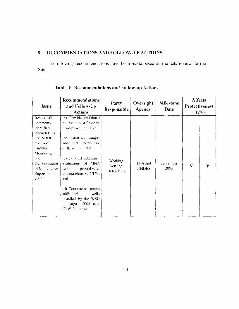
9. RECOMMENDATIONS AND FOLLOW-UP ACTIONS
The fol lowing recommendations have been made based on the data review for theSite.
Table 3: Recommendations and Follow-up Actions
Issue
Resolve allcoir meritsidentifiedthrough EPAand NHDESreview of"AnnualMonitoringandDemonstrationof ComplianceReport for2004"
Recommendationsand Follow-Up
Actions(a) Provide additionalnotif icat ion of PropertyOwners w i t h i n GMZ;
(b) In s t a l l and sampleadd i t i ona l monitoringwells w i t h i n GM7;
(c) Conduct additionalevaluations of MNAw i t h i n grounclwaterdowngradicnt of CTW;and
(d) Con t inue to sampleadditional wellsinstalled by the WSDin August 2005 nearCTW-20 transect.
PartyResponsible
WorkingSettling
Defendants
OversightAgency
HPA andNHDES
MilestoneDate
September2006
AffectsProtectiveness
(Y/N)
N Y
24

10. PROTECTIVENESS STATEMENT
The remedy is considered protective in the short-term; however in order for theremedy to he protective in the long-term, follow-up actions need to be taken. Long-termprotectiveness wi l l be achieved once additional notification of property owners wi th inthe Groundwater Management Zone (GMZ) is provided in accordance with currentState requirements, newly instal led shallow and bedrock monitoring wells are sampledto confirm a "clean-edge" along the northern boundary of the GMZ, and the recentanomalies identified at the CTW near the CTW-20 transect are more f u l l y understoodthrough the monitoring of new wells installed by the WSD in August 2005.

11. NEXT REVIEW
The next five-year review for the Somersworth Sanitary Landfill Superfund Site isrequired by September 2010, l ive years from the date of this review.
26

ATTACHMENT A
LIST OF DOCUMENTS REVIEWED

ATTACHMENT A
LIST OF DOCUMENTS REVIEWED
Beak International Incorporated (Beak). 1998. Design Investigation Report for theP lot Study and Site Groundwater Monitoring Program. Remedial Design for PreferredRemedial Action at the Somersworth Sanitary Landiill Superlund Site, New Hampshire.Draft Report. Ju ly 1998.
Beak International Incorporated and GeoSyntec Consultants International, Inc.(Beak and GeoSyntec). 1999. Preferred Remedial Action 100% Design andDemonstration of Compliance Plan. Somersworth Sanitary Landfill Superfund Site,New Hampshire. Final Report. 23 April 1999.
GeoSyntec Consultants International, Inc. (GeoSyntec). 2000. 100% Design Update# . Preferred Remedial Action 100% Design and Demonstration of Compliance Plan.Somersworth Sanitary Landfill Superfund Site, New Hampshire. 17 Ju ly 2000.
GeoSyntec Consultants International, Inc. (GeoSyntec) 200la. Sampling andAnalys i s Plan (SAP) for Groundwater Monitoring During Preferred Remedial Action;Part 1 of 2, Field Sampling Plan. 19 March 2001.
GeoSyntec Consultants International, Inc. (GeoSyntec) 200Ib. Chemical TreatmentWall Construction Completion Report. Draft. 30 May 2001.
GeoSyntec Consultants International, Inc. (GeoSyntec) 2003. Annual Monitoringard Demonstration of Compliance Report for 2002. DRAFT. 31 January 2003.
GeoSyntec Consultants International, Inc. (GeoSyntec) 2()04a. Annual Monitoringand Demonstration of Compliance Report for 2003. DRAFT. 2 March 2004.
GeoSyntec Consultants International, Inc.(GeoSyntec) 2004b. Operations andMaintenance Plan for Preferred Remedial Action at the Somersworth Landfi l lSuperlund Site. 30 April 2004.

GeoSyntec Consultants International, Inc. (GeoSyntec) 20()4c. Annual Monitoringand Demonstration of Compliance Report for 2004 (Volumes I and I I ) . Draft. 14March 2005.
GeoSyntec Consultants Intemational, Inc. (GeoSyntec) 2005. Draft RemedialAction Report for Preferred Remedial Action at the Somersworth Sanitary LandfillS jperfund Site. 15 March 2005.
United States Environmental Protection Agency New England (Region I) (EPA).1994. Record of Decision, Somersworth Sanitary Landfill Superfund Site.
United States Environmental Protection Agency New England (Region I) (EPA).1995. Consent Decree for Remedial Design/Remedial Action at the SomersworthSanitary Landfi l l Superfund Site, Somersworth, New Hampshire.

ATTACHMENT B
FIGURE 1 - SITE LOCATIONAND
FIGURE 2 - SITE PLANAND
TABLE 2.3 FROM 2004 ANNUAL REPORT
A.I

\X
.\ N K W HAMFSHIR1-; A.s"'"'"' - Somersworth
y\A (j- KuikiiUili.il:
i HilMi.imuiMl \< • • :, ^ — t
'-i. J..x
MASSACHUSETTS
- <%> \\ ̂
,:%, *\ V*" \- ' '•• -'•'-"'• '
<&.<-4'^y>-C- -' ' ' '.I /. •:-;•.
c^ s^-
Route 16A West High St. a:/-•'
,;/ <<<".;
-,«'.\ <^("*v,;
•' ^ X' ":- e^^V'.X^" '^-/^
.,'V. ..,-A^F ,^
$^:' T'^^7^<r.
, "O : --•.-" •;>', ^.\\0C^#'cj.,/; .°-%';> - ••' ... ,v '- 'V V& $}
.;-;••.*•,/-•'' \.
,̂4^,̂
;v . . . - •^So^
City ofSomersworth
,-. ,- ft ^ •••: ^H^V^'•»r c^-:-'' 'U^w. ^ ^s•-- ^/-' ^'^t^'W?^ V
,-,• / ! . Vv^' -'"
M
'^.S'<\
'(
i
Somersworth Sanitary ILandfill Superfund Site \
T'' .:
1 O
A-.^/r ' -,..- -"• ': ,C.
<2".r5 0 0 l O O O t t
' \:;^>
•',' 'S-1'-'-• ? %Site Location Map
Somersworth Landfill Superfund Site, Somersworth, NH
June 2005 Figure: 1 :̂oCONSULTANTS


TABLE 2.3GROUNDWATER DATA FOR OBJECTIVE IA - EVALUATE
GROUNDWATER PASSING THROUGH CTWSomers>vorth Sanitary Landfill Superl'und Site, New Hampshire
GeoSvntec Consultant*
Well 1 0CTW-2JL
Mean 2001Mean 2002Mean 2003Mean 2004CTW-2:.U
Mean 2001Mean 2002Mean 2003Mean 2004
Sample Date28-Mar-Ol26-Apr-0117-Jul-Ol16-Oct-Ol25-Apr-0224-Jul-0214-Oct-0221 -Apr-0323-Jul-0315-0ct-0320-Apr-042!-Jul-0420-Oct-04
28-Mar-Ol26-Apr-0117-Jul-Ol16-Oct-Ol16-Oct-Ol25-Apr-0224-.kil-0215-0ct-02
21 -Apr-0323-Jul-0315-Oct-0315-0ct-0320-Apr-0421-Jul-0420-Oct-04
QA/QCSampleType
—~——-——-——-----
—--
Field Duplicate—-——--—
Field Duplicate---
1,1-DCE1*
(US/I-)5 . 0 L J5.0 U5.0 U5.0 U5.0 U5.0 U5.0 U5.0 U5.0 U5.0 LI5.0 U5.0 U5.0 U0.4X0.4H0.4$0.375.0 I)5.0 U5.0 U5.0 LJ5.0 U5.0 U5.0 U5.0 U5.0 U5.0 LI5.0 1;5.0 L:5.0 L;5 . OU5.0 LI0.48OAK0 4H0.37
cDCE70*
(MB/105.0 1;5.0 u5 . 0 L J5.0 U5.0 U5.0 LJ5.0 U5.0 U5.0 LJ5.0 U5.0 LI5.0 U5.0 U(L 660.660.660.495.0 U5.0U5.0 LI5.0LJ5.0 U5.0 U5.0 LJ5.0 LI5.0 U5.0 U5.0 LJ5.0 i;
4781
5.0LJ0.660.660.6643
tDCE100*
(H8/U5.0 U5.0 LI5.0 U5.0 U5.0 U5.0 U5.0 U5.0 U5.0 LJ5.0 U5.0 U5.0LJ5.0 U0. 570.570.570.505.0 U5.0 U5.0 LJ5.0 U.5.0 U5.0LJ5.0 LI5.0 LJ5.0 LJ5 .0U5.0U5.0 U5.0 U5.0 U5 . 0 U0.570.570.570.50
PCE5*
(Hg/D5.0 U5.0 U5.0 U5.0 U5.0 U5.0 U5.0 U5.0 U5.0 U5.0 U5.0 U5.0 U5.0 U0.500. 500.500.315.0 U5.0 U5.0 U5.0 L'5.0 LJ5.0 LJ5.0 U5.0 U5.0 LJ5.0 U5.0 U5.0 U5.0 U5.0 LJ5.0U0.500.500.500.31
rcE5*
(ug/L)5.0U5.0 U5.0 LJ5.0 U5.0 U5.0 LJ5.0 U5.0U5.0 U5.0 LJ5.0 U5.0U5.0 U0.540.540.540.485.0LJ5.0 U5.0LJ5.0U5.0 LJ5.0LJ5.0 LJ5.0 U5.0 U5.0 LJ5 .0U5.0 LJ5.0U5.0 U5.0 U0.540. 540.54OAK
vc2*
(HS/L)2.0 U2.0 U2.0 U9.7
2 .0U2 . 0 L J2.0LJ2.0 U2.0 U2.0U2.0 U
152.0 LJ3.80. 790. 795.3
2 .0LJ2.1
2.0 U2.0U2.0 U
2.12.0 U2.0 LJ2.0 LJ2.0 U2.0 U2.0 U
4364
2.0 LJ1.21.2
0. 7936
TR0057Task S5.'Annual Report 2004Table 2.3 OKjixtive I A data 2004 Pauc 1 of 4
DRAFT2'2 1/2005

TABLE 2.3GROUNDWA PER DATA FOR OBJECTIVE 1A - EVALUATE
GROUNDWATER PASSING THROUGH CTWSomersworth Sanitary Landfill Superfund Site, New Hampshire
GeoSvnlec Consultants
Well 10CTW-33L
Mean 2001Mean 2002Mean 2003Mean 2004CTW-33U
Mean 2001Mean 2002Mean 2003Main 21:04
Sample Date28-Mar-OI28-Mar-Ol25-Apr-Ol17-Jul-Ol17-Oct-Ol25-Apr-0223-Jul-021 5-Oct-0221 -Apr-0323-Jul-0315-Oct-0320-Apr-0421-Jul-041 9-Oct-04
28-Mar-Ol25-Apr-Ol17-Jul -Ol17-Oct-Ol25-Apr-0223-Jul-02l5-Oct-0221 -Apr-0323-Jul-031 5-Oct-0320-Apr-042l-Jul-0420-Oct-0420-0ct-04
QA/QCSampleType
Field Duplicate—-——-——----——
—-——-——---—-——
Field Duplicate
1,1-DCE7*
(m;/L)5.0 U5.0 U5.0 U5.0 U5.0 U5.0U5.0 U5.0U5.0 U5.0 U5.0 U5.0U5.0 U5.0 U0.480.480.480.375.0 U5.0 U5.0 U5.0 U5.0 U5.0 U5.0 U5.0 U5.0U5.0 U5.0 U5.0 U5.0 U5.0 U0.480.480.480.37
cDCE70*
(ftg/L)8.68.8
5 . 0 U5.0 U5 .0U5.0 U5.0 U5.0 U5.0 U5.0 U5.4
5.0 U5.0 U5.0 U0.660.66? 1
0.495.0 U5.0 U5.0U5.0U5.0 U5 .0U5.0 U5.0 U5.0 U5.0 U5.0 U5.0 U5.0 U5.0 U0.660.660.660.49
tDCE100*
(HS/M5.0 U5. Oil5.0 U5.0 U5 . 0 U5.0 U5.0 U5.0U5.0 U5.0 U5.0 U5.0 U5.0 U5.0U0.570.570.570.505 . O U5.0 U5.0 U5.0 U5.0 U5.0U5.0U5.0 U5. Oil5.0 U5.0 II5 .0U5.0 U5.0 I0.570.570.570.50
PCE5*
(Hg/L)5.0 U5.0U5.0 U5.0 U5.0 U5.0 U5.0 U5.0 U5.0 U5.0 U5.0 U5.0 U5.0 U5.0 U0.500.500.500.315.0 U5.0 U5.0 I"5.0 U5.0 U5.0 U5.0 U5.0 U5.0 U5.0 U5.0 U5.0U5.0 U5.0 U0.500.500.500.31
TCE5*
(MB/L)5.0 U5.0 U5.0 U5.0 U5.0 U5.0 U5.0 U5.0U5.0 U5.0 U5.0U5.0 U5.0 U5.0 U0.540.540.540.485.0 U5.0U5.0 U5.0U5.0U5.0 U5.0 U5.0 U5.0 U5.0U5.0U5.0U5.OU5.0U0.540.540.540.48
vc2*
(HS/L)8.38.72.52.1
2.0 U2.0 U2.0 U2.0 U2.0 U2.0 U3.8
2 . 0 U2.0 U2.0 U
l.fi0. 791.8
0.502.0 U4.8
2.0 U2.0 U2.0 U2.0 U2.0U2.0 U2.0 U2.0U2.0 U2.0 U2.0 U2.0 U2.10.790.790.50
TR0057Task 85 'Annua l Report 2004Table 2..' Orjecuve I A dala 2004 Pu»e 2 of 4
DRAFT2/21/2005

TABLE 2.3GROUNDVVATER DATA FOR OBJECTIVE 1A - EVALUATE
GROUNDVVATER PASSING THROUGH CTWSomersworth Sanitary Landfill Superf'und Site, New Hampshire
GcoSvntcc Consultants
Well IDCTW-43L
Mean 2001Mean 2002Mean 2003Mean 2004CTW-43L'
Mean 2001Mean 2002Mean 2003Mean 2004
Sample Date28-Mar-OI25- Apr-0117-Jul-Ol17-Oct-Ol24-Apr-0224-APr-0223-Jul-021 6-Oct-022 1 -Apr-032 1 -Apr-0323-Jul-031 5-Oct-031 5-( )ct-0320-Apr-0421-Jul-0420-Oct-04
28-Mar-OI25-Apr-Ol17-Jul-Ol17-Oct-Ol24-Apr-0223-Jul-02l.vOct-0221 -Apr-0323-Jul-03LvOct-032()-Apr-042 l - Ju l -0420-Oct-04
QA/QCSampleType
—---—--
Field Duplicate——
Field Duplicate--——
Field Duplicate----
—--——---—-----——
1,1 -DCE7*
(HS/L)5.0 U5.0 U5 .0U5 . 0 U5.0U5.0 U5.0U5.0 U5.0 U5.0U5.0 U5.0 U5.0U5.0 U5.0 U5.0 U0.480.480.480.375.0 U5.0 U5.0 U5.0U5.0 U5 .0U5.0U5.0 U5.0 U5.0U5.0 U5.0 U5.0 U0.480.480.480.37
cDCE70*
(Hg/L)5.0 U5.0 L'5.0 U5.0 U5.0 U5.0 U5.0 U5.0 U5.0 U5.0 U5.0 U5.0 U5.0 U5.0 U5.0 LI5.0 U0.660.660.660.495.0 U5.0 U5.0115.0 U5.0 U5.0 U5.0 U5.0U5.0 U5.0 U5.0 U5.0 LJ5.0 U0.660.660.660.49
tDCK100*
(ns/U5.0 U5.0 U5.0 U5.0 LI5.0 U5.0 LI5.0 LI5.0 U5.0 LI5.0 U5.0 L;5.0 U5.0 U5.0 U5.0115.0 U0.570.570.570.505.0 U5.0 U5.0 LJ5.0 U5.0 LI5.0 LI5.0 U5.0 U5.0 U5.0 U5.0 L:5.0 u5 . 0 U0.570.570.570.50
PCE5*
(HS/L)5.0 U5.0 U5.0 U5.0 U5.0 U5.0 U5.0 U5.0 U5.0 U5.0 U5.0 U5.0 U5.0 U5.0 U5.0 U5.0 U0.500.500.500.315.0 U5.0 U5.0 U5.0 U5.0 U5.0 U5.0 U5.0 U5.0 U5.0 U
TCE5*
(H8/D5.0 U5.0 U5.0 U5.0LJ5.0 U5.0U5.0 LJ5.0 U5.0 LJ5.0 U5.0 LJ5.0 LJ5.0 U5.0 U5.0U5.0 U0.540.540.540.485.0U5.0U5.0 U5.0 U5.0U5.0U5.0 U5.0U5.0 U5.0 LJ
5.0 U 5.0 U5.0 U , 5.0 U5.0 U 5.0U0.50 0.540.50 0.540.50 0.540.31 0.48
vc2*
(MS/L)2.0 U2.0 U2.0 U2.0 U2.0 U2.0 U2.0LJ7.2
2.0U2.0 U2.0 U2.0 U2.0 U2.0U2.0U2.0U0. 792.9
0.790.502.0 U2.0 U2.0 U2.0 U2.0 U2.0 U2.0LJ2.0 U2.0 U2.0 LJ2.0 U2.0 U2.0 U0.790.790.790.50
rR()057 Task XS A n n u a l Keporl 2004Table 2.3 Ob]ccme I A i la la 2004 P a u e 3 o f 4
DRAFT2/21/2005

TABLE 2.3 GeoSvntec ConsultantsGROUNDWATER DATA FOR OBJECTIVE 1A - EVALUATE
GROUNDWATER PASSING THROUGH CTVVSomersworth Sanitary Landfil l Supi-rlund Site, New Hampshire
Notes:- All wells shown in this table were also sampled on February 15, 2001 but samples were concluded to he notrepresentative and resul ts are not shown (R-qual i f ied) .U - indicates compound not detected; associated value is the q u a n t i t a t i o n l imi t(.tg/L - micrograms per l i t reCTW - clumieal treatment wall- ICL - Inter im Cleanup LevelsAnnual mean ch lo r ina t ed cthenc (CE) concentrations were calculated for 2001 using the Apr i l . J u l y and ( ic loher 2001
data. For subsequent years, the April, July and October data for that year arc used to calculate the mean, so thateach annual mean is based on data from three seasons. When a Held dupl ica te was conducted, the data lor theduplicates were averaged first to obta in a single value for that sampling event, which was then used to ca lcu la te the meanfor the year.
The method detection l i m i t (MDL) for the appropriate year was substituted for non-dcteets. If a samplewas di luted, the MDL was m u l t i p l i e d by the di lut ion factor.- MDLs:
2001 - 2003 Trichloroethene (TCE) - 0.54 ug/LTelrachlorocthene (PC 'E) = 0.50 ug/Lcis - l ,2 -d ich lo roe thene (cDCE) = 0.66 ug/Ltrans-1 ,2-d ieh loroe thene (tlX'E) = 0.57 ug/L1,1 -diehloroethene ( 1 . 1 -DCE) = 0.48 ug/LV i n y l Chloride ( V C ) - 0.79 ug/L
2004 Trichloroethene (TCE) = 0.484 ug/LTctrachloroethenc (PCE)= 0.305 ug/Lcis-1.2-diehloroethene (cDCE) - 0.487 ug/Lt rans - l ,2-dichloroethene ( t D C E ) " 0.50 ug/L1.1-diehloroethene [ 1.1-DCE) = 0.371 ug/LVinyl Chlor ide ( V C ' ) ~- 0.503 ng/L
TR0057Tnst X5 A n n u a l Report 2004 DRAFT'Table 2.3 Ot jecmc 1A d;i i ; i 201)4 Page 4 of 4 2/21/2005

ATTACHMENT C
CITY OF SOMERSWORTH GROUNDWATER PROTECTIONDISTRICT ZONING ORDINANCE
CITY OF SOMERSWORTH, NEW HAMPSHIRE
CHAPTER 19-ZONING ORDINANCE
SOMERSWORTH
ADOPTED BY SOMERSWORTH CITY COUNCIL - AUGUST 30,1989
AMENDED: MARCH. 1990AUGUST, 1990SEPTEMBER, 1990JANUARY, 1991APRIL, 1991 MAY,1991SEPTEMBER, 1991MAY, 1992SEPTEMBER, 1992JULY, 1993SEPTEMBER, 1993FEBRUARY, 1994APRIL, 1994JULY,1994FEBRUARY, 1995
OCTOBER, 1995JANUARY, 1996JULY 15, 1996JUNE 2, 1997APRIL 6, 1998JUNE 1, 1998JANUARY 18, 1999OCTOBER 19,1999JANUARY 10, 2000APRIL 17, 2000AUGUST 14,2000DECEMBER, 2000MARCH, 2001MAY 21, 2001OCTOBER 7, 2002
OCTOBER 21. 2002MAY 3, 2004MARCH 21, 2005

CITY OF SOMFRSWORTH
CHAPTER 19 ZONING ORDINANCE
Amended March. 1990:Pages 1. 2, 3,13,14, 52, 56,60through 74. 83. 84, 85. Also, tables 4 . A . I ; 4.A.2; 4.A.3: 4.A.4;4.A.5. Note #5; 5.A.1.:5.A.2.
Amended August. 1990:Section 7, pages 16 thru 23.
Amended September, 1990:Section 17, pages 63 thru 67. Table 5.A.I and Table 5.A.I Notes.
Amended January 7. 1991:Section 20, page 89 - Zoning Board of Adjustment.
Amended April 1, 1991:Section 18.C.4.C. - Political Signs.
Amended May 20. 1991:Section 3.D., Page 5 - Commercial/Industrial District; Table of Uses, Tables 4.A.2; 4.A.3;4.A.4;4.A.5; 5 .A.I .
Amended September 16. 1991:Section 12. pages 46 thru 54 - Wetlands Conservation Overlay District.
Amended May 4. 1992:Sectior 13. pages 53 thru 58 - Historic District.
Amended September 21,1992:Sectior 8, pages 24. 26 and 28 - Home Occupations.
Amenced July 26. 1993:Section 21, page 93 - Definitions; Table 4.A.4.
Amenc.cd September 7. 1993:Section D.2., page 5 - Commercial/Industrial District.
Amenocd February 28, 1994:Section 3. D.2., pages 5 & 6 - Commercial/Industrial District. Section14, pages 60 thru 62 - Sexually Oriented Businesses (new). Section 18.page 71 on (19 pages) - Sign Regulations. Table of Uses - Table 4. A.5(at end of chapter)
Amended April 4. 1994:Table of Uses - Table 5.A.I and Table 5.A.I Notes.

Amended July 18. 1994:Sections 11.B.4. & 11.B.5. (page 39); l l .B.8 . f .& 11.B.9. (Pages 42 & 43); 1 I.e.(Pages 45 &45A).
Amended February 21, 1995:All pages renumbered to correspond with section numbers.Table of Contents.New Section added - "Section 15, Commercial Node District" (pages 15.1 thru 15.3).Section 15 through Section 23 renumbered to Section 16 through Section 24.Add Section 3.B.I6. (page 3.3).Add Section 3.D.8. (page 3.9).Section 20.A.I . (page 20.1).Section 20.B.3. (pages 20.1 & 20.2).Section 20.B.3.H. (page 20.3).Section 22 (pages 22.1 thru 22.9).Tables .5.A.1&5.A.2
Amended October 2. 1995:Added new Section 11 - Excavation of Earth Products (pages 1 1 . 1to 11.4)Section 1 1 through Section 24 renumbered to Section 12 through Section 25.
Amended January 10. 1996:Add Section 3.B. 15 (page 3.3).Add new Section 16 - Recreation District (pages 16.1 thru 16.3).Renuimer all sections and pages after section 16 to reflect this change.Section 24 (page 24.2).Table 5.A. 1 Notes (page 8).
Amended July 15, 1996:Delete Section 20 - Landscaping and Buffer Requirements, in its entirety.Delete Section 22 - Circulation and Parking Regulations and replace with Section 21 - CirculationAnd Parking Regulations (page 2 1 . 1 ) .Renumber Section 23 through Section 26 to Section 22 through 25.
Amended June 2. 1997:Section 8.D. (page 19:18)Section 8.F.3. (page 19:18)Section 8.F.6. (page 19:19) delete second paragraphTable -c.A.3 & Note #6 (page 19:77)
Amended April 6. 1998:Sectior 23 - Definitions (pages 68 and 70)Table -.A.3 and 4.A.5Amended June 1. 1998:Section 20 Sign Regulations - page 60.
Amcnccd January 18. 1999:Table 4.A.4 and 4.A.5

Amended October 19, 1999:
Added new Section 23 Naming of Public Streets and Rights of Way - pages 72-75
Renumbered Section 23 Definitions to Section 24 - pages 76-82. Renumbered Section 24Administration & Enforcement to Section 25 - page 83. Renumbered Section 25Interpretat on, Conflicts & Separability to Section 26 - pages 84&85.
Amended January 10,2000:Section 8 Home Occupations - pages 18,19 & 21.Section 10 Groundwatcr Protection District - pages 25 & 26.
Amended April 1.2000:Section 8 Home Occupations - pages 18,19& 21.
Amended August 14, 2000:Section 9 - Manufactured Mousing District - pages 23 thru 24C. Table 4.A.5-
pages91 &92.
Amended December 11. 2000:Section 12 - Flood Plain District - pages 32 thru 38A.
Amended March 19. 2001:Section 3.A. - Districts - page 1.Section 3.8.7. (deleted) - page 2.Section 3.D.10. and 3.D.10.a. - (new) - page 7.Section 24.NN. and 24.PP (delete) - page 79 and 80.Tables 4 .A.I . through 5.A.2 - pages 86 through 94.
Amended May 21,2001:Section 19.3.A. - Districts - page 1.Section 19.3.B.14. - Purpose of Districts - page 3.Section 19.3.D.I 1. - District Boundaries - page 7.Section 1 C >.3 .D.12 . - District Boundaries - pages 7 & 8.Section 19.21. - Circulation & Parking Regulations - page 70.Tables 4.A.l,4.A.2,4.A.3,4.A.4,4.A.5^5.Ari - pages 85 thru 92.
Amended October 7. 2002:Added new Section 24 Common Driveway Subdivision - pages 78 and 79.Renumbered Section 24 thru Section 26 to Section 25 thru Section 27.
Amended October 21. 2002:Table 4.A.3. - page 90

Amended 5/03/2004:Section 7, Cluster Subdivision - pages 12 thru 17. Changed Cluster Subdivision to readConservation Residential Development throughout Section.Sections 20.D.2.a, 20.D.2.C, 20.D.2.C- page 68.Section 20.D.4-page 70.Section 25, Definitions - pages 80 thru 84.Added new Section 26. Telecommunication Facilities - pages 86 thru 93.Amended Table of Uses (Table 4.A.3). page 98.Amenccd Table of Uses (Table 4.A.5). pages 101 & 102.
Amended 3/21/2005:Section 19.12.A. Flood Plain District. Applicability - page 34.Section 19.14.H.2. Historic District, Appeal Process -page 52.Section 19.20.B. 13. Sign Regulations, Flashing Sign -page 61.Section 19.20.C.2.C. Sign Regulations-page 63.Section 19.20.C.4.a. Sign Regulations - Banner Signs- page 64.Section 19.25.Y. Definitions, Dwelling Unit - page 82.Section 19.25.DD. Definitions, Frontage - page 82.Section 19.27.C. & 19.27.R. Administration & Enforcement-page 94.Table 4.A. 1.- page 96.

Section 10 Groundwater Protection District
19.10.A. AUTHORITY. In accordance with New Hampshire Revised Statutes Annotated (RSA)Chapter 4-C:22 I I I , as the same may be subsequently amended, the City of Somcrsworthhereby adopts the following Groundwaier Protection District.
19.10.B. PURPOSE. The purpose of this ordinance is, in the interest of public health, safety andgeneral welfare, to protect, preserve and maintain the existing and potential groundwatersupply and groundwater recharge areas wi th in the known aquifer from adversedevelopment, land use practices or depletion, and to allow for the restoration of degradedground water by the establishment of a "Ground Water Management Zone".'
19.10.C. LOCATION.19.10.C.I . The boundaries of the Groundwater Protection District shall be the outermost edge of
the out wash deposits of the "Lily Pond Aquifer", as designated in the "Report onAquifer Defini t ion Lily Pond Aquifer Somersworth, New Hampshire," prepared byBCI Geonetics, Inc., and included in the Water Master Plan Update dated Junel984.The Ground Water Management Zone is designated by the Ground WaterManagement Zone Overlay Map included in the Preferred Remedial Action 100%Design and Demonstration of Compliance Plan prepared by Beak International, Inc.and Gco Syntec Consultants International, Inc. '
19.10.C.2. When the actual boundary' of the Groundwater Protection District is in dispute by anyowner or abutter actually affected by said boundary, the Planning Board, at theowncr/abuttcr's expense and request, may engage a professional geologist orhydrologist to determine more accurately the precise boundary of said GroundwaterProtection District.
19.10.D. APPLICABILITY.19.10.D.I . All land use activities and development conducted within the Groundwater Protection
District shall be regulated by the standards established herein.
19.10.D.2. The standards established herein shall constitute the rules of an overlay /one and shallbe superimposed over other /oning districts or portions thereof. The provisions hereinshall apply in addition to all other applicable ordinances and regulations. In the eventof a conflict between any provision herein and any other ordinance or regulation, themore restrictive requirement shall control.
19.10.E. DEFINITIONS.
19.10.E. 1. Animal Feed Lots. A plot of land on which 25 livestock or more per acre are kept forthe purpose of feeding.
19.10.E.2. Groundwater. Water in the subsurface /one at or below the water table in which allpore spaces are filled with water.
19.10.E.3. Groundwater Management Zone (GMZ). The subsurface volume in which groundwater contamination associated with a discharge of a regulated contaminant iscontained. (State of NH Groundwatcr Protection Rules - L:nv - WS410.)2
'Amended 1 10/2000.- P:i««1 1 ; 1 0.-9000 19'?7

19.10.E.4. Hazardous and Toxic Materials. Those materials that pose a present or potential hazardto human health and the environment when improperly stored, transported ordisposed of. These materials include those listed in the New Hampshire HazardousWaste Regulations. Third Edition. Appendixes 1-4,1985, New Hampshire Dept. ofEnvironmental Services, Concord, as the same may be subsequently amended.
19.10.E 5 Impervious Surface. A surface covered by any material (such as pavement, cement,roofing) that prevents surface water from penetrating the soil directly.
19.10.E.6. Ecachable Wastes. Waste materials including solid wastes, sewage, sludge, andagricultural wastes that are capable of releasing waterborne contaminants to thesurrounding environment.
19.10.E.7. Solid Waste. Discarded solid material with insufficient l iquid content to be freeflowing. This includes but is not limited to rubbish, garbage, scrap materials, junk,refuse, inert f i l l material and landscape refuse.
19.10.F. PROHIBITED USES. The following uses are expressly prohibited from the GroundwatcrProtection District:
19.1 O . F . I . Within the Lily Pond Aquifer '
19.10. F . I . a . The disposal of solid waste including landfills and sewage lagoons, exceptingdisposal of stumps and brush;
19.10.F. 1 .b. Storage of road salt or other deicing chemicals except in a property constructedshelter for use on site;
19.10.F.I .c. Dumping of snow containing road salt or other dcieng chemicals;19.10.F.l .d. Motor vehicles service or repair shops:19.10.F.I.e. Junk and salvage yards;19.10.F. l . f . Animal fecdlots;19.10.F.I .g Commercial or industrial handling, disposal, storage or recycling of hazardous or
toxic materials or wastes; and19.10.F. 1 .h Underground storage or petroleum or any refined petroleum product. All existing
underground tanks, including those under 1,100 gallons, must be registered withthe Somersworth Fire Department within six months of the enactment of thisregulation. Existing tanks over 1.100 gallons are subject to Water Supply andPollut ion C'ontrol Commission regulation, pursuant to New Hampshire Code ofAdministration No. W541 1.
19.10.F.2. Within the Groundwater Management Zone:19.10.F.2.a. The requirements, restrictions, and prohibition of the underlying Zoning District
shall continue to apply to the extent that they arc not inconsistent with theprovision of this section; and
19.10.F.2.b. Pumping of ground water from any wel l , trench, sump or other structure forresidential, irrigation, agricultural or industrial purpose is prohibited
19.10.Ci. SPECIAL CONDITIONS. The following conditions shall apply to all uses in theGroundwater Protection District:
Added 1/10/2000.Passed 1MO'2000 .
19:28

19.10.G 1. A lot shall not be rendered more than ten percent (10%) impervious. A proposeddevelopment plan which wil l incorporate a stormwater drainage plan, approved by theCity of ^ : ; , j r - A i > r . h Planning Board and prepared by a professional engineer certifiedto practice in the State ofNcw Hampshire shall be provided. The plan sha II provide forthe . i-> ic retention and percolation of all development generated stormwater :unui:from a ten (10) year storm. Furthermore, the stormwatcr drainage p]an shali providefor the intcring of parking area runoff to remove oil, gasoline and other impuritiesprior to retention and percolation of the runoff;
19.10.G.2. Development or sand use activities proposed within the ( : i \ . m i ( i \ \ a t v . - i ProtectionDistrict shall be connected to the municipal sewage disposal system and the municipalwater system;
19.10.G.3. Any use retaining less than thirty percent (30%) of lot area, regardless of size, in itsnatural vegetative state with no more than minor removal of existing trees andvegetation shall require a special permit;
19.10.G.4. Mining operations, including sand and gravel removal, shall require an Earth RemovalPermit, pursuant to New Hampshire Revised Statutes Annotated Chapter 1 ^ f - l whichis herein incorporated by reference. Such excavation or mining shall in no case becarried out within eight (8) vertical feet of the seasona i high water table: and
19.10.G.5. The storage of petroleum or related products in a freestanding fuel oil tank within oradjacent to a residential structure which is used for the normal heating of said structureshall be permitted pursuant to the conditions outlined in subsection i! below, and allapplicable state regulations. All tanks shall be protected from internal and externalcorrosion and shall be of a design approved by the Somersworth Fire Department. Alifreestanding tanks shali be placed on an impermeable surface such as a concrete pad.No tank may be abandoned in place. A tank shall be disposed of after emptied of allhazardous materials if it has been out of service for a period in excess of twelve (12)months. The product and the tank shall be disposed of by the property owner asdirected by the Somersworth Fire Department and all applicable state laws. All leakingtanks must be emptied by the owner or operator within twelve (12) hours afterdetection of the leak and removed by the owner and or operator as per above.
I9.10.H. ADMINISTRATION.19.1 0 .31.1 . Dcvc,opmcnt or land use activities proposed within the Groundwater Protection
District that require a spec ial permit, as provided in subsection (< above, shall bercvcwcJ by both !:v Planning Board and the Somersworth ConservationCommission. The Planning Board shall either approve, conditionally approve ordisapprove a special permit only after it determines that the proposed land usedevelopment and or activities comp .y with the purpose of this regulation In makingsuch a determination, the Planning Board shall give consideration to the simplicity,reliability and feasibility of the control measures proposed and the degree of threat toy uu/AJ \ j%: quality if the control measures failed.
19.10.H.2. Development or land use activities proposed within the Groundwater ProtectionDistrict that require subdivision or site plan approva i from the Planning Board shallalso be reviewed by the Somersworth Conservation Commission. The Planning Boardand the Conservation Commission shail verify that the proposed activity will conformto the provisions of this regulation ordinance prior to action by the Planning Board toapprove, conditionally approve or disapprove the application.
19:29

19.10.H.3. The Building Inspector shall not issue a building permit for development or land useactivities until such time as he/she verifies that the proposed activity will conform tothe provisions of this ordinance. The Bui lding Inspector may consult with the PlanningBoard and or Conservation Commission as he/she deems necessary.
19.10.11 4. Land use activities that do not require the receipt of Panning Board approval orbuilding permits shall nonetheless be subject to the requirements and standardsestablished herein.
19.10.H.5. A ! m i i < * i i c u U r j i L study may be required by the Planning Board and or theConservation Commission to investigate the impacts a proposed development or landuse activity will have on an existing or future L I I H I I K I ' A U ' ^ - I supply. A qualifiedprofessional :r J .nnuu^ t or geologist shall be chosen by the City of SI> : - .KTS\S . . > : ih andthe applicant for approval shall pay any and all costs incurred.
19.10.J :.6. For all frcestand ing fuel oil tanks as permitted per Section 7. I ' . . the property ownersha 1 fie with the City of Somcrsworth the following information prior to theinstallation of a tank:
19.10.; .6.a. The si/c of the tank;
19.10., .6.b The type of tank;
19.10.1 l.6.c. The type of material being stored and its quantity;
19.10.: i 6.d. The location of each tank on the premises, complete with a sketch map; and
19.10.H.6.C. The age of each tank.
19.10.1 ENFORCEMENT. If the Planning Board and or the Building Inspector finds that any ofthe requirements and standards established herein are in violation, the Building Inspectorshall order the owner, in writing, to make such corrections as he she deems necessary tobring the development and act ivi t ies into compliance with the provisions of thisordinance. Such order shall be complied with wi thin twenty-four (24) hours of the originalnotice to the owner. Where the owner fails to comply with the order of the BuildingInspector, a fine of one hundred dollars (SI00) per day,or the maximum amount which isauthorized by statute, may be levied against said owner. The fine shall be retroactive andshall begin to accrue on the date on which the property owner receives written notice fromthe Building Inspector that he she is in violation of th is ordinance.
19:30
