flecs ct manual v12-1 (1)
TRANSCRIPT

1
FLECS CT Users Manual
Software Version 1.2
2
1 FLECS Concepts ......................................................................................................... 5
1.1 FLECS System Concepts .................................................................................... 5
1.2 FLECS Display ................................................................................................... 5
1.2.1 FLECS Display Screen ............................................................................... 5
1.2.2 FLECS Display Touch-screen .................................................................... 6
1.2.3 FLECS Display Keypad .............................................................................. 6
1.2.4 FLECS Display Power Indicator ................................................................ 7
2 FLECS CT Concepts................................................................................................... 8
2.1 FLECS CT Interface Organization ..................................................................... 8
2.2 Constantly Visible Display ................................................................................. 8
2.3 Context Dependent Display ................................................................................ 9
2.4 Context Menu...................................................................................................... 9
3 Keypad Navigation ................................................................................................... 10
3.1 FLECS CT Desktop .......................................................................................... 10
3.2 Key Hints .......................................................................................................... 10
3.2.1 Desktop Key Hints .................................................................................... 10
3.2.2 Key Hints in Menus .................................................................................. 11
3.3 CTRL Key ......................................................................................................... 12
4 Entering Calibration Points ....................................................................................... 12
4.1 Add Calibration Point ....................................................................................... 12
4.1.1 mA Value Entry ........................................................................................ 12
4.1.2 Value Entry ............................................................................................... 15
4.2 Delete Calibration Point .................................................................................... 17
5 Sensor and Actuator Connection Selection............................................................... 18
5.1 Overview ........................................................................................................... 18
5.1.1 Current Selection ...................................................................................... 18
5.1.2 Changing the Selection ............................................................................. 19
6 Weight Display ......................................................................................................... 20
6.1 FLECS CT Weight Measurement ..................................................................... 20
6.2 Current Weight.................................................................................................. 20
6.3 Limiting System Status ..................................................................................... 21
6.4 Weight Display Configuration .......................................................................... 21
6.4.1 Load Pin Setup .......................................................................................... 21
6.4.2 Load Pin Status ......................................................................................... 25
6.4.3 Zero Weight .............................................................................................. 26
6.4.4 Weight Unit Selection ............................................................................... 28
6.4.5 Limiting System ........................................................................................ 28
6.4.6 Close ......................................................................................................... 28
7 Depth & Speed Display ............................................................................................ 28
7.1 FLECS CT Depth Measurement ....................................................................... 29
7.2 Current Depth.................................................................................................... 29
7.3 Speed ................................................................................................................. 30
7.4 Direction Indicator ............................................................................................ 30
7.5 Limiting System Status ..................................................................................... 31
7.6 Depth & Speed Display Configuration ............................................................. 31
7.6.1 Encoder Setup ........................................................................................... 32

3
7.6.2 Depth Unit Selection ................................................................................. 33
7.6.3 Speed Unit Selection ................................................................................. 34
7.6.4 Zero Depth ................................................................................................ 34
7.6.5 Set Depth ................................................................................................... 35
7.6.6 Limiting System ........................................................................................ 36
7.6.7 Close ......................................................................................................... 36
8 Pressure Display........................................................................................................ 36
8.1 FLECS CT Pressure Measurement ................................................................... 37
8.2 Tubing Pressure ................................................................................................ 37
8.3 Wellhead Pressure ............................................................................................. 38
8.4 Pressure Display Configuration ........................................................................ 38
8.4.1 Tubing Pressure Transducer Status ........................................................... 39
8.4.2 Tubing Pressure Display Unit ................................................................... 39
8.4.3 Tubing Pressure Zero ................................................................................ 40
8.4.4 Tubing Pressure Transducer Configuration .............................................. 42
8.4.5 Close ......................................................................................................... 44
9 Limiting System ........................................................................................................ 44
9.1 Limit States ....................................................................................................... 45
9.1.1 Off ............................................................................................................. 45
9.1.2 On .............................................................................................................. 46
9.1.3 Warn .......................................................................................................... 47
9.1.4 System Disabled........................................................................................ 47
9.1.5 Tripped ...................................................................................................... 48
9.2 Weight Limits ................................................................................................... 49
9.2.1 Pull Limit .................................................................................................. 49
9.2.2 Snub Limit ................................................................................................ 50
9.2.3 Tag Limit .................................................................................................. 50
9.3 Depth & Speed Limits ...................................................................................... 51
9.3.1 Pull Out Limit ........................................................................................... 51
9.3.2 Speed Out of Hole Limit ........................................................................... 51
9.3.3 Speed In Hole Limit .................................................................................. 52
9.4 Limit Setup........................................................................................................ 53
9.4.1 Output Tab ................................................................................................ 53
9.4.2 Weight Tab................................................................................................ 54
9.4.3 Depth/Speed Tab ....................................................................................... 58
9.5 Resetting Tripped Limits .................................................................................. 61
9.5.1 Reset Pull Limit ........................................................................................ 61
9.5.2 Reset Snub Limit....................................................................................... 61
9.5.3 Reset Tag Detect Limit ............................................................................. 61
9.5.4 Reset Pull Out Limit ................................................................................. 61
9.5.5 Reset Speed Out of Hole Limit ................................................................. 62
9.5.6 Reset Speed In Hole Limit ........................................................................ 62
9.6 Limit System Test ............................................................................................. 62
10 System Menu ........................................................................................................ 64
10.1 Shutdown .......................................................................................................... 64
10.2 KIPS Calibration ............................................................................................... 66

4
10.3 Serial Setup ....................................................................................................... 68
10.3.1 CT60079_B ............................................................................................... 69
10.3.2 Port Settings .............................................................................................. 69
10.4 Version Information .......................................................................................... 69
10.5 Set Time and Date ............................................................................................. 70
10.6 Start RTD Job ................................................................................................... 71
11 Display Backlight Brightness ............................................................................... 72
12 Custom Inputs ....................................................................................................... 73
12.1 Custom Input Number....................................................................................... 74
12.2 Configure New Custom Input ........................................................................... 74
12.3 Custom Current ................................................................................................. 75
12.4 Custom Frequency and Mag-Pickup ................................................................. 78
12.5 Custom Encoder ................................................................................................ 81
12.6 Custom Total – Frequency or Mag-Pickup ....................................................... 84
12.7 Custom Total - Encoder ................................................................................... 88
12.8 Zero Custom Total ............................................................................................ 92
12.9 Modify Custom Input ........................................................................................ 92
12.10 Disable Custom Input ................................................................................... 92
13 Latest Software ..................................................................................................... 92

5
1 FLECS Concepts This section describes Halliburton’s FLECS system and how the FLECS CT application
relates to the FLECS System.
1.1 FLECS System Concepts
The FLECS system consists of two primary components. The FLECS display and the
FLECS card stack. The FLECS display has a 6.3 inch color display, a touch screen and a
keypad. The FLECS card stack contains a computer and hardware for interfacing with
instrumentation such as pressure transducers and optical encoders.
Software is written to run on the FLECS system. The software for coiled tubing is called
“FLECS CT”. This manual discusses the operational aspects of the FLECS CT
application.
1.2 FLECS Display
This section describes the components of the FLECS display and general information on
how to use the components.
There are two version of the FLECS Display deployed on Halliburton Coiled Tubing
equipment. The most common is the safe area display, used primarily for land units. The
safe area display is illustrated in this document. The second display is a modified version
of the safe area display, for use in hazardous area equipment.
The hazardous area display does not have a touch screen. Operation of the hazardous area
display is accomplished with keypad navigation. The same keypad navigation
functionality is implemented on the safe area display. Refer to Section 3 of this document
for more information on using Keypad Navigation.
1.2.1 FLECS Display Screen
The FLECS display has three major components. The display contains a color screen.
This screen is similar to the monitor on a desktop computer.
Figure 1 - FLECS Display with Screen Highlighted

6
1.2.2 FLECS Display Touch-screen
The safe area display has a touch-screen. A touch-screen enables the operator to take
action by pressing directly on the screen with a finger. The touch-screen is much like a
mouse found on desktop computers. Using a mouse one moves the cursor over objects on
screen and clicks to take some action. Touching an object illustrated on the FLECS
screen has the same effect as moving the mouse over an object and clicking.
Figure 2 - FLECS Display with Touch-Screen Highlighted
1.2.2.1 FLECS Display Touch-screen Extended Touchable Area
The touch-screen is slightly larger than the screen. To the left and right of the screen are
what appears to be five buttons. These buttons are part of the touch-screen. Touching in
these areas is like pressing a button on the FLECS keypad. This part of the touch-screen
is called the extended touchable area.
Figure 3 - FLECS Display with Extended Touchable Area Highlighted
1.2.3 FLECS Display Keypad
The FLECS display has a keypad for entering information and for operation without the
touch screen. The keys are located below and to the right of the screen.
7
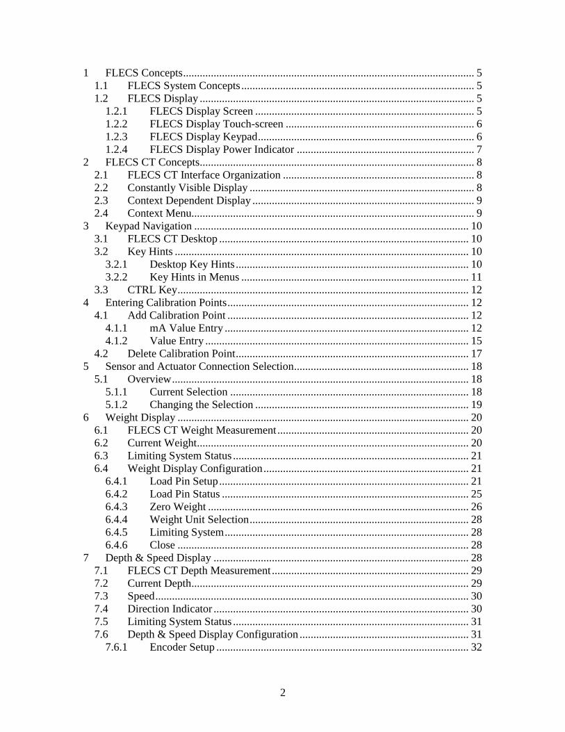
Figure 4 - FLECS Display with Keypad Highlighted
Most of the keys on the keypad have two functions. The primary function of the button is
the larger character printed in the center of the button. The secondary function of the
buttons is printed in smaller text on the lower right corner of the button.
Figure 5 – Key with Primary and Shifted Function Illustrated
The secondary function of the button is called the “shifted” function. The keypad has a
shift button labeled “SHIFT LOC”. When the shift function is enabled the red dot on the
lower right corner of the shift button will be illuminated. When shift is enabled pressing a
button will cause the secondary character to be entered. Pressing the shift button changes
the state of the shift.
1.2.4 FLECS Display Power Indicator
To the left of the screen is a red light which indicates power is being supplied to the
FLECS Display.

8
Figure 6 – Power Indicator, Illuminated
2 FLECS CT Concepts This section describes fundamental concepts of operating a FLECS CT system. These
concepts apply throughout the FLECS CT application.
2.1 FLECS CT Interface Organization
The interface for FLECS CT is divided into two primary sections. These two parts are
called the “constantly visible” and the “context dependent” sections.
2.2 Constantly Visible Display
The right one third of the screen is called the constantly visible section of the screen. This
part of the screen provides information that is critical for coiled tubing operations. This
information will always be visible on screen. Figure 7 highlights the constantly visible
section of the display.
The constantly visible section of the display is divided into three parts. The top third
provides information related to the tubing weight. The middle third provides information
related to the depth, speed and direction of tubing movement. The bottom third provides
the tubing and wellhead pressure.
Figure 7 – FLECS CT Display with Constantly Visible Display Highlighted

9
2.3 Context Dependent Display
The left two thirds of the screen is called the context dependent section of the screen.
Figure 8 highlights the context dependent section of the display. This part of the screen
provides information from additional sensors. This section of the screen is also used to
display menus for configuring the FLECS CT system.
The information from additional sensors is only displayed when all configuration menus
are closed. This part of the screen works similar to a Microsoft Windows desktop
computer. On a computer running Windows, when all applications (Word, Outlook, etc)
are closed you see the “desktop”. The “desktop” for FLECS CT displays information
from additional sensors. The information from these additional sensors is covered up
when a menu is opened for another reason.
Figure 8 – FLECS CT Display with Context Dependent Display Highlighted
2.4 Context Menu
In the FLECS CT application there are some operations which are infrequently
performed. Because of the limited space available on the FLECS screen, infrequently
used operations are hidden in what is called a context menu.
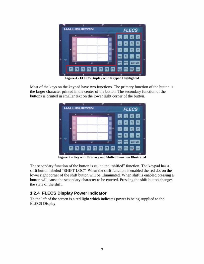
Throughout the FLECS CT application the context menu is accessed by pressing the
lower left most part of the touch screen or by pressing the F1 key. The area which opens
the context menu in FLECS CT is highlighted in Figure 9. This is called the context
menu button.
10
Figure 9 – FLECS CT with Context Menu Button Highlighted
When a context menu is open, a second press to the context menu button closes the
context menu.
When using a desktop computer running Microsoft Windows a right click on an object
causes a context menu to be displayed. For example if you right click on a folder in
Windows, a menu with options specific to that folder is displayed.
One can think of the context menu in FLECS CT like a right click in Windows. When
you press the context menu button in FLECS CT relevant options will be presented.
3 Keypad Navigation The FLECS CT software can be operated using either the touch screen or buttons on the
keypad. For hazardous area units keypad navigation is the only method of interacting
with the FLECS CT system. For safe area units the operator may use both the touch
screen and keypad navigation.
3.1 FLECS CT Desktop
The term “FLECS CT Desktop” refers to the state in which all menus are closed and the
six custom inputs are visible in the context dependent section of the screen. The custom
inputs are visible only when all other menus are closed. See Section 2.3 for more
information on the context dependent section of the screen.
3.2 Key Hints
FLECS CT uses key hints to show the operator what button on the keypad is the same as
touching an item on screen.
3.2.1 Desktop Key Hints
In Figure 10 the FLECS CT desktop is illustrated. In this illustration key hints are turned
on. The square with the four arrows and the word “Enter” in the top right is the currently
selected square. When an arrow key is pressed the selected square moves in the direction
of the arrow. Pressing the enter key has the same effect as touching in the selected square.

11
In the bottom right of Figure 10 there are two small squares. The upper square contains
the text “F7” and a symbol. The lower square contains the text “F8” and a symbol. These
tabs indicate that touching the extended touchable area buttons to the right of the tab will
have some effect. They also indicate that a press of the F7 key is the same as touching on
the touch screen in the extended touchable area. See Section 1.2.2.1 for more information
on the Extended Touchable Area.
While at the desktop as illustrated in Figure 10, if key hints are not enabled pressing an
arrow key or the enter key does not have any effect. However, the function keys F7 and
F8 are operational even if key hints are not displayed.
Desktop key hints are automatically hidden from view if no key is pressed for 15
seconds.
Figure 10 - Desktop Key Hint Label Illustration
3.2.2 Key Hints in Menus
When a menu is opened and key hints are enabled a hint appears over each part of the
screen which could be pressed with the touch screen. Pressing the key indicated by the
key hint is the same as touching on the item with the touch screen.
In Figure 11 the button labeled “Load Pin Setup” has a key hint in the top right
containing the text “F6”. This key hint indicates that pressing the F6 key is the same as
touching on the Load Pin Setup button.
Keypad navigation works for menus even if key hints are disabled. Key hints are always
numbered beginning with F2. Generally the items on screen are assigned keys left to
right, then top to bottom.

12
Figure 11 - Key Hint Label Illustration
3.3 CTRL Key
The CTRL key is used to enable and disable key hints. Each press of the CTRL key
changes the state of key hints. If key hints are off and CTRL is pressed key hints will be
turned on. If key hints are on and CTRL is pressed key hints will be turned off.
4 Entering Calibration Points The FLECS CT application uses a common process for adding calibration points for load
pins and the pressure transducers. The process of deleting existing calibration points is
also common.
Beginning in version 1.1 it is no longer possible to modify an existing calibration. The
incorrect calibration point must be deleted and then a new point added.
This section discusses the process of adding and deleting calibration points.
4.1 Add Calibration Point
After pressing the “Add Point” button from either the Load Pin Setup or transducer setup
screen, the Add Calibration Point mA screen is displayed. The first screen, illustrated in
Figure 12, prompts for the mA value of the calibration point.
4.1.1 mA Value Entry
Enter the mA value of the new calibration point in the text field. This field accepts
numeric values with up to two decimal places. The field will not allow numbers which
are out of the valid range indicated by the Range Bar.
After entering the mA value touch the Next button. The Next button will not be enabled
unless a valid value is entered in the mA field. To cancel the Add Calibration Point
process, touch the Cancel button.

13
Figure 12 – Add Calibration Point mA
4.1.1.1 mA Valid Range Bar
The center of the Add Calibration Point screen displays the valid range for a calibration
point mA value. This range is displayed by the green bar. This bar is called the Range
Bar. The Range Bar is surrounded by a blue oval in Figure 13.
Figure 13 – Add Calibration Point mA – Range Bar Detail – No Existing Points
4.1.1.1.1 Minimum mA Value
In Figure 13 the minimum mA value which can be entered is indicated below the left end
of the Range Bar. This value is enclosed in a red rectangle.
4.1.1.1.2 Maximum mA Value
In Figure 13 the maximum mA value which can be entered is indicated below the right
end of the Range Bar. This value is enclosed in a green triangle.
4.1.1.1.3 Existing Point Ranges

14
The mA value of any existing calibration points will be illustrated on the Range Bar with
an Existing Point Range. An Existing Point Range is illustrated with a red bar. The
Existing Point Range will be illustrated on top of the green Range Bar.
For some sensors a minimum spacing between the mA values of calibration points is
required. In this case the red Existing Point Range illustrates the range of mA values not
allowed because they are too close to an existing calibration point.
Figure 14 illustrates the Add Calibration Point mA screen with one existing point at 6.0
mA. The red Existing Point Range is detailed by a green triangle.
Figure 14 – Add Calibration Point mA – Existing Point
4.1.1.1.4 Entered Point Indicator
When a value is entered in the mA field a representation of that value is illustrated on the
Range Bar. This is called the Entered Point Indicator. The Entered Point Indicator is
illustrated with a tall, orange bar. The Entered Point Indicator bar moves each time a new
mA value is entered. In Figure 15 the Entered Point Indicator is highlighted with a blue
oval.

15
Figure 15 – Add Calibration Point mA – Entered Point Indicator
If a mA value is entered which overlaps the Existing Point Range of another calibration
point a message will be displayed under the mA field. The Next button will be disabled.
This situation is illustrated in Figure 16.
Figure 16 – Add Calibration Point mA– Invalid Point Entered
4.1.2 Value Entry
After confirming the mA value FLECS CT prompts for the value corresponding to the
entered mA value. For load pins the requested value will be a weight. For pressure
transducers the requested value will be a pressure. The display value is requested in the
selected units for the sensor.
After entering a value press the Finish button. Press cancel to exit the add calibration
point process without changing the sensor calibration.
The display value field will not allow entry of a value outside the valid range.
16
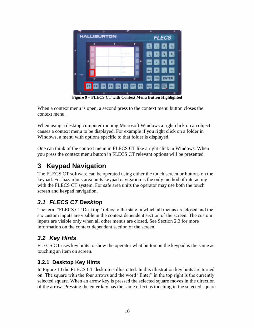
Figure 17 illustrates the screen used to enter the display value corresponding to the mA
value previously entered. In this example the calibration point is being added for a
pressure transducer.
Figure 17 – Add Calibration Point Value
4.1.2.1 Value Range Bar
The center of the Add Calibration Point screen displays the valid range for a calibration
point value. This range is displayed by the green bar. This bar is called the Display Value
Range Bar. The Display Value Range Bar is surrounded by a blue oval in Figure 18.
Figure 18 – Add Calibration Point Value
4.1.2.1.1 Minimum Display Value
In Figure 18 the minimum display value which can be entered is indicated below the left
end of the Range Bar. This value is enclosed in a red square.
4.1.2.1.2 Maximum Display Value
In Figure 18 the maximum display value which can be entered is indicated below the
right end of the Range Bar. This value is enclosed in a green triangle.

17
4.1.2.1.3 Existing Points
The valid range indicated by the range bar is calculated with respect to other existing
calibration points. The example in Figure 18 illustrates the display range bar for a
pressure transducer which had no existing calibration points. Because no other calibration
points existed the display value corresponding to the mA value could be anywhere
between 0 and 20,000 PSI.
4.1.2.1.4 Entered Point Indicator
When a value is entered in the display value field a representation of that value is
illustrated on the Range Bar. This is called the Entered Point Indicator. The Entered Point
Indicator is illustrated with a tall orange bar. The Entered Point Indicator bar moves each
time a new mA value is entered. In Figure 19 the Entered Point Indicator is highlighted
with a blue oval.
Figure 19 – Add Calibration Point Value – Entered Point Indicator
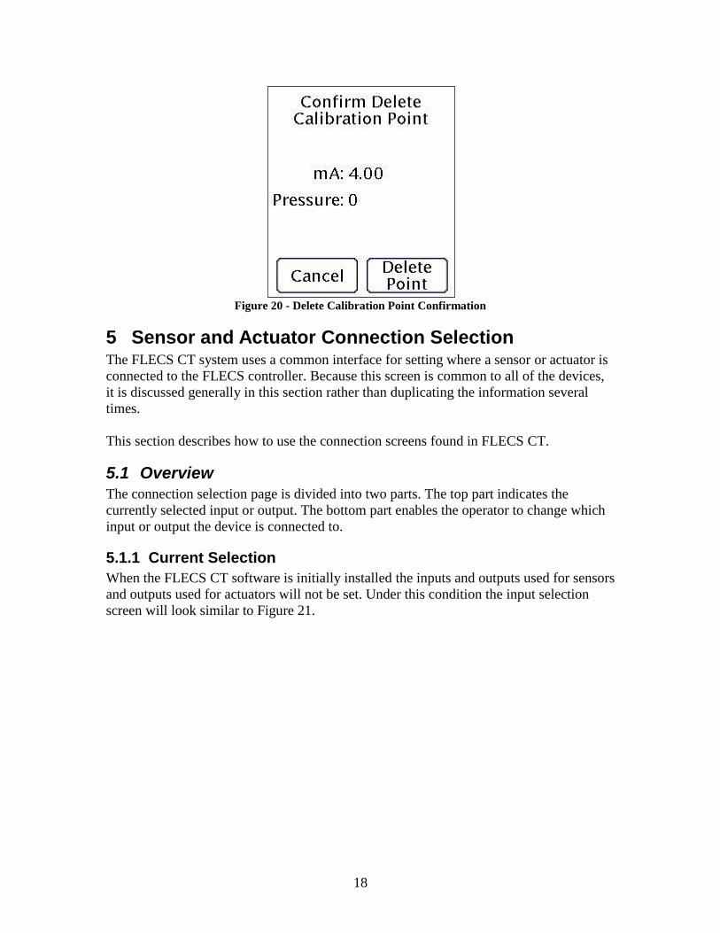
4.2 Delete Calibration Point
After touching on an existing calibration point the Delete Point button will be enabled.
Press the Delete Point button to delete the point. Press cancel to exit this screen without
modifying the sensor calibration.
18
Figure 20 - Delete Calibration Point Confirmation
5 Sensor and Actuator Connection Selection The FLECS CT system uses a common interface for setting where a sensor or actuator is
connected to the FLECS controller. Because this screen is common to all of the devices,
it is discussed generally in this section rather than duplicating the information several
times.
This section describes how to use the connection screens found in FLECS CT.
5.1 Overview
The connection selection page is divided into two parts. The top part indicates the
currently selected input or output. The bottom part enables the operator to change which
input or output the device is connected to.
5.1.1 Current Selection
When the FLECS CT software is initially installed the inputs and outputs used for sensors
and outputs used for actuators will not be set. Under this condition the input selection
screen will look similar to Figure 21.

19
Figure 21 - Connection Selection - Input Not Set
The top half of the display indicates that an input has not been assigned to the sensor yet.
Once an input has been selected the top half of the connection selection screen will show
which input is selected. This is illustrated in Figure 22.
Figure 22 - Connection Selection - Input Selected
5.1.2 Changing the Selection
To change which input or output is used use the arrow buttons to increase or decrease the
selection. The newly selected input or output is in the box between the two arrow buttons.
If the new selected input is already in use by this or another device, the apply button will
be disabled and the message “Analog Input Is In Use” will appear.
When the desired input is selected and it is available, press the apply button to make the
change effective. When the change is made, the top half of the screen will change to
show the newly selected input.

20
6 Weight Display The Weight display is the top one third of the Constantly Visible section of the screen.
The Weight display provides the current weight, the units the weight is displayed in and
the status of the load limiting system.
This section discusses general capabilities of the weight display system in FLECS CT
and describes the interface used for managing all aspects of the weight display.
Figure 23 – Weight Display
6.1 FLECS CT Weight Measurement
The FLECS CT system supports measurement of tubing weight using either one or two
load pins. Each configured load pin has an independent calibration table1. A load pin
calibration table must have at least two calibration points to be a valid calibration. A load
pin calibration table can consist of up to fifteen points.
When only one load pin is configured the force applied to the single load pin is doubled
to calculate the display weight. This is based on the assumption that exactly fifty percent
of the load is applied to the single installed pin.
When two load pins are configured the sum of the force applied to each pin is used for
the display weight.
6.2 Current Weight
The majority of the Weight display is used for display of the current tubing weight. In
Figure 24 the current weight has a red box around surrounding it. The weight is displayed
in the units selected on the Weight Display Configuration screen. The currently selected
unit has a blue oval around it in Figure 24.
Figure 24 – Weight Display, Current Weight & Units Highlighted
1 A calibration table relates the signal from a transducer to a display value. For example the most basic
calibration for a load pin might consist of two points: (4.00 mA, -17000 lbs) & (20.00 mA, 53000 lbs).

21
A value for the weight is displayed only if one or two load pins are configured and each
configured load pin has an input selected and a valid calibration table.
6.3 Limiting System Status
Just below the Current Weight display is the Load Limiting Status. The Load Limiting
status area is circled with a blue oval in Figure 25. The Load Limiting system is
discussed in Section 9 - Limiting System (Page 44).
Figure 25 – Weight Display – Load Limiting Status Highlighted
6.4 Weight Display Configuration
A touch in the Weight constantly visible area will open the Weight Display Configuration
menu. The Weight Display Configuration menu is displayed in the context dependent
section of the screen.
Figure 26 - Weight Display Configuration Menu
6.4.1 Load Pin Setup
The Load Pin Setup button opens the Load Pin Setup menu. From the Load Pin Setup
menu the number of pins to be used, the input each pin is connected to and the calibration
tables for each pin are configured.
6.4.1.1 No Pins Configured
When the FLECS CT software is initially installed or after all existing load pins are
deleted the load pin setup screen displays a message indicating no pins exist. Use the

22
context menu to add one or two load pins as appropriate. See Section 2.4 for more
information on the context menu.
Figure 27 - Load Pin Setup - No Pins Configured
6.4.1.2 Pin Selection
After one load pin has been added the load pin setup screen changes to look like that in
Figure 28. There is a single tab on the left side of the screen labeled “Pin 1”. Because
there is not a second side tab labeled “Pin 2” we know only one pin has been added to the
system.
All of the information in the Calibration and Input tabs applies to Pin 1.
Figure 28 - Load Pin Setup - Single Pin
When a second load pin has been added a second side tab appears. The new tab is labeled
“Pin 2”. The currently selected load pin has a white background. In Figure 29 Pin 1 is
selected. The information in the Calibration and Input tabs applies to Pin 1.

23
Figure 29 - Load Pin Setup - Two Pins - Pin 1 Selected
In Figure 30 Pin 2 is selected. The information in the Calibration and Input tabs applies to
Pin 2.
Figure 30 - Load Pin Setup - Two Pins - Pin 2 Selected
6.4.1.3 Add Load Pin
To add a pin to the system, select the Add Pin button from the Load Pin Setup context
menu.
When a pin is added the pin does not have an input selected and no calibration points
exist for the pin.
6.4.1.4 Input Tab
Use the input tab of the load pin setup screen to see the currently selected input and
change the selected input. See Section 5 for more information on how to use this screen.
The information on the input tab applies to the currently selected load pin.
24
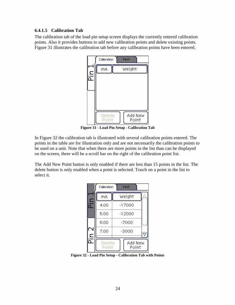
6.4.1.5 Calibration Tab
The calibration tab of the load pin setup screen displays the currently entered calibration
points. Also it provides buttons to add new calibration points and delete existing points.
Figure 31 illustrates the calibration tab before any calibration points have been entered.
Figure 31 - Load Pin Setup - Calibration Tab
In Figure 32 the calibration tab is illustrated with several calibration points entered. The
points in the table are for illustration only and are not necessarily the calibration points to
be used on a unit. Note that when there are more points in the list than can be displayed
on the screen, there will be a scroll bar on the right of the calibration point list.
The Add New Point button is only enabled if there are less than 15 points in the list. The
delete button is only enabled when a point is selected. Touch on a point in the list to
select it.
Figure 32 - Load Pin Setup - Calibration Tab with Points

25
6.4.1.6 Add Load Pin Calibration Point
Touch on the Add Point button to add a calibration point to the currently selected pin.
Refer to Section 4.1 - Add Calibration Point (Page 12) for instructions on adding
calibration points.
When 15 calibration points already exist the Add Point button will be disabled.
6.4.1.7 Delete Existing Calibration Point
To delete an existing calibration point, touch on the row of the calibration point to be
deleted in the calibration point list. This will select the point to be deleted. Press the
delete point button, read and acknowledge the confirmation screen.
6.4.1.8 Delete Load Pin
Select the pin to be deleted using the Pin Selection buttons on the left of the Load Pin
Setup menu. From the context menu press the Delete Pin button. Read and acknowledge
the confirmation screen.
When a pin is deleted from the system the calibration table is cleared, the input is made
available for use by other sensor setup menus and the pin is removed from the system.
Note: Once a pin has been deleted the information deleted with the pin cannot be
recovered.
6.4.2 Load Pin Status
The top section of the Weight Display Configuration menu provides the status of
configured load pins. There is a button for each pin which may be configured. These
buttons are called the pin status selection buttons. The pin status selection buttons are
labeled Pin 1 and Pin 2. Below the pin status selection buttons is an area where messages
related to the state of the selected pin will be displayed; this is referred to as the pin
status.
When no pins have been added to the system or all existing pins have been deleted both
buttons will be gray. The pin status below the buttons will read “NO PINS
CONFIGURED”.
After a pin has been added to the system one of the pin status selection buttons will
appear with black text. When two pins have been added to the system both buttons will
appear with black text.
The pin status information applies to the selected pin. If the input has not been selected
for the sensor the pin status will read “INPUT NOT CONFIGURED”. When the input
has been selected for a sensor the pin status area will display the signal currently being
received from the load pin.

26
Figure 33 illustrates the Load Pin Status area with no load pins configured. Note that
neither Pin 1 nor Pin 2 is selected and the text for each pin is grayed out. The text in the
pin status area reads “NO PINS CONFIGURED”.
Figure 33 – Load Pin Status, No Pins Configured
In Figure 34 one load pin has been added to the system but the no input has been
specified.
Figure 34 – Load Pin Status, One Pin Configured, Pin Input Not Configured
In Figure 35 one load pin has been added to the system and the input has been specified.
The signal being received from the pin is displayed.
Figure 35 – Load Pin Status, One Pin Configured, Pin Signal Displayed
Figure 36 illustrates the load pin status area with two pins configured and Pin 2 selected.
Figure 36 – Load Pin Status, Two Pins Configured, Pin Signal Displayed
6.4.3 Zero Weight
In the center of the Weight Display Configuration screen is a button labeled “Zero
Weight”. This button begins the process of applying an offset to the weight display. An
offset is used to hide forces associated with the system that are not applied to the tubing.
To zero the weight display, touch the Zero Weight button. After touching the Zero
Weight button a confirmation screen will be displayed. This screen displays information
regarding the action that will be taken on confirmation. Dependent upon the conditions of
the injector, reel and tubing this confirmation will display different messages. Always
carefully read the zero weight confirmation.
27
To confirm that the offset should be applied press the Confirm button from the context
menu. Alternately to cancel the Zero Weight process, press the Cancel button.
Figure 37 illustrates the Zero Weight Confirmation screen under normal conditions. The
weight to be offset was less than 2,000 pounds and the depth was not more than 50 feet.
Figure 37 – Zero Weight Confirmation - Normal
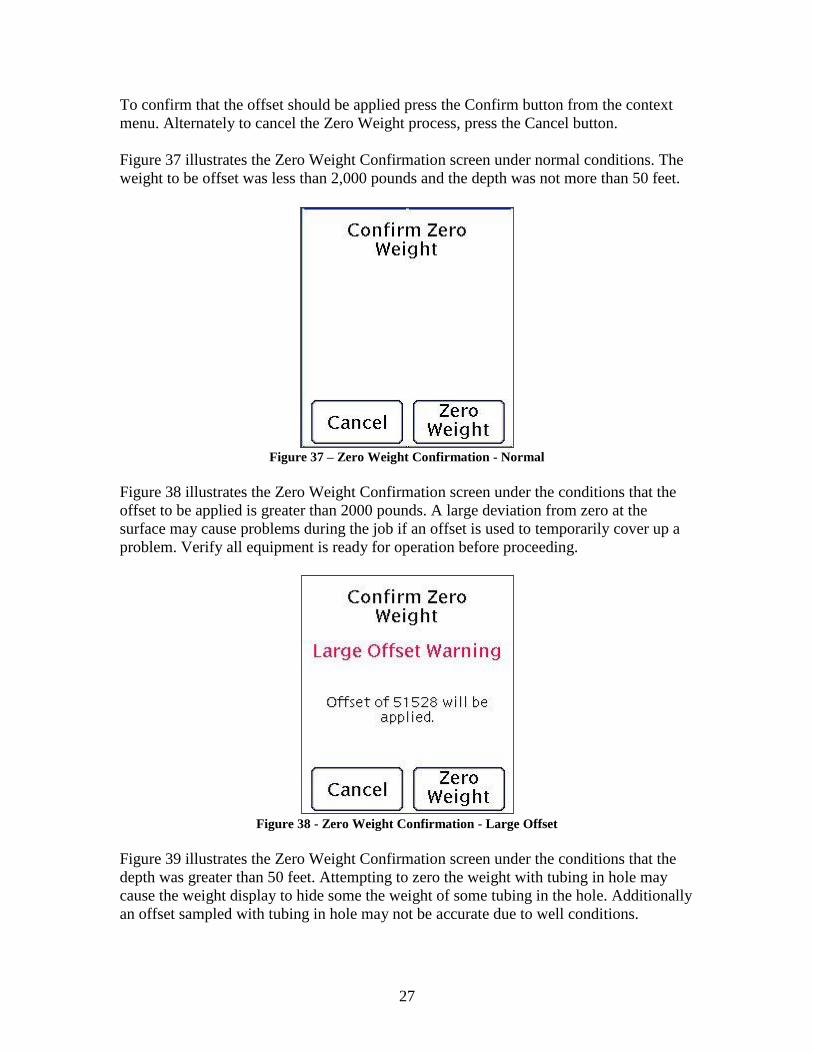
Figure 38 illustrates the Zero Weight Confirmation screen under the conditions that the
offset to be applied is greater than 2000 pounds. A large deviation from zero at the
surface may cause problems during the job if an offset is used to temporarily cover up a
problem. Verify all equipment is ready for operation before proceeding.
Figure 38 - Zero Weight Confirmation - Large Offset
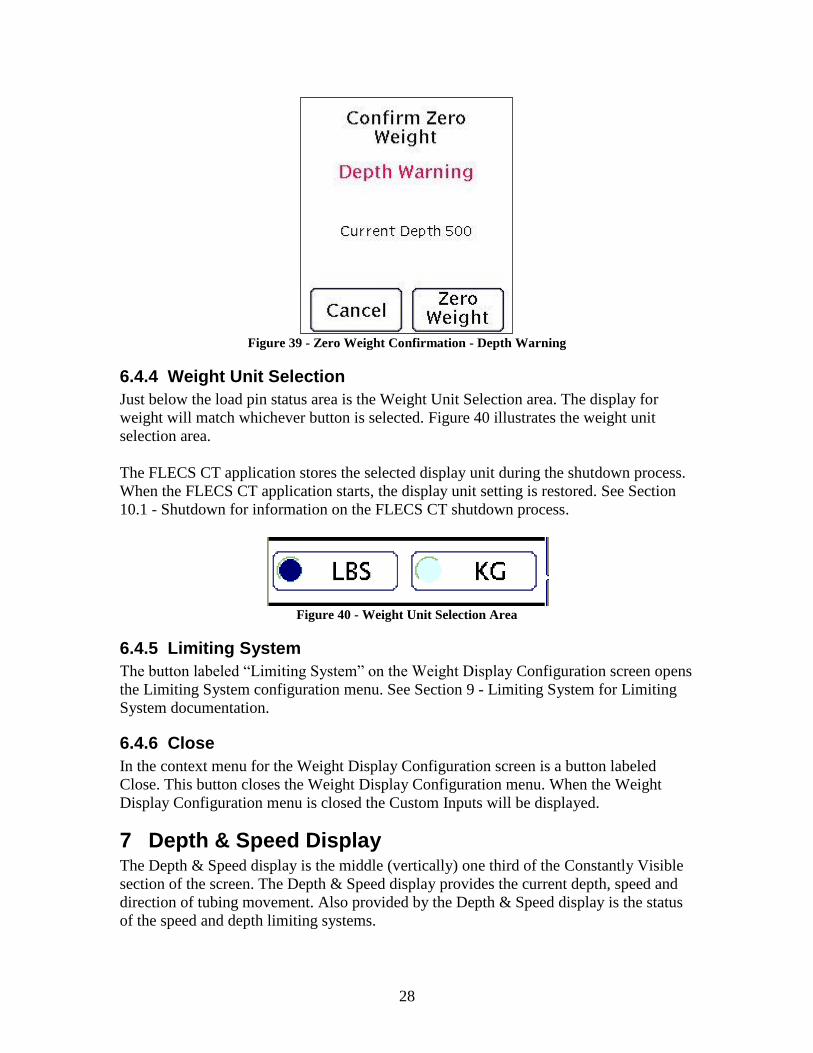
Figure 39 illustrates the Zero Weight Confirmation screen under the conditions that the
depth was greater than 50 feet. Attempting to zero the weight with tubing in hole may
cause the weight display to hide some the weight of some tubing in the hole. Additionally
an offset sampled with tubing in hole may not be accurate due to well conditions.
28
Figure 39 - Zero Weight Confirmation - Depth Warning
6.4.4 Weight Unit Selection
Just below the load pin status area is the Weight Unit Selection area. The display for
weight will match whichever button is selected. Figure 40 illustrates the weight unit
selection area.
The FLECS CT application stores the selected display unit during the shutdown process.
When the FLECS CT application starts, the display unit setting is restored. See Section
10.1 - Shutdown for information on the FLECS CT shutdown process.
Figure 40 - Weight Unit Selection Area
6.4.5 Limiting System
The button labeled “Limiting System” on the Weight Display Configuration screen opens
the Limiting System configuration menu. See Section 9 - Limiting System for Limiting
System documentation.
6.4.6 Close
In the context menu for the Weight Display Configuration screen is a button labeled
Close. This button closes the Weight Display Configuration menu. When the Weight
Display Configuration menu is closed the Custom Inputs will be displayed.
7 Depth & Speed Display The Depth & Speed display is the middle (vertically) one third of the Constantly Visible
section of the screen. The Depth & Speed display provides the current depth, speed and
direction of tubing movement. Also provided by the Depth & Speed display is the status
of the speed and depth limiting systems.

29
This section discusses general capabilities of the Depth & Speed display system in
FLECS CT and describes the interface used for managing all aspects of the Depth &
Speed display.
Figure 41 – Depth & Speed Display
7.1 FLECS CT Depth Measurement
The FLECS CT system measures depth using an encoder. The encoder is connected to a
wheel which contacts the tubing. The FLECS CT system is capable of using encoders of
different resolutions and wheels of different circumferences.
The Halliburton standard encoder has a resolution of 500 pulses per revolution. The
Halliburton standard wheel has a circumference of 2.000 feet.
7.2 Current Depth
The large number in the top half of the Depth & Speed display indicates the current
depth. Depth increases as the direction of tubing movement is in hole. The depth will
become negative when tubing moves above the point at which the depth was set to zero.
The unit the depth is currently displayed in is indicated in the above and right of the
current depth.
The depth is not displayed if the encoder does not have a valid calibration.
In Figure 42 the current depth is circled by a blue oval. The current units indicator is
enclosed in a green triangle.
Figure 42 – Depth & Speed Display – Depth & Units Highlighted
30
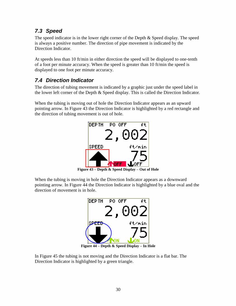
7.3 Speed
The speed indicator is in the lower right corner of the Depth & Speed display. The speed
is always a positive number. The direction of pipe movement is indicated by the
Direction Indicator.
At speeds less than 10 ft/min in either direction the speed will be displayed to one-tenth
of a foot per minute accuracy. When the speed is greater than 10 ft/min the speed is
displayed to one foot per minute accuracy.
7.4 Direction Indicator
The direction of tubing movement is indicated by a graphic just under the speed label in
the lower left corner of the Depth & Speed display. This is called the Direction Indicator.
When the tubing is moving out of hole the Direction Indicator appears as an upward
pointing arrow. In Figure 43 the Direction Indicator is highlighted by a red rectangle and
the direction of tubing movement is out of hole.
Figure 43 – Depth & Speed Display – Out of Hole
When the tubing is moving in hole the Direction Indicator appears as a downward
pointing arrow. In Figure 44 the Direction Indicator is highlighted by a blue oval and the
direction of movement is in hole.
Figure 44 – Depth & Speed Display – In Hole
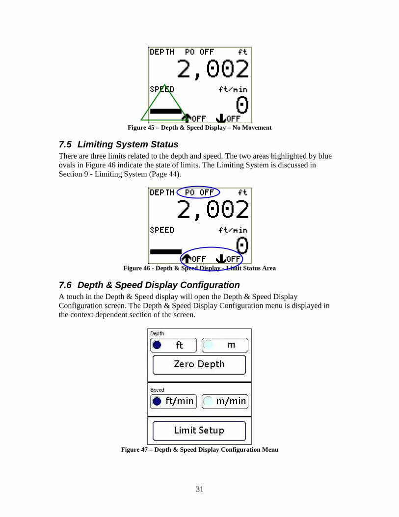
In Figure 45 the tubing is not moving and the Direction Indicator is a flat bar. The
Direction Indicator is highlighted by a green triangle.
31
Figure 45 – Depth & Speed Display – No Movement
7.5 Limiting System Status
There are three limits related to the depth and speed. The two areas highlighted by blue
ovals in Figure 46 indicate the state of limits. The Limiting System is discussed in
Section 9 - Limiting System (Page 44).
Figure 46 - Depth & Speed Display - Limit Status Area
7.6 Depth & Speed Display Configuration
A touch in the Depth & Speed display will open the Depth & Speed Display
Configuration screen. The Depth & Speed Display Configuration menu is displayed in
the context dependent section of the screen.
Figure 47 – Depth & Speed Display Configuration Menu

32
7.6.1 Encoder Setup
Located in the context menu of the Depth & Speed Display Configuration menu is a
button labeled “Encoder Setup”. The Encoder setup button is used to configure which
input the Encoder is connected to, set the resolution of the encoder and set the wheel
circumference.
7.6.1.1 Input Tab
The input tab is used to specify where the encoder is connected to the FLECS controller.
See Section 5 for details on this screen.
Note that FLECS frequency inputs not configured as Quadrature type will show as “In
Use” on this screen.
Figure 48 - Encoder Setup - Input Tab
7.6.1.2 Calibration Tab
The calibration tab is used to apply a calibration for the encoder. This calibration is used
to calculate depth and speed.
When the FLECS CT software is initially installed there will not be a calibration for the
encoder. The calibration tab will appear with message indicating the calibration is not yet
set. To set a new calibration or modify an existing calibration press the “Set/Modify
Calibration” button.
Once a calibration has been set, the calibration tab will appear as illustrated in Figure 49.

33
Figure 49 – Encoder Setup – Calibration Tab
7.6.2 Depth Unit Selection
Near the top of the Depth & Speed Display Configuration menu are two buttons labeled
“ft” and “m”. These two buttons are used to select the units for display of the depth. The
currently selected unit is illustrated with a darkened circle on the left side of the button.
The abbreviation “ft” represents feet. The abbreviation “m” represents meters.
The FLECS CT application stores the selected display unit during the shutdown process.
When the FLECS CT application starts, the display unit setting is restored. See Section
10.1 - Shutdown for information on the FLECS CT shutdown process.
In Figure 50 the Depth Unit Selection buttons are enclosed in a red rectangle. The
currently selected unit is “ft”.
Figure 50 – Depth & Speed Configuration – Depth Unit Buttons Highlighted

34
7.6.3 Speed Unit Selection
Near the center of the Depth & Speed Display Configuration menu are two buttons
labeled “ft/min” and “m/min”. These two buttons are used to select the units for display
of the speed. The currently selected unit is illustrated with a darkened circle on the left
side of the button.
The abbreviation “ft/min” represents feet per minute. The abbreviation “m/min”
represents meters per minute.
The FLECS CT application stores the selected display unit during the shutdown process.
When the FLECS CT application starts, the display unit setting is restored. See Section
10.1 - Shutdown for information on the FLECS CT shutdown process.
In Figure 51 the Speed Unit Selection buttons are enclosed in a blue oval. The currently
selected unit is “ft/min”.
Figure 51 – Depth & Speed Configuration – Speed Unit Buttons Highlighted
7.6.4 Zero Depth
Just below the Depth Unit Selection buttons is a button labeled “Zero Depth”. This button
is used to set the current depth to zero. In Figure 52 the Zero Depth button is enclosed in
a red rectangle.
To set the depth display to zero, press the Zero Depth button. A confirmation screen will
be displayed indicating what action will be taken upon confirmation. To proceed and set
the depth to zero press the confirm button. To cancel the zero depth process, press the
cancel button.

35
Figure 52 – Depth & Speed Configuration – Zero Depth
When the tubing is in motion the Zero Depth button will be disabled. This is a safety
feature related to the load limiting system. When the Zero Depth button is disabled the
text in the center of the button appears in a light gray color and pressing the button has no
effect.
7.6.5 Set Depth
The Set Depth feature is used to set the current depth display to a value specified by the
operator. In the context menu of the Depth & Speed Display Configuration screen is a
button labeled “Set Depth”. In Figure 53 the Set Depth button is highlighted by a blue
oval.
Figure 53 – Depth & Speed Configuration Context Menu – Set Depth
To set the depth display to a new value press the Set Depth button. The Set Current Depth
screen will be displayed. The Set Current Depth display is illustrated in Figure 54.
The Set Current Depth screen has a field in the center for entering a new depth. In Figure
54 the New Depth field is enclosed in a red rectangle. The depth is entered in the

36
currently selected units for depth display. The selected unit is indicated to the right of the
New Depth field.
Enter the new depth for the depth display then press the apply button. The apply button is
disabled until a valid value is entered in the New Depth field.
Figure 54 – Set Current Depth
After pressing the apply button a confirmation screen will be displayed indicating the
action that will take place upon confirmation. Read the information on this screen. To
implement the change touch on the Confirm. To cancel the set depth operation press the
cancel button.
When the tubing is in motion the Set Depth button will be disabled. This is a safety
feature related to the load limiting system. When the Set Depth button is disabled the text
in the center of the button appears in a light gray color and pressing the button has no
effect.
7.6.6 Limiting System
The button labeled “Limiting System” at the bottom of the Depth & Speed Display
Configuration screen opens the Limiting System configuration menu. See Section 9 -
Limiting System (Page 44) for Limiting System documentation.
7.6.7 Close
In the context menu for the Depth & Speed Display Configuration screen is a button
labeled Close. This button closes the Depth & Speed Display Configuration menu. When
the Depth & Speed Display Configuration menu is closed the Custom Inputs will be
displayed.
8 Pressure Display The pressure display is the bottom one third of the constantly visible section of the
screen. The pressure display provides the tubing and wellhead pressures. In Figure 55 the
pressure display is highlighted in a red rectangle.

37
This section discusses the general capabilities of the pressure display and describes the
interface used for managing all aspects of the pressure display.
Figure 55 – Pressure Display
8.1 FLECS CT Pressure Measurement
The FLECS CT system measures pressure using pressure transducers. The standard
pressure transducer is a 0 – 15,000 PSI transducer with a 4-20 mA output. The FLECS
CT system is capable of using analog output pressure transducers with other pressure
ranges, up to 20,000 PSI.
8.2 Tubing Pressure
The top half of the pressure display provides the tubing pressure. The current pressure is
displayed in large black text in the top half of the pressure display. The selected unit for
the tubing pressure is displayed above the tubing pressure on the right side of the pressure
display.
In Figure 56 the tubing pressure is enclosed in a blue oval. The selected unit is
highlighted by a green triangle.

38
Figure 56 – Pressure Display – Tubing Pressure
8.3 Wellhead Pressure
The bottom half of the pressure display provides the wellhead pressure. The current
pressure is displayed in large black text in the bottom half of the pressure display. The
selected unit for the wellhead pressure is displayed above the wellhead pressure on the
right side of the pressure display.
In Figure 57 the wellhead pressure is enclosed in a red rectangle. The selected unit is
highlighted by a blue oval.
Figure 57 – Pressure Display – Wellhead Pressure
8.4 Pressure Display Configuration
A touch in the pressure display opens the Pressure Display Configuration menu. The
Pressure Display Configuration screen is displayed in the context dependent section of
the screen. Figure 58 illustrates the Pressure Display Configuration menu.
Configuration of the tubing and wellhead pressure transducers use similar screens. Only
configuration of the tubing pressure transducer is illustrated in this document.

39
Figure 58 – Pressure Display Configuration
8.4.1 Tubing Pressure Transducer Status
Just below the Tubing Pressure text at the top of the screen the tubing pressure transducer
status is displayed. In Figure 59 the Tubing Status area is circled by a blue oval.
Figure 59 – Pressure Display Configuration – Tubing Status
If the input has not been selected for the tubing transducer the status area will display
“Input Not Configured”.
8.4.2 Tubing Pressure Display Unit
In the top left quarter of the Pressure Display Configuration menu are three buttons
labeled “PSI”, “kPa” and “MPa”. These three buttons are surrounded by a red rectangle
in Figure 60.
A touch on one of these three buttons changes the units for the tubing pressure value.

40
Figure 60 – Pressure Display Configuration – Tubing Display Unit
8.4.3 Tubing Pressure Zero
In the top right of the Pressure Display Configuration menu is a large button labeled
“Zero”. This button is used to apply an offset to the tubing pressure. The zero button is
highlighted by a green triangle in Figure 61.
Figure 61 – Pressure Display Configuration – Zero
Before performing the zero process for a pressure transducer ensure that the transducer is
exposed to atmospheric pressure. Touch on the zero button to begin the zero process. The
Confirm Zero Transducer screen will be displayed indicating what action is going to take
place upon confirmation. The Confirm Zero Transducer screen is illustrated in Figure 62.
Read the message carefully. To confirm and execute the zero process, press Zero
Pressure. To cancel press the Cancel button.

41
Figure 62 – Confirm Zero Pressure
A safety feature is integrated into FLECS CT which prevents the pressure display from
differing from the actual pressure on the transducer because of a large offset. This
condition could occur if the transducer was exposed to pressure when a zero process was
executed. This feature also prevents the zero process from being executed if the
transducer signal is below the reasonable operating range for the transducer.
When the signal from a pressure transducer is more than 4.50 mA the Cannot Zero
Transducer message will be displayed. The only option is to touch Cancel and correct the
condition causing the high transducer signal. Figure 63 illustrates the message displayed
under these conditions.
Figure 63 – Cannot Zero Pressure – High Signal
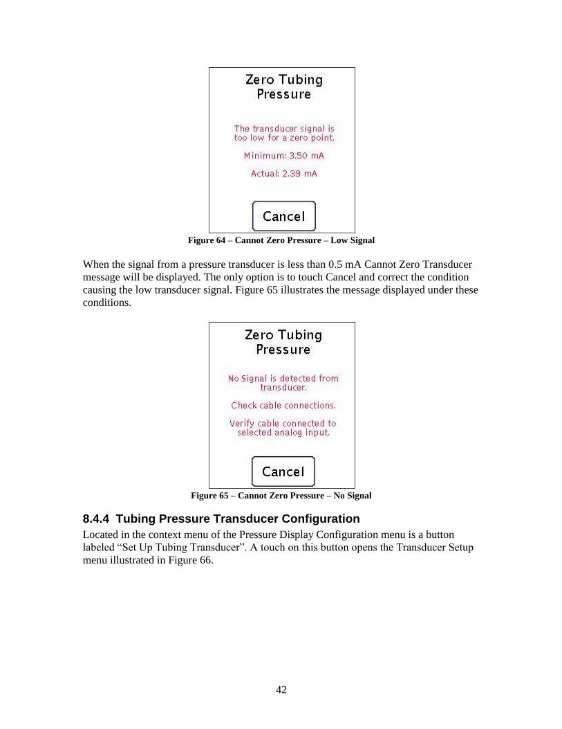
When the signal from a pressure transducer is less than 3.5 mA but greater than 0.5 mA
the Cannot Zero Transducer message will be displayed. The only option is to touch
Cancel and correct the condition causing the low transducer signal. Figure 64 illustrates
the message displayed under these conditions.
42
Figure 64 – Cannot Zero Pressure – Low Signal
When the signal from a pressure transducer is less than 0.5 mA Cannot Zero Transducer
message will be displayed. The only option is to touch Cancel and correct the condition
causing the low transducer signal. Figure 65 illustrates the message displayed under these
conditions.
Figure 65 – Cannot Zero Pressure – No Signal
8.4.4 Tubing Pressure Transducer Configuration
Located in the context menu of the Pressure Display Configuration menu is a button
labeled “Set Up Tubing Transducer”. A touch on this button opens the Transducer Setup
menu illustrated in Figure 66.

43
Figure 66 – Tubing Pressure Setup – Calibration Tab
8.4.4.1 Input Selection Tab
Use the input tab to see the currently selected input and change the selected input. See
Section 5 for more information on how to use this screen.
8.4.4.2 Point List
A table providing the list of currently configured calibration points is illustrated on the
Transducer Setup screen. Figure 67 shows the Load Pin Setup menu with a red box
around the Calibration Point List. Two calibration points exist in Figure 67.
Figure 67 – Transducer Setup - Calibration Point List
Note: A pressure transducer must have two calibration points for a valid configuration.
8.4.4.3 Add Calibration Point
At the bottom of the Transducer Setup menu is a button labeled “Add Point”. The Add
Point button is illustrated with a blue oval in Figure 68. In the illustration the button is

44
disabled. A pressure transducer has a maximum of two calibration points. If two points
have already been added the button will be disabled.
Figure 68 – Transducer Setup – Add Point Button
Touch on the Add Point button to add a calibration point. Refer to Section 4.1 - Add
Calibration Point (Page 12) for instructions on adding calibration points for sensors with
current outputs.
8.4.4.4 Delete Existing Calibration Point
To delete an existing calibration point, touch on the row of the calibration point to be
deleted in the calibration point list. Press the delete point button then read and confirm
the point should be deleted.
8.4.5 Close
In the context menu for the Pressure Display Configuration screen is a button labeled
Close. This button closes the Pressure Display Configuration menu. When the menu is
closed the Custom Inputs will be displayed.
9 Limiting System The Limiting System monitors several aspects of the coiled tubing unit. When conditions
exceed a predefined threshold the CT unit is stopped.
The Limiting System consists of three components. The first component is the set of
sensors used to measure the state of the CT unit. The load pin(s) are used to measure the
state of the forces applied to the tubing. The encoder is used to measure the depth, speed
and direction of the tubing.
The second component of the Limiting System is the FLECS controller. The FLECS
controller observes the state of the system using the sensors described above. Ten times
per second the FLECS controller evaluates each limit to determine if the state of the CT
unit is still within the limits established by the operator.

45
If the FLECS controller determines the CT unit has exceeded the limits the third
component of the Limiting System is used to stop the injector. A pair of electrically
controlled valves simultaneously stop the injector and set the injector brake.
The Limiting System is designed to quickly react to an emergency situation. The
Limiting System is not designed to reduce operator workload. The injector experiences
high loads when rapidly stopping the motion of tubing. Configuration of the Limiting
System resulting in frequently exceeded limits will reduce the lifespan of some
components of the injector.
The Limiting System consists of six individual limits. The operation of each individual
limit is described in Sections 9.2 and 9.3.
9.1 Limit States
The way the FLECS CT controller conveys information about each limit is by displaying
the state of the limit. Each of the limits moves between one of the five states as a result of
actions taken by the operator and signals received by sensors.
The remainder of this section describes what each of the five states means and how the
state is illustrated on the FLECS display. Also discussed are the actions the FLECS CT
controller takes when a limit is in the state.
The information in this section is generalized. For details specific to each limit see the
section discussing the relevant limit.
The state of each limit is illustrated in the constantly visible display related to the limit. In
each section describing a limit state an illustration of each limit in the described state is
provided.
9.1.1 Off
The Off state indicates the operator has turned the limit off. While off the limit state will
be illustrated with black text on a red background. The text for the limit will contain the
word “Off”.
The FLECS CT application does not evaluate the limit when in the off state. The FLECS
controller will not automatically turn a limit on under any conditions. Limits must be
turned on by the operator.

46
Figure 69 – All Limits Off
9.1.2 On
The On state will be illustrated with green text on a white background. The text for the
limit state will contain the word “On”.
The FLECS CT application monitors the sensors associated with the limit. The signal
from the sensor indicates that the limit is within the currently established threshold.
Figure 70 – All Limits On

47
9.1.3 Warn
The Warn state will be illustrated with black text on a yellow background. The yellow
background will fill the entire constantly visible display associated with the limit. The
text for the limit state will contain the word “Warn”.
The FLECS CT application monitors the sensors associated with the limit. The FLECS
CT application has determined that the limit is close to the established threshold. Action
should be taken to prevent the limit from tripping.
Not all limits will enter the warning state before enter the tripped state. If the conditions
of the CT unit are changing rapidly even limits with a warning state may move directly
from On to Tripped without warning.
Figure 71 – Warn State
9.1.4 System Disabled
The System Disabled state is illustrated with black text on a white background. The text
for the limit state will contain the word “Off”.
The FLECS CT application monitors the sensors associated with the limit. The FLECS
CT application has determined that a rapid shutdown of the injector would be unsafe
under current conditions. The limit will not trip even if the threshold for the limit is
exceeded.
All limits will exit System Disabled state regardless of the speed if the depth is less than
100 feet.
If the limit is turned on the limit will be restored to On or Warn state when system
conditions indicate that a rapid shutdown of the injector is safe. If the FLECS CT

48
application determines that the potential consequences of a rapid shutdown of the injector
are less serious than not taking this action the FLECS CT application will restore the
limits to the On or Warn state.
All limits which are on when a limit system test begins will be set to System Disabled
state until the test is ended.
Figure 72 – System Disabled State
9.1.5 Tripped
The Tripped state is illustrated with black text on a red background. The red background
will fill the entire constantly visible display associated with the limit. The text for the
limit state will contain the word “Limit”.
The FLECS CT application determined that the threshold for the limit has been exceeded.
The FLECS CT application uses the limiting system valves to dump injector pressure and
set the injector brake.
See Section 9.5 - Resetting Tripped Limits (Page 61) for details on resetting tripped
limits.

49
Figure 73 – Tripped State
9.2 Weight Limits
There are three limits related to the weight. This section provides details on the operation
of each limit.
Each of the Weight Limits requires all components of the Load Limiting system to be
operating correctly to be effective.
9.2.1 Pull Limit
The Pull Limit compares the current weight to a threshold set by the operator. When the
weight is within 1500 pounds of the threshold the limit will enter Warn state. When the
weight exceeds the threshold the limit will enter Tripped state.
The Pull Limit will enter System Disabled state if the out of hole speed exceeds 50 feet
per minute. When the out of hole speed drops below 50 feet per minute the Pull Limit
will exit System Disabled State. When the depth is less than 100 feet the Pull Limit will
exit System Disabled State regardless of tubing speed.
FLECS CT will not allow the Pull Limit to be enabled if the load pin configuration is
invalid or if the primary encoder has not been configured. See Section 6.4.1 - Load Pin
Setup (Page 21) for more information on configuring load pins. See Section 7.6.1 -
Encoder Setup (Page 32) for more information on the primary encoder setup.
All calculations related to the Pull Limit are performed in pounds regardless of the
display unit.

50
The FLECS CT application does not evaluate the limit when in the off state. The FLECS
controller will not automatically turn a limit on under any conditions. Limits must be
turned on by the operator.
9.2.2 Snub Limit
The Snub Limit compares the current weight to a threshold set by the operator. When the
weight is within 1500 pounds of the threshold the limit will enter Warn state. When the
weight exceeds the threshold the limit will enter Tripped state.
The Snub Limit will enter System Disabled state if the out of hole speed exceeds 50 feet
per minute. When the out of hole speed drops below 50 feet per minute the Snub Limit
will enter the relevant state based on the comparison of current weight to Snub Limit
threshold. When the depth is less than 100 feet the Snub Limit will exit System Disabled
State regardless of tubing speed.
FLECS CT will not allow the Snub Limit to be enabled if the load pin configuration is
invalid or if the primary encoder has not been configured. See Section 6.4.1 - Load Pin
Setup (Page 21) for more information on configuring load pins. See Section 7.6.1 -
Encoder Setup (Page 32) for more information on the primary encoder setup.
All calculations related to the Snub Limit are performed in pounds regardless of the
display unit.
The FLECS CT application does not evaluate the limit when in the off state. The FLECS
controller will not automatically turn a limit on under any conditions. Limits must be
turned on by the operator.
9.2.3 Tag Limit
The Tag Limit monitors the rate of change of the current weight. If the weight changes by
more than 800 pounds in one tenth of a second the Tag Limit enters the Tripped state.
There is no Warn state for the tag limit.
The Tag Limit will enter System Disabled state if the out of hole speed exceeds 50 feet
per minute. When the out of hole speed drops below 50 feet per minute the Tag Limit
will enter the relevant state based on the comparison of current weight to Tag Limit
threshold. When the depth is less than 100 feet the Tag Limit will exit System Disabled
State regardless of tubing speed.
FLECS CT will not allow the Tag Limit to be enabled if the load pin configuration is
invalid or if the primary encoder has not been configured. See Section 6.4.1 - Load Pin
Setup (Page 21) for more information on configuring load pins. See Section 7.6.1 -
Encoder Setup (Page 32) for more information on the primary encoder setup.
All calculations related to the Tag Limit are performed in pounds regardless of the
display unit.

51
The FLECS CT application does not evaluate the limit when in the off state. The FLECS
controller will not automatically turn a limit on under any conditions. Limits must be
turned on by the operator.
9.3 Depth & Speed Limits
There are three limits related to the depth and speed. This section provides details on the
operation of each limit.
Each of the Depth & Speed Limits requires all components of the Load Limiting system
to be operating correctly to be effective.
9.3.1 Pull Out Limit
The Pull Out Limit monitors the current depth and speed. The Pull Out limit will enter
System Disabled state when the direction is out of hole and the speed exceeds 50 feet per
minute.
The Pull Out Limit exits System Disabled state regardless of speed when the depth is less
than 100 ft.
The Pull Out Limit enters the Warn state under two conditions. The Warn state will be
entered when the time to zero depth is less than sixty seconds and the direction is out of
hole. The Warn state will also be entered when the depth is 25 feet or less and the
direction is out of hole, regardless of the speed.
The Pull Out Limit enters the Tripped state under two conditions. The Tripped state will
be entered when the time to zero depth is less than 10 seconds and the direction is out of
hole. The Tripped state will also be entered when the depth is 10 feet or less and the
direction is out of hole, regardless of the speed.
FLECS CT will not allow the Pull Out Limit to be enabled if the load pin configuration is
invalid or if the primary encoder has not been configured. See Section 6.4.1 - Load Pin
Setup (Page 21) for more information on configuring load pins. See Section 7.6.1 -
Encoder Setup (Page 32) for more information on the primary encoder setup.
The FLECS CT application does not evaluate the limit when in the off state. The FLECS
controller will not automatically turn a limit on under any conditions. Limits must be
turned on by the operator.
FLECS CT will not allow the Pull Out Limit to be enabled if the load pin configuration is
invalid or if the primary encoder has not been configured. See Section 6.4.1 - Load Pin
Setup (Page 21) for more information on configuring load pins. See Section 7.6.1 -
Encoder Setup (Page 32) for more information on the primary encoder setup.
9.3.2 Speed Out of Hole Limit
The Speed Out of Hole limit compares the current speed to a threshold set by the
operator. When the direction is out of hole and the speed is within 15 feet per minute of

52
the threshold the limit will enter Warn state. When the direction is out of hole and the
speed exceeds the threshold the limit will enter Tripped state.
The Speed Out of Hole Limit will enter System Disabled state if the out of hole speed
exceeds 50 feet per minute. When the out of hole speed drops below 50 feet per minute
the limit will enter the relevant state based on the comparison of current speed to limit
threshold. When the depth is less than 100 feet the Speed Out of Hole Limit will exit
System Disabled State regardless of tubing speed.
FLECS CT will not allow the limit to be enabled if the load pin configuration is invalid
or if the primary encoder has not been configured. See Section 6.4.1 - Load Pin Setup
(Page 21) for more information on configuring load pins. See Section 7.6.1 - Encoder
Setup (Page 32) for more information on the primary encoder setup.
All calculations related to the Speed Out of Hole Limit are performed in feet per minute
regardless of the display unit.
The FLECS CT application does not evaluate the limit when in the off state. The FLECS
controller will not automatically turn a limit on under any conditions. Limits must be
turned on by the operator.
9.3.3 Speed In Hole Limit
The Speed In Hole limit compares the current speed to a threshold set by the operator.
When the direction is in hole and the speed is within 15 feet per minute of the threshold
the limit will enter Warn state. When the direction is in hole and the speed exceeds the
threshold the limit will enter Tripped state.
The Speed In Hole Limit will enter System Disabled state if the out of hole speed exceeds
50 feet per minute. When the out of hole speed drops below 50 feet per minute the limit
will enter the relevant state based on the comparison of current speed to limit threshold.
When the depth is less than 100 feet the Speed In Hole Limit will exit System Disabled
State regardless of tubing speed.
FLECS CT will not allow the limit to be enabled if the load pin configuration is invalid
or if the primary encoder has not been configured. See Section 6.4.1 - Load Pin Setup
(Page 21) for more information on configuring load pins. See Section 7.6.1 - Encoder
Setup (Page 32) for more information on the primary encoder setup.
All calculations related to the Speed In Hole Limit are performed in feet per minute
regardless of the display unit.
The FLECS CT application does not evaluate the limit when in the off state. The FLECS
controller will not automatically turn a limit on under any conditions. Limits must be
turned on by the operator.

53
9.4 Limit Setup
The Limit Setup menus can be accessed with two different methods. Both the Weight
Display Configuration and Depth & Speed Display Configuration menus have a Limiting
Setup button. See Sections 6.4.5 (Page 28) and 7.6.6 (Page 36) for more information on
accessing the Limit Setup screen.
There are four sections in Limit Setup menu. The sections of the Limit Configuration
menu are referred to as “tabs.” Each tab of the Limit Setup menu provides options for
configuration a specific part of the Limiting System.
Figure 74 illustrates the tabs with Output tab currently selected. The currently selected
tab has a white background. The other two tabs are illustrated with a gray background.
To change to another tab touch the desired tab. Not all tabs are visible on the screen. Use
the left and right arrow buttons to scroll through the available tabs.
FLECS CT will not allow changing from the output tab until the digital output has been
configured.
Figure 74 – Limiting System Tabs
9.4.1 Output Tab
The Output Tab is used to select the digital output controlling the two load limiting
valves. When FLECS CT is installed there is not a digital output selected. Until a digital
output is selected no other tabs are accessible. Figure 75 illustrates the Output tab. In
Figure 75 the output has not yet been configured.

54
Figure 75 – Limiting System Configuration – Output Configuration
9.4.1.1 Output Selection
See Section 5 (Page 18) for details on using the output selection screen.
9.4.2 Weight Tab
The Weight Tab is used to enable or disable the Pull, Snub and Tag limits and to set the
thresholds for the Pull and Snub limits. The Weight tab is divided into three sections, one
for each of the limits. The labels on the left side of the screen indicate which limit the
information displayed in the section applies to. Figure 76 illustrates the Weight tab.
Notice the three blue squares to the right of each limit name. Each of these is called a
checkbox. A checkbox is much like an on off switch. When a limit is turned on a check
mark will appear in the middle of each box. In Figure 76 the Snub Limit is on because
there is a check mark in the box. When a limit is off there is no check mark in the
checkbox. In Figure 76 the Pull Limit is off. To change the state of a check box touch on
the checkbox.
Figure 76 – Limiting System Configuration - Weight Tab

55
9.4.2.1 Pull Limit
The Pull Limit section of the Weight tab is enclosed in a red rectangle in Figure 77.
Figure 77 – Limiting System Configuration - Weight Tab – Pull Limit
9.4.2.1.1 Pull Limit Enable / Disable Checkbox
This checkbox is used to turn the Pull Limit on or off. The Pull Limit Enable / Disable
Checkbox is contained in a green triangle in Figure 77. Touch the checkbox to change the
state of the limit.
9.4.2.1.2 Pull Limit Threshold
The box to the right of the Enable/Disable Checkbox contains a number. This number is
the current threshold for the Pull Limit. This value is displayed in the display units
selected for the weight display. In Figure 77 the Pull Limit Threshold is in a blue oval.
To change the Pull Limit Threshold touch on the box containing the current threshold.
The Pull Limit Threshold menu will be displayed as illustrated in Figure 78.
Figure 78 – Pull Limit Threshold

56
Enter the new limit value in the new limit value field.
Just below the new limit field the valid range for a new limit is displayed. The FLECS
CT application will not allow a new limit value to be entered which would cause the
system to immediately go to Warn or Tripped state. The number in the new limit field
must be within this range before the Set Limit button will be enabled.
After entering a value in the New Limit field press the Set Limit button to implement the
change.
9.4.2.2 Snub Limit
The Snub Limit section of the Weight tab is enclosed in a red rectangle in Figure 79.
Figure 79 – Limiting System Configuration - Weight Tab – Snub Limit
9.4.2.2.1 Snub Limit Enable / Disable Checkbox
This checkbox is used to turn the Snub Limit on or off. The Snub Limit Enable / Disable
Checkbox is contained in a green triangle in Figure 79. Touch the checkbox to change the
state of the limit.
9.4.2.2.2 Snub Limit Threshold
The box to the right of the Enable/Disable Checkbox contains a number. This number is
the current threshold for the Snub Limit. This value is displayed in the display units
selected for the weight display. In Figure 79 the Snub Limit Threshold is in a blue oval.
To change the Snub Limit Threshold touch on the box containing the current threshold.
The Snub Limit Threshold menu will be displayed as illustrated in Figure 80.

57
Figure 80 – Snub Limit Threshold
Enter the new limit value in the new limit value field.
Just below the new limit field the valid range for a new limit is displayed. The FLECS
CT application will not allow a new limit value to be entered which would cause the
system to immediately go to Warn or Tripped state. The number in the new limit field
must be within this range before the Set Limit button will be enabled.
After entering a value in the New Limit field press the Set Limit button to implement the
change.
9.4.2.3 Tag Limit
The Tag Limit section of the Weight tab is enclosed in a red rectangle in Figure 81.
Figure 81 – Limiting System Configuration - Weight Tab – Tag Limit
9.4.2.3.1 Tag Limit Enable / Disable Checkbox

58
This checkbox is used to turn the Tag Limit on or off. The Tag Limit Enable / Disable
Checkbox is contained in a green triangle in Figure 81. Touch the checkbox to change the
state of the limit.
9.4.3 Depth/Speed Tab
The Depth/Speed Tab is used to enable or disable the Pull Out, Speed Out of Hole and
Speed In Hole limits. The thresholds for the Speed Out of Hole and Speed In Hole limits
are also configured from the Depth/Speed Tab. The tab is divided into three sections, one
for each of the limits. The labels on the left side of the screen indicate which limit the
information displayed in the section applies to. Figure 82 illustrates the Depth/Speed tab.
Figure 82 – Limiting System Configuration - Depth/Speed Tab
9.4.3.1 Pull Out Limit
The Pull Out Limit section of the Depth/Speed tab is enclosed in a red rectangle in Figure
83.
Figure 83 – Limiting System Configuration - Depth/Speed Tab – Pull Out Limit
9.4.3.1.1 Pull Out Limit Enable / Disable Checkbox
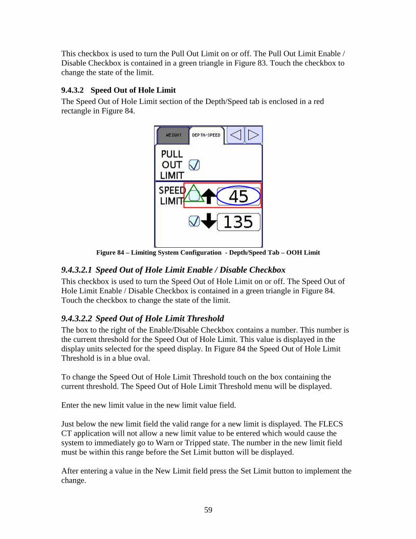
59
This checkbox is used to turn the Pull Out Limit on or off. The Pull Out Limit Enable /
Disable Checkbox is contained in a green triangle in Figure 83. Touch the checkbox to
change the state of the limit.
9.4.3.2 Speed Out of Hole Limit
The Speed Out of Hole Limit section of the Depth/Speed tab is enclosed in a red
rectangle in Figure 84.
Figure 84 – Limiting System Configuration - Depth/Speed Tab – OOH Limit
9.4.3.2.1 Speed Out of Hole Limit Enable / Disable Checkbox
This checkbox is used to turn the Speed Out of Hole Limit on or off. The Speed Out of
Hole Limit Enable / Disable Checkbox is contained in a green triangle in Figure 84.
Touch the checkbox to change the state of the limit.
9.4.3.2.2 Speed Out of Hole Limit Threshold
The box to the right of the Enable/Disable Checkbox contains a number. This number is
the current threshold for the Speed Out of Hole Limit. This value is displayed in the
display units selected for the speed display. In Figure 84 the Speed Out of Hole Limit
Threshold is in a blue oval.
To change the Speed Out of Hole Limit Threshold touch on the box containing the
current threshold. The Speed Out of Hole Limit Threshold menu will be displayed.
Enter the new limit value in the new limit value field.
Just below the new limit field the valid range for a new limit is displayed. The FLECS
CT application will not allow a new limit value to be entered which would cause the
system to immediately go to Warn or Tripped state. The number in the new limit field
must be within this range before the Set Limit button will be displayed.
After entering a value in the New Limit field press the Set Limit button to implement the
change.

60
9.4.3.3 Speed In Hole Limit
The Speed In Hole Limit section of the Depth/Speed tab is enclosed in a red rectangle in
Figure 85.
Figure 85 – Limiting System Configuration - Depth/Speed Tab – IH Limit
9.4.3.3.1 Speed In Hole Limit Enable / Disable Checkbox
This checkbox is used to turn the Speed In Hole Limit on or off. The Speed In Hole Limit
Enable / Disable Checkbox is contained in a green triangle in Figure 85. Touch the
checkbox to change the state of the limit.
9.4.3.3.2 Speed In Hole Limit Threshold
The box to the right of the Enable/Disable Checkbox contains a number. This number is
the current threshold for the Speed In Hole Limit. This value is displayed in the display
units selected for the speed display. In Figure 85 the Speed In Hole Limit Threshold is in
a blue oval.
To change the Speed In Hole Limit Threshold touch on the box containing the current
threshold. The Speed In Hole Limit Threshold menu will be displayed.
Enter the new limit value in the new limit value field.
Just below the new limit field the valid range for a new limit is displayed. The FLECS
CT application will not allow a new limit value to be entered which would cause the
system to immediately go to Warn or Tripped state. The number in the new limit field
must be within this range before the Set Limit button will be displayed.
After entering a value in the New Limit field press the Set Limit button to implement the
change.

61
9.5 Resetting Tripped Limits
This section describes the process of resetting the limiting system after a limit has been
exceeded. Failure to reset a limit using correct procedure can result in injury to personnel
and damage to equipment.
After a limit has tripped immediately reduce injector maximum pressure adjust to
minimum setting and set the injector brake. This is always the first step in resetting a
limit.
9.5.1 Reset Pull Limit
1. Set Injector Maximum Pressure to zero.
2. Set Injector Brake.
3. Note event in job log.
4. Determine why the limit tripped.
5. Verify equipment and wellhead ready to return to service.
6. Touch in the Weight constantly visible display to reset limit.
7. Turn Pull Limit On.
8. Resume Operations.
9.5.2 Reset Snub Limit
1. Set Injector Maximum Pressure to zero.
2. Set Injector Brake.
3. Note event in job log.
4. Determine why the limit tripped.
5. Verify equipment and wellhead ready to return to service.
6. Touch in the Weight constantly visible display to reset limit.
7. Turn Snub Limit On.
8. Resume Operations.
9.5.3 Reset Tag Detect Limit
1. Set Injector Maximum Pressure to zero.
2. Set Injector Brake.
3. Note event in job log.
4. Determine why the limit tripped.
5. Verify equipment and wellhead ready to return to service.
6. Touch in the Weight constantly visible display to reset limit.
7. Resume Operations.
9.5.4 Reset Pull Out Limit
1. Set Injector Maximum Pressure to zero.
2. Set Injector Brake.
3. Note event in job log.
4. Determine why the limit tripped.
5. Verify equipment and wellhead ready to return to service.
6. Touch in the Depth / Speed constantly visible display to reset limit.

62
7. Turn Pull Out Limit On.
8. Resume Operations.
9.5.5 Reset Speed Out of Hole Limit
1. Set Injector Maximum Pressure to zero.
2. Set Injector Brake.
3. Note event in job log.
4. Determine why the limit tripped.
5. Verify equipment and wellhead ready to return to service.
6. Touch in the Depth / Speed constantly visible display to reset limit.
7. Resume Operations.
9.5.6 Reset Speed In Hole Limit
1. Set Injector Maximum Pressure to zero.
2. Set Injector Brake.
3. Note event in job log.
4. Determine why the limit tripped.
5. Verify equipment and wellhead ready to return to service.
6. Touch in the Depth / Speed constantly visible display to reset limit.
7. Resume Operations.
9.6 Limit System Test
The fourth tab of the Limit Setup screen is the Test tab. This tab enables maintenance
personnel to energize the limiting system valves. The purpose of this is to verify the
valves are operating properly.
The Test tab is illustrated in Figure 86. The test tab simply has a button for beginning the
test. To begin a test press the button, read the confirmation screen and confirm or cancel.
All limits turned on will enter the system disabled state and remain in that state until the
test is ended.
Figure 86 - Limit System – Test

63
FLECS CT will not allow the limit system to be tested while the tubing is in motion. If
tubing motion is detected the Begin Test button will be disabled. The begin test button
will remain disabled until the tubing stops.
Figure 87 - Limit System - Test with Tubing in Motion
When a test is in progress the button on the Test tab will read “End Test.” To end the test
press the end test button.
Figure 88 - Limit System - End Test

64
10 System Menu The Operator uses the System Menu to perform the five functions described in detail in
the following sections: System Shutdown, KIPS Gauge Calibration, Serial Setup, Set
Time and Date, and Start/Stop RTD File.
The Operator opens the System Menu by touching in the lower right corner of the FLECS
touch screen, in the extended touchable area. See Section 1.2.2 - FLECS Display Touch-
screen (Page 6) for details on the touch-screen and extended touchable area. In addition,
the F8 key will also open the System Menu.
The unit displays the System Menu in the Context Dependent section of the FLECS
screen. The System Menu is illustrated in Figure 89.
System Setup
Close
Shutdown Set Time
KIPS
CalibrationStart Job
Serial Setup
1.2.0 Build 3 1.2.0 Build 3
Figure 89 – System Menu
To close the System Menu touch on the button labeled “Close”.
10.1 Shutdown
Prior to turning the power to the FLECS controller off the Shutdown process must be
performed. The shutdown process allows the FLECS CT application to properly prepare
for the power to be switched off. Failure to perform a System Shutdown prior to
switching the power off can cause the FLECS CT application to malfunction and cause
damage FLECS hardware.
To begin the System Shutdown process press the System Shutdown button on the System
Menu.
After a touch on the System Shutdown button the FLECS CT application displays a
confirmation dialog. When the FLECS CT application begins the shutdown process the
FLECS Controller discontinues any services it normally provides.

65
To cancel the System Shutdown process touch on the Cancel button. To confirm the
System Shutdown process touch on the Shutdown button.
The System Shutdown takes up to a minute to complete. It is critical that the power to the
FLECS controller never be interrupted while the FLECS CT application is shutting down.
Interruption of the power while shutting down can cause the FLECS CT application to
become inoperative and damage FLECS hardware. When the System Shutdown process
begins the FLECS display will indicate that the Shutdown Process is in progress.
Figure 90 – System Shutdown In Progress
After the System Shutdown process completes FLECS CT will show the message
illustrated in Figure 91. Do not turn off the power to the FLECS controller until this
message is displayed.
Figure 91 – System Shutdown Complete
In the event a problem occurs during the System Shutdown process a different message
will be displayed. This message is illustrated in Figure 92. This message indicates a
problem with the FLECS controller. The controller must be repaired before used on
another job.
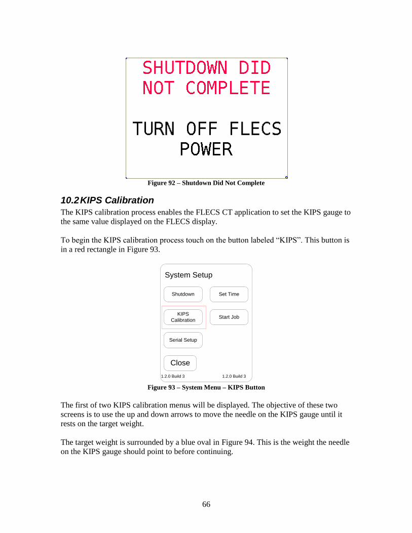
66
Figure 92 – Shutdown Did Not Complete
10.2 KIPS Calibration
The KIPS calibration process enables the FLECS CT application to set the KIPS gauge to
the same value displayed on the FLECS display.
To begin the KIPS calibration process touch on the button labeled “KIPS”. This button is
in a red rectangle in Figure 93.
System Setup
Close
Shutdown Set Time
KIPS
CalibrationStart Job
Serial Setup
1.2.0 Build 3 1.2.0 Build 3
Figure 93 – System Menu – KIPS Button
The first of two KIPS calibration menus will be displayed. The objective of these two
screens is to use the up and down arrows to move the needle on the KIPS gauge until it
rests on the target weight.
The target weight is surrounded by a blue oval in Figure 94. This is the weight the needle
on the KIPS gauge should point to before continuing.

67
The up arrows make the needle move in the clockwise direction, towards a higher pull
value. The down arrows make the needle move in the counter-clockwise direction,
towards a higher snub value.
The arrows on the left side of the menu make the needle move a large amount with one
touch. Use these two arrows to get the needle close to the target weight. The arrows on
the right side of the menu move the needle a small amount. Use these arrows to make
small adjustments to the needle until it rests on the target weight.
When the needle is as close to the target weight as possible touch on the Next button to
move to the second KIPS calibration menu. Use the up and down arrows to move the
needle to the target weight. Then touch the Done button to complete the process.
Figure 94 – KIPS Calibration
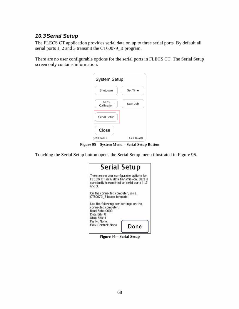
68
10.3 Serial Setup
The FLECS CT application provides serial data on up to three serial ports. By default all
serial ports 1, 2 and 3 transmit the CT60079_B program.
There are no user configurable options for the serial ports in FLECS CT. The Serial Setup
screen only contains information.
System Setup
Close
Shutdown Set Time
KIPS
CalibrationStart Job
Serial Setup
1.2.0 Build 3 1.2.0 Build 3
Figure 95 – System Menu – Serial Setup Button
Touching the Serial Setup button opens the Serial Setup menu illustrated in Figure 96.
Figure 96 – Serial Setup

69
10.3.1 CT60079_B
This section compares the output from the UNIPRO CT60079_B program to the output
from the FLECS CT application.
UNIPRO FLECS
Seconds since January 1, 1970
Seconds since January 1, 1970
Events (0-99) 0
Speed Speed
Depth Depth
Tubing Pressure Tubing Pressure
Flow Rate Custom 1 Value
Flow Total Custom 1 Total
Spare Weight Spare Weight
Wellhead Pressure Wellhead Pressure
N2 Rate Custom 2 Value
N2 Total Custom 2 Total
Weight Weight
Spare Pressure Custom 3 Value
N2 Temp Custom 4 Value
Spare Flow Custom 5 Value
Spare Total Custom 5 Total
Depth Depth
Depth Depth
Flow Total 0
CRC CRC
10.3.2 Port Settings
FLECS CT outputs serial data using the following serial port settings.
9600 bps
8 data bits
Parity: None
Stop Bits: 1
Flow control: None
10.4 Version Information
At the bottom of the System Menu the interface software version and controller software
version are displayed. The interface software version is on the left. The controller
software version is on the right.

70
10.5 Set Time and Date
The Set Time process enables the FLECS CT application to set the Time and Date for the
display and the FLECS controller stack.
To begin the Set Time process, touch on the button labeled “Set Time”. This button is in
a red rectangle in Figure 97 - System Menu - Set Time Button.
System Setup
Close
Shutdown Set Time
KIPS
CalibrationStart Job
Serial Setup
1.2.0 Build 3 1.2.0 Build 3
Figure 97 - System Menu - Set Time Button
Pressing the Set Time button opens the set time and date dialog shown in Figure 98.
7
Hour
2
Minute
18
Day
8
Month
9
Year
7:02 pm
18 Aug 2009 Set Exit
PM
Figure 98 – Set Time Menu
The screen displays the current time in the lower left hand corner. The Hour, Minute,
Day, Month, and Year are adjusted up or down with the arrows to the right of each entry.
Pressing the button in the upper right, currently “PM” will change the value to “AM.”
Once the operator has set the desired values, he or she will press Set to set the entered
values or Exit to exit without saving. The clock will be set in both the local display and
the FLECS hardware stack. After a few seconds, the display will update the current time
in the lower left hand corner.

71
10.6 Start RTD Job
The Start Job process results in the FLECS logging the data sent out the serial stream to a
local RTD file.
To begin the Start Job process, touch on the button labeled “Start Job”. This button is in a
red rectangle in Figure 99.
System Setup
Close
Shutdown Set Time
KIPS
CalibrationStart Job
Serial Setup
1.2.0 Build 3 1.2.0 Build 3
Figure 99– System Menu – Set Time Button
Once the operator enables RTD logging, the system will log the data sent out the serial
stream to a local RTD file. The operator can retrieve the file with a pen drive configured
to load the CT or Cementing software. While logging data, the display will be as shown
in Figure 100:
System Setup
Close
Shutdown RTD Running
KIPS
CalibrationEnd Job
Serial Setup
1.2.0 Build 3 1.2.0 Build 3
Figure 100 – System Menu – Set Time Button
The Set Time function is disabled and the button now states RTD Running. Likewise,
the Start Job button now states End Job. Pressing the End Job button causes the data
logging to stop and the screen reverts to the screen shown in Figure 99.

72
11 Display Backlight Brightness The Display Brightness screen enables the operator to control the intensity of the display
backlight.
The Display Brightness screen is accessible only when all other screens are closed. The
Extended Touchable Area (See 1.2.2.1, Page 6) button on the right side, second from the
bottom opens the Display Brightness screen. The screen can also be accessed by pressing
the F7 key while at the FLECS desktop (See 3.1, Page 10).
The Display Brightness screen is illustrated in Figure 101. The screen provides two preset
brightness settings, one for day use and the second for night use. Touching on one of the
two preset buttons will cause the display brightness to change to a predefined setting
which should be acceptable for most operations.
The screen also provides a control on the left side of the screen offering more precise
control of the backlight if desired.
When satisfied with the brightness level press Done. This will exit the Display Brightness
menu. The display brightness is saved at the time the screen is closed. The next time the
FLECS CT system is powered on the same brightness level will be applied.
Figure 101 - Display Brightness
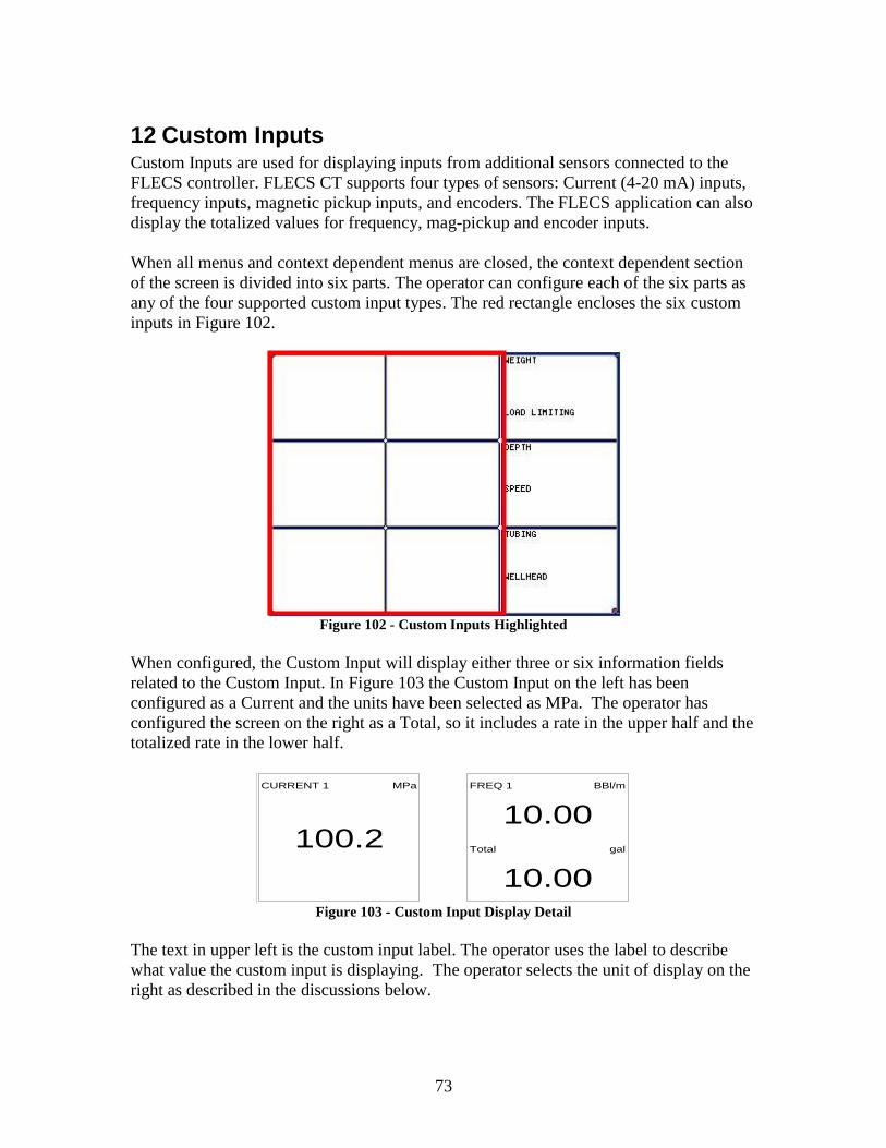
73
12 Custom Inputs Custom Inputs are used for displaying inputs from additional sensors connected to the
FLECS controller. FLECS CT supports four types of sensors: Current (4-20 mA) inputs,
frequency inputs, magnetic pickup inputs, and encoders. The FLECS application can also
display the totalized values for frequency, mag-pickup and encoder inputs.
When all menus and context dependent menus are closed, the context dependent section
of the screen is divided into six parts. The operator can configure each of the six parts as
any of the four supported custom input types. The red rectangle encloses the six custom
inputs in Figure 102.
Figure 102 - Custom Inputs Highlighted
When configured, the Custom Input will display either three or six information fields
related to the Custom Input. In Figure 103 the Custom Input on the left has been
configured as a Current and the units have been selected as MPa. The operator has
configured the screen on the right as a Total, so it includes a rate in the upper half and the
totalized rate in the lower half.
CURRENT 1 MPa
100.2
FREQ 1 BBl/m
10.00Total gal
10.00
Figure 103 - Custom Input Display Detail
The text in upper left is the custom input label. The operator uses the label to describe
what value the custom input is displaying. The operator selects the unit of display on the
right as described in the discussions below.
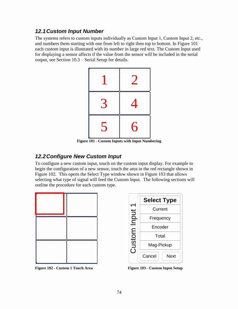
74
12.1 Custom Input Number
The systems refers to custom inputs individually as Custom Input 1, Custom Input 2, etc.,
and numbers them starting with one from left to right then top to bottom. In Figure 101
each custom input is illustrated with its number in large red text. The Custom Input used
for displaying a sensor affects if the value from the sensor will be included in the serial
output, see Section 10.3 – Serial Setup for details.
Figure 101 - Custom Inputs with Input Numbering
12.2 Configure New Custom Input
To configure a new custom input, touch on the custom input display. For example to
begin the configuration of a new sensor, touch the area in the red rectangle shown in
Figure 102. This opens the Select Type window shown in Figure 103 that allows
selecting what type of signal will feed the Custom Input. The following sections will
outline the procedure for each custom type.
Figure 102 - Custom 1 Touch Area Figure 103 - Custom Input Setup
1 2
3 4
5 6
Select Type
Current
Frequency
Encoder
Total
Mag-Pickup
Cancel Next
Custo
m Inp
ut 1

75
12.3 Custom Current
Begin by pressing the Current button in the Select Type window and press the Next
button to proceed. The system will not enable the Next button until the operator selects a
signal type.
Select Type
Current
Frequency
Encoder
Total
Mag-Pickup
Cancel Next
Custo
m Inp
ut 1
Figure 104 - Custom Input Setup
Custom Input Label Screen:
Enter up to 13 characters for the label displayed at the top of the custom input using the
FLECS display keypad and press Next.
Custom Input Label
New Label
Current 1
Remaining Characters: 4
Cancel Next
Custo
m Inp
ut 1
Figure 105 - Custom Input Label

76
Input Select Screen:
Use the left and right arrow buttons to scroll through the available signals. The system
will display the “Analog Input # Is In Use” (where # is equal to 1 through 8) message if
the channel is in use or is not configured for the desired signal type. The system will not
enable the Apply button until the operator selects an available input. Once the Apply
button is pressed, the system will advance to the next screen. The operator only uses the
Next button when modifying an existing Custom Current input.
Input Not Set
New Input
Analog Input 1
Is In Use
Cancel Next
1 Apply
Cu
sto
m In
pu
t 1
Figure 106 - Custom Analog Input
Calibration Point 1 Screen:
The custom current input uses a two-point calibration. Enter the lower calibration point
and press the Next button. The example uses a 0-500-psi pressure transducer with a
range of
4-20mA.
Calibration Point 1
mA:
4
Cancel Next
Value:
0
Cu
sto
m In
pu
t 1
Figure 107 - Custom Analog Cal Point 1

77
Calibration Point 2 Screen:
Enter the upper calibration point and press the Next button.
Calibration Point 2
mA:
20
Cancel Next
Value:
500C
usto
m In
pu
t 1
Figure 108 - Custom Analog Cal Point 2
Units Screen:
Select the desired units and press the Done button.
Select Units
Cancel Done
PSI
kPa
MPa
DegF
DegC
Cu
sto
m In
pu
t 1
Figure 109 - Custom Analog Select Units

78
After pressing the Done button the FLECS CT application will implement the new
configuration for the custom input and begin displaying the value from the sensor. The
values entered in this example result in the display shown in Figure 110. Note the label
on the left and the units on the right.
Current 1 MPa
100.2
Figure 110 - Custom Analog Displayed Values
12.4 Custom Frequency and Mag-Pickup
Begin by pressing the Frequency button in the Select Type window and press the Next
button to proceed. The system will not enable the Next button until the operator selects a
signal type.
Select Type
Current
Frequency
Encoder
Total
Mag-Pickup
Cancel Next
Cu
sto
m In
pu
t 1
Figure 111 - Select Type Frequency

79
Custom Input Label Screen:
Enter up to 13 characters for the label displayed at the top of the custom input using the
FLECS display keypad and press Next.
Custom Input Label
New Label
FREQ 1
Remaining Characters: 9
Cancel Next
Cu
sto
m In
pu
t 1
Figure 112 - Custom Input Label - Frequency
Input Select Screen:
This screen is the only difference between the Frequency and Mag-Pickup setup. A
FLECS configuration file determines what signals are configured for each type. Use the
left and right arrow buttons to scroll through the available signals. The system will
display the “Input Q# Is In Use” (where # is equal to 1 through 8) message if the channel
is in use or is not configured for the desired signal type. The system will not enable the
Apply button until the operator selects an available input. Once the Apply button is
pressed, the system will advance to the next screen. The operator only uses the Next
button when modifying an existing Custom Frequency input.
Input Not Set
New Input
Input Q1 Is In Use
Cancel Next
1 Apply
Cu
sto
m In
pu
t 1
Figure 113 - Input Select - Frequency
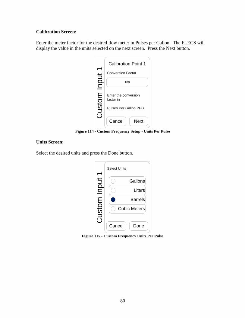
80
Calibration Screen:
Enter the meter factor for the desired flow meter in Pulses per Gallon. The FLECS will
display the value in the units selected on the next screen. Press the Next button.
Calibration Point 1
Conversion Factor
100
Cancel Next
Enter the conversion
factor in
Pulses Per Gallon PPG
Cu
sto
m In
pu
t 1
Figure 114 - Custom Frequency Setup - Units Per Pulse
Units Screen:
Select the desired units and press the Done button.
Select Units
Cancel Done
Gallons
Liters
Barrels
Cubic Meters
Cu
sto
m In
pu
t 1
Figure 115 - Custom Frequency Units Per Pulse

81
After pressing the Done button the FLECS CT application will implement the new
configuration for the custom input and begin displaying the value from the sensor.
The values entered in this example result in the display shown in Figure 116. Note the
label on the left and the units on the right.
FREQ 1 BBl/m
10.00
Figure 116 - Custom Frequency Setup – Displayed Values
12.5 Custom Encoder
Begin by pressing the Encoder button in the Select Type window and press the Next
button to proceed. The system will not enable the Next button until the operator selects a
signal type.
Select Type
Current
Frequency
Encoder
Total
Mag-Pickup
Cancel Next
Cu
sto
m In
pu
t 1
Figure 117 - Select Type Encoder
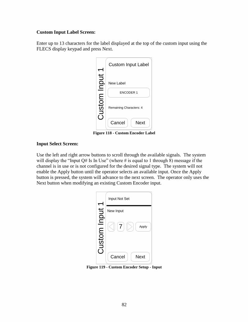
82
Custom Input Label Screen:
Enter up to 13 characters for the label displayed at the top of the custom input using the
FLECS display keypad and press Next.
Custom Input Label
New Label
ENCODER 1
Remaining Characters: 4
Cancel Next
Cu
sto
m In
pu
t 1
Figure 118 - Custom Encoder Label
Input Select Screen:
Use the left and right arrow buttons to scroll through the available signals. The system
will display the “Input Q# Is In Use” (where # is equal to 1 through 8) message if the
channel is in use or is not configured for the desired signal type. The system will not
enable the Apply button until the operator selects an available input. Once the Apply
button is pressed, the system will advance to the next screen. The operator only uses the
Next button when modifying an existing Custom Encoder input.
Input Not Set
New Input
Cancel Next
7 Apply
Cu
sto
m In
pu
t 1
Figure 119 - Custom Encoder Setup - Input

83
Calibration Screen:
Enter the counts per revolution (typically 500) of the encoder and the number of feet per
revolution of the depth counter (typically 2 ft). The FLECS will display the value in the
units selected on the next screen. Press the Next button.
Calibration
Count Per Revolution
500
Cancel Next
Feet Per Revolution
2
Cu
sto
m In
pu
t 1
Figure 120 - Custom Encoder Setup - PPR & UPR
Units Screen:
Select the desired units and press the Done button.
Select Units
Cancel Done
Feet
Meters
Cu
sto
m In
pu
t 1
Figure 121 - Custom Encoder Displayed Units

84
After pressing the Done button the FLECS CT application will implement the new
configuration for the custom input and begin displaying the value from the sensor.
The values entered in this example result in the display shown in Figure 122. Note the
label on the left and the units on the right.
ENCODER 1 m/min
10.00
Figure 122 - Custon Encoder Display Value
12.6 Custom Total – Frequency or Mag-Pickup
Begin by pressing the Total button in the Select Type window and press the Next button
to proceed. The system will not enable the Next button until the operator selects a signal
type.
Select Type
Current
Frequency
Encoder
Total
Mag-Pickup
Cancel Next
Cu
sto
m In
pu
t 1
Figure 123 - Custom Total Selection

85
Custom Input Label Screen:
Enter up to 13 characters for the label displayed at the top of the custom input using the
FLECS display keypad and press Next.
Custom Input Label
New Label
TOTAL 1
Remaining Characters: 6
Cancel Next
Cu
sto
m In
pu
t 1
Figure 124 - Custom Total Label
Total Select Input Type
Select either the Frequency or the Mag-Pickup button; the system will advance to the
next screen as soon as the operator selects a button.
Select Input Type
Cancel
Frequency
Encoder
Mag-Pickup
Cu
sto
m In
pu
t 1
Figure 125 - Custom Total Input Type

86
Input Select Screen:
This screen is the only difference between the Frequency and Mag-Pickup setup. A
FLECS configuration file determines what signals are configured for each type. Use the
left and right arrow buttons to scroll through the available signals. The system will
display the “Input Q# Is In Use” (where # is equal to 1 through 8) message if the channel
is in use or is not configured for the desired signal type. The system will not enable the
Apply button until the operator selects an available input. Once the Apply button is
pressed, the system will advance to the next screen. The operator only uses the Next
button when modifying an existing Custom Frequency input.
Input Not Set
New Input
Input Q1 Is In Use
Cancel Next
1 Apply
Cu
sto
m In
pu
t 1
Figure 126 - Custom Total Input Select
Calibration Screen:
Enter the meter factor for the desired flow meter in Pulses per Gallon. The FLECS will
display the value in the units selected on the next screen. Press the Next button.
Calibration Point 1
Conversion Factor
100
Cancel Next
Enter the conversion
factor in
Pulses Per Gallon PPG
Cu
sto
m In
pu
t 1
Figure 127 – Custom Total Frequency Calibration

87
Rate Units Screen:
Select the desired units and press the Done button.
Select Units
Cancel Done
Gallons
Liters
Barrels
Cubic MetersC
usto
m In
pu
t 1
Figure 128 - Custom Total Rate Units
Totalizer Units Screen:
Select the desired units and press the Done button.
Select Totalizing Units
Done
Gallons
Liters
Barrels
Cubic Meters
Cu
sto
m In
pu
t 1
Figure 129 - Custom Total Totalizing Units

88
After pressing the Done button the FLECS CT application will implement the new
configuration for the custom input and begin displaying the value from the sensor.
The values entered in this example result in the display shown in Figure 130. Note the
labels on the left and the units on the right.
FREQ 1 BBl/m
10.00Total gal
10.00
Figure 130 - Custom Units Frequency Display
12.7 Custom Total - Encoder
Begin by pressing the Total button in the Select Type window and press the Next button
to proceed. The system will not enable the Next button until the operator selects a signal
type.
Select Type
Current
Frequency
Encoder
Total
Mag-Pickup
Cancel Next
Cu
sto
m In
pu
t 1
Figure 131 - Custom Total

89
Custom Input Label Screen:
Enter up to 13 characters for the label displayed at the top of the custom input using the
FLECS display keypad and press Next.
Custom Input Label
New Label
ENCODER 1
Remaining Characters: 4
Cancel Next
Cu
sto
m In
pu
t 1
Figure 132 - Custom Total Label
Select Signal Type
Select the Encoder button; the system will advance to the next screen as soon as the
operator selects a button.
Select Input Type
Cancel
Frequency
Encoder
Mag-Pickup
Cu
sto
m In
pu
t 1
Figure 133 - Custom Total Input Type

90
Input Select Screen:
Use the left and right arrow buttons to scroll through the available signals. The system
will display the “Input Q# Is In Use” (where # is equal to 1 through 8) message if the
channel is in use or is not configured for the desired signal type. The system will not
enable the Apply button until the operator selects an available input. Once the Apply
button is pressed, the system will advance to the next screen. The operator only uses the
Next button when modifying an existing Custom Encoder input.
Input Not Set
New Input
Input Q1 Is In Use
Cancel Next
1 Apply
Cu
sto
m In
pu
t 1
Figure 134 - Custom Total Input Select
Calibration Screen:
Enter the counts per revolution (typically 500) of the encoder and the number of feet per
revolution of the depth counter (typically 2 ft). The FLECS will display the value in the
units selected on the next screen. Press the Next button.
Calibration
Count Per Revolution
500
Cancel Next
Feet Per Revolution
2
Cu
sto
m In
pu
t 1
Figure 135 - Custom Total Encoder Calibration

91
Units Screen:
Select the desired units and press the Next button.
Select Units
Cancel Done
Feet
Meters
Cu
sto
m In
pu
t 1
Figure 136 - Custom Total Encoder Units
Totalized Units Screen:
Select the desired units and press the Done button.
Select Totalizing Units
Done
Feet
Meters
Cu
sto
m In
pu
t 1
Figure 137 - Custom Total Totalizing Units

92
After pressing the Done button the FLECS CT application will implement the new
configuration for the custom input and begin displaying the value from the sensor.
The values entered in this example result in the display shown in Figure 130. Note the
label on the left and the units on the right.
ENCODER 1 m/m
10.00Total feet
10.00
Figure 138 - Custom Total Encoder Display
12.8 Zero Custom Total
To zero a Custom Total input touch on the custom input. The Modify Custom Input
screen will be displayed. If the custom input touched on was a total there will be a button
labeled “Zero”. Press the zero button to zero the custom total.
12.9 Modify Custom Input
To modify the setup of a custom input touch on the custom input to be modified. The
Custom Input Modify screen is displayed. Press the button labeled “Modify” to modify
the existing configuration.
12.10 Disable Custom Input
To disable a custom input touch on the custom input to be disabled. The Custom Input
Modify screen is displayed. Press the button labeled “Disable” to disable the custom
input.
13 Latest Software The latest release of the FLECS CT application can be obtained from the FLECS Systems
page on HalWorld. This page can be accessed from either the PE Electronic Technicians
portal or the Coiled Tubing / HWO portal. From the links sections of the portal look for
the FLECS Systems link.

93
Table of Figures
Figure 1 - FLECS Display with Screen Highlighted 5
Figure 2 - FLECS Display with Touch-Screen Highlighted 6
Figure 3 - FLECS Display with Extended Touchable Area Highlighted 6
Figure 4 - FLECS Display with Keypad Highlighted 7
Figure 5 – Key with Primary and Shifted Function Illustrated 7
Figure 6 – Power Indicator, Illuminated 8
Figure 7 – FLECS CT Display with Constantly Visible Display Highlighted 8
Figure 8 – FLECS CT Display with Context Dependent Display Highlighted 9
Figure 9 – FLECS CT with Context Menu Button Highlighted 10
Figure 10 - Desktop Key Hint Label Illustration 11
Figure 11 - Key Hint Label Illustration 12
Figure 12 – Add Calibration Point mA 13
Figure 13 – Add Calibration Point mA – Range Bar Detail – No Existing Points 13
Figure 14 – Add Calibration Point mA – Existing Point 14
Figure 15 – Add Calibration Point mA – Entered Point Indicator 15
Figure 16 – Add Calibration Point mA– Invalid Point Entered 15
Figure 17 – Add Calibration Point Value 16
Figure 18 – Add Calibration Point Value 16
Figure 19 – Add Calibration Point Value – Entered Point Indicator 17
Figure 20 - Delete Calibration Point Confirmation 18
Figure 21 - Connection Selection - Input Not Set 19
Figure 22 - Connection Selection - Input Selected 19
Figure 23 – Weight Display 20
Figure 24 – Weight Display, Current Weight & Units Highlighted 20
Figure 25 – Weight Display – Load Limiting Status Highlighted 21
Figure 26 - Weight Display Configuration Menu 21
Figure 27 - Load Pin Setup - No Pins Configured 22
Figure 28 - Load Pin Setup - Single Pin 22
Figure 29 - Load Pin Setup - Two Pins - Pin 1 Selected 23
Figure 30 - Load Pin Setup - Two Pins - Pin 2 Selected 23
Figure 31 - Load Pin Setup - Calibration Tab 24
Figure 32 - Load Pin Setup - Calibration Tab with Points 24
Figure 33 – Load Pin Status, No Pins Configured 26
Figure 34 – Load Pin Status, One Pin Configured, Pin Input Not Configured 26
Figure 35 – Load Pin Status, One Pin Configured, Pin Signal Displayed 26
Figure 36 – Load Pin Status, Two Pins Configured, Pin Signal Displayed 26
Figure 37 – Zero Weight Confirmation - Normal 27
Figure 38 - Zero Weight Confirmation - Large Offset 27
Figure 39 - Zero Weight Confirmation - Depth Warning 28
Figure 40 - Weight Unit Selection Area 28
Figure 41 – Depth & Speed Display 29
Figure 42 – Depth & Speed Display – Depth & Units Highlighted 29
Figure 43 – Depth & Speed Display – Out of Hole 30
Figure 44 – Depth & Speed Display – In Hole 30
Figure 45 – Depth & Speed Display – No Movement 31

94
Figure 46 - Depth & Speed Display - Limit Status Area 31
Figure 47 – Depth & Speed Display Configuration Menu 31
Figure 48 - Encoder Setup - Input Tab 32
Figure 49 – Encoder Setup – Calibration Tab 33
Figure 50 – Depth & Speed Configuration – Depth Unit Buttons Highlighted 33
Figure 51 – Depth & Speed Configuration – Speed Unit Buttons Highlighted 34
Figure 52 – Depth & Speed Configuration – Zero Depth 35
Figure 53 – Depth & Speed Configuration Context Menu – Set Depth 35
Figure 54 – Set Current Depth 36
Figure 55 – Pressure Display 37
Figure 56 – Pressure Display – Tubing Pressure 38
Figure 57 – Pressure Display – Wellhead Pressure 38
Figure 58 – Pressure Display Configuration 39
Figure 59 – Pressure Display Configuration – Tubing Status 39
Figure 60 – Pressure Display Configuration – Tubing Display Unit 40
Figure 61 – Pressure Display Configuration – Zero 40
Figure 62 – Confirm Zero Pressure 41
Figure 63 – Cannot Zero Pressure – High Signal 41
Figure 64 – Cannot Zero Pressure – Low Signal 42
Figure 65 – Cannot Zero Pressure – No Signal 42
Figure 66 – Tubing Pressure Setup – Calibration Tab 43
Figure 67 – Transducer Setup - Calibration Point List 43
Figure 68 – Transducer Setup – Add Point Button 44
Figure 69 – All Limits Off 46
Figure 70 – All Limits On 46
Figure 71 – Warn State 47
Figure 72 – System Disabled State 48
Figure 73 – Tripped State 49
Figure 74 – Limiting System Tabs 53
Figure 75 – Limiting System Configuration – Output Configuration 54
Figure 76 – Limiting System Configuration - Weight Tab 54
Figure 77 – Limiting System Configuration - Weight Tab – Pull Limit 55
Figure 78 – Pull Limit Threshold 55
Figure 79 – Limiting System Configuration - Weight Tab – Snub Limit 56
Figure 80 – Snub Limit Threshold 57
Figure 81 – Limiting System Configuration - Weight Tab – Tag Limit 57
Figure 82 – Limiting System Configuration - Depth/Speed Tab 58
Figure 83 – Limiting System Configuration - Depth/Speed Tab – Pull Out Limit 58
Figure 84 – Limiting System Configuration - Depth/Speed Tab – OOH Limit 59
Figure 85 – Limiting System Configuration - Depth/Speed Tab – IH Limit 60
Figure 86 - Limit System – Test 62
Figure 87 - Limit System - Test with Tubing in Motion 63
Figure 88 - Limit System - End Test 63
Figure 89 – System Menu 64
Figure 90 – System Shutdown In Progress 65
Figure 91 – System Shutdown Complete 65

95
Figure 92 – Shutdown Did Not Complete 66
Figure 93 – System Menu – KIPS Button 66
Figure 94 – KIPS Calibration 67
Figure 95 – System Menu – Serial Setup Button 68
Figure 96 – Serial Setup 68
Figure 97 - System Menu - Set Time Button 70
Figure 98 – Set Time Menu 70
Figure 99– System Menu – Set Time Button 71
Figure 100 – System Menu – Set Time Button 71
Figure 101 - Custom Inputs with Input Numbering 74
Figure 102 - Custom 1 Touch Area Figure 103 - Custom Input Setup 74
Figure 104 - Custom Input Setup 75
Figure 105 - Custom Input Label 75
Figure 106 - Custom Analog Input 76
Figure 107 - Custom Analog Cal Point 1 76
Figure 108 - Custom Analog Cal Point 2 77
Figure 109 - Custom Analog Select Units 77
Figure 110 - Custom Analog Displayed Values 78
Figure 111 - Select Type Frequency 78
Figure 112 - Custom Input Label - Frequency 79
Figure 113 - Input Select - Frequency 79
Figure 114 - Custom Frequency Setup - Units Per Pulse 80
Figure 115 - Custom Frequency Units Per Pulse 80
Figure 116 - Custom Frequency Setup – Displayed Values 81
Figure 117 - Select Type Encoder 81
Figure 118 - Custom Encoder Label 82
Figure 119 - Custom Encoder Setup - Input 82
Figure 120 - Custom Encoder Setup - PPR & UPR 83
Figure 121 - Custom Encoder Displayed Units 83
Figure 122 - Custon Encoder Display Value 84
Figure 123 - Custom Total Selection 84
Figure 124 - Custom Total Label 85
Figure 125 - Custom Total Input Type 85
Figure 126 - Custom Total Input Select 86
Figure 127 – Custom Total Frequency Calibration 86
Figure 128 - Custom Total Rate Units 87
Figure 129 - Custom Total Totalizing Units 87
Figure 130 - Custom Units Frequency Display 88
Figure 131 - Custom Total 88
Figure 132 - Custom Total Label 89
Figure 133 - Custom Total Input Type 89
Figure 134 - Custom Total Input Select 90
Figure 135 - Custom Total Encoder Calibration 90
Figure 136 - Custom Total Encoder Units 91
Figure 137 - Custom Total Totalizing Units 91
Figure 138 - Custom Total Encoder Display 92

96