flexible learning approach to physics ÊÊÊ module p4.3 ... · module p4.3 electromagnetic forces...
TRANSCRIPT
F L E X I B L E L E A R N I N G A P P R O A C H T O P H Y S I C S
FLAP P4.3 Electromagnetic forcesCOPYRIGHT © 1998 THE OPEN UNIVERSITY S570 V1.1
Module P4.3 Electromagnetic forces1 Opening items
1.1 Module introduction1.2 Fast track questions1.3 Ready to study?
2 Magnetic forces on a current carrying conductor2.1 Force on a straight current carrying wire in a
uniform magnetic field2.2 The magnetic torque on a coil carrying a current2.3 Some applications of magnetic forces: motors and
meters2.4 Forces between currents and the definition of the
ampere
3 Magnetic forces on a moving charged particle3.1 The magnetic force on an electron in a wire3.2 The magnetic force on a moving charged particle3.3 Motion of a charge along or perpendicular to a
uniform magnetic field
3.4 Motion in a uniform magnetic field: the general case
4 The electromagnetic force4.1 The Lorentz force law
5 Some applications of the Lorentz force5.1 Measuring the charge-to-mass ratio of the electron5.2 The velocity selector5.3 The mass spectrometer5.4 The electromagnetic flowmeter5.5 The Hall effect
6 Closing items6.1 Module summary6.2 Achievements6.3 Exit test
Exit module
FLAP P4.3 Electromagnetic forcesCOPYRIGHT © 1998 THE OPEN UNIVERSITY S570 V1.1
1 Opening items
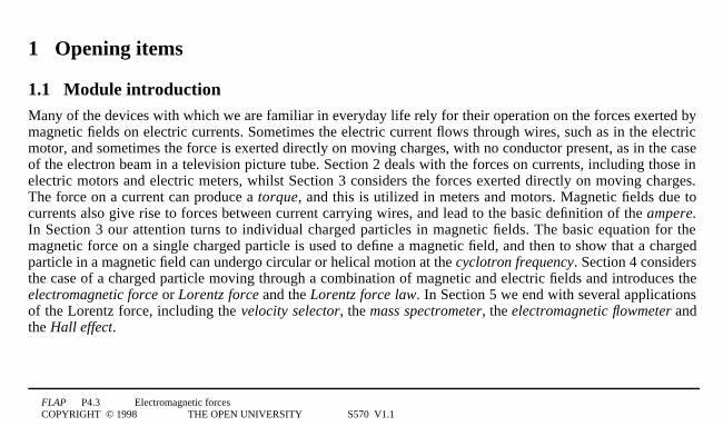
1.1 Module introductionMany of the devices with which we are familiar in everyday life rely for their operation on the forces exerted bymagnetic fields on electric currents. Sometimes the electric current flows through wires, such as in the electricmotor, and sometimes the force is exerted directly on moving charges, with no conductor present, as in the caseof the electron beam in a television picture tube. Section 2 deals with the forces on currents, including those inelectric motors and electric meters, whilst Section 3 considers the forces exerted directly on moving charges.The force on a current can produce a torque, and this is utilized in meters and motors. Magnetic fields due tocurrents also give rise to forces between current carrying wires, and lead to the basic definition of the ampere.In Section 3 our attention turns to individual charged particles in magnetic fields. The basic equation for themagnetic force on a single charged particle is used to define a magnetic field, and then to show that a chargedparticle in a magnetic field can undergo circular or helical motion at the cyclotron frequency. Section 4 considersthe case of a charged particle moving through a combination of magnetic and electric fields and introduces theelectromagnetic force or Lorentz force and the Lorentz force law. In Section 5 we end with several applicationsof the Lorentz force, including the velocity selector, the mass spectrometer, the electromagnetic flowmeter andthe Hall effect.
FLAP P4.3 Electromagnetic forcesCOPYRIGHT © 1998 THE OPEN UNIVERSITY S570 V1.1
Study comment Having read the introduction you may feel that you are already familiar with the material covered by thismodule and that you do not need to study it. If so, try the Fast track questions given in Subsection 1.2. If not, proceeddirectly to Ready to study? in Subsection 1.3.
FLAP P4.3 Electromagnetic forcesCOPYRIGHT © 1998 THE OPEN UNIVERSITY S570 V1.1
1.2 Fast track questions
Study comment Can you answer the following Fast track questions?. If you answer the questions successfully you needonly glance through the module before looking at the Module summary (Subsection 6.1) and the Achievements listed inSubsection 6.2. If you are sure that you can meet each of these achievements, try the Exit test in Subsection 6.3. If you havedifficulty with only one or two of the questions you should follow the guidance given in the answers and read the relevantparts of the module. However, if you have difficulty with more than two of the Exit questions you are strongly advised tostudy the whole module.
Question F1
A particle of mass m and charge q moves with velocity v into a region of uniform magnetic field B at an angle θtο B. Show that the resultant path is a helix. Obtain expressions for the period of the motion and for the pitch ofthe helix.
Question F2
Explain why a commutator is needed to feed the current to the coil of a simple d.c. motor. Describe a split ringcommutator and its function.
FLAP P4.3 Electromagnetic forcesCOPYRIGHT © 1998 THE OPEN UNIVERSITY S570 V1.1
Question F3
A beam of positive ions, all having the same charge q but of various speeds and masses, passes through a regionof uniform electric and magnetic fields which are perpendicular to one another and to the initial beam direction.Show that only those ions with a certain speed will pass undeflected through the field region and evaluate thatspeed.
Question F4
Two long straight wires are placed parallel to one another at a separation of r = 121cm. Wire 1 has a currentI1 = 21A; wire 2 has a current I2 = 81A. Both currents are in the same direction. Find the force on a 101cm lengthof each wire (use µ0 = 4π × 10−71T1m1A−1). Will the force be attractive or repulsive?
Question F5
A uniform magnetic field of 0.081T produces a Hall voltage VHall = 2.61mV when there is a current of 101mA in arectangular specimen of a semiconductor. The thickness of the specimen, measured in the direction of themagnetic field, is 0.51mm. Establish the necessary equations and find the concentration of mobile chargedparticles in the specimen.
FLAP P4.3 Electromagnetic forcesCOPYRIGHT © 1998 THE OPEN UNIVERSITY S570 V1.1
Study comment Having seen the Fast track questions you may feel that it would be wiser to follow the normal routethrough the module and to proceed directly to Ready to study? in Subsection 1.3.
Alternatively, you may still be sufficiently comfortable with the material covered by the module to proceed directly to theClosing items.
FLAP P4.3 Electromagnetic forcesCOPYRIGHT © 1998 THE OPEN UNIVERSITY S570 V1.1
1.3 Ready to study?
Study comment In order to study this module, you will need to be familiar with the following terms: atom, centripetalacceleration, centripetal force, centre of mass, charge, component (of a vector), electric current, electric field, electric force,electron, frequency, ion, line of action of a force, magnetic field, magnitude (of a vector), Newton’s laws of motion, period,potential difference, speed, vector, velocity and you should be able to describe the magnetic field due to a current in a longstraight wire. If you are uncertain about any of these terms then you can review them now by reference to the Glossary,which will also indicate where in FLAP they are developed. The following Ready to study questions will allow you toestablish whether you need to review some of the topics before embarking on this module.
FLAP P4.3 Electromagnetic forcesCOPYRIGHT © 1998 THE OPEN UNIVERSITY S570 V1.1
Question R1
A ball has a velocity of 20.01m1s–1 at an angle of 55° above the horizontal. Find the horizontal and verticalcomponents of its velocity.
Question R2
The passengers on a fairground ride move in a horizontal circle of 8.01m radius, taking 7.01s to complete oneorbit. What is their centripetal acceleration? What would be the period to complete an orbit for the centripetalacceleration to be 9.81m1s−2 (i.e. one g)?
FLAP P4.3 Electromagnetic forcesCOPYRIGHT © 1998 THE OPEN UNIVERSITY S570 V1.1
Question R3
(a) Describe, as fully as possible, the configuration of the magnetic field produced by a direct current I in a longstraight wire. (Consult the answer to this part of the question before attempting part (b).)
(b) Two long straight parallel wires, separated by a distance of one metre, carry currents of 5 and 101A, in thesame direction. Find the position on the perpendicular line joining the wires where the magnetic field is zero.
Question R4
A potential difference of 1001V is applied between two parallel plates 201cm apart. What is the electric fieldbetween the plates? Calculate the magnitude of the force on an electron between the plates. ☞ How would theforce on a doubly-charged helium ion (He2+) between the plates differ from that on an electron?
FLAP P4.3 Electromagnetic forcesCOPYRIGHT © 1998 THE OPEN UNIVERSITY S570 V1.1
2 Magnetic forces on a current carrying conductor
2.1 Force on a straight current carrying wire in a uniform magnetic field
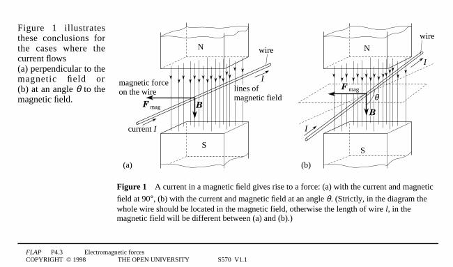
If a current carrying wire is placed within a uniform magnetic field, ☞ such as that between the poles of amagnet, then a magnetic force F mag is found to act on the wire. The magnetic field is a vector quantity,represented as B, and its magnitude B is called the magnetic field strength. ☞ If we investigate how themagnitude Fmag and direction of the force Fmag change with the length l of the wire and the magnitude anddirection of both the current and the magnetic field, we reach the following conclusions:
1 The direction of the force Fmag is always perpendicular to the direction of the current and to the direction ofthe magnetic field B.
Note The direction of a magnetic field is taken to be the direction in which the North pole of a freely suspended compassneedle would point in the field.
FLAP P4.3 Electromagnetic forcesCOPYRIGHT © 1998 THE OPEN UNIVERSITY S570 V1.1
2 The magnitude of the force Fmag increases linearly with the length l of the wire in a uniform magnetic field.
Note A magnetic field is said to be uniform in some region if it has the same magnitude and direction at every point withinthat region. Such a field can be produced (a) between the poles of a permanent magnet or an electromagnet which has polepieces whose diameter is large compared to their separation; (b) in the central region of a long solenoid; (c) in the centralregion between two coils whose separation is equal to the coil radius 1—1an arrangement devised by Helmholtz. The Earth’sfield is also fairly uniform over a small region.
3 The magnitude of the force, Fmag, increases linearly with the magnitude of the current I in the wire. ☞4 The magnitude of the force, Fmag, increases linearly with the magnitude of the magnetic field (i.e. with the
magnetic field strength, B).
5 If we reverse the direction of either the field or the current, we reverse the direction of the force; if wereverse both the field and the current together, the direction of the force is unchanged.
Note The conventional direction of current is that in which positive charge appears to be moving, i.e. opposite to thedirection of the electron flow.
6 If the wire is positioned so that the current flow is at an angle θ to the magnetic field we find that themagnitude of the force is reduced, but it remains perpendicular to the current direction and to the magneticfield direction. If the current flow is parallel or opposite to the direction of the magnetic field, then we findthat the force becomes zero. At any angle θ the force is proportional to sin1θ.
FLAP P4.3 Electromagnetic forcesCOPYRIGHT © 1998 THE OPEN UNIVERSITY S570 V1.1
F1mag
N
S
B
magnetic forceon the wire
current I
wire
lines of magnetic field
N
S
I
wire
I
B
θF1mag
I
(a) (b)
Figure 14A current in a magnetic field gives rise to a force: (a) with the current and magnetic
field at 90°, (b) with the current and magnetic field at an angle θ. (Strictly, in the diagram thewhole wire should be located in the magnetic field, otherwise the length of wire l, in themagnetic field will be different between (a) and (b).)
Figure 1 illustratesthese conclusions forthe cases where thecurrent flows (a) perpendicular to themagnetic field or(b) at an angle θ to themagnetic field.
FLAP P4.3 Electromagnetic forcesCOPYRIGHT © 1998 THE OPEN UNIVERSITY S570 V1.1
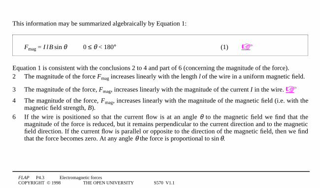
This information may be summarized algebraically by Equation 1:
Fmag = I1l1B1sin1θ 0 ≤ θ < 180° (1) ☞
Equation 1 is consistent with the conclusions 2 to 4 and part of 6 (concerning the magnitude of the force).2 The magnitude of the force Fmag increases linearly with the length l of the wire in a uniform magnetic field.
3 The magnitude of the force, Fmag, increases linearly with the magnitude of the current I in the wire. ☞
4 The magnitude of the force, Fmag, increases linearly with the magnitude of the magnetic field (i.e. with themagnetic field strength, B).
6 If the wire is positioned so that the current flow is at an angle θ to the magnetic field we find that themagnitude of the force is reduced, but it remains perpendicular to the current direction and to the magneticfield direction. If the current flow is parallel or opposite to the direction of the magnetic field, then we findthat the force becomes zero. At any angle θ the force is proportional to sin1θ.
FLAP P4.3 Electromagnetic forcesCOPYRIGHT © 1998 THE OPEN UNIVERSITY S570 V1.1
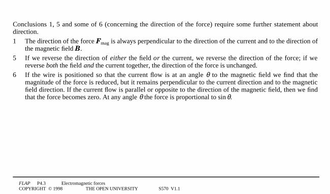
Conclusions 1, 5 and some of 6 (concerning the direction of the force) require some further statement aboutdirection.
1 The direction of the force Fmag is always perpendicular to the direction of the current and to the direction ofthe magnetic field B.
5 If we reverse the direction of either the field or the current, we reverse the direction of the force; if wereverse both the field and the current together, the direction of the force is unchanged.
6 If the wire is positioned so that the current flow is at an angle θ to the magnetic field we find that themagnitude of the force is reduced, but it remains perpendicular to the current direction and to the magneticfield direction. If the current flow is parallel or opposite to the direction of the magnetic field, then we findthat the force becomes zero. At any angle θ the force is proportional to sin1θ.
FLAP P4.3 Electromagnetic forcesCOPYRIGHT © 1998 THE OPEN UNIVERSITY S570 V1.1
N
S
(b)
I
wire
I
B
θF mag
Figure 1b4A current in a magnetic fieldgives rise to a force with the current andmagnetic field at an angle θ. (Strictly, inthe diagram the whole wire should belocated in the magnetic field)
Fmag
Il
B
θ
Figure 24The corkscrew rule,as applied to the vectorsrepresenting the situation shownin Figure 1b. B and I0l are in aplane perpendicular to F.
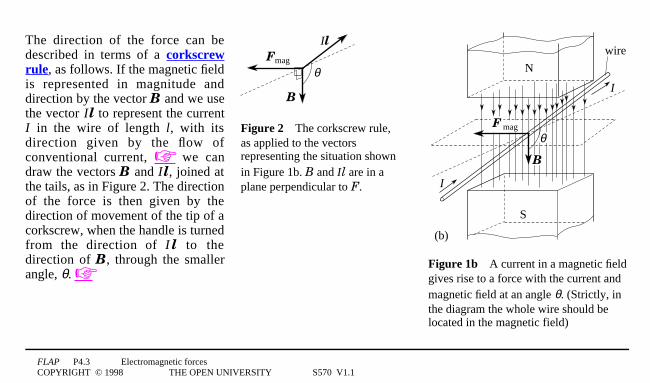
The direction of the force can bedescribed in terms of a corkscrewrule, as follows. If the magnetic fieldis represented in magnitude anddirection by the vector B and we usethe vector I0l to represent the currentI in the wire of length l, with itsdirection given by the flow ofconventional current, ☞ we candraw the vectors B and I 0l, joined atthe tails, as in Figure 2. The directionof the force is then given by thedirection of movement of the tip of acorkscrew, when the handle is turnedfrom the direction of I 0l to thedirection of B, through the smallerangle, θ. ☞
FLAP P4.3 Electromagnetic forcesCOPYRIGHT © 1998 THE OPEN UNIVERSITY S570 V1.1
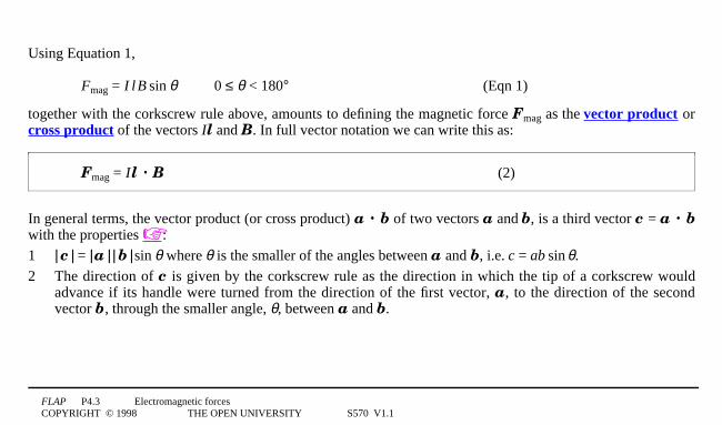
Using Equation 1,
Fmag = I1l1B1sin1θ 0 ≤ θ < 180° (Eqn 1)
together with the corkscrew rule above, amounts to defining the magnetic force Fmag as the vector product orcross product of the vectors Il and B. In full vector notation we can write this as:
Fmag = I0l · B (2)
In general terms, the vector product (or cross product) a · b of two vectors a and b, is a third vector c = a · bwith the properties ☞:
1 |1c1| = |1a1|1|1b1|1sin1θ where θ is the smaller of the angles between a and b, i.e. c = ab1sin1θ.
2 The direction of c is given by the corkscrew rule as the direction in which the tip of a corkscrew wouldadvance if its handle were turned from the direction of the first vector, a, to the direction of the secondvector b, through the smaller angle, θ, between a and b.
FLAP P4.3 Electromagnetic forcesCOPYRIGHT © 1998 THE OPEN UNIVERSITY S570 V1.1
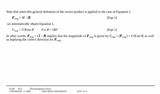
Note that when this general definition of the vector product is applied to the case of Equation 2
Fmag = I0l · B (Eqn 2)
we automatically obtain Equation 1.
Fmag = I1l1B1sin1θ 0 ≤ θ < 180° (Eqn 1)
In other words, Fmag = I1l · B implies that the magnitude of Fmag is given by Fmag = |1Fmag1| = I1l1B1sin1θ, as wellas implying the correct direction for Fmag.
FLAP P4.3 Electromagnetic forcesCOPYRIGHT © 1998 THE OPEN UNIVERSITY S570 V1.1
The SI unit for magnetic field strength, defined by Equation 1 is called the tesla, T: ☞
1 unit of magnetic field strength = 11T = 11N1A−11m−1
Question T1A straight portion of wire, 151cm long, carrying a current of 2 1A at right angles to a uniform magnetic field,experiences a force of 0.041N. Find the magnetic field strength.4❏
Question T2
A wire of length 0.751m lies along the z-axis and carries a current of 4 1A in the positive z-direction. A uniformmagnetic field throughout the region, has components Bx = 0.21T, By = 0.41T, Bz = 0.61T. Which components of Binfluence the force on the wire? Find the components of this magnetic force and hence the resultant force.4❏
FLAP P4.3 Electromagnetic forcesCOPYRIGHT © 1998 THE OPEN UNIVERSITY S570 V1.1
O
P
F
(a)
φ
rr 1sin1φ
F1sin1φ
O
P
F
(b)
r⊥
Figure 34(a) The turning effect or torque about O produced by a forceF applied at displacement r from O. The plane containing the vectors rand F is shown and φ is the smaller angle between these two vectors.(b) Closing a heavy door with the optimum position and angle of anapplied force.
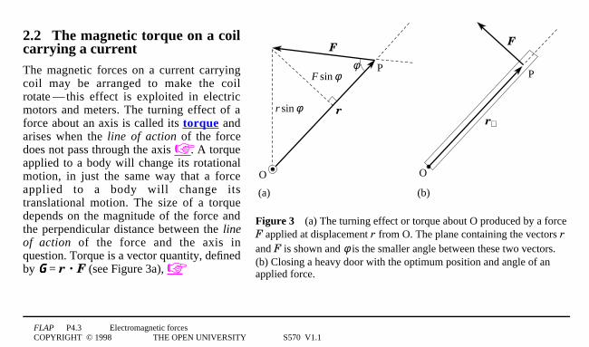
2.2 The magnetic torque on a coilcarrying a currentThe magnetic forces on a current carryingcoil may be arranged to make the coilrotate1—1this effect is exploited in electricmotors and meters. The turning effect of aforce about an axis is called its torque andarises when the line of action of the forcedoes not pass through the axis ☞. A torqueapplied to a body will change its rotationalmotion, in just the same way that a forceapplied to a body will change itstranslational motion. The size of a torquedepends on the magnitude of the force andthe perpendicular distance between the lineof action of the force and the axis inquestion. Torque is a vector quantity, definedby G = r · F (see Figure 3a), ☞

FLAP P4.3 Electromagnetic forcesCOPYRIGHT © 1998 THE OPEN UNIVERSITY S570 V1.1
O
P
F
(a)
φ
rr 1sin1φ
F1sin1φ
O
P
F
(b)
r⊥
Figure 34(a) The turning effect or torque about O produced by a forceF applied at displacement r from O. The plane containing the vectors rand F is shown and φ is the smaller angle between these two vectors.(b) Closing a heavy door with the optimum position and angle of anapplied force.
but in this module we will be concernedmainly with its magnitude, represented by Γ,which is given by:
torque magnitude: Γ = r0F1sin1φ (3)
☞
Equation 3 is in accord with commonexperience, since it implies that the turningeffect is greatest when φ = 90°. For example,a heavy door is most easily closed if theforce is applied as far as possible from thehinge and perpendicular to the face of thedoor, as in Figure 3b. In contrast, if the lineof action of the force were to pass throughthe hinge (at O) then the door could not beclosed, however large the force.

FLAP P4.3 Electromagnetic forcesCOPYRIGHT © 1998 THE OPEN UNIVERSITY S570 V1.1
A torque about a given axis of rotation is sometimes referred to as the moment of a force about that axis.Frequently several such moments due to different forces acting in the same plane must be combined todetermine the overall turning effect of the forces about an axis perpendicular to their common plane. In suchsituations it is possible to avoid using vector notation provided we take account of the fact that each individualmoment has an associated sense of rotation about the given axis. Viewed from a fixed position above or belowthe plane, the sense of rotation associated with each of the moments may be described as clockwise oranticlockwise. ☞ In calculations this sense of rotation can be indicated by associating an appropriate sign(conventionally + for anticlockwise and − for clockwise) with the magnitude of each moment. The combinedeffect of the moments is then indicated by the algebraic sum of these signed scalar quantities. This procedure isequivalent to adding together the various torque components perpendicular to the plane.
FLAP P4.3 Electromagnetic forcesCOPYRIGHT © 1998 THE OPEN UNIVERSITY S570 V1.1
O
−F
F Γ
A
B
x2l
X
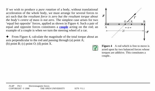
Figure 44A rod which is free to move isacted upon by two balanced forces whosetorques are additive. This constitutes acouple..
If we wish to produce a pure rotation of a body, without translationalacceleration of the whole body, we must arrange for several forces toact such that the resultant force is zero but the resultant torque aboutthe body’s centre of mass is not zero. The simplest case arises for two‘equal but opposite’ forces, applied as shown in Figure 4. Such a pair ofequal and opposite forces constitutes a couple acting on the rod; anexample of a couple is when we turn the steering wheel of a car.
✦ From Figure 4, calculate the magnitude of the total torque about anaxis perpendicular to the rod and passing through (a) point A; (b) point B; (c) point O; (d) point X.

FLAP P4.3 Electromagnetic forcesCOPYRIGHT © 1998 THE OPEN UNIVERSITY S570 V1.1
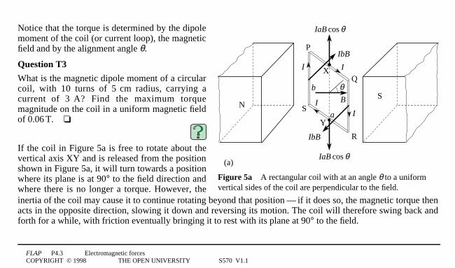
P
IaB cos θ
IbB
Q
R
S
b
B
θ
Y
IaB cos θ
IbB
II
X I
SN
(a)
a
I
Figure 5a4A rectangular coil with at an angle θ to a uniformmagnetic field.
We will now consider the forces produced by amagnetic field on the rectangular coil PQRS, ofdimensions a and b, shown in Figure 5a. The coilcarries a current I , and its instantaneousorientation may be described by the angle θbetween the magnetic field B and a ‘normal’drawn perpendicular to the plane of the coil. Thesections SP and QR of the loop (current at 90° tothe field) will each experience a magnetic force ofmagnitude IbB, directed as shown. The sectionsPQ and RS of the loop (current at (90° − θ ) to thefield) will each experience a magnetic force ofmagnitude IaB1cos1θ, directed vertically, as shown.
FLAP P4.3 Electromagnetic forcesCOPYRIGHT © 1998 THE OPEN UNIVERSITY S570 V1.1
IbB
N S
P
a sin θ
θ
Q90° – θa
(b)
IbB
θ B
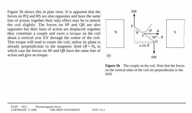
Figure 5b4The couple on the coil. Note that the forceson the vertical sides of the coil are perpendicular to thefield.
Figure 5b shows this in plan view. It is apparent that theforces on PQ and RS are also opposites and have the sameline of action; together their only effect may be to stretchthe coil slightly. The forces on SP and QR are alsoopposites but their lines of action are displaced; togetherthey constitute a couple and exert a torque on the coilabout a vertical axis XY through the centre of the coil.This torque will tend to rotate the coil, unless its plane isalready perpendicular to the magnetic field (θ = 0), inwhich case the forces on SP and QR have the same line ofaction and give no torque.
FLAP P4.3 Electromagnetic forcesCOPYRIGHT © 1998 THE OPEN UNIVERSITY S570 V1.1
IbB
N S
P
a sin θ
θ
Q90° – θa
(b)
IbB
θ B
Figure 5b4The couple on the coil. Note that the forceson the vertical sides of the coil are perpendicular to thefield.
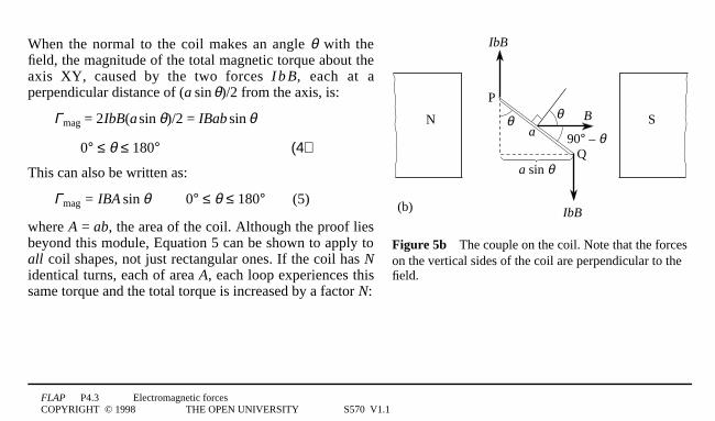
When the normal to the coil makes an angle θ with thefield, the magnitude of the total magnetic torque about theaxis XY, caused by the two forces I b B, each at aperpendicular distance of (a1sin1θ)/2 from the axis, is:
Γmag = 2IbB(a1sin1θ)/2 = IBab1sin1θ
0° ≤ θ ≤ 180° (4)
This can also be written as:
Γmag = IBA1sin1θ 0° ≤ θ ≤ 180° (5)
where A = ab, the area of the coil. Although the proof liesbeyond this module, Equation 5 can be shown to apply toall coil shapes, not just rectangular ones. If the coil has Nidentical turns, each of area A, each loop experiences thissame torque and the total torque is increased by a factor N:
FLAP P4.3 Electromagnetic forcesCOPYRIGHT © 1998 THE OPEN UNIVERSITY S570 V1.1
IbB
N S
P
a sin θ
θ
Q90° – θa
(b)
IbB
θ B
Figure 5b4The couple on the coil. Note that the forceson the vertical sides of the coil are perpendicular to thefield.
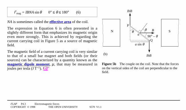
Γmag = IBNA1sin1θ 0° ≤ θ ≤ 180° (6)
NA is sometimes called the effective area of the coil.
The expression in Equation 6 is often presented in aslightly different form that emphasizes its magnetic origineven more strongly. This is achieved by regarding thecurrent carrying coil in Figure 5 as a source of magneticfield.
The magnetic field of a current carrying coil is very similarto that of a small bar magnet and both fields (or theirsources) can be characterized by a quantity known as themagnetic dipole moment, µ, that may be measured injoules per tesla (J1T0−1). ☞
FLAP P4.3 Electromagnetic forcesCOPYRIGHT © 1998 THE OPEN UNIVERSITY S570 V1.1
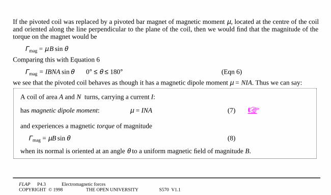
If the pivoted coil was replaced by a pivoted bar magnet of magnetic moment µ, located at the centre of the coiland oriented along the line perpendicular to the plane of the coil, then we would find that the magnitude of thetorque on the magnet would be
Γmag = µ1B1sin1θComparing this with Equation 6
Γmag = IBNA1sin1θ 0° ≤ θ ≤ 180° (Eqn 6)
we see that the pivoted coil behaves as though it has a magnetic dipole moment µ = NIA. Thus we can say:
A coil of area A and N turns, carrying a current I:
has magnetic dipole moment: µ = INA (7) ☞
and experiences a magnetic torque of magnitude
Γmag = µB1sin1θ (8)
when its normal is oriented at an angle θ to a uniform magnetic field of magnitude B.
FLAP P4.3 Electromagnetic forcesCOPYRIGHT © 1998 THE OPEN UNIVERSITY S570 V1.1
P
IaB cos θ
IbB
Q
R
S
b
B
θ
Y
IaB cos θ
IbB
II
X I
SN
(a)
a
I
Figure 5a4A rectangular coil with at an angle θ to a uniformvertical sides of the coil are perpendicular to the field.
Notice that the torque is determined by the dipolemoment of the coil (or current loop), the magneticfield and by the alignment angle θ.
Question T3
What is the magnetic dipole moment of a circularcoil, with 10 turns of 511cm radius, carrying acurrent of 311A? Find the maximum torquemagnitude on the coil in a uniform magnetic fieldof 0.061T.4❏
If the coil in Figure 5a is free to rotate about thevertical axis XY and is released from the positionshown in Figure 5a, it will turn towards a positionwhere its plane is at 90° to the field direction andwhere there is no longer a torque. However, theinertia of the coil may cause it to continue rotating beyond that position1—1if it does so, the magnetic torque thenacts in the opposite direction, slowing it down and reversing its motion. The coil will therefore swing back andforth for a while, with friction eventually bringing it to rest with its plane at 90° to the field.
FLAP P4.3 Electromagnetic forcesCOPYRIGHT © 1998 THE OPEN UNIVERSITY S570 V1.1
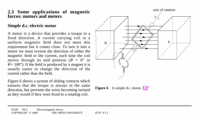
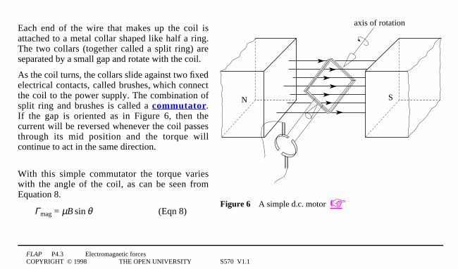
SN
axis of rotation
Figure 64A simple d.c. motor. ☞
2.3 Some applications of magneticforces: motors and meters
Simple d.c. electric motor
A motor is a device that provides a torque in afixed direction. A current carrying coil in auniform magnetic field does not meet thisrequirement but it comes close. To turn it into amotor we must reverse the direction of either themagnetic field or the current, each time the coilmoves through its mid position (θ = 0° orθ = 180°). If the field is produced by a magnet it isusually easier to change the direction of thecurrent rather than the field.
Figure 6 shows a system of sliding contacts whichensures that the torque is always in the samedirection, but prevents the wires becoming twistedas they would if they were fixed to a rotating coil.
FLAP P4.3 Electromagnetic forcesCOPYRIGHT © 1998 THE OPEN UNIVERSITY S570 V1.1
SN
axis of rotation
Figure 64A simple d.c. motor. ☞
Each end of the wire that makes up the coil isattached to a metal collar shaped like half a ring.The two collars (together called a split ring) areseparated by a small gap and rotate with the coil.
As the coil turns, the collars slide against two fixedelectrical contacts, called brushes, which connectthe coil to the power supply. The combination ofsplit ring and brushes is called a commutator.If the gap is oriented as in Figure 6, then thecurrent will be reversed whenever the coil passesthrough its mid position and the torque willcontinue to act in the same direction.
With this simple commutator the torque varieswith the angle of the coil, as can be seen fromEquation 8.
Γmag = µB1sin1θ (Eqn 8)
FLAP P4.3 Electromagnetic forcesCOPYRIGHT © 1998 THE OPEN UNIVERSITY S570 V1.1
This would be a poor design for an electric motor. A torque which is almost independent of angle may beobtained by having many coils on the same axis, distributed at different angles, with a multi-segmentedcommutator feeding the current to the successive coils, with each coil connected for only a small part of therotation.
Question T4
Sketch a graph to show how the magnitude of the magnetic torque in a single-coil d.c. motor changes as the coilrotates.4❏
FLAP P4.3 Electromagnetic forcesCOPYRIGHT © 1998 THE OPEN UNIVERSITY S570 V1.1
N S
axis ofrotation
A
B
brushcontacts
slip ring
directionof rotation
externalcircuit
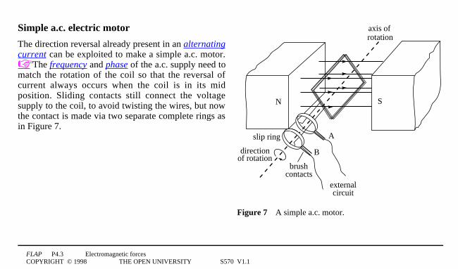
Figure 74A simple a.c. motor.
Simple a.c. electric motor
The direction reversal already present in an alternatingcurrent can be exploited to make a simple a.c. motor.☞ The frequency and phase of the a.c. supply need tomatch the rotation of the coil so that the reversal ofcurrent always occurs when the coil is in its midposition. Sliding contacts still connect the voltagesupply to the coil, to avoid twisting the wires, but nowthe contact is made via two separate complete rings asin Figure 7.

FLAP P4.3 Electromagnetic forcesCOPYRIGHT © 1998 THE OPEN UNIVERSITY S570 V1.1
pointer
scale
magnet
spring
w
l
coil
magneticfield
ironcylinder
NSN
Figure 84A moving-coil galvanometer.
Moving-coilgalvanometer
Figure 8 shows a moving-coilgalvanometer (MCG), withwhich currents or voltagesmay be measured. The set-upis essentially that of Figure 5,but with some modifications.Τhere is a pointer attached tothe coil which is wound on asoft iron core ☞ and isattached to a flat spiralspring, providing an opposite torque on the coil. The poles of the magnet are hollowed out so that a uniformradially-directed field is created within the gap and across the coil. These modifications are designed to producea measurable angular deflection of the coil which is linearly proportional to the current in the coil.

FLAP P4.3 Electromagnetic forcesCOPYRIGHT © 1998 THE OPEN UNIVERSITY S570 V1.1
Suppose the spring holds the coil with the pointer at the centre of the scale when there is no current. A current inthe coil will produce a torque so that the coil turns. As it turns it will meet an increasing opposing torque fromthe spring. The spring is chosen so that if it is twisted through a (positive) angle α , an opposing torque Gs, ofmagnitude Cα, (i.e. linear in α) is produced ☞; so
Γs = Cα (9)
At equilibrium, Gs is equal and opposite to the magnetic torque Gmag, implying that their magnitudes are equal.
Equation 6 shows that the magnetic torque is directly proportional to the current and also depends on the anglebetween the coil and the magnetic field. With the uniform radially-directed field the plane of the coil lies alongthe field direction (θ = 90°), irrespective of the angle α through which the coil has turned, so the magnetic forceon each side of the coil is constant and always at right angles to the plane of the coil. Equation 6
Γmag = IBNA1sin1θ 0° ≤ θ ≤ 180° (Eqn 6)
then gives:
Γmag = IBNA (10)
✦ Use Equations 9 and 10 to derive the equilibrium condition when a current I flows in the coil.
FLAP P4.3 Electromagnetic forcesCOPYRIGHT © 1998 THE OPEN UNIVERSITY S570 V1.1
Question T5
A galvanometer coil has 20 rectangular turns, each 11cm by 21cm. It can rotate about a central vertical axis in aradial magnetic field of 0.0151T, and a spring with C = 1.2 × 10 0–41N1m1rad–1 resists its rotation.What current will produce a deflection of 22°?4❏
FLAP P4.3 Electromagnetic forcesCOPYRIGHT © 1998 THE OPEN UNIVERSITY S570 V1.1
wire 1
wire 2
d
I1
I2
B1(r)
B2(r)
Figure 94The magnetic fields producedby the currents in two long straightparallel wires.
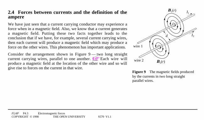
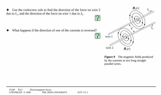
2.4 Forces between currents and the definition of theampereWe have just seen that a current carrying conductor may experience aforce when in a magnetic field. Also, we know that a current generatesa magnetic field. Putting these two facts together leads to theconclusion that if we have, for example, several current carrying wires,then each current will produce a magnetic field which may produce aforce on the other wires. This phenomenon has important applications.
Consider the arrangement shown in Figure 91— 1two long straightcurrent carrying wires, parallel to one another. ☞ Each wire willproduce a magnetic field at the location of the other wire and so willgive rise to forces on the current in that wire.
FLAP P4.3 Electromagnetic forcesCOPYRIGHT © 1998 THE OPEN UNIVERSITY S570 V1.1
wire 1
wire 2
d
I1
I2
B1(r)
B2(r)
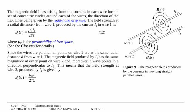
Figure 94The magnetic fields producedby the currents in two long straightparallel wires.
The magnetic field lines arising from the currents in each wire form aset of concentric circles around each of the wires, the direction of thefield lines being given by the right-hand grip rule. The field strength ata radial distance r from wire 1, produced by the current I1 in wire 1 is:
B1(r) = µ0 I1
2πr(12)
where µ0 is the permeability of free space. (See the Glossary for details.)
Since the wires are parallel, all points on wire 2 are at the same radialdistance d from wire 1. The magnetic field produced by I1 has the samemagnitude at every point on wire 2 and, moreover, always points in adirection perpendicular to I2. This means that the field strength atwire 2, produced by I1 is given by
B1(d) = µ0 I1
2πd
FLAP P4.3 Electromagnetic forcesCOPYRIGHT © 1998 THE OPEN UNIVERSITY S570 V1.1
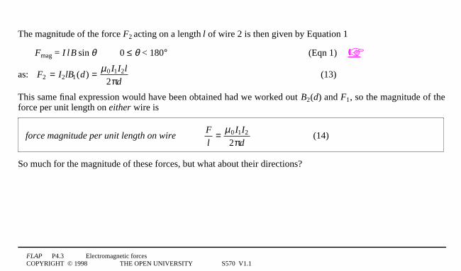
The magnitude of the force F2 acting on a length l of wire 2 is then given by Equation 1
Fmag = I1l1B1sin1θ 0 ≤ θ < 180° (Eqn 1) ☞
as: F2 = I2lB1(d) = µ0 I1I2l
2πd(13)
This same final expression would have been obtained had we worked out B2(d) and F1, so the magnitude of theforce per unit length on either wire is
force magnitude per unit length on wireF
l= µ0 I1I2
2πd(14)
So much for the magnitude of these forces, but what about their directions?
FLAP P4.3 Electromagnetic forcesCOPYRIGHT © 1998 THE OPEN UNIVERSITY S570 V1.1
wire 1
wire 2
d
I1
I2
B1(r)
B2(r)
Figure 94The magnetic fields producedby the currents in two long straightparallel wires.
✦ Use the corkscrew rule to find the direction of the force on wire 2due to I1, and the direction of the force on wire 1 due to I2.
✦ What happens if the direction of one of the currents is reversed?
FLAP P4.3 Electromagnetic forcesCOPYRIGHT © 1998 THE OPEN UNIVERSITY S570 V1.1
All this may be summarized by the rule;
Like currents attract, unlike currents repel. ☞
Question T6
A large current flows in a circular path within an ionized gas (called a plasma). Explain whether such a currentloop could be stable or whether there would be a tendency for it to collapse inwards or expand outwards, due tothe mutual magnetic forces.4❏
Equation 14
force magnitude per unit length on wireF
l= µ0 I1I2
2πd(Eqn 14)
provides a definition of the basic SI electrical unit in terms of the basic mechanical units of force and distance.This basic electrical unit is that of electric current and is called the ampere. ☞
FLAP P4.3 Electromagnetic forcesCOPYRIGHT © 1998 THE OPEN UNIVERSITY S570 V1.1
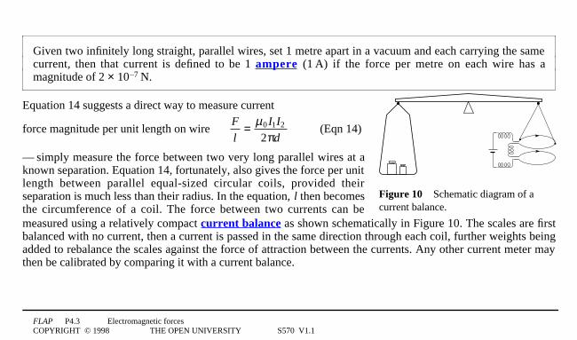
Given two infinitely long straight, parallel wires, set 1 metre apart in a vacuum and each carrying the samecurrent, then that current is defined to be 1 ampere (11A) if the force per metre on each wire has amagnitude of 2 × 100–71N.
Figure 104Schematic diagram of acurrent balance.
Equation 14 suggests a direct way to measure current1
force magnitude per unit length on wireF
l= µ0 I1I2
2πd(Eqn 14)
—1simply measure the force between two very long parallel wires at aknown separation. Equation 14, fortunately, also gives the force per unitlength between parallel equal-sized circular coils, provided theirseparation is much less than their radius. In the equation, l then becomesthe circumference of a coil. The force between two currents can bemeasured using a relatively compact current balance as shown schematically in Figure 10. The scales are firstbalanced with no current, then a current is passed in the same direction through each coil, further weights beingadded to rebalance the scales against the force of attraction between the currents. Any other current meter maythen be calibrated by comparing it with a current balance.
FLAP P4.3 Electromagnetic forcesCOPYRIGHT © 1998 THE OPEN UNIVERSITY S570 V1.1
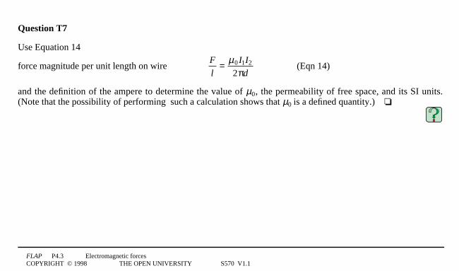
Question T7
Use Equation 14
force magnitude per unit length on wireF
l= µ0 I1I2
2πd(Eqn 14)
and the definition of the ampere to determine the value of µ0, the permeability of free space, and its SI units.(Note that the possibility of performing such a calculation shows that µ0 is a defined quantity.)4❏

FLAP P4.3 Electromagnetic forcesCOPYRIGHT © 1998 THE OPEN UNIVERSITY S570 V1.1
current I
N
S
F1mag
wire
Blines of magnetic field
electrons
θ
Figure 114Electrons travelling through awire in a magnetic field and experiencinga magnetic force.
3 Magnetic forces on a moving chargedparticleIn Section 2 we considered magnetic forces on currents, i.e. on largenumbers of moving charged particles. We now turn our attention to themagnetic force on an individual moving charged particle. We will firstconsider an electron moving in a wire within a magnetic field and thengeneralize to a charged particle whose motion is unconstrained.
3.1 The magnetic force on an electron in a wireFigure 11 shows a straight wire, carrying a current I, at an angle θ to auniform magnetic field B. The magnitude Fmag of the magnetic forceon a length l of the wire is
Fmag = I0l0B1sin1θ (Eqn 1)
From our discussions in Section 2 and knowing that current consists ofa movement of charged particles, we can deduce some importantcharacteristics of the magnetic force on a single charged particle ☞:
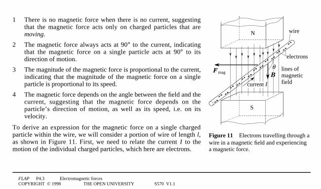
FLAP P4.3 Electromagnetic forcesCOPYRIGHT © 1998 THE OPEN UNIVERSITY S570 V1.1
current I
N
S
F1mag
wire
Blines of magnetic field
electrons
θ
Figure 114Electrons travelling through awire in a magnetic field and experiencinga magnetic force.
1 There is no magnetic force when there is no current, suggestingthat the magnetic force acts only on charged particles that aremoving.
2 The magnetic force always acts at 90° to the current, indicatingthat the magnetic force on a single particle acts at 90° to itsdirection of motion.
3 The magnitude of the magnetic force is proportional to the current,indicating that the magnitude of the magnetic force on a singleparticle is proportional to its speed.
4 The magnetic force depends on the angle between the field and thecurrent, suggesting that the magnetic force depends on theparticle’s direction of motion, as well as its speed, i.e. on itsvelocity.
To derive an expression for the magnetic force on a single chargedparticle within the wire, we will consider a portion of wire of length l,as shown in Figure 11. First, we need to relate the current I to themotion of the individual charged particles, which here are electrons.
FLAP P4.3 Electromagnetic forcesCOPYRIGHT © 1998 THE OPEN UNIVERSITY S570 V1.1
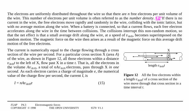
The electrons are uniformly distributed throughout the wire so that there are n free electrons per unit volume ofthe wire. This number of electrons per unit volume is often referred to as the number density. ☞ If there is nocurrent in the wire, the free electrons move rapidly and randomly in the wire, colliding with the ionic lattice, butwith no average motion along the wire. When a battery is connected, so that a current flows, each free electronaccelerates along the wire in the time between collisions. The collisions interrupt this non-random motion, sothat the net effect is that a small average drift along the wire, at a speed of vdrift, becomes superimposed on therandom motion. The magnetic force on the wire then arises as a result of the magnetic force on this average driftmotion of the free electrons.
X
A
length vdriftt
Figure 124All the free electrons withina length vdriftt of a cross section of thewire move through that cross section in atime interval t.
The current is numerically equal to the charge flowing through a crosssection of the wire per second. For a particular cross section X (area A)of the wire, as shown in Figure 12, all those electrons within a distancevdriftt to the left of X, flow past X in a time t. That is, all the electrons inthe volume Avdrift, a total of nAvdrift electrons, pass through X in onesecond. As each electron carries a charge of magnitude e, the numericalvalue of the charge flow per second, the current I, is
I = nAvdrifte (15)
FLAP P4.3 Electromagnetic forcesCOPYRIGHT © 1998 THE OPEN UNIVERSITY S570 V1.1
The magnitude of the magnetic force on a length l of the wire is therefore:
Fmag = nAvdriftelB1sin1θ (16)
As our segment of wire has a volume A0l, the number of free electrons in it is nAl, and we can divide Equation 16by nAl to obtain:
The magnitude of the magnetic force on a single electron moving with speed vdrift at angle θ to a magneticfield of magnitude B:
Fmag = evdriftB1sin1θ (17)
Question T8
Why is it, that in calculating the magnetic force on the electrons which make up the current in the wire, we canignore the very large random velocities which these electrons may have?4❏
Question T9
The number density of free electrons in copper is 8.5 × 10281m–3. Find the drift speed of the electrons when thereis a current of 0.21A in a copper wire of diameter 2 mm.4❏
FLAP P4.3 Electromagnetic forcesCOPYRIGHT © 1998 THE OPEN UNIVERSITY S570 V1.1
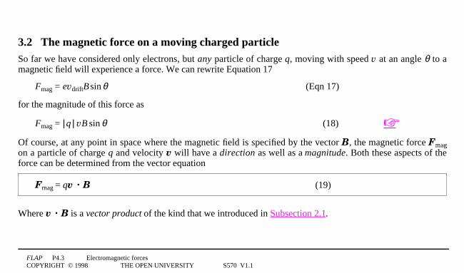
3.2 The magnetic force on a moving charged particleSo far we have considered only electrons, but any particle of charge q, moving with speed v at an angle θ to amagnetic field will experience a force. We can rewrite Equation 17
Fmag = evdriftB1sin1θ (Eqn 17)
for the magnitude of this force as
Fmag = |1q1| vB1sin1θ (18) ☞
Of course, at any point in space where the magnetic field is specified by the vector B, the magnetic force Fmagon a particle of charge q and velocity v will have a direction as well as a magnitude. Both these aspects of theforce can be determined from the vector equation
Fmag = qv · B (19)
Where v · B is a vector product of the kind that we introduced in Subsection 2.1.
FLAP P4.3 Electromagnetic forcesCOPYRIGHT © 1998 THE OPEN UNIVERSITY S570 V1.1
You will recall that writing such a relationship
Fmag = qv · B (Eqn 19)
implies that
1 Fmag = |1Fmag1| = |1q1|0v0B1sin1θ (Eqn 18)
where θ is the smaller angle between v and B.
2 The direction of F is given by the corkscrew rule (or, equivalently, the right-hand rule) as the direction inwhich the tip of a corkscrew would advance if its handle were turned from the direction of the first vector(v) to the direction of the second vector (B) through the smaller angle (θ) between them.
Equation 19 is a very important equation. It applies just as well in a non-uniform magnetic field where B variesfrom point to point (and is usually written B(r)) as it does in a uniform field where the magnitude and directionof B are the same at all points.
You should certainly try to remember Equation 19, but when using it you should also remember that the sign ofq is important, and so is the order of the vectors in the cross product (v · B not B · v). If you use the wrongsign for q, or if you reverse the order of v and B you will obtain the wrong sign (and hence the wrong direction)for Fmag. In practice, when using Equation 19, it is generally best to first apply the corkscrew (or right-hand) ruleto v · B to determine its direction, and then recognize this as either parallel or antiparallel to Fmag, according towhether q is positive or negative. Some immediate practice in using Equation 19 is in order.
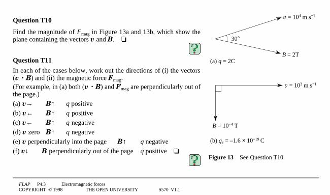
FLAP P4.3 Electromagnetic forcesCOPYRIGHT © 1998 THE OPEN UNIVERSITY S570 V1.1
30°
(a) q = 2C
v = 104 m s−1
B = 2T
B = 10−4 T
(b) qz = –1.6 × 10⁻¹⁹ C
v = 103 m s−1
Figure 134See Question T10.
Question T10
Find the magnitude of Fmag in Figure 13a and 13b, which show theplane containing the vectors v and B.4❏
Question T11
In each of the cases below, work out the directions of (i) the vectors(v · B) and (ii) the magnetic force Fmag.(For example, in (a) both (v · B) and Fmag are perpendicularly out ofthe page.)
(a) v→ B↑ q positive
(b) v← B↑ q positive
(c) v← B↑ q negative
(d) v zero B↑ q negative
(e) v perpendicularly into the page B↑ q negative
(f) v↓ B perpendicularly out of the page q positive4❏
FLAP P4.3 Electromagnetic forcesCOPYRIGHT © 1998 THE OPEN UNIVERSITY S570 V1.1
y
x
θv
B
zv⊥ (v⊥ = v sin θ)
v (v = v cos θ)
Figure 144The component vectors ofvelocity parallel and perpendicular to themagnetic field B are v|1| and v⊥ . Note
that v|1 | = |1v|1 |11| and v⊥ = |1v⊥ 1|.
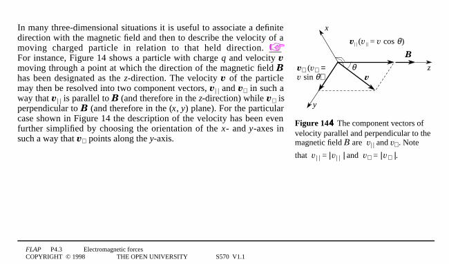
In many three-dimensional situations it is useful to associate a definitedirection with the magnetic field and then to describe the velocity of amoving charged particle in relation to that held direction. ☞For instance, Figure 14 shows a particle with charge q and velocity vmoving through a point at which the direction of the magnetic field Bhas been designated as the z-direction. The velocity v of the particlemay then be resolved into two component vectors, v|1 | and v⊥ in such away that v|1 | is parallel to B (and therefore in the z-direction) while v⊥ isperpendicular to B (and therefore in the (x, y) plane). For the particularcase shown in Figure 14 the description of the velocity has been evenfurther simplified by choosing the orientation of the x- and y-axes insuch a way that v⊥ points along the y-axis.
FLAP P4.3 Electromagnetic forcesCOPYRIGHT © 1998 THE OPEN UNIVERSITY S570 V1.1
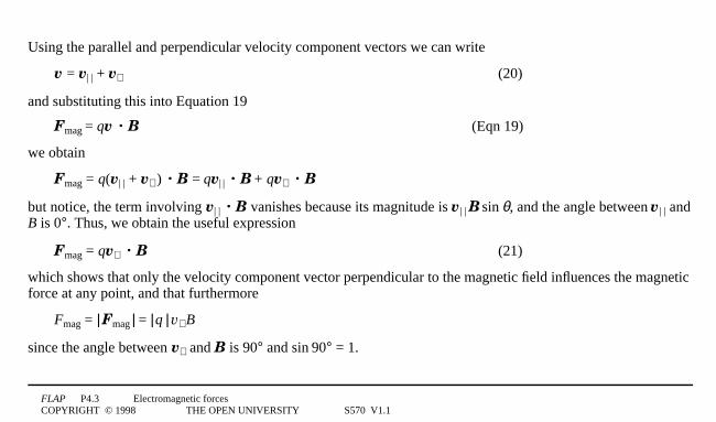
Using the parallel and perpendicular velocity component vectors we can write
v = v|1 | + v⊥ (20)
and substituting this into Equation 19
Fmag = qv · B (Eqn 19)
we obtain
Fmag = q(v|1 | + v⊥ 0) · B = qv|1| · B + qv⊥ · B
but notice, the term involving v|1 | · B vanishes because its magnitude is v |1 |1B1sin1θ, and the angle between v |1 | andB is 0°. Thus, we obtain the useful expression
Fmag = qv⊥ · B (21)
which shows that only the velocity component vector perpendicular to the magnetic field influences the magneticforce at any point, and that furthermore
Fmag = |1Fmag1| = |1q1|1v⊥ B
since the angle between v⊥ and B is 90° and sin190° = 1.

FLAP P4.3 Electromagnetic forcesCOPYRIGHT © 1998 THE OPEN UNIVERSITY S570 V1.1
Determining the magnetic field at a pointEquations 19 (and 21)
Fmag = qv · B (Eqn 19)
Fmag = qv⊥ · B (Eqn 21)
provide a means of determining the magnitude and direction of any magnetic field at a point, and of deriving itsunits. For example, from Equation 21, when a particle of charge 11C moves at a speed of 11m1s–1 perpendicularlyto a magnetic field of strength 11T, it experiences a magnetic force of magnitude 11N. More generally, if aparticle of charge q experiences a magnetic force F1 when it travels through a point with velocity v1, and amagnetic force F2 when it travels through the same point with a velocity v2 that is perpendicular to v1 then itcan be shown from Equation 19 that the magnetic field at that point is
B = 1
q
F1 ¥¥ v1
v12
+ 1q
(F2 ¥¥ v2 )⋅v1
v12v2
2
v1
where the second term on the right describes the component of B in the direction of v1, and the first termdescribes the component of B perpendicular to v1. ☞✦ Use Equation 21 to derive the SI units of B, and show that they are equivalent to N1A−11m−1, as derived inSubsection 2.1.
FLAP P4.3 Electromagnetic forcesCOPYRIGHT © 1998 THE OPEN UNIVERSITY S570 V1.1
3.3 Motion of a charge along or perpendicular to a uniform magnetic fieldBefore we consider the general motion of a charge in a magnetic field we will start by taking the special caseswhere the charge is moving either parallel to the field or perpendicular to the field.
Motion parallel to the field
✦ Describe what happens if the motion of a moving charge is parallel to the field or opposite (antiparallel) tothe field (i.e. v = v⊥ , with v|1 | = 0).
FLAP P4.3 Electromagnetic forcesCOPYRIGHT © 1998 THE OPEN UNIVERSITY S570 V1.1
v
B
q
Figure 154A uniform magnetic fielddirected into the page. v⊥ is the initialvelocity vector of a particle of charge qmoving perpendicular to the field, in theplane of the page.
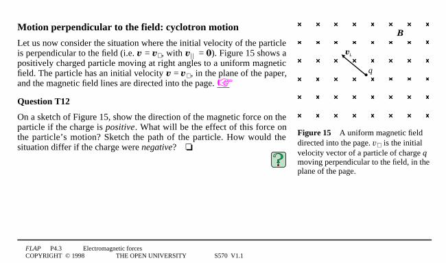
Motion perpendicular to the field: cyclotron motion
Let us now consider the situation where the initial velocity of the particleis perpendicular to the field (i.e. v = v⊥ , with v|1| = 0). Figure 15 shows apositively charged particle moving at right angles to a uniform magneticfield. The particle has an initial velocity v = v⊥ , in the plane of the paper,and the magnetic field lines are directed into the page. ☞
Question T12
On a sketch of Figure 15, show the direction of the magnetic force on theparticle if the charge is positive. What will be the effect of this force onthe particle’s motion? Sketch the path of the particle. How would thesituation differ if the charge were negative?4❏
FLAP P4.3 Electromagnetic forcesCOPYRIGHT © 1998 THE OPEN UNIVERSITY S570 V1.1
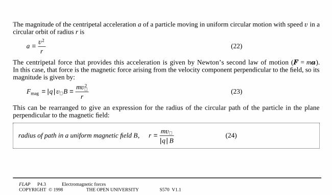
The magnitude of the centripetal acceleration a of a particle moving in uniform circular motion with speed v in acircular orbit of radius r is
a = v2
r(22)
The centripetal force that provides this acceleration is given by Newton’s second law of motion (F = ma).In this case, that force is the magnetic force arising from the velocity component perpendicular to the field, so itsmagnitude is given by:
Fmag = |q | v⊥ B = mv⊥
2
r(23)
This can be rearranged to give an expression for the radius of the circular path of the particle in the planeperpendicular to the magnetic field:
radius of path in a uniform magnetic field B, r = mv⊥
|q | B(24)
FLAP P4.3 Electromagnetic forcesCOPYRIGHT © 1998 THE OPEN UNIVERSITY S570 V1.1
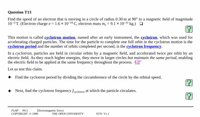
Question T13
Find the speed of an electron that is moving in a circle of radius 0.301m at 90° to a magnetic field of magnitude100−31T. (Electron charge e = 1.6 × 10−191C, electron mass me = 9.1 × 10−311kg.)4❏
This motion is called cyclotron motion, named after an early instrument, the cyclotron, which was used foraccelerating charged particles. The time for the particle to complete one full orbit in the cyclotron motion is thecyclotron period and the number of orbits completed per second, is the cyclotron frequency.
In a cyclotron, particles are held in circular orbits by a magnetic field, and accelerated twice per orbit by anelectric field. As they reach higher energies, they move in larger circles but maintain the same period, enablingthe electric field to be applied at the same frequency throughout the process. ☞
Let us test this claim.
✦ Find the cyclotron period by dividing the circumference of the circle by the orbital speed.
✦ Next, find the cyclotron frequency fcyclotron at which the particle circulates.
FLAP P4.3 Electromagnetic forcesCOPYRIGHT © 1998 THE OPEN UNIVERSITY S570 V1.1
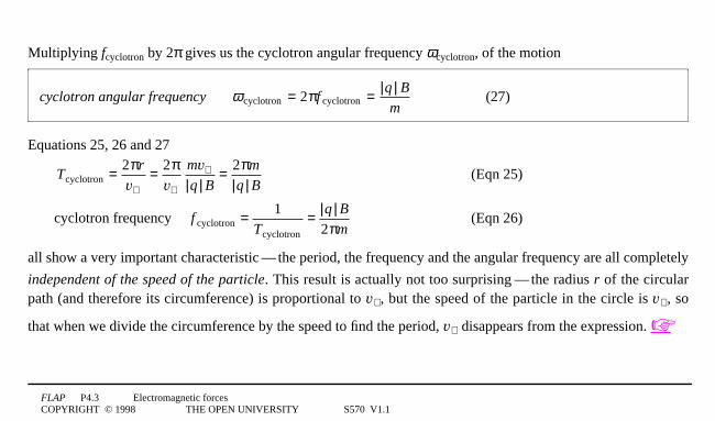
Multiplying fcyclotron by 2π gives us the cyclotron angular frequency ωcyclotron, of the motion
cyclotron angular frequency ω cyclotron = 2πf cyclotron = |q | B
m(27)
Equations 25, 26 and 27
Tcyclotron = 2πr
v⊥= 2π
v⊥
mv⊥
|q | B= 2πm
|q | B(Eqn 25)
cyclotron frequency f cyclotron = 1Tcyclotron
= |q | B
2πm (Eqn 26)
all show a very important characteristic1—1the period, the frequency and the angular frequency are all completely
independent of the speed of the particle. This result is actually not too surprising1—1the radius r of the circularpath (and therefore its circumference) is proportional to v⊥ , but the speed of the particle in the circle is v⊥ , so
that when we divide the circumference by the speed to find the period, v⊥ disappears from the expression. ☞

FLAP P4.3 Electromagnetic forcesCOPYRIGHT © 1998 THE OPEN UNIVERSITY S570 V1.1
The factors which determine the period of an orbit are the mass-to-charge ratio (m/q) and the magnetic field.Suppose there are lots of particles, all with the same value of m/q, moving in a given magnetic field. They maybe travelling with many different speeds and in many different directions1—1those with very small v⊥ will bemoving in small circles, the fast ones in large circles1—1but all take exactly the same time to complete an orbit!
One final general point is interesting. Since the magnetic force acts always at right angles to the velocity, itchanges only the direction, not the speed, of the particle, which therefore travels in a circular path at constantspeed and with constant energy. A steady magnetic field can never increase the kinetic energy of a chargedparticle1—1an electric field is needed to do this, as we said earlier.
Question T14
(a) Verify that Equation 26
cyclotron frequency f cyclotron = 1Tcyclotron
= |q | B
2πm (Eqn 26)
gives suitable units for frequency. (b) Find the cyclotron frequency of an electron moving in a field of0.051T.4❏
FLAP P4.3 Electromagnetic forcesCOPYRIGHT © 1998 THE OPEN UNIVERSITY S570 V1.1
v
vv
B
x
z
y
Figure 164The helical path of a charged particle in auniform magnetic field.
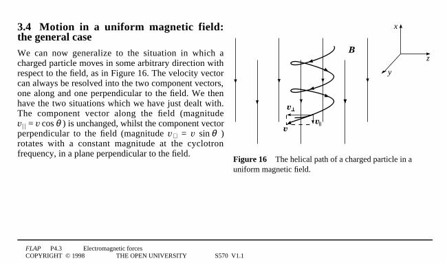
3.4 Motion in a uniform magnetic field:the general caseWe can now generalize to the situation in which acharged particle moves in some arbitrary direction withrespect to the field, as in Figure 16. The velocity vectorcan always be resolved into the two component vectors,one along and one perpendicular to the field. We thenhave the two situations which we have just dealt with.The component vector along the field (magnitudev|1| = v1cos1θ ) is unchanged, whilst the component vectorperpendicular to the field (magnitude v⊥ = v 1sin1θ )rotates with a constant magnitude at the cyclotronfrequency, in a plane perpendicular to the field.
FLAP P4.3 Electromagnetic forcesCOPYRIGHT © 1998 THE OPEN UNIVERSITY S570 V1.1
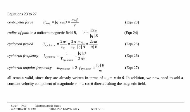
Equations 23 to 27
centripetal force Fmag = |q | v⊥ B = mv⊥
2
r(Eqn 23)
radius of path in a uniform magnetic field B, r = mv⊥
|q | B(Eqn 24)
cyclotron period Tcyclotron = 2πr
v⊥= 2π
v⊥
mv⊥
|q | B= 2πm
|q | B(Eqn 25)
cyclotron frequency f cyclotron = 1Tcyclotron
= |q | B
2πm (Eqn 26)
cyclotron angular frequency ω cyclotron = 2πf cyclotron = |q | B
m(Eqn 27)
all remain valid, since they are already written in terms of v⊥ = v1sin1θ. In addition, we now need to add a
constant velocity component of magnitude v|1| = v1cos1θ directed along the magnetic field.
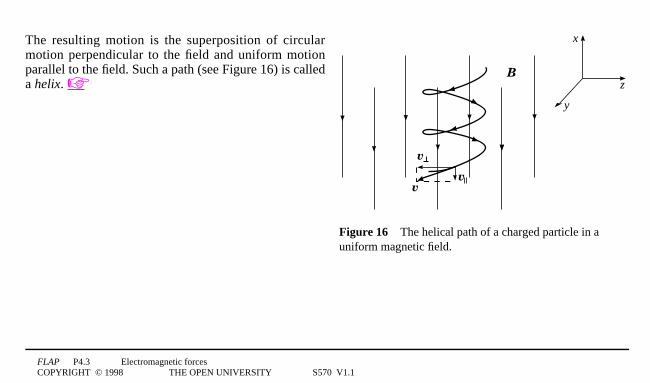
FLAP P4.3 Electromagnetic forcesCOPYRIGHT © 1998 THE OPEN UNIVERSITY S570 V1.1
v
vv
B
x
z
y
Figure 164The helical path of a charged particle in auniform magnetic field.
The resulting motion is the superposition of circularmotion perpendicular to the field and uniform motionparallel to the field. Such a path (see Figure 16) is calleda helix. ☞

FLAP P4.3 Electromagnetic forcesCOPYRIGHT © 1998 THE OPEN UNIVERSITY S570 V1.1
positiveplate
negativeplate
charge q(at r)
Fel
Figure 174The electric force Fel on acharged particle in the electric fieldbetween two oppositely charged plates.
4 The electromagnetic forceCharged particles may be influenced by electric forces and by a magneticforces. The difference between these is that for a magnetic force to act thecharge must be moving, but the electric force is independent of themotion. ☞ The total force due to a combination of electric and magneticfields is called the electromagnetic force; it is the sum of an electric anda magnetic force. It is this force which we will now describe.
4.1 The Lorentz force lawThere are many physical situations (e.g. in an oscilloscope or a televisiontube) in which a particle is acted upon simultaneously by electric andmagnetic forces. Figure 17 shows a charged particle in an electric field.If the charge q is at a point where the electric field is E, the electric forceFel on it is given by:
Fel = qE (28) ☞
Thus the direction of the electric force is parallel to the electric field if the charge q is positive, and antiparallelif it is negative.
FLAP P4.3 Electromagnetic forcesCOPYRIGHT © 1998 THE OPEN UNIVERSITY S570 V1.1
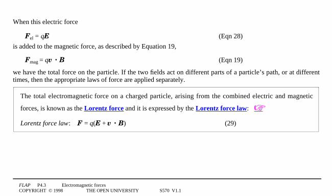
When this electric force
Fel = qE (Eqn 28)
is added to the magnetic force, as described by Equation 19,
Fmag = qv · B (Eqn 19)
we have the total force on the particle. If the two fields act on different parts of a particle’s path, or at differenttimes, then the appropriate laws of force are applied separately.
The total electromagnetic force on a charged particle, arising from the combined electric and magnetic
forces, is known as the Lorentz force and it is expressed by the Lorentz force law: ☞
Lorentz force law: F = q(E + v · B) (29)
FLAP P4.3 Electromagnetic forcesCOPYRIGHT © 1998 THE OPEN UNIVERSITY S570 V1.1
Question T15
At a point in space there is an electric field of 1041V1m–1 in the x-direction and a magnetic field of 5 × 10–31T inthe y-direction. An α-particle ☞ moves in the plane containing E and B, through the point, with a velocity of1061m1s–1, at 45° to both the electric and magnetic fields. What is the net force on the particle?4❏

FLAP P4.3 Electromagnetic forcesCOPYRIGHT © 1998 THE OPEN UNIVERSITY S570 V1.1
5 Some applications of the Lorentz forceThe importance of the Lorentz force law, Equation 29,
Lorentz force law: F = q(E + v · B) (Eqn 29)
cannot be overemphasized. Numerous technological applications and experiments in fundamental science flowfrom it. In this section we will look at just a few of these, beginning with a measurement of the electron’scharge-to-mass ratio.
5.1 Measuring the charge-to-mass ratio of the electronIn Subsection 3.3 (e.g. Equation 24)
radius of path in a uniform magnetic field B, r = mv⊥
|q | B(Eqn 24)
we saw that the path of a particle under the influence of a magnetic force depends on its ratio of charge-to-mass.In 1897 J. J. Thomson announced the results of a series of experiments to measure the charge-to-mass ratio forelectrons ☞.
FLAP P4.3 Electromagnetic forcesCOPYRIGHT © 1998 THE OPEN UNIVERSITY S570 V1.1
coil
plate G
electrode Amagnetic
field
electronbeam
fluorescent screen
plate H
coilelectrode D
electronsource C
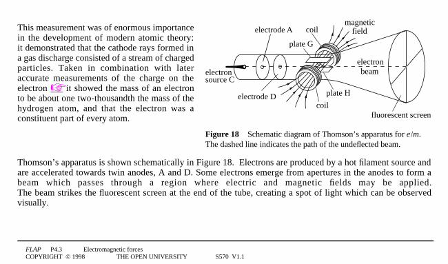
Figure 184Schematic diagram of Thomson’s apparatus for e0/m.The dashed line indicates the path of the undeflected beam.
This measurement was of enormous importancein the development of modern atomic theory:it demonstrated that the cathode rays formed ina gas discharge consisted of a stream of chargedparticles. Taken in combination with lateraccurate measurements of the charge on theelectron ☞ it showed the mass of an electronto be about one two-thousandth the mass of thehydrogen atom, and that the electron was aconstituent part of every atom.
Thomson’s apparatus is shown schematically in Figure 18. Electrons are produced by a hot filament source andare accelerated towards twin anodes, A and D. Some electrons emerge from apertures in the anodes to form abeam which passes through a region where electric and magnetic fields may be applied.The beam strikes the fluorescent screen at the end of the tube, creating a spot of light which can be observedvisually.
FLAP P4.3 Electromagnetic forcesCOPYRIGHT © 1998 THE OPEN UNIVERSITY S570 V1.1
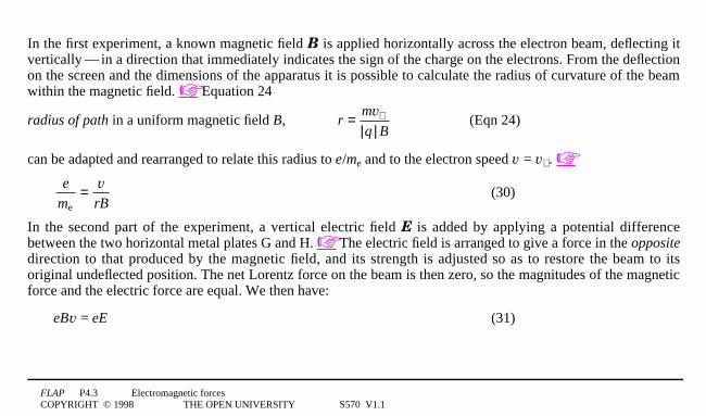
In the first experiment, a known magnetic field B is applied horizontally across the electron beam, deflecting itvertically1—1in a direction that immediately indicates the sign of the charge on the electrons. From the deflectionon the screen and the dimensions of the apparatus it is possible to calculate the radius of curvature of the beamwithin the magnetic field. ☞ Equation 24
radius of path in a uniform magnetic field B, r = mv⊥
|q | B(Eqn 24)
can be adapted and rearranged to relate this radius to e/me and to the electron speed v = v⊥ . ☞
e
me= v
rB(30)
In the second part of the experiment, a vertical electric field E is added by applying a potential differencebetween the two horizontal metal plates G and H. ☞ The electric field is arranged to give a force in the oppositedirection to that produced by the magnetic field, and its strength is adjusted so as to restore the beam to itsoriginal undeflected position. The net Lorentz force on the beam is then zero, so the magnitudes of the magneticforce and the electric force are equal. We then have:
eBv = eE (31)
FLAP P4.3 Electromagnetic forcesCOPYRIGHT © 1998 THE OPEN UNIVERSITY S570 V1.1
or the speed required to give no deflection is:
v = E
B(32) ☞
✦ Use Equations 30 and 32
e
me= v
rB(Eqn 30)
to find an expression for e/me in terms of experimentally-determined quantities.
FLAP P4.3 Electromagnetic forcesCOPYRIGHT © 1998 THE OPEN UNIVERSITY S570 V1.1
5.2 The velocity selector
Question T16
Suppose that in the experimental arrangement described in Subsection 5.1 the beam of particles consists not justof electrons but also neutral atoms and ions of different masses and charges, moving with a range of differentspeeds, but all in the same well-defined direction down the axis. If there were a small aperture on the axis,downstream of the magnetic and electric field region, describe how the beam emerging from this aperture willdiffer from the beam which enters the field region.4❏
As you can see from Question T16, this device could be said to act as a velocity selector for charged particlesand finds important application for this purpose.
FLAP P4.3 Electromagnetic forcesCOPYRIGHT © 1998 THE OPEN UNIVERSITY S570 V1.1
5.3 The mass spectrometerEquation 24
radius of path in a uniform magnetic field B, r = mv⊥
|q | B(Eqn 24)
shows that when a charged particle, such as an ion, moves in a given magnetic field, its trajectory is determinedby its velocity component in the plane perpendicular to the field and by its charge-to-mass ratio. Once the chargeon a particular ion is known, its trajectory in a known magnetic field allows the mass of the ion to be found.The study of ion masses and the associated atomic masses by such methods is called mass spectrometry and theinstruments used are called mass spectrometers. Over the past century, mass spectrometry has made animportant contribution to our understanding of matter on the atomic scale, in establishing atomic masses.It has also provided an important analytical technique for identifying unknown ions by their mass. It has beenused, for example, to determine the composition and origins of meteorites and the ages of archaeologicalspecimens. We will look at two examples of such measurements in a moment, but first we consider the design ofa simple mass spectrometer.
FLAP P4.3 Electromagnetic forcesCOPYRIGHT © 1998 THE OPEN UNIVERSITY S570 V1.1
deflection chamber
V
ion sourceion current
collector plate
S2
S1
S3
B
Figure 194Schematic diagram of a Dempster mass spectrometer.
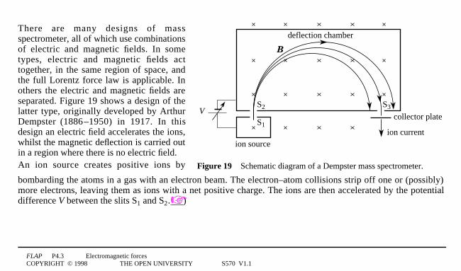
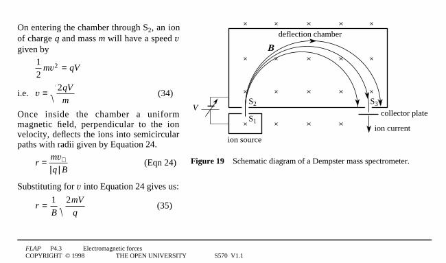
There are many designs of massspectrometer, all of which use combinationsof electric and magnetic fields. In sometypes, electric and magnetic fields acttogether, in the same region of space, andthe full Lorentz force law is applicable. Inothers the electric and magnetic fields areseparated. Figure 19 shows a design of thelatter type, originally developed by ArthurDempster (18860–1950) in 1917. In thisdesign an electric field accelerates the ions,whilst the magnetic deflection is carried outin a region where there is no electric field.An ion source creates positive ions by
bombarding the atoms in a gas with an electron beam. The electron–atom collisions strip off one or (possibly)more electrons, leaving them as ions with a net positive charge. The ions are then accelerated by the potentialdifference V between the slits S1 and S2.☞)
FLAP P4.3 Electromagnetic forcesCOPYRIGHT © 1998 THE OPEN UNIVERSITY S570 V1.1
deflection chamber
V
ion sourceion current
collector plate
S2
S1
S3
B
Figure 194Schematic diagram of a Dempster mass spectrometer.
On entering the chamber through S2, an ionof charge q and mass m will have a speed vgiven by
12
mv2 = qV
i.e. v = 2qV
m(34)
Once inside the chamber a uniformmagnetic field, perpendicular to the ionvelocity, deflects the ions into semicircularpaths with radii given by Equation 24.
r = mv⊥
|q | B(Eqn 24)
Substituting for v into Equation 24 gives us:
r = 1B
2mV
q(35)
FLAP P4.3 Electromagnetic forcesCOPYRIGHT © 1998 THE OPEN UNIVERSITY S570 V1.1
Those ions whose path diameter is equal to the distance from slit S2 to slit S3 can escape from the chamber andarrive at a collector plate, and the ion current produced at the plate is a measure of the rate of arrival of thoseparticular ions.
The mass spectrometer can be adjusted to detect each ion in turn by changing the value of the accelerator voltageV, with B held fixed. Often this adjustment can be done automatically, to produce a mass scan across the wholemass range accessible to the instrument. The relative ion currents then give the relative concentrations of theions in the sample.
Having discussed the theory, we will look briefly at two examples of the use of mass spectrometry.
Living biological material contains a mixture of the isotopes of carbon: mainly 12C with a small amount ofradioactive 14C. ☞ The proportions of 12C and 14C are constant in living material (as the 14C decays it isreplaced from the environment) but when the organism dies, the radioactive component decreases with time.Accurate measurements of the relative proportions of the two isotopes lead to a measurement of the time sincethe organism died.
The relative proportions of isotopes of elements (such as 16O, 17O and 18O) in meteorites are different from theproportions found in rocks on Earth, because meteorites are formed in another part of the solar system. Accuratemeasurement of isotope concentrations is therefore one way to determine the origin of a rock sample.
FLAP P4.3 Electromagnetic forcesCOPYRIGHT © 1998 THE OPEN UNIVERSITY S570 V1.1
B
Fmag
v
v
Fmag(a)
Fel
Fel
E
(b)
Figure 204(a) The forces on the ions in a flowmeter. (b) The build-up ofcharge at the sides of the tube.
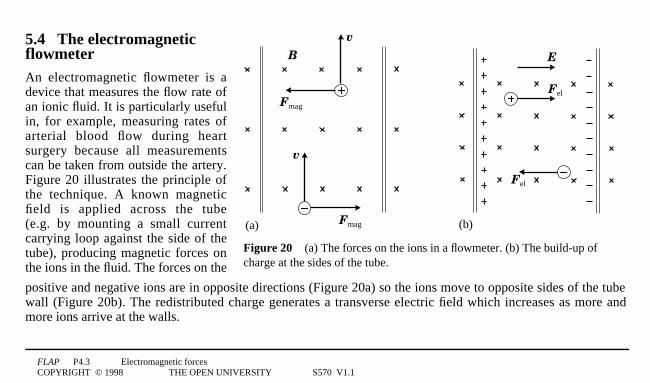
5.4 The electromagneticflowmeterAn electromagnetic flowmeter is adevice that measures the flow rate ofan ionic fluid. It is particularly usefulin, for example, measuring rates ofarterial blood flow during heartsurgery because all measurementscan be taken from outside the artery.Figure 20 illustrates the principle ofthe technique. A known magneticfield is applied across the tube(e.g. by mounting a small currentcarrying loop against the side of thetube), producing magnetic forces onthe ions in the fluid. The forces on the
positive and negative ions are in opposite directions (Figure 20a) so the ions move to opposite sides of the tubewall (Figure 20b). The redistributed charge generates a transverse electric field which increases as more andmore ions arrive at the walls.

FLAP P4.3 Electromagnetic forcesCOPYRIGHT © 1998 THE OPEN UNIVERSITY S570 V1.1
The electric field builds up until the electric force on the ions in the fluid is equal and opposite to the magneticforce. New ions entering the field region of the tube then pass through undeflected, as the Lorentz force on theseions is zero.
The situation is very similar to the null deflection part of Thomson’s e/m experiment, only in Thomson’sexperiment the electric field is applied externally and here it is generated by the redistribution of the chargedparticles themselves, caused by the magnetic deflection when the experiment is first switched on.☞ For ions ofcharge q that pass undeflected through the field region when carried by the fluid with speed v, we have:
v = E
B(Eqn 32)
In practice, we measure the potential difference Vflow developed across the tube of width d , and useEflow = Vflow/d. This potential difference can easily be measured and is proportional to the average velocity of thefluid across the field. The magnitude of the fluid velocity (i.e. its speed) is then given by:
v = Vflow
Bd(36)
Monitoring Vflow is equivalent to monitoring the fluid flow-rate.
FLAP P4.3 Electromagnetic forcesCOPYRIGHT © 1998 THE OPEN UNIVERSITY S570 V1.1
5.5 The Hall effectThe Hall effect is a phenomenon which is similar to that which occurs in the flowmeter, but which may beobserved in metals (with some difficulty) and in semiconductors (rather more easily) ☞. In this case the ‘fluid’is an electric current and the ‘tube’ is typically a rectangular section specimen of a metal or semiconductor.
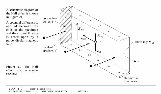
FLAP P4.3 Electromagnetic forcesCOPYRIGHT © 1998 THE OPEN UNIVERSITY S570 V1.1
A
EHall
conventional current I
B
B
B
Fel
Fmagvdrift
I
depth ofspecimen d
thickness ofspecimen t
Hall voltage VHall−e
A schematic diagram ofthe Hall effect is shownin Figure 21.
A potential difference isapplied between theends of the specimenand the current flowingis acted upon by aperpendicular magneticfield.
Figure 214The Halleffect in a rectangularspecimen.
FLAP P4.3 Electromagnetic forcesCOPYRIGHT © 1998 THE OPEN UNIVERSITY S570 V1.1
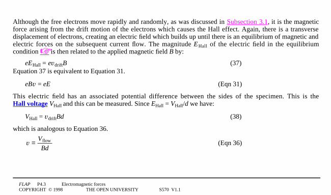
Although the free electrons move rapidly and randomly, as was discussed in Subsection 3.1, it is the magneticforce arising from the drift motion of the electrons which causes the Hall effect. Again, there is a transversedisplacement of electrons, creating an electric field which builds up until there is an equilibrium of magnetic andelectric forces on the subsequent current flow. The magnitude EHall of the electric field in the equilibriumcondition ☞ is then related to the applied magnetic field B by:
eEHall = evdriftB (37)Equation 37 is equivalent to Equation 31.
eBv = eE (Eqn 31)
This electric field has an associated potential difference between the sides of the specimen. This is theHall voltage VHall and this can be measured. Since EHall = VHall/d we have:
VHall = vdriftBd (38)
which is analogous to Equation 36.
v = Vflow
Bd(Eqn 36)
FLAP P4.3 Electromagnetic forcesCOPYRIGHT © 1998 THE OPEN UNIVERSITY S570 V1.1
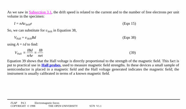
As we saw in Subsection 3.1, the drift speed is related to the current and to the number of free electrons per unitvolume in the specimen:
I = nAvdrifte (Eqn 15)
So, we can substitute for vdrift in Equation 38,
VHall = vdriftBd (Eqn 38)
using A = t0d to find:
VHall = IBd
nAe= IB
net(39)
Equation 39 shows that the Hall voltage is directly proportional to the strength of the magnetic field. This fact isput to practical use in Hall probes, used to measure magnetic field strengths. In these devices a small sample ofsemiconductor is placed in a magnetic field and the Hall voltage generated indicates the magnetic field; theinstrument is usually calibrated in terms of a known magnetic field.
FLAP P4.3 Electromagnetic forcesCOPYRIGHT © 1998 THE OPEN UNIVERSITY S570 V1.1
The other main use of the Hall effect is to study the conductor materials themselves. It is the coefficient 1/ne thatdetermines the size of the Hall voltage for a given current, magnetic field and specimen thickness. If the materialis a good conductor it has a very large concentration of charge carriers (such as in most metals), and therefore avery small Hall voltage. If the material is a rather poor conductor, then it has a rather low concentration ofcharge carriers (as in a semiconductor), and a relatively large Hall voltage. This explains why it is so difficult tomeasure the Hall effect in a metal and why it is more usually observed in semiconductors; the Hall probesmentioned above are invariably made from thin semiconductor wafers.
By paying due attention to the directions of the various fields and motions involved in the Hall effect we canlearn still more about the conduction process in materials. For a given direction of conventional current in aconductor, the charge could in principle be carried by positive charges moving in the conventional direction ornegatively charged electrons moving in the opposite direction. These two situations are equivalent in terms ofthe charge flow but they produce Hall voltages of opposite sign. In contrasting the two situations we need toreverse both the sign of the charge and the drift velocity. Equation 29
Lorentz force law: F = q(E + v · B) (Eqn 29)
then produces the same direction of force on either charge carrier. This means that the charges move to the sameside of the specimen in both cases and, since the charges are opposite, the polarity of the Hall voltage isreversed. Thus, the polarity of the Hall voltage discloses the sign of the charge carriers in the specimen.
FLAP P4.3 Electromagnetic forcesCOPYRIGHT © 1998 THE OPEN UNIVERSITY S570 V1.1
An alternative way to see this is that in the steady state, once the Hall electric field has become established,Equation 29
Lorentz force law: F = q(E + v · B) (Eqn 29)
tells us that (EHall + v · B) must be zero1—1and since v is reversed in the two cases, so too is EHall.
When Hall measurements are made on different materials we find that the charge carriers are negative(electrons) in most metals, such as gold, silver, platinum, aluminium and copper, but positive (so-called holeconduction) in a few metals, such as lead, zinc, iron and in some semiconductors, such as germanium andsilicon. ☞
Question T17
A uniform magnetic field of 0.101T is directed at right angles to the face of a rectangular sheet of copper which is201mm wide and of thickness 0.101mm, in which there is a steady current. If the drift velocity of the electrons inthe copper is 7.351µm1s–1, find the magnitude of the Hall voltage produced between the edges of the sheet.4❏
FLAP P4.3 Electromagnetic forcesCOPYRIGHT © 1998 THE OPEN UNIVERSITY S570 V1.1
6 Closing items
6.1 Module summary1 When a straight wire of length l carrying a current I is subjected to a uniform magnetic field B, it
experiences a magnetic force
Fmag = I1l · B (Eqn 2)
where l is a vector of magnitude l in the direction of the current. The direction of this force is at right anglesto l and B, as given by the corkscrew rule (or the right-hand rule). Its magnitude is given by
Fmag = I1l1B1sin1θ (Eqn 1)
where θ is the smaller angle between l and B.
2 A current carrying coil in a magnetic field may experience a torque. This effect is exploited in moving-coilmeters and in electric motors.
3 The magnitude of the torque Γmag on a coil in a magnetic field is given by
Γmag = µ1B1sin1θ (Eqn 8)
where µ = NIA is the magnetic dipole moment of a coil of N turns and area A that carries a current I, B is thestrength of the magnetic field, and θ is the smaller angle between B and the normal to the plane of the coil.
FLAP P4.3 Electromagnetic forcesCOPYRIGHT © 1998 THE OPEN UNIVERSITY S570 V1.1
4 Since a current produces a magnetic field, and a magnetic field produces a force on a current, there areforces between wires carrying currents. Like currents attract and unlike currents repel.
5 The force per unit length between long straight parallel current carrying wires in a vacuum is used to definethe ampere as one of the basic units of the SI system, and enables current to be measured with a currentbalance.
6 When a particle of charge q travels with velocity v through a point at which the magnetic field is B, itexperiences a magnetic force
Fmag = qv · B (Eqn 19)
This force is at right angles to both v and B in a direction given by the corkscrew rule (or the right-handrule). Its magnitude is given by
Fmag = |1Fmag1| = |1q1|0v0B1sin1θ (Eqn 18)
where θ is the smaller angle between v and B.7 The expression for the magnetic force on a moving charged particle defines the SI unit of magnetic field
strength, the tesla.
FLAP P4.3 Electromagnetic forcesCOPYRIGHT © 1998 THE OPEN UNIVERSITY S570 V1.1
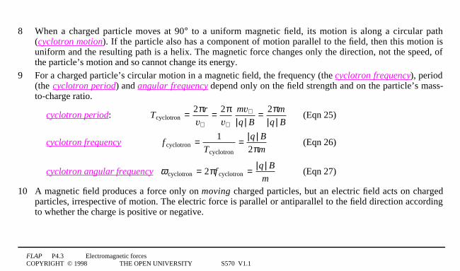
8 When a charged particle moves at 90° to a uniform magnetic field, its motion is along a circular path(cyclotron motion). If the particle also has a component of motion parallel to the field, then this motion isuniform and the resulting path is a helix. The magnetic force changes only the direction, not the speed, ofthe particle’s motion and so cannot change its energy.
9 For a charged particle’s circular motion in a magnetic field, the frequency (the cyclotron frequency), period(the cyclotron period) and angular frequency depend only on the field strength and on the particle’s mass-to-charge ratio.
cyclotron period: Tcyclotron = 2πr
v⊥= 2π
v⊥
mv⊥
|q | B= 2πm
|q | B(Eqn 25)
cyclotron frequency f cyclotron = 1Tcyclotron
= |q | B
2πm(Eqn 26)
cyclotron angular frequency ω cyclotron = 2πf cyclotron = |q | B
m(Eqn 27)
10 A magnetic field produces a force only on moving charged particles, but an electric field acts on chargedparticles, irrespective of motion. The electric force is parallel or antiparallel to the field direction accordingto whether the charge is positive or negative.

FLAP P4.3 Electromagnetic forcesCOPYRIGHT © 1998 THE OPEN UNIVERSITY S570 V1.1
11 The total electromagnetic force acting on a charged particle in the presence of electric and magnetic fields isknown as the Lorentz force, which is expressed in the Lorentz force law:
F = q(E + v · B) (Eqn 29)
12 A charged particle will pass undeviated through a region of crossed electric and magnetic fields only if itsvelocity has a unique value, with a direction perpendicular to the electric and magnetic fields, and amagnitude determined by the ratio of the field strengths:
v = E/B (Eqn 32)
13 A mass spectrometer uses a combination of electric and magnetic fields to separate particles according totheir charge-to mass ratio.
14 If moving charge carriers are confined within a fluid or within a wire, their deflection by a transversemagnetic field produces a voltage. In a fluid the effect is used in the electromagnetic flowmeter. In a metalor semiconductor the effect gives rise to the Hall effect, with the Hall voltage measured at right angles to thefield and to the current. The Hall effect discloses both the sign and the number density of the charge carrierswithin a specimen and can also be used to measure magnetic fields with a Hall probe.
FLAP P4.3 Electromagnetic forcesCOPYRIGHT © 1998 THE OPEN UNIVERSITY S570 V1.1
6.2 AchievementsHaving completed this module, you should be able to:
A1 Define the terms that are emboldened and flagged in the margins of the module.
A2 Recognize the circumstances in which a magnetic field produces a force on a wire and explain how a coilin a magnetic field may experience a torque.
A3 Find the magnitude and direction of the force on a wire, and of the torque on a coil, when a currentcarrying wire or coil is in a uniform magnetic field.
A4 Explain the operation of simple electric motors and moving-coil meters.
A5 State the direction of the magnetic force between two currrents.
A6 Find the magnitude of the force between long straight parallel current carrying wires, and explain how theexpression for the force leads to the definition of the ampere and to the use of a current balance.
A7 Relate the macroscopic effect of a magnetic field on a current to the magnetic forces on individual chargedparticles.
A8 Find the magnitude and direction of the force on a charged particle moving in a magnetic field, and hencedescribe quantitatively the path of such a particle.
FLAP P4.3 Electromagnetic forcesCOPYRIGHT © 1998 THE OPEN UNIVERSITY S570 V1.1
A9 Recall and apply the Lorentz force law for the force on a charged particle in a region containing electricand magnetic fields.
A10 Explain how the Lorentz force law is applied in: Thomson’s determination of e0/me for electrons,Dempster’s mass spectrometer; an electromagnetic flowmeter and the Hall effect.
Study comment You may now wish to take the Exit test for this module which tests these Achievements.If you prefer to study the module further before taking this test then return to the Module contents to review some of thetopics.
FLAP P4.3 Electromagnetic forcesCOPYRIGHT © 1998 THE OPEN UNIVERSITY S570 V1.1
6.3 Exit test
Study comment Having completed this module, you should be able to answer the following questions each of which testsone or more of the Achievements.
Question E1
(A2 and A3)4A rectangular loop of wire with sides of length a and b carries a current I. It is held with its planeparallel to a uniform magnetic field B, first with side a parallel to B and then with side b parallel to B; what isthe maximum torque magnitude in each case?
Question E2
(A2 and A70)4The free charge carriers in a conductor at room temperature are in random thermal motion, eventhough there is no current in the conductor. If the conductor is in a magnetic field, will there be a magnetic forceon each of the charge carriers? Will the conductor experience a force?
FLAP P4.3 Electromagnetic forcesCOPYRIGHT © 1998 THE OPEN UNIVERSITY S570 V1.1
Question E3
(A5 and A6)4When a car engine is started, the current from its starter motor momentarily reaches 1501A.The leads connecting the motor to the battery are 81cm apart. Assuming the leads may be regarded as long andparallel, calculate the magnetic force on a 301cm length of one lead. ☞ Is this force one of attraction or ofrepulsion?
Question E4
(A8)4A particle of mass 3.0 × 10–101kg and charge –1.2 × 10–61C is moving with a velocity of 5.0 × 1031m1s–1 inthe positive y-direction. A uniform magnetic field of 0.201T is then applied in the negative z-direction.Find the initial acceleration of the particle and describe the shape of its subsequent path.
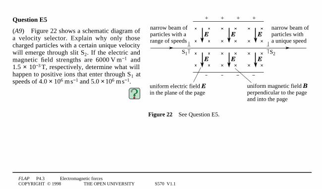
FLAP P4.3 Electromagnetic forcesCOPYRIGHT © 1998 THE OPEN UNIVERSITY S570 V1.1
+ + + +
narrow beam ofparticles witha unique speed
narrow beam ofparticles with a range of speeds
uniform magnetic field B perpendicular to the page and into the page
uniform electric field E in the plane of the page
S1 S2
E E E
E E E
Figure 224See Question E5.
Question E5
(A9)4Figure 22 shows a schematic diagram ofa velocity selector. Explain why only thosecharged particles with a certain unique velocitywill emerge through slit S2. If the electric andmagnetic field strengths are 60001V1m−1 and1.5 × 10−31T, respectively, determine what willhappen to positive ions that enter through S1 atspeeds of 4.0 × 1061m1s−1 and 5.0 × 1061m1s−1.
FLAP P4.3 Electromagnetic forcesCOPYRIGHT © 1998 THE OPEN UNIVERSITY S570 V1.1
Question E6
(A10)4A small rectangular metal sheet of thickness t has a current along its length l. A Hall voltage VHall isgenerated across its width d when the sheet is placed perpendicular to a uniform magnetic field. The numberdensity of free electrons of charge –e in the sheet is n. Show that there is a magnetic force on the sheet whosemagnitude is netlVHall.
Study comment This is the final Exit test question. When you have completed the Exit test go back to Subsection 1.2 andtry the Fast track questions if you have not already done so.
If you have completed both the Fast track questions and the Exit test, then you have finished the module and may leave ithere.