flipw hewlett packard - textfiles.com · installation manual flipw hewlett ~~packard. hp 3000...
TRANSCRIPT

HP 3000 Computer Systems.
HP 3000 SERIES 52/58 UPGRADE
Installation Manual
FliPW HEWLETT~~ PACKARD


HP 3000 Series 52/58 Upgrade
HP 3000 SERIES 52/58 UPGRADE
Installation Manual
r/iOW HEWLETT~~ PACKARD
8010 Foothills Boulevar, Roseville, CA 95678
Part No. 30477-90010E0187
Printed in Mexico
*HP Confidential*
FEDERAL COMMUNICATION COMMISSION RADIO
FREQUENCY INTERFERENCE STATEMENT
The United States Federal Communications Commission (in Subpart J, of Part 15, Docket 20780) has specified thatthe following notice be brought to the attention of the users of this product:
"Warning: This equipment generates, uses, and can radiate radio frequency energy and [{not installed and used inaccordance with the instructions manual, may cause interference to radio communications. It has been testedforcompliance with the limitsfor Class A computing devices pursuant to Subpart J of Part 15 of FCC Rules, which aredesigned to provide reasonable protection against such interference. Operation ofthis equipment in a residential areais like~l' to cause interference in which case the user at his own expense will be required to take whatever measures maybe required to correct the interference".
NOTICE
The information contained in this document· is subject to change without notice.
HEWLETT-PACKARD MAKES NO WARRANTY OF ANY KIND WITH REGARD TO THISMATERIAL, INCLUDING, BUT NOT LIMITED TO, THE IMPLIED WARRANTIES OFMERCHANTABILITY AND FITNESS FOR A PARTICULAR PURPOSE. Hewlett-Packard shall not beliable for errors contained or for incidental or consequential damages in connection with the furnishing,performance or use of this material.
Hewlett-Packard assumes no responsability for the use of reliability of its software on equipment that is notfurnished by Hewlett-Packard.
This document contains propietary information which is protected by copyright. All rights are reserved. No partof this document may be photocopied, reproduced or translated to another language without the prior writtenconsent of Hewlett-Packard Company.
Copyright© 19.78 by HEWLETT-PACKARD COMPANY
ii *HP Confidential*

LIST OF EFFECTIVE PAGES I
The List of Effective Pages gives the date of the most recent version of each page in the manual. To verify that yourmanual contains the most current information, check the dates printed at he bottom of each page with those listedbelow. The date on the bottom of each page reflects the edition or subsequent update in which that page was printed.
Efective Pages Dateall Jan 1987
iii

PRINTING HISTORY
New edditions are complete revisions of the manual. Update packages, which are issued between editions, containadditional and replacement pages to be merged into the manual by the customer. The dates on the title page changeonly when a new edition of a new updated is published. No information is incorporated into a reprinting unless isappears as a prior update; the edition does not change when an update is incorporated.
First Edition JAN 1987
iv

PREFACE
This manual contains procedur~s for upgrading:
Series 39/40/42 systems to Series 52 (S PU and memory) systems
and
Series 44/48* systems to Series 58 (SPU and memory) systems.
The Series 52/58 systems require M PE V/ E (T-MIT or later versions).
Section I describes the Serie~; 39/40/42 to Series 52 SPU and memory upgrade.
Section 2 describes the 44/48* to Series 58 memory upgrade.
Section 3 descri'Jes the Seifte;t Console Messages.
Appendix A contains brief imaructions for returning old system PCAs for credit. Finance and Remarketing Divisionsupplies complete information in the Notice of Return folder.
Additiomd Hevvktt--Packard hlanuals required to perform the upgrade installation procedures are:
HP 3000 Series 39/ 4X/ 5X ('M P/ System Manual, P / N 30090-90005
HP 3000 Series 42XP/52! SS\1emory Diagnostic ]\,Jlanual, P / N 30477-90002
The instaliation procedure d'te box (processing unit) swap upgrade to a Series 52 (32552CH is induded in theSeries 52 Installation MarnaL N 30179-90001.
The installation procedures for the box (processing unit) swap upgrade to a Series 58 (32558Cl1:' IS in:::iuded in theSeries 58 Installation Manual, N 30477-90001.
*The Series 44/48 must be a two card cage configuration in order to upgrade to a Series 58 CPU and memory. A singlecard cage system must first be upgraded using the Series 44 Expansion Kit (30087A).
v

_vi

CONTENTS I
Section ISERIES 39/40/42 TO 52 FIELD UPGRADE
Introduction - , _.. .. .. .. .. I-ICPU Installation. . . . . . . . . . . . . . . . . . . . . . . . . . . . . . . . . . . . . . . . . . . . . . . .. . . . . . . . . . . . . . . . . . . . . . . . . . . . . .. 1-2Memory Installation -. . . . . . . . . . . . . . . . . . . . . . . . . . . . . .. 1-4Changing the Nameplate 1-6Upgrade Sticker Installation ;................................................................ 1-9System Verification -.. .. 1-9
Section 2SERIES 44/48 TO 58 CPU AND MEMORY UPGRADE
Introduction 2-1CPU Installation ., . . . . . . . . . . . . . . . . . . . . . . . . . . . . . . . . . . . . . . . . . . . . . . . . . . . . . . . . . . . . . . . . . . . . . . . . . . . .. 2-2Memory Installation ..................................................•..................... -. .. 2-4Memory Installation - No INPs in Card Cage 2 2-4Memory Installation - With INPs in Card Cage 2 2-9Changing the Nameplate. . . . . . . . . . . . . . . . . . . . . . . . . . . . . . . . . . . . . . . . .. . . . . . . . . . . . . . . . . . . . . . . . . . . . .. 2-13Upgrade Sticker Installation 2-14System Verification 2-1,4
Section 3SELFTEST CONSOLE MESSAGES
Introduction 3-1
Appendix ARETURN PROCEDURE : A-I
vii

viii
SERIES 39/40/42 TO 52 ISECTIONI
~C_PU_A_N_D_M_E_M_O_R_Y_U_'_PG_R_A_D_E__----'------IOJ
INTRODUCTION
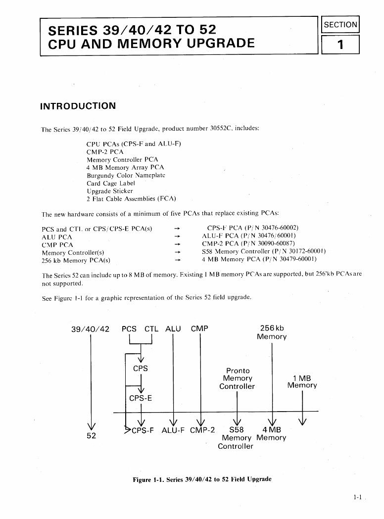
The Series 39/40/42 to 52 Field Upgrade, product number 30552C, includes:
CPU PCAs (CPS-F and ALU-F)CMP-2 PCAMemory Controller PCA4 MB Memory Array PCABurgundy Color NameplateCard Cage LabelUpgrade Sticker2 Flat Cable Assemblies(FCA)
The new hardware consists of a minimum of five PCAs that replace existing PCAs:
PCS and CTL or CPS/ CPS-E PCA(s)ALU PCACMP PCAMemory Controller(s)256 kb Memory PCA(s)
-----CPS-F PCA (P/ N 30476-60002)
ALU-F PCA (P/N 30476/60001)CMP-2 PCA (P/N 30090-60087)S58 Memory Controller (P / N 30172-60001)4 MB Memory PCA (P/N 30479-60001)
The Series 52 can include up to 8 MB of memory. Existing 1 MB memory PCAs are supported, but 256'kb PCAs arenot supported.
See Figure 1-1 for a graphic representation of the Series 52 field upgrade.
39/40/42 PCS ClL ALU CMP
CPS
CPS-E
ProntoMemory
Controller
256kbMemory
1 MBMemory
52CPS-F ALU-F CMP-2 S58 4 MB
Memory MemoryController
Figure 1-1. Series 39/40/42 to 52 Field Upgrade
1-1

Series 39/40/42 to 52 Field Upgrade
CPU INSTALLATION
Materials used in this procedure are the CPS-F PCA (PIN 30476-60002), the ALU-F PCA (PIN 30476-60001), theCM P-2 PCA (PIN 30090-60087), two four-card FeAs (PIN 30000-93054), anda card cage label (PI N 30550-80202).
No tools are needed.
See Figure I-2 while performing the CPU and Memory installation procedures.
1 2 3 4 5 6 7 8 9 10 11 12 13 14 15 16 17 1819 20 21 22 232425
M ccc;JU; U; U. emory I- a..:::J (J) g U UZ~--l a.. « (5(3u u « u
- - - --1:. - n:.- It. -Q.-~- j---It - - - - - - - -- - - - - - - - - - - - ... - --~~--! -~-
J1
..... ..... ..... I-- -..-
- - rol I-- - I"' - I--~ 11 ~ l:- - -- - ,.. -. - ~ - - - - - - - - - - - -.-I-- ~ __
J2
~ ~ ~
- --- ~--lf-~ ..... If-------r: -,..1-------------I---
J3
-...... - --1--- -f1--':JI.--~---- -- -1---------------
II .~~
Figure 1-2. Series 52 PCA Card Cage
ICAUTION IESD protection requires the use of a grounded wrist strap when handling PCAs.
1-2

Series 39/40/42 to 52 Field Upgrade
1. Verify that the system operator has backed up the system, logged off all users, and performed and MPE shutdown.
2. Set the POWER switch to OFF. Unplug the AC power cord or set the main breaker switc~ off.
3- Remove the back panel from the cabinet by loosening the captive screws, pulling the panel slightly forward, andlifting tht1 panel off the bottom of the cabinet.
NOTE~
The existing computer may have either a two - or three - PCA CPU. Steps 4and 5 describe the procedure for both CPUconfigurations. Perform the procedure that applies to the existing computer.
4. Disconnect the cables at JI, 12 and J3 on the PCAs in slots 6, 9, 11, 13, and 15(CMP, ALU, CPS-E, ADCC, and GIC).
Disconnect the cables at 11,12, and J3 on the PCAs in slots 6, 7, 9,11,13, andIS (CMF, PCS, ALU, CTL, ADCC, and GIC).
5.ADCC, and GIC).
Remove the PCAs from slots 6, 9, 11, 13, and 15 (CMP, ALU, CPSj CPS-E,
ADCC, and GIC).Remove the PCAs from slots 6, 7, 9, 11, 13, and 15 (CMP, PCS, ALU, CTL,
I CAUTION I
Before performing Step 6, ensure that the correct PCAs have been removed. If the CPS-F PCA is installed with aCTL, PCS, or CPS PCA, all PCAs will be damaged at powerup.
6. Install the CMP-2 PCA in slot 6, the ALU-F PCA in slot 7, the CPS-F PCA in slot 9, the ADCC PCA in slot 13,and the GIC PCAs in slots 15 and 16.
7. Reconnect the appropriate cables atlI, 12 and 13 ofthe CMP-2, the ALU-Fthe,CPS-Ij',lthe ADCC, and the GICs inslots 6, 7, 9, 13, 15, and 16, respectively.
8. Attach the new card cage configuration label over the existing card cage label. If you have more than one label onthe existing sYistem, you may want to use a screwdriver to pry the old labels off before attaching the new label.Verifty that the new label correctly identifies the new card cage configuration.
1-3

Series 39/40/42 to 52 Field Upgrade
MEMORY INSTALLATION
,Materials used in this procedure are the S58 Memory Controller PCA (PIN 30172-60001), 4 MB Memory PCA(s)(PIN 30479-600(1), 2 MB Memory PCA(s) (PIN 30478-60001, and existing 1 MB Memory PCAs (PIN 3016160001). The 256 kb Memory PCAs (PIN 30092-60001) are not supported. Up to four memory PCAs are supported,for a maximum of 8 MB of memory.
See Figure 1-2 while performing the following procedure.
I. Remove the flat cable at J 1 on the Memory Controller and memory PCAs.
2. Remove the Memory Controller from slot 5 and the memory PCAs from slots 1 through 4.
3. Set the S58 Memory Controller configuration switch (located near the right backplane edge of the PCA) so that allthree switches are in the down position. See Figure 1-3 for switch positions.
II
II
II
II
II
II
II
II
Figure 1-3. S58 Memory Controller Switch Positions
4. Install the S58 Memory Controller PCA in slot 5.
5. Star with slot 1 and install the memory PCAs in the following order:
a. Installed all of the 2 MB Memory PCAs (PIN 30478-60001).
b. Then installed all of the 4 MB Memory PCAs (PIN 30479-60001).
c. Finally installed all of the 1 MB Memory PCAs (PIN 30161-60001).
Some of these PCAs may not be present. Up to, but not more than, 8 MB of memory can be installed in the Series 52.
1-4

Series 39/40/42 to 52 Field Upgrade
6. You must set the memory address switches as shown in the table below that matches your memory configuration.To understand the switch settings for the 2 MB Memory PCAs(P/ N 30478-60001) and the 4 MB Memory PCAs(P / N 30479-6000 I), consider these boards to be sets of two and four 1 MB PCAs. The memory address switchshould be set to the position corresponding to the first megabyte of those sets.
Table 1.,.1. Series 52 with 5 MB of Memory
Card Cage Memory AddressSlot Number PCA Size Switch Setting
I 2MB 0
2 1MB 2
3 1 MB 3
4 1 MB 4
Table 1-2. Series 52 with 6 MB of Memory
Card Cage Memory AddressSlot Number PCA Size Switch Setting
I 4 MB 0
2 1 MB 4
3 1MB 5
4 --- ---
Table 1-3. Series 52 with 8 MB of Memory
Card Cage Memory AddresssSlot Number PCA Size Switch Setting
I 4 MB 0
2 4 MB 4
3 --- ---
4 --- ---
1-5

Series 39/40/42 to 52 Field Upgrade
Table 1-4. Series 52 with 8 MB of Memory
Card Cage Memory AddressSlot Number PCA Size Switch Setting
I 2 MB 0
2 4MB 2
3 1MB 6,
4 1MB 7
7. Reinstall the flat cable at J I on the Memory Controller and memory PCAs.
8. Using standard field return shipping procedures, return the old PCAs for credit. Appendix A covers theseprocedures in more detail.
CHANGING THE NAMEPLATE
This procedure describes replancing the Series 39/40/42 nameplate with a Series 52 nameplate. The new nameplatewill read Series 52, but will De burgundy color rather dark grey.
Tools required for this procedure are a large Posidriv ® screwdriver, a small Posidriv ® screwdriver, two flat bladescrewdrivers, and a 3/ 16-inch nut driver.
I. Using a large Posidriv® screwdriver, loosen the two blackscrews securing the shroud at top rear of the computercabinet (above card cage). Remove the shroud by sliding it back and a way from the front of the computer cabinet.
I CAUTION IESD protection requirers the use of a grounded wrist strap when handling PCAs.
2. Jnside the cabinet and behind the nameplate is a small LED PCA. Using a small Posidriv® screwdriver, remove thetwo screws securing the PCA. Move the PCA to one side.
3. A ground wire is connected from chassis to the nameplate bolt. Using a 3/ 16-inch nut driver, remove the two nutsholding the ground wire to the bolt. Remove flat washer and spacer.
1-6

Series 39/40/42 to 52 Field Upgrade
NOTE
At this point, the nameplate is still held in place by double-sided tape installed at the factory. Perform Step 4 to pry thenameplate from the front panel. Pressure can be applied to the back side of the nameplate at two places: the bolt and asmall slot just below the bolt.
4. Insert a flatblade screwdriver into the slot below the bolt and gently push the nameplate forward. Then push thenameplate bolt until the top edge of the nameplate separates from the front panel. Be careful not to scratch the painton the front panel. Discard the old nameplate. Remove any remnants of old tape from the front panel beforeinstalling the new nameplate.
5. Remove protective backing from tape on back side of new nameplate and install.
6. Reinstall spacer, flat washer, ground, wire, and two nuts.
7. Reinstalled LED PCA.
8. Reinstalled and secure the shroud to the computer cabinet.
1-7

Series 39/40/42 to 52 Field Upgrade
NOTE
Ensure that the RFI fingers on the front and back panels make complete contact with the RFI brackets around thecard cage. See Figure 1-4
. ' .. ' .. '.". " .. ' .. "
' .., '.
RFI Brackets
Figure 1-4. Series 52 - Front View (RFI Brackets)
1-8

Series 39/40/42 to 52 Field Upgrade
UPGRADE STICKER INSTALLATION
Place the adhesive upgrade sticker on the top rear of compufer cabinet, near the serial number. See Figure 1-5 for thecorrect location.
~Pl
I Model II Warranty I
UL
CSA
~'\
\.
I \ I
Figure 1-5. Upgrade Sticker Location (rear view of 39/40/42)
SYSTEM VERIFICATION
I. Reinstall back cover.
2. Plug in AC power cord. Turn on power switch.
3. Execute CM PI system selftest by typing SELFTEST at the CM P prompt (-». Refer to Section 3 of this manualfor adescription of the selftest console messages. For additional selftest information, refer to the HP 3000 Series39/4X/5X System CM PI Selftest Manual (PIN 30090-90005).
4. Run the M DIAG 58 memory diagnostic to verify correct operation ofthe memory subsystem. Refer to the H P 3000Series 42XP152/58 M DIAG 5X Memory Diagnostic Manual (PIN 30477-90002) for instructions.
1-9

'---S_E_R_I_E_S_4_4_1_4_8_T_O_5_8 1~2TIONI_MEMORY UPGRADE ~
~
INTRODUCTION
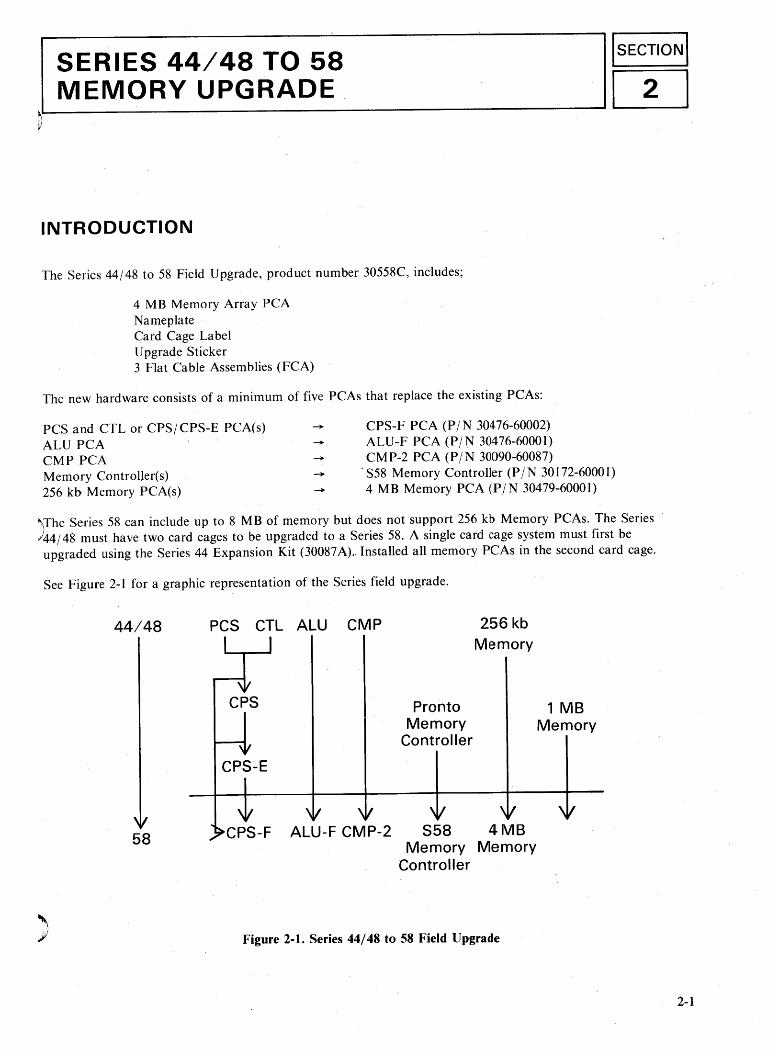
The Series 44/48 to 58 Field Upgrade, product number 30558C, includes;
4 MB Memory Array PCANameplateCard Cage LabelUpgrade Sticker3 Flat Cable Assemblies (FCA)
The new hardware consists of a minimum of five PCAs that replace the existing PCAs:
PCS and CTL or CPSI CPS-E PCA(s)ALU PCACMP PCAMemory Controller(s)256 kb Memory PCA(s)
CPS-F PCA (PIN 30476-60002)ALU-F PCA (PIN 30476-60001)CM P-2 PCA (PIN 30090-60087)
. S58 Memory Controller (P IN 30172-60001)4 MB MemoryPCA (PIN 30479-60001)
)The Series 58 can include up to 8 MB of memory but does not support 256 kb Memory PCAs. The Series44/48 must have two card cages to be upgraded to a Series 58. A single card cage system must first beupgraded using the Series 44 Expansion Kit (30087A) .. Installed all memory peAs in the second card cage.
See Figure 2-1 for a graphic representation of the Series field upgrade.
44/48 PCS CIl AlU CMP
CPS-E
ProntoMemory
Controller
256 kbMemory
1 MBMemory
)
58 CPS-F AlU-F CMP-2 S58 4 MBMemory Memory
Controller
Figure 2-1. Series 44/48 to 58 Field Upgrade
2-1

Series 44/48 to 58 Memory Upgrade
CPU INSTALLATION
Materials used in this procedure are the CPS-F PCA (P/ N 30476-60002), the ALU-F PCA (P/ N 30476-6000 I), theCM P-2 PCA (P/ N 30090-60087), two three-card FCAs (P/ N 30000-93053), and a card cage label (P / N 30477-80200).No tools are needed.
See Figure 2-2 while performing the following procedure.
1 2 3 4 5 6 7 8 9 10 11 12 13 14 15 16 17 18 19 20 21 22 23 24memory bus ~ i t ~ ~ ~
- - - - - ;D ~ Jt • It - - -,IrJl-n-j- - ~ - - - - - - - - -. - - ~- .. ...
J1I- I-
---~]-n-]-- - -----------1I- -
J2
1=---------- ... ~J3
--;.... I--
Card Cage #1
1 2 3 4 5 6 7 8 9 10 11 12 13 14 15 16 17 18 19 20 21 22 23 24Input/output ~ memory' Input/output
--------j---~~~-~~-----------I- I- I- -
J1
J2
J3
---------
- --------
~ -----1---1-------------u
l!) '"
o 0§ §: \E ~
~ ~~ a:------I-~~-----------
- -------- ---- - -1--1------------'requires 9-card ribbon cable Card Cage #2
2-2
Figure 2-2. Series 58 PCA Card Cages

Series 44/48 to 58 Memory Upgrade
NOTE
If no IN P PCAs (P! N 30020-60009) are installed in card cage 2, install all of the memory PCAs in card cage 2.
If any IN P PCAs (P / N 30020-60009) and associated G ICs are installed in card cage 2, install all of the memory PCAsin card cage I
I CAUTION I
ESD protection requires the use of a grounded wrist strap when handling PCAs.
I. Verify that the system operator has backed up the system, logged off all users, and performed an M PE shutdown.
2. Set the POWER switch to OFF. Unplug the AC power cord or set the system's circuit breaker off.
3. Open the rear card cage doors. Perform this proced ure in card cage I.
NOTE
The existing computer may have either a two- or three- PCA CPU. Steps 4 and 5 describe the~procedure for bot h (. Pl!configurations. Perform the procedure that applies to the existing computer.
Disconnect the cables at J I" J2. and .13 on the PCAs in slots 10. II 13. 12. 14., ADCC and GIC).
Disconnect the cables at J I . .12. and J3 on the PCAs in slots 10. II. 12. 13.14.and 16 (CM p. PCS, ALU, CTL, ADCC and GIC).
5.ALU, ADCC, and GIC).
Remove the PCAsfromslots 10. II 13. 12. 14. and 16(CMP.CPS CPS-I-:.
CTL, ADCC, and GIC).Remove the PCAs from slots 10. 11.12.13.14. and 16 (CMP. PCS. All!.
I CAUTION I
Before performing Step 6. ensure that the correct PCAs heve been removed. If the CPS-F PCA is installed \\ith a CII ..PCS, or CPS PCA, all PCAs will be damaged at powerup.
2-3

Series 44/48 to 58 Memory Upgrade
, 6.lnstalled the CPM-2 PCA in slot 10, the CPS-F PCA in slot II, the G IC PCA in slot 14, and the ADCC PCA in slot15.
7. Reconnect the appropriate at J I, J2, and J3 of the CMP-2, the CPS ALU-F, the GIC, and the ADCC in slots 10, II,12, 14, and 15 respectively.
8. Attach the new card cage configuration label over the existing card cage label. Verify that the new label correctlyidentifies the new card cage configuration.
MEMORY INSTALLATION
Memory can be installed in two configurations. If there are no INPs in card cage 2, all memory is installed in card cage2. If there are any INPs and associated GICs in card cage 2, all memory is installed in card cage I.
Memory Installation - No INPs In Card Cage 2
Materials used in this procedure are the S58 Memory Controller PCA (P IN 30172-60001),4 MB Memory PCAs{PIN30479-60001),2 MB Memory PCAs (PI N 30478-60001), existing I MB Memory PCAs (PIN 30161-60001), and a 9board FCA (PIN 30094-60002). The 256 kb Memory PCAs (PIN 30092..6000 I) are not supported. Up to five memoryPCAs are supported, for a maximum of 8 MB of memory.
NOTE
A Series 44/48 with a single card cage must have a second card cage (30087A) to be upgraded to a Series 58. Install allmemory PCAs in card cage 2.
See Figure 2-2 while performing the following procedure.
I. Remove the flat cable at J I on the Memory Controller(s) and memory PCAs.
2. Remove the Memory ,Controller(s) from slot 9 in card cage I andl or slot 8 in card cage 2 and remove the memoryPCAs from slots I through 8 in card cage I and/or slots 9 through 16 in card cage 2.
3.0n the backplane of card cage I, set the MEMI NO MEN switch to the NO MEN position. On card cage 2, set theswitch to MEM. ~
4. Set the S58 Memory Controller configuration switch (located near the right backplen edge of the PCA) so that allthree switches are in the down position. See Figure 2-3 for switch positions.
2-4

Series 44/48 to 58 Memory Upgrade
II
II
II
II
II
II
II
II
Figure 2-3. S58 Memory Controller Switch Positions
5. Install the S58 Memory Controller PCA in slot 8 of card cage 2.
6. Star with slot 16 in card cage 2. Install the memory PCAs in descending numbered slots in this order.
a. Install all of the 2 M B Memory PCAs (PIN 30478-6000 I).
b. Then install of the 4 MB Memory PCAs (PIN 30479-60001).
c. Finally install all of the I MB Memory PCAs (PIN 30161-60(01).
Some of these PCAs may not be present. Up to, but not more than, 8 MB of memory can be installed in the Series
58. No more than five memory peAs can be installed in the Series 58.
7. You must set the memory address switches as shown in the table below matching your memory configuration. Tounderstand the switch settngs for the 2 MB Memory PCAs (Pi N 30478-6000 I) and the 4 M B Memory PCAs (P :\30479-6000 I), consider these boards to be sets of two and four 1MB PCAs. The memory address switch should be
set to the position corresponding to the first megabyte of those sets.
2-5

2-6
Series 44/48 to 58 Memory Upgrade
Table 2-1. Series 58 with 5 MB of Memory
Card Cage 2 Memory AddressSlot Number PCA Size Switch $etting
16 2 MB 0
15 1MB 2
14 1MB 3
13 1MB 4
12 --- ---
Table 2-2. Series 58 with 6 MB of Memory
Card Cage 2 Memory AddressSlot Number PCA Size Swtich Setting
16 2 MB 0
15 4 MB 2
14 --- ---
13 --- ---
12 --- ---

Series 44/48 to 58 Memory Upgrade
Table 2-3. Series 58 with 8 MB of Memory
Card Cage 2 Memory AddressSlot Number PCA Size Switch Setting
"
16 4 MB 0
15 1MB 4
14 1MB 5
13 I M'B 6
12 1MB 7
Table 2-4. Series 58 with 8 MB of Memory
Card Cage 2 Memory AddressSlot Number PCA Size Switch Setting
16 4 MB 0
15 4 MB 4
14 --- ---
13 --- ---
12 --- ---
Table 2-5. Series 58 with 8 MB of Memory
Card Cage 2 Memory Add ressSlot Number PCA Size Switch Setting
16 2 MB 0
15 2 MB 2
14 4 MB 4
13 --- ---
12 --- ---
- 2-7

Series 44/48 to 58 Memory Upgrade
x. Reinstall (or install) the flat cable (P / N 30094-60002) at J I on the Memory Controller and memory peAs.
9. Using standard field return shipping procedures, return the old peAs for credit. Appendix A covers theseproced ures in more detail.
2-8

Series 44/48 to 58 Memory Upgrade
Memory Installation - With INPs In Card Cage 2
Materials used in this procedure are the S58 Memory Controller PCA (PIN 30172-6000 1),4 M B Memory PCAs (Pi N30479-60001),2 MB Memory PCAs (PIN 30478-60001), existing I MB Memory PCAs (PIN 30161-600(1), and a 9board FCA (PIN 30094-60002). The 256 kb Memory PCAs (PIN 30092-6000 I) are not supported. lip to five memoryPCAs are support, for a maximum of 8 MB of memory.
NOTE
A Series 44/48 with a single card cage must have a second card cage (30087A) to be upgraded to a Series 58C. Install allmemory PCAs in card cage I.
See Figure 2-2 while performing the following procedure.
I. Remove the flat cable at J I on the Memory Controller(s) and memory PCAs.
2. Remove the Memory Controller(s) from slot 9 in card cage I and/ or slot 8 in card cage 2 and remove the memoryPC As from slots I through 8 in card cage I andl or slots 9 through 16 in card cage 2.
3. On the backplane of card cage I, set the ME M I NO M EN switch to the ME M position. On card cage 2, set the switchto the NO MEM position.
4. Set the S58 Memory Controller configuration switch (located near the right backplane edge of the PCA) so that allthree switches are in the down position. See Figure 2-4 for switch positions.,
\ II I\ I
\ /\ I\ II II I\ I\ I\ I\ II I\ I\ I
Figure 2-4. SS8 Memor)' Controller Switch Positions
5. Install the S58 Memory Controller peA in slot 9 of ca rd cage I.
2-9

Series 44/48 to 58 Memory Upgrade
6. Start with slot I in card cage I. Install the memory PCAs in descending numbered slots in this order:
a. Install all of the 2 MB Memory PCAs (PIN 30478-60001).
b. Then install all of the 4 M B Memory PCAs (PIN 30479-6000 I).
c. Finally install all of the I MB Memory PCAs (PIN 30161-60001).
Some of these PCAs may not be present. Up to but not more than, 8 M B of memory can be installed in the Series 58.No more than five memory peAs can be installed in the Series 58.
7. You must set the memory address switches as shown in the table below matching your memory configuration. Tounderstand the switch settings for the 2 MB Memory PCAs (PIN 30478-60001) and the4 MB Memory PCAs(PI N
30479-6000 I), consider these boards to be sets of two and four 1MB PCAs. The memory address switch should be setto the position corresponding to the first megabyte of those sets.
Table 2-6. Series 58 with 5 MB of Memory
Card Cage I Memory AddressSlot Number PCA Size Switch Setting
I 2 MB 0
2 1MB 2
3 1MB 3
4 1MB 4
5 --- ---
Table 2-7. Series 58 with 6 MB of Memory
Card Cage I Memory AddressSlot Number PCA Size Switch Setting
I 2 MB 0
2 4 MB 2
I
3 --- ---
4 --- ---
5 --- ---
2-10
Series 44/48 to 58 Memory Upgrade
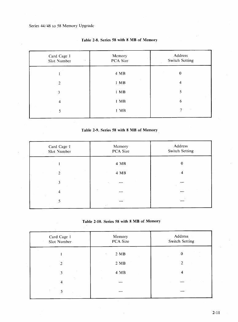
Table 2-8. Series 58 with 8 MB of Memory
Card Cage I Memory AddressSlot Number PCA Size Switch Setting
I 4 MB 0
2 1MB 4
3 1MB 5
4 1MB 6
5 1MB 7
Table 2-9. Series 58 with 8 MB of Memory
Card Cage I Memory AddressSlot Number PCA Size Switch Setting
I 4 MB 0
2 4 MB 4
3 --- ---
4 --- ---
5 --- ---
Table 2-10. Series 58 with 8 MB of Memory
Card Cage I Memory AddressSlot Number PCA Size Switch Setting
1 2 MB 0
2 2 MB 2
3 4 MB 4
4 --- ---
5 --- ---
2-11

Series 44/48 to 58 Memory Upgrade
8. Reinstall (or install) the flat cable (P / N 30094-60002) at J I on the Memory Controller and memory PCAs.
9. Using standard field return shipping procedures, return the old PCAs for credit. Appendix A covers theseprocedures in more detail.
2-12.

Series 44/48 to 58 Memory Upgrade
CHANGING THE NAMEPLATE
This procedure describes replacing the Series 44/48 nameplate with a Series 58 nameplate. A flatblade screwdriver isrequired for this procedure.
I; Use the key to unlock the front panel. Swing the panel open to the right.
2. Unscrew the two nuts on the top back of the nameplate.
3. From the back of the nameplate, use the flatblade screwdriver to pry the adhesive-backed nameplate from the panel.
4. Remove the old adhesive from the panel before installing the new nameplate.
5. Remove the protective backing from adhesive on the back side of the new nameplate.
6. Position the new nameplate so that the two small screws through the holes in the panel.
7. Reinstall the two nuts.
NOTE
Ensure that the RFI fingers on the front and back panels make complete contact with the RFI brackets around thecard cage. See Figure 2-5
I
/
\ I
VRFI Brackets
Figure 2-5. Series 58 - Back View (RFI Brackets)
8. Secure with the key.
2-13

Series 44/48 to 58 Memory Upgrade
UPGRADE STICKER INSTALLATION
Place the adhesive upgrade sticker on the back of the computer cabinet, near the serial number on the lower leftcorner. See Figure 2-6.
Iwarning I
B BB [IT] [IT][IT][]]
:8 8:ITIJ IModel I I I
Warranty ,I ,
~Figure 2-6. Series 44/48/58 Power Control Module Rear View
SYSTEM VERIFICATION
I. Plug in AC power cord. Power up cabinet.
2. Execute CMP/system selftest by typing SELFTESTat the CMP promp (-». Refer to Section 30fthis manual foradescription of the selftest console messages. For additional selftest information, refer to HP 3000 Series 39I4X/ 5XSystem CMP/Selftest Manual (PIN 30090-90005).
3. Run the MDIAG 58 memory diagnostic to verify correct operation of the memory subsystem. Refer to the HP 3000Series 42XP152/58 MIDIAGS8 Memory Diagnostic Manual (P/ N 30477-90002) for instructions.
2-14

1L.-- 1~3TIONI~ElFTESTCONSOLE MESSAGES ~
INTRODUCTION
The selftest console messages· are:
CMP TESTRAM test passedROM test passedUART test passed
CMP-CPU InterfaceSWITCH = 00test passed
CPU TEST000004000800OCOO1000140018001COO2000240028002COO3000340038003COOtest passed
CONTROL PANELSTATUS = 06 SYS DISC = NORMtest passed
ADCC TRANSMIT test passed
ADCC RECEIVE test passed
GIC TEST CHL = 11 test passed
SYSTEM TEST passed
->
3-1


RETURN PROCEDURE IIAPP.ENDIX.I
'----~----,-- -I A I
Finance and Remarketing Oivision (FRO) supplies the following items in the Notice of Return (NOR) folder:
Returner Equipment Verification (REV)Upgrade Equipment Return InstructionsNotice of Return (NOR) Authorization FormShipping Labels (adhered to shipping pouches)
Follow FRO's procedures to facilitate the return of PCAs for which upgrade credits have been issued. If thePCAs do not arrive at FRO within 30 days (60 days outside the U.S. and Canada), your office will becontacted for return order status.
The specific responsibilities of the CE are:
1. Ensure that thePCAs are fully operational.
2. Any discrepancies between what is listed on the REV and the products being returned should immediately hereported to FRO's Order Processing department.
3. Pack the de-installed PCAs in anti-static material, along with the REV, and return them to your shippingdepartment.
4. Call FRO's Orders Processing department to make shipping arrangements.
A-I

I
I
I
I
I
I
I
I
I
I
I
I
I
I
I
I
I
I
I
I
I
I
I
I
I
I
I
I
I
I
I
I
I
I
I
I
I
I
I
I
I
I
I
I
I
II
I
I
I
I
I
I
I

READER COMMENT SHEETUP 3000 Computer Systems
UP 3000 SERIES 52/58Upgrade Installation Manual
30477-90010 January 1987

FOLD
111111
FOLI
NO POSTAGENECESSARYIF MAILED
IN THEUNITED STATES
FIRST CLASS PERMIT NQ. 256 ROSEVILLE, CALIFORNIA
BUSINESS REPLY MAI'L
Publications ManagerHewlett-Packard CompanyOffice Systems Division8010 Foothills BoulevardRoseville, CA 95678
••••••••••••••••••••••••••••••••••••••••••••••••••••••••••••••••••••••••••••••••••••••••••••••••••••••••••••••••••••••••••••••••••••••••••••••POSTAGE WILL BE PAID BY ADDRESSEE •••••••••
•••••••••••••••••••••••••••••••••••••••• 1 ••••
FOLD FOLI


Part No. 30477-90010Printed in Mexico 06/88EOl87
r/in- HEWLETT.:~ PACKARO