flygt (xylem) 5540, pompe relevage assainissement - … · 2 product description applications 5530...
TRANSCRIPT

TECHNICALSPECIFICATION
5530.1815540.181
2
PRODUCT DESCRIPTIONApplications5530 and 5540 are intended to be used for:
— pumping of water which may contain abrasiveparticles
— pumping of sludge
— pumping of ground water
— pumping of light slurries.
The pump is available in the following versions:
HP = for permanent installation in a sump. Thepump slides down along the guide arrange-ment and connects automatically to a dis-charge connection.
HS = transportable version with stand and connec-tion for hose or pipe.
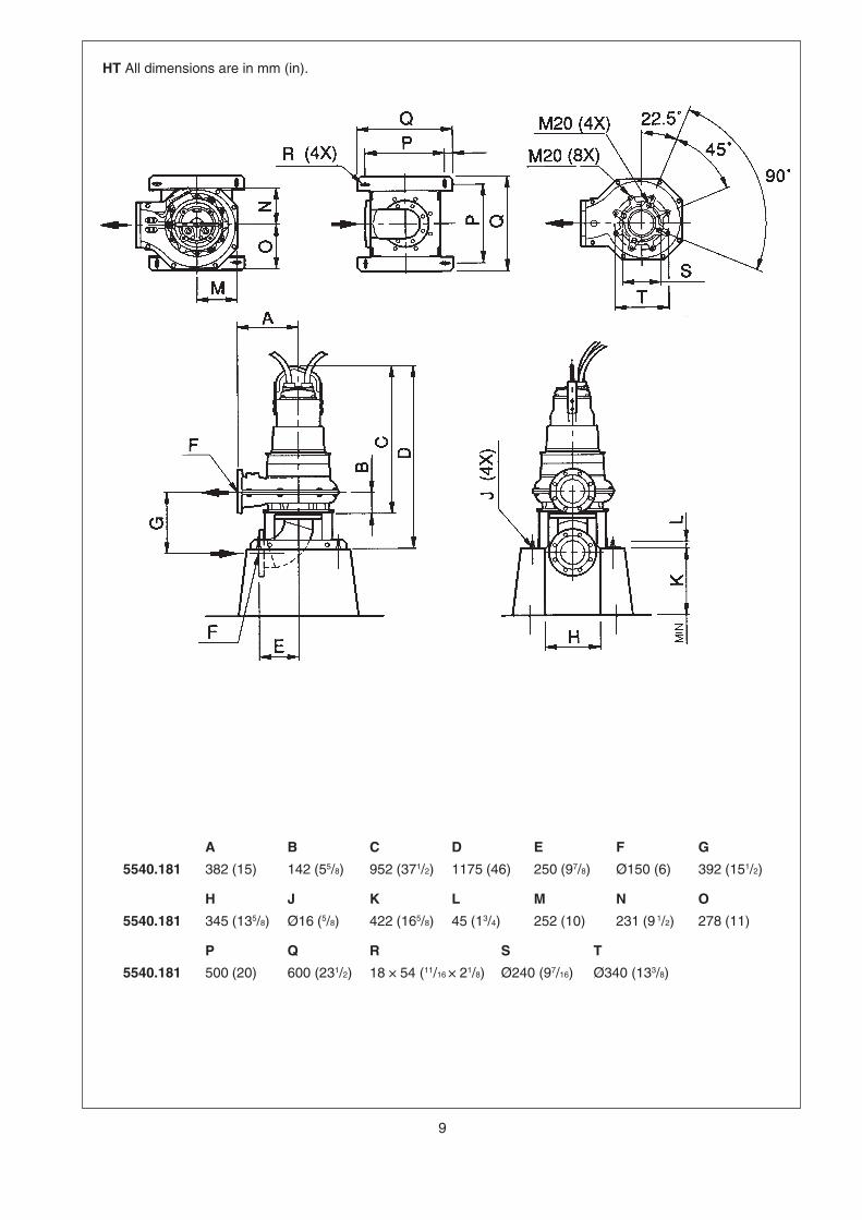
HT = for a vertical dry stationary installation on astand. Directly connected to the inlet andoutlet lines.
HZ = for a horizontal dry stationary installation on asled. Directly connected to the inlet and outletlines.
Liquid temperature: max. 40°C (105°F).
The pump is also available in a version for liquidtemperatures up to 70°C. These versions have certainoperational limitations which are stated on a plate onthe pump.
Liquid density: Depending on the sduty point.
The pH of the pumped liquid: 6—14.
Lowest liquid level: above the pump.
Depth of immersion: max. 20 m (65 ft).
WARNING!The pump may not be used in an explosive or
flammable environment or for pumpingflammable liquids.
For other applications, than the above, contact yournearest Flygt representative for information.
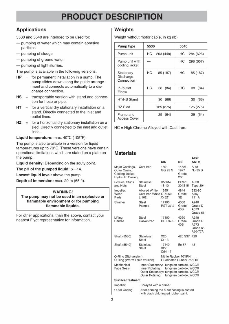
WeightsWeight without motor cable, in kg (lb).
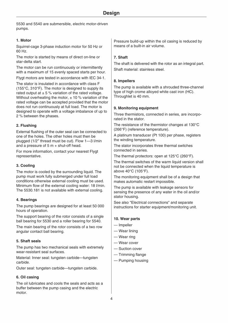
MaterialsAISI/
DIN BS ASTM
Major Castings, Cast Iron 1691 1452: A 48Outer Casing, GG 25 G 1977 No 35 BCooling Jacket, GradeHydraulic Casing 260
Screws, Studs Stainless X5CrNi BS970 A320and Nuts Steel 18 10 304S15 Type 304
Impeller, Alloyed White 1695 4844 532-80Wear Cast Iron White G-X260 Grade AlloyParts L 102 Cr 27 3E 111 A
Strainer Steel 17100 4360 A248Painted RST 37-2 Grade Grade D
40B A573Grade 65
Lifting Steel 17100 4360 A248Handle Galvanized RST 37-2 Grade Grade D
40B A573Grade 65A36-77A
Shaft (5530) Stainless X20 420 S37 420Steel Cr 13
Shaft (5540) Stainless 17440 En 57 431Steel X22
CrNi 17
O-Ring (Std-version) Nitrile Rubber 70°IRHO-Ring (Warm-liquid version) Fluorinated Rubber 75°IRH
Mechanical Inner Stationary: tungsten carbide, WCCRFace Seals: Inner Rotating: tungsten carbide, WCCR
Outer Stationary: tungsten carbide, WCCROuter Rotating: tungsten carbide, WCCR
Surface treatment
Impeller: Sprayed with a primer.
Outer Casing After priming the outer casing is coatedwith black chlorinated rubber paint.
Pump type 5530 5540
Pump unit HC 203 (448) HC 284 (626)
Pump unit with — HC 298 (657)cooling jacket
Stationary HC 85 (187) HC 85 (187)DischargeConnection
In-/outlet HC 38 (84) HC 38 (84)Elbow
HT/HS Stand 30 (66) 30 (66)
HZ Sled 125 (275) 125 (275)
Frame and 29 (64) 29 (64)Access Cover
HC = High Chrome Alloyed with Cast Iron.

3
Motor data
5530.181 5540.181
50 Hz, HP/HS 5.9 kW3 ~, 4-pole, 1450 r/min
Voltage Rated StartingV current A current A
220 21 127380 12 73415 11 64500 9.5 60660 7.1 42
60 Hz, HP/HS 10 hp (7.5 kW)3 ~, 4-pole, 1740 r/min
Voltage Rated StartingV current A current A
230 25 156460 13 82575 10 62600 9.7 55
50 Hz, HP/HS 13.5 kWHT/HZ 13.5 kW
3 ~, 4-pole, 1450 r/min
Voltage Rated StartingV current A current A
220 50 280380 28 161415 26 140500 21 126660 17 93
60 Hz, HP/HS 20 hp (14.9 kW)HT/HZ 20 hp (14.9 kW)
3 ~, 4-pole, 1750 r/min
Voltage Rated StartingV current A current A
230 53 345460 26 173575 20 115600 20 121
5530.181 5540.181
Rated output
The pump is available with following motors:
5530.181
50 Hz5.9 kW, for HP/HS-version
60 Hz10 hp (7.6 kW), for HP/HS-version
5540.181
50 Hz13.5 kW, for HP/HS-version13.5 kW, for HT/HZ-version*
60 Hz20 hp (14.9 kW), for HP/HS-version20 hp (14.9 kW), for HT/HZ-version*
* With external cooling.
4
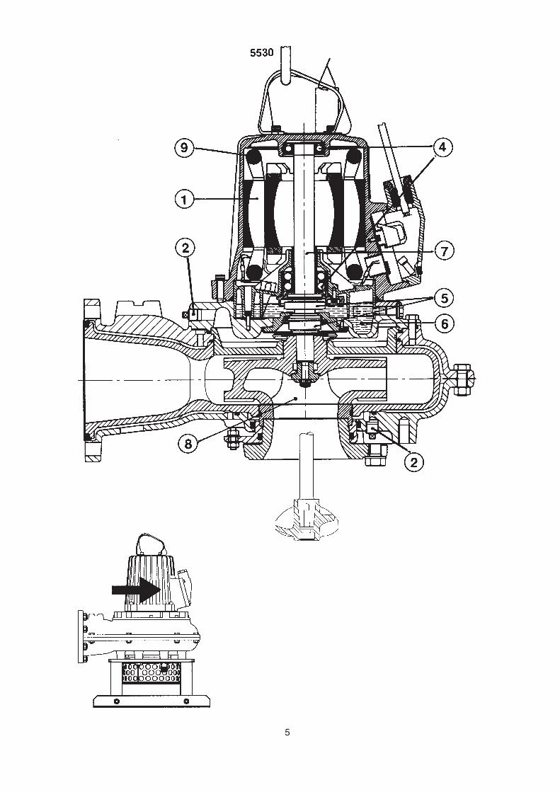
5530 and 5540 are submersible, electric motor-drivenpumps.
Design
1. Motor
Squirrel-cage 3-phase induction motor for 50 Hz or60 Hz.
The motor is started by means of direct on-line orstar-delta start.
The motor can be run continuously or intermittentlywith a maximum of 15 evenly spaced starts per hour.
Flygt motors are tested in accordance with IEC 34-1.
The stator is insulated in accordance with class F(155°C, 310°F). The motor is designed to supply itsrated output at ± 5 % variation of the rated voltage.Without overheating the motor, ± 10 % variation of therated voltage can be accepted provided that the motordoes not run continuously at full load. The motor isdesigned to operate with a voltage imbalance of up to2 % between the phases.
2. Flushing
External flushing of the outer seal can be connected toone of the holes. The other holes must then beplugged (1/2″ thread must be cut). Flow 1—3 l/minand a pressure of 5 m + shut-off head.
For more information, contact your nearest Flygtrepresentative.
3. Cooling
The motor is cooled by the surrounding liquid. Thepump must work fully submerged under full loadconditions otherwise external cooling must be used.Minimum flow of the external cooling water: 18 l/min.The 5530.181 is not available with external cooling.
4. Bearings
The pump bearings are designed for at least 50 000hours of operation.
The support bearing of the rotor consists of a singleball bearing for 5530 and a roller bearing for 5540.
The main bearing of the rotor consists of a two rowangular contact ball bearing.
5. Shaft seals
The pump has two mechanical seals with extremelywear-resistant seal surfaces.
Material: Inner seal: tungsten carbide—tungstencarbide.
Outer seal: tungsten carbide—tungsten carbide.
6. Oil casing
The oil lubricates and cools the seals and acts as abuffer between the pump casing and the electricmotor.
Pressure build-up within the oil casing is reduced bymeans of a built-in air volume.
7. Shaft
The shaft is delivered with the rotor as an integral part.
Shaft material: stainless steel.
8. Impellers
The pump is available with a shrouded three-channeltype of high crome alloyed white cast iron (HC).Throughlet is 40 mm.
9. Monitoring equipment
Three thermistors, connected in series, are incorpo-rated in the stator.
The resistance of the thermistor changes at 130°C(266°F) (reference temperature).
A platinum transducer (Pt 100) per phase, registersthe winding temperature.
The stator incorporates three thermal switchesconnected in series.
The thermal protectors: open at 125°C (260°F).
The thermal switches of the warm liquid version shallnot be connected when the liquid temperature isabove 40°C (105°F).
The monitoring equipment shall be of a design thatmakes automatic restart impossible.
The pump is available with leakage sensors forsensing the presence of any water in the oil and/orstator housing.
See also "Electrical connections" and separateinstructions for starter equipment/monitoring unit.
10. Wear parts
— Impeller
— Wear lining
— Wear ring
— Wear cover
— Suction cover
— Trimming flange
— Pumping housing
5

6
Performance curves
4XX = curve numbers
Each pump is tested in accordance with ISO 2548 class C standard.
= best operating point. * Extra power draw for the agitatorP = 0.7 kW (50 Hz), P = 1.2 kW (60 Hz)

7
A B C D E F G
5530.181 1184 (46 5/8) 835 (33) 231 (9 1/2) 278 (11) 220 (8 5/8) 280 (11) 110 (4 5/16)5540.181 1184 (46 5/8) 835 (33) 231 (9 1/2) 278 (11) 220 (8 5/8) 280 (11) 110 (4 5/16)
H J K L N O P
5530.181 109 (4 5/16) Ø20 (25/32) 55 (2 5/32) 340 (13 3/8) 360 (14 1/8) 500 (19 1/2) 395 (15 1/2)5540.181 109 (4 5/16) Ø20 (25/32) 55 (2 5/32) 340 (13 3/8) 595 (23 1/2) 500 (19 1/2) 395 (15 1/2)
Q R S T U W X
5530.181 85 (3 3/8) 495 (19 1/2) 550 (21 1/2) 116 (4 9/16) 284 (11 1/8) 880 (34 5/8) 768 (30 1/4)5540.181 85 (3 3/8) 495 (19 1/2) 550 (21 1/2) 116 (4 9/16) 284 (11 1/8) 1140 (44 7/8) 1028 (40 1/2)
Y
5530.181 85 (3 3/8)5540.181 85 (3 3/8)
HP All dimensions are in mm (in).
Q R
S
U T
X W NM
IN L
EV
EL
L
Y
O P
DN 150(6")
K
A
B
CD
EG
F
J (4x) H

8
A B C D E F G
5530.181 1031 (41) 632 (25) 382 (15) 687 (27) 1000 (40) 1079 (42 1/2) 615 (24)5540.181 1031 (41) 632 (25) 382 (15) 952 (37 1/2) 1175 (37 1/4) 1079 (42 1/2) 615 (24)
H J K L M N O
5530.181 365 (14 1/2) Ø23 (29/32) Ø150 (6) Ø240 (9 7/16) 600 (23 1/2) 231 (9 1/2) 278 (11)5540.181 365 (14 1/2) Ø23 (29/32) Ø150 (6) Ø240 (9 7/16) 600 (23 1/2) 231 (9 1/2) 278 (11)
P
5530.181 252 (10)5540.181 252 (10)
HS All dimensions are in mm (in).
M
M
BC
A
K
F
DE
GH
LK
J (8X)
22.5°45°
P
ON
9
A B C D E F G
5540.181 382 (15) 142 (55/8) 952 (371/2) 1175 (46) 250 (97/8) Ø150 (6) 392 (151/2)
H J K L M N O
5540.181 345 (135/8) Ø16 (5/8) 422 (165/8) 45 (13/4) 252 (10) 231 (9 1/2) 278 (11)
P Q R S T
5540.181 500 (20) 600 (231/2) 18 × 54 (11/16 × 21/8) Ø240 (97/16) Ø340 (133/8)
HT All dimensions are in mm (in).

10
A B C D E F G
5540.181 265 (107/16) 720 281/2) 1100 (431/4) 235 (91/4) Ø18 (45/64) 28 (17/64) 680 (263/4)
H J K L M N O
5540.181 1500 (59) 130 (51/8) Ø240 (97/16) Ø150 (6) Ø815 (32) 615 (24) 35 (13/8)
P
5540.181 Ø23 (29/32)
HS All dimensions are in mm (in).


5530.181/5540.181.04.06. Eng. 0.5M. 03.00 © ITT FLYGT AB 891818
Prin
ted
in S
wed
en K
T 2
0028
4