fmb fixed angle scraper - monroe truck equipment · fmb fixed angle scraper installation and parts...
TRANSCRIPT

FMB FIXED ANGLE SCRAPERInstallation and Parts Manual
0505098410/12/00
MONROE SNOW & ICE CONTROLA Division of Monroe Truck Equipment
1051 W. 7th StreetMonroe, WI 53566
Phone: 608-328-8127Fax: 608-329-8488


1
TABLE OF CONTENTS
SAFETY INSTRUCTIONS Page 2
MAINTENANCE INSTRUCTIONS Page 3
INSTALLATION INSTRUCTIONS Page 4-5
INSTALLATION DIAGRAMS Page 6-7
GENERAL INFORMATION Page 8
TORQUE CHART Page 8
HOW TO ORDER PARTS Page 9
RETURN POLICY Page 9
REPLACEMENT PARTS Page 10-18
WARRANTY INFORMATION Page 19

2
SAFETY INSTRUCTIONS
• Read all installation, safety and maintenance instructions completely before operating this equipment.
• Keep all personnel clear of moving parts while scraper is being operated.
• Lower the scraper blade to full down position, apply emergency brakeand stop engine before leaving the vehicle to inspect scraper.
• Do not operate truck in reverse with scraper blade in down position!
• Do not operate a scraper in need of maintenance! Repair immediately!
• While operating this equipment use common sense, use caution, be alert and be safety-conscious.
"IF IT CAN'T BE DONE SAFELY, DON'T DO IT!"Monroe Truck Equipment safety slogan

3
MAINTENANCE INSTRUCTIONSIn Season:
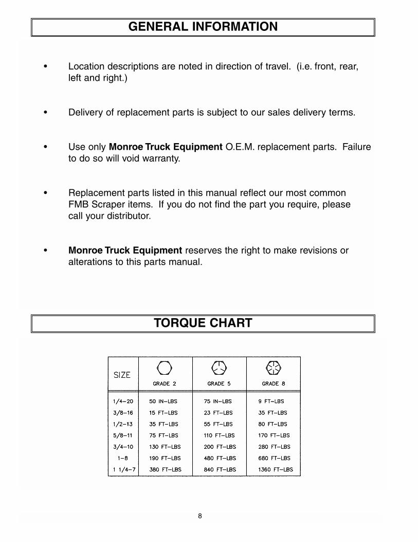
• Check for loose bolts and nuts daily, and re-torque before use. (Failure to inspect equipment on a daily basis may seriously affect safety and/or efficiency.)
• Lubricate all grease fittings every ten hours of normal use and more frequently under heavy use. (See diagram below for locations.)
• Check all hydraulic fittings for tightness on a regular basis.
• Check cutting edge for wear. Do not let cutting edge wear closer than 1⁄2" to 3⁄8" from moldboard.
• Due to the nature of use and environment this scraper is operating in, damage and wear may occur at anytime. Therefore, Monroe Truck Equipmentrecommends the end user establish and follow a daily inspection routine before using this scraper.
Off Season: (If Applicable)
• Use care when disconnecting hydraulic lines to assure that no dirt or foreign objects enter the hydraulic system. Use caps to cover hydraulic hose fittings and insert plugs into hydraulic ports.
• Hydraulic cylinders should be fully retracted when stored during the off season to prevent damage or corrosion. The remaining exposed shaft surface should be coated with a thick grease to prevent corrosion, which must be removed before returning to regular service.
• Check mounting bolts for wear and/or damaged threads and replace before re-mounting.
* **
**
* Location of grease fittings
**
* * * * *
* * * *
** *
* *
4
1. Clear the truck frame for mounting space necessary for scraper. You will need approximatly 24" of ground clearance for the entire area where the moldboard is
installed, and 3" clearance above the mounting plate.
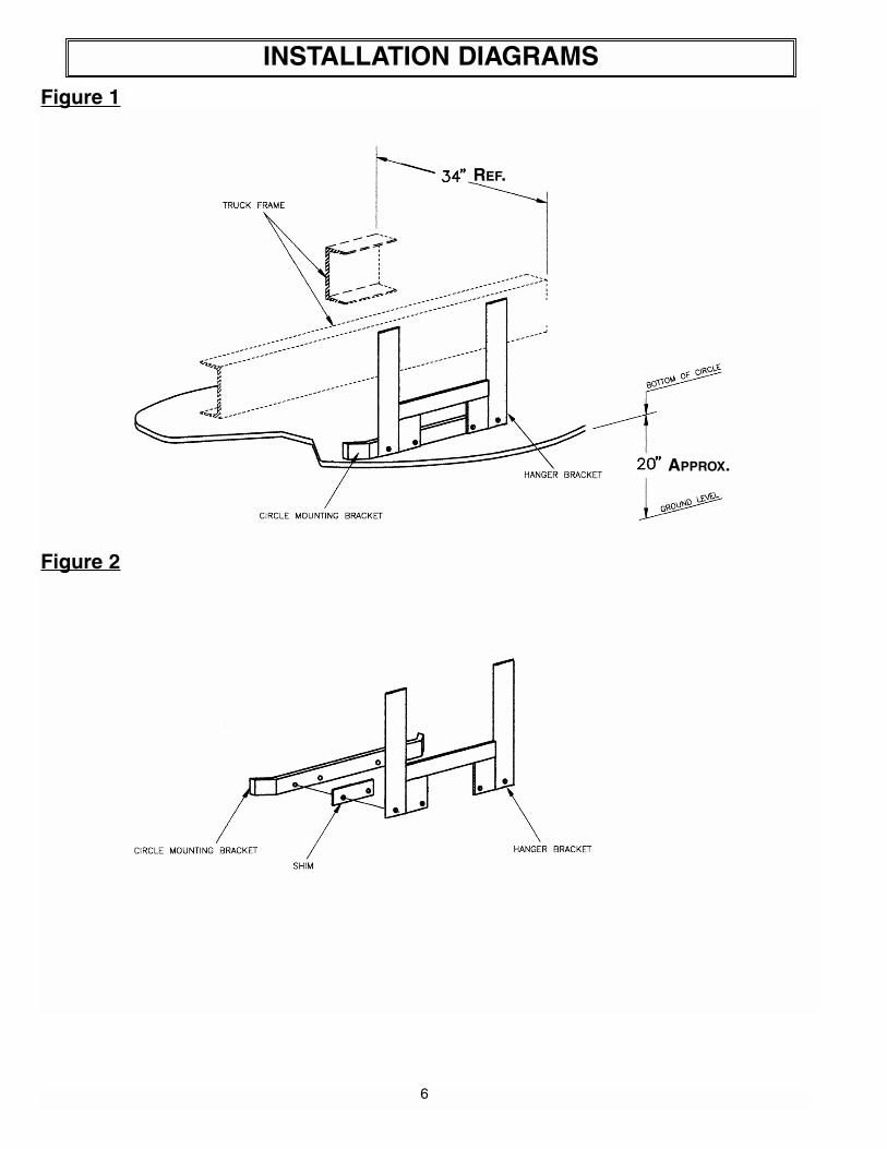
2. Slide the assembled circle under the truck and raise it into position. The distance from the bottom of the circle assembly to the ground should be approximately 20" (Figure 1). Be sure to square it off the truck frame, not the ground, as some truck frames are not parallel to the ground. ✔✔ Stay clear of area beneath circle until it
is safely and securely supported. Use Caution!
3. Move the circle hanger brackets into position. Note: The mounting brackets on the circle assembly for the hanger brackets are spaced at 34". Any frame width more than 34" will require the shims we provide. These shims are to be installed between the mounting bracket on the circle assembly and the hanger brackets (Figure 2).
4. Bolt the hanger brackets (and shims if needed) onto the circle mounting bracket.
5. Locate the hanger brackets on the frame in the proper position for the length of themoldboard you have (Figure 3).
6. Check all measurements to make sure scraper is located correctly. Note: Be sure to square circle assembly off the frame and not off the ground!
7. Drill and bolt the circle hangers into place.
NOTICE: This "Safety Check" ✔✔ symbol is a reminder to follow all safetymessages and precautions involved when installing or operating the FMBScraper. It means to be CAREFUL, ALERT and SAFETY CONSCIOUS!!!
INSTALLATION INSTRUCTIONS
5
8. Raise the hangerboard/moldboard assembly into place. Bolt the circle clamps in place, and install the center bolt. Tighten the center bolt until the hangerboard/ moldboard assembly swings freely through its entire arc. Install the cotter pin through the castellated nut. Warning: It is very important that the hangerboard/ moldboard assembly swings freely through its entire arc. If everything is mounted level and square, this is easily achieved. If there is a slight problem, a small amount of adjustment in most bolt holes is available. ✔✔ Stay clear of area beneath hangerboard/moldboard assembly until it is safely and securely supported. Use Caution!
9. After everything is installed and adjusted so that the hangerboard/moldboard assembly swings freely, install the swing cylinder(s) and plumb (Figure 4).Fasten the rear portion of the cylinder support bracket to the frame or a cross-member. (2 straps and a gusset, tack-welded together, are furnished.)
The proper valve for the power angle cylinder is a three position, four-way valve, which requires a hold position in neutral. A mechanical lock system is required to prevent cylinder damage. The valve for the curl or blade lift is also a three position, four-way.
Operate all the functions on the scraper, check for oil leaks. ✔✔ Stay clear of area beneath and near hangerboard/moldboard assembly while performing these operating tests. Use Caution!
CYLINDER OPERATING SAFETY PROCEDURES
✔✔ Operating pressure on the down side of the curl or raise/lower cylinders should not exceed 400 psi. The relief valve we furnish is factory preset. It must be installed on the down side of all scrapers. Changing the pressure may cause damage to the cylinder, possible injury, and will void the warranty.
✔✔ System pressure should not exceed 1000 psi for the power reverse cylinder(s) or 1850 psi for the upside of the curl cylinders. High pressure systems require additional relief valves (not furnished). Exceeding these pressures may cause damage to the cylinder(s), possible injury, and will void the warranty.
These mounting instructions are intended as a guide to aid you in the installation of your MonroeScraper. All dimensions noted in the instructions are approximate and may vary due to: make andmodel of chassis, tire size, type of suspension, spring deflection, customer preference, and interfer-ence caused by immovable attachments such as a transfer case. Ideally, the scraper should bemounted to get full usage of the cutting edge without wearing into the moldboard. Monroe TruckEquipment assumes no responsibility for improper installation, unless installed at an MTE location.Mounting location should be discussed by the end-user and the installer prior to installation in orderto achieve the best possible installation.
INSTALLATION INSTRUCTIONS
6
INSTALLATION DIAGRAMS
Figure 1
Figure 2
REF.
APPROX.

7
INSTALLATION DIAGRAMS
Figure 3
Figure 4
ACTUATING CYLINDERS 2 REVERSING CYLINDERS 1 REVERSING CYLINDER
8
GENERAL INFORMATION
• Location descriptions are noted in direction of travel. (i.e. front, rear, left and right.)
• Delivery of replacement parts is subject to our sales delivery terms.
• Use only Monroe Truck Equipment O.E.M. replacement parts. Failure to do so will void warranty.
• Replacement parts listed in this manual reflect our most common FMB Scraper items. If you do not find the part you require, please call your distributor.
• Monroe Truck Equipment reserves the right to make revisions or alterations to this parts manual.
TORQUE CHART

9
HOW TO ORDER PARTS
To order or inquire about replacement parts, please contact the distributor orstore that the product was purchased through. To speed the information flow, please have the following information ready:
• Model Number
• Serial Number
• Part Number and/or description as per the parts manual
• Quantity needed
For further information about Monroe Truck Equipment replacement parts, please call 800-880-0109 and ask for Snow & Ice Parts Sales.
RETURN POLICY
Merchandise returned to Monroe Truck Equipment must have a Warranty Service Request (WSR) form filled out completely and signed by authorized personnel. To get your WSR form, call 800-880-0109. For whole goods ask for Snow & Ice Sales. For replacement parts, ask for Snow & Ice Parts Sales. All returned items are subject to a 15% restocking fee and must be sent freight prepaid!

10
FIXED ANGLED SCRAPER, FMB 10, 3⁄4”X 10”, MS
ITEM QTY PART # DESCRIPTION
1 1 00066291 Hangerboard Assembly, FMB 10,3⁄4” x 10” (See page 11)
2 1 00066292 Braket Weldment, Mounting3 2 00039276 Hanger Bracket 4 1 00066294 Mounting Kit (See page 17)
2
3

11
00066291 HANGERBOARD MOLDBOARD ASSEMBLY
ITEM QTY PART # DESCRIPTION
1 1 -------- Hangerboard Kit, FMB (see page 12-13)
2 1 -------- Moldboard Kit, FMB 10, 3⁄4”X10”(see page 15)
3 2 05002568 Cylinder, 3X4 DA (see page 18)
4 1 -------- Cutting Edge Kit, 10’ (see page 16)

12
2820
3178 292221 31
16
15149 17
363534 372718
10
33
26 30 24 30
11
45263
12
25 31
1319 28
13023
HANGERBOARD

13
HANGERBOARD
ITEM QTY PART # DESCRIPTION
1 1 00066284 Hangerboard Weldment2 2 00060665 Outer Springs Bracket, RH3 2 00060666 Outer Springs Bracket, LH4 2 00060671 Inner Springs Bracket, RH5 2 00060672 Inner Springs Bracket, LH6 4 00060674 FMB Spring Assembly (see page 14)
7 4 00060703 Pin, 11⁄2”X43⁄4”8 4 00060678 Spring Attachment Bracket9 2 00041861 Linkage Weldment, Outer FMB10 2 00060660 Linkage Weldment, Inner FMB11 1 00060683 Bracket, RH Linkage12 1 00060684 Bracket, LH Linkage13 4 00060087 Linkage, Moldboard14 2 05022000 Pin, 1”X31⁄2”, Button Head Zinc15 2 05022100 Pin, 3⁄16”X11⁄2”, Cotter16 2 00060658 Attachment, Linkage17 4 00060701 Rod, 11⁄2” DIA X 8”18 8 05010626 Bolt, 5⁄16-18”X3”, G8, HHCS, Zinc19 4 05010693 Bolt, 1⁄2-13”X2”, G8, HHCS, Zinc20 4 05010707 Bolt, 1⁄2-13”X7”, G8, HHCS, Zinc21 4 05014703 Bolt, 5⁄8-11”X21⁄2, G8, FSH, Plain22 4 05014553 Bolt, 5⁄8-11”X3”, G8, DH, Plain23 4 05010766 Bolt, 3⁄4-10”X21⁄2”, G8, HHCS, Zinc 24 2 05014710 Bolt, 3⁄4-10”X21⁄2”, G8, FSH, Plain25 4 05010768 Bolt, 3⁄4-10”X3”, G8, HHCS, Zinc26 6 05010770 Bolt, 3⁄4-10”X31⁄2”, G8, HHCS, Zinc27 8 05020909 Nut, 5⁄16-18”, GC, Toplock, C&W28 8 05020847 Nut, 1⁄2-13”, GC, Toplock, C&W29 8 05020270 Nut, 5⁄8-11”, G8, Hex, Zinc30 16 05020849 Nut, 3⁄4-10”, GC, Toplock, C&W31 8 05021383 Washer, 5⁄8”, Heavy Spring Lock, Zinc32 4 05022007 Pin, 1⁄4”X11⁄2”, Cotter33 2 05037158 Tee Adapter, 3⁄8”, Female (all three)34 4 05037075 Elbow, 45 DEG, 3⁄8”, Black Pipe35 4 05037073 Hose Assembly, 3⁄8”, 2-Wire, 22OAL
14
2
4
5
31
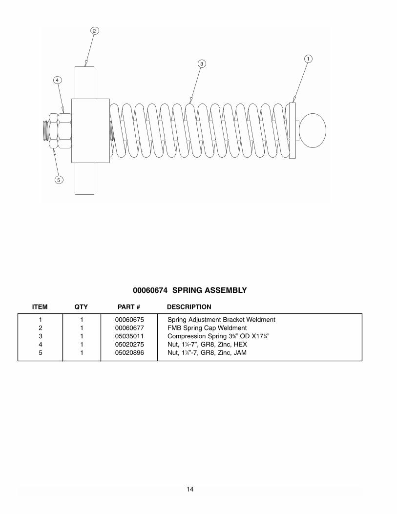
00060674 SPRING ASSEMBLY
ITEM QTY PART # DESCRIPTION
1 1 00060675 Spring Adjustment Bracket Weldment2 1 00060677 FMB Spring Cap Weldment3 1 05035011 Compression Spring 33⁄8” OD X171⁄4”4 1 05020275 Nut, 11⁄4-7”, GR8, Zinc, HEX5 1 05020896 Nut, 11⁄4”-7, GR8, Zinc, JAM

15
2
4 6 7
38 5 12
1
1311109
MOLDBOARD KIT, 3⁄4”X10”, RH
ITEM QTY PART # DESCRIPTION
1 1 00066297 Moldboard Weldment, 10’, Scrapper, FMB, Taper2 2 00041852 Support, Upper Moldboard Hinge3 2 00041853 Support, Lower Moldboard Hinge4 2 00045822 Cap, Upper Moldboard Hinge5 2 00060670 Cap6 2 00060699 Rod, 13⁄4” DIA X 1⁄4”7 2 00041863 Round Tube, 11⁄4” OD x 7⁄32”W X27⁄8”8 1 00060680 Rod, 11⁄2”DIA x103”9 16 05014549 Bolt, 5⁄8-11”X2” G8, DH, Plain10 16 05020837 Nut, 5⁄8-11”, GC, Toplock, C&W11 16 05021017 Washer, 5⁄8” Flat, SAE, Hard, F/W12 2 05050003 Grease Fitting, 1⁄8”, NPT, Straight13 1 05032013 Moldboard, 3⁄4”X10’

16
CUTTING EDGE KIT, 10’, 5⁄8”X6”,DBC
ITEM QTY PART # DESCRIPTION
1 2 05031000 Cutting Edge, 5⁄8”x6”x5’, DBC2 05031113 Cutting Edge, 1⁄2”X6”X5’, DBC
2 14 05014551 Bolt,5⁄8-11”X21⁄2”, G8, Domehead, Plain3 14 06020270 Nut, 5⁄8-11”, G8, HEX, Zinc
1
2 3 4
17
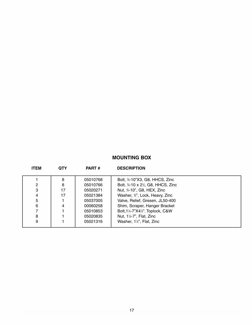
MOUNTING BOX
ITEM QTY PART # DESCRIPTION
1 8 05010768 Bolt, 3⁄4-10”X3, G8, HHCS, Zinc2 8 05010766 Bolt, 3⁄4-10 x 21⁄2, G8, HHCS, Zinc3 17 05020271 Nut, 3⁄4-10”, G8, HEX, Zinc4 17 05021384 Washer, 3⁄4”, Lock, Heavy, Zinc5 1 05037005 Valve, Relief, Gresen, JL50-4006 4 00060258 Shim, Scraper, Hanger Bracket7 1 05010853 Bolt,11⁄4-7”X41⁄2”. Toplock, C&W8 1 05020835 Nut, 11⁄4-7”, Flat, Zinc9 1 05021316 Washer, 11⁄4”, Flat, Zinc

18
ITEM QTY PART NUMBER DESCRIPTION
1 1 05001001 NUT, 1-14, LOCK
2 1 05002672 PISTON
3 1 05002022 WASHER, PISTON
4 1 05002684 CASE WELDMENT
5 1 05002685 ROD WELDMENT
6 1 05002686 SPACER, 11⁄8"
7 1 05002676 HEAD
8 1 05002555 CAP, THREAD
9 1 05002648 SCREW, 1⁄4-20, SET
1 05002677 SEAL KIT
05002568 CYLINDER, 3X4, DA, CURL FMB
19
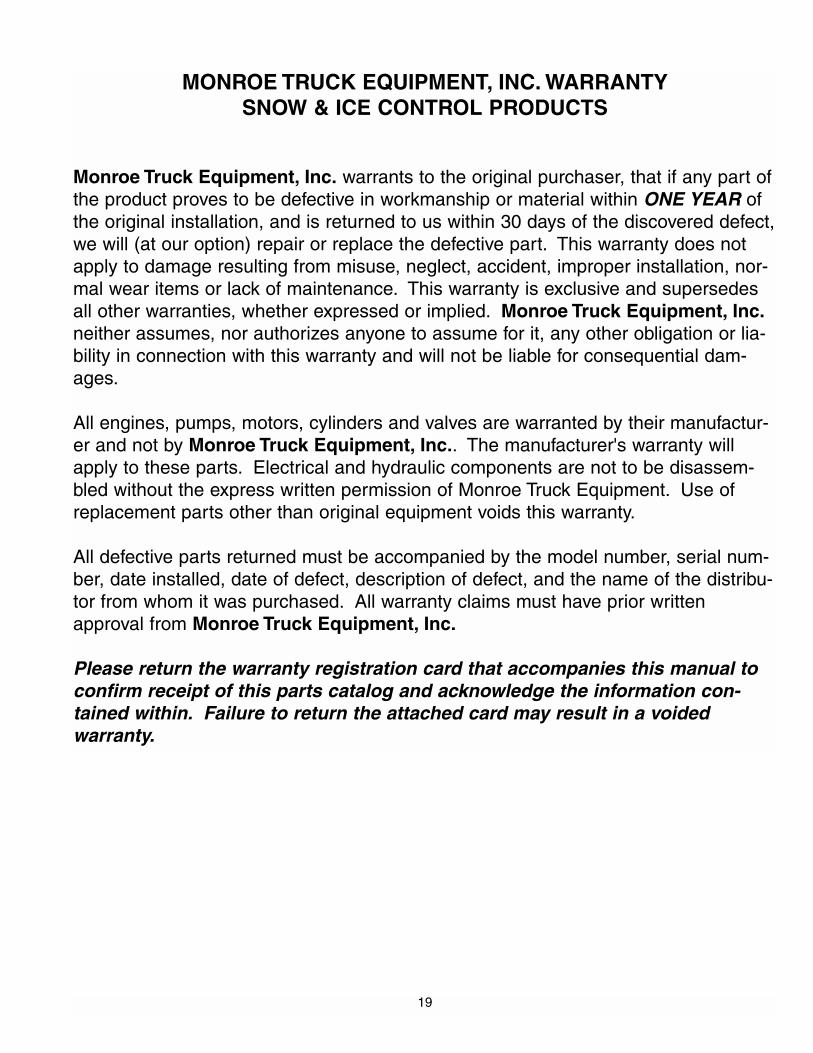
MONROE TRUCK EQUIPMENT, INC. WARRANTYSNOW & ICE CONTROL PRODUCTS
Monroe Truck Equipment, Inc. warrants to the original purchaser, that if any part ofthe product proves to be defective in workmanship or material within ONE YEAR ofthe original installation, and is returned to us within 30 days of the discovered defect,we will (at our option) repair or replace the defective part. This warranty does notapply to damage resulting from misuse, neglect, accident, improper installation, nor-mal wear items or lack of maintenance. This warranty is exclusive and supersedesall other warranties, whether expressed or implied. Monroe Truck Equipment, Inc.neither assumes, nor authorizes anyone to assume for it, any other obligation or lia-bility in connection with this warranty and will not be liable for consequential dam-ages.
All engines, pumps, motors, cylinders and valves are warranted by their manufactur-er and not by Monroe Truck Equipment, Inc.. The manufacturer's warranty willapply to these parts. Electrical and hydraulic components are not to be disassem-bled without the express written permission of Monroe Truck Equipment. Use ofreplacement parts other than original equipment voids this warranty.
All defective parts returned must be accompanied by the model number, serial num-ber, date installed, date of defect, description of defect, and the name of the distribu-tor from whom it was purchased. All warranty claims must have prior writtenapproval from Monroe Truck Equipment, Inc.
Please return the warranty registration card that accompanies this manual toconfirm receipt of this parts catalog and acknowledge the information con-tained within. Failure to return the attached card may result in a voidedwarranty.

20
Page 1 of 2 Parts Warranty Policy 1-1
1051 West 7th Street Monroe, WI 53566
608-328-8127 ~ Fax: 608-328-4278
GLOBAL SOLUTION ARMORED VEHICLES ~ SPORT TRUCK CONVERSIONS MUNICIPAL SNOW & ICE CONTROL ~ FIRE APPARATUS
PICKUP TRUCK ACCESSORIES ~ TRUCK EQUIPMENT/MODIFICATIONS
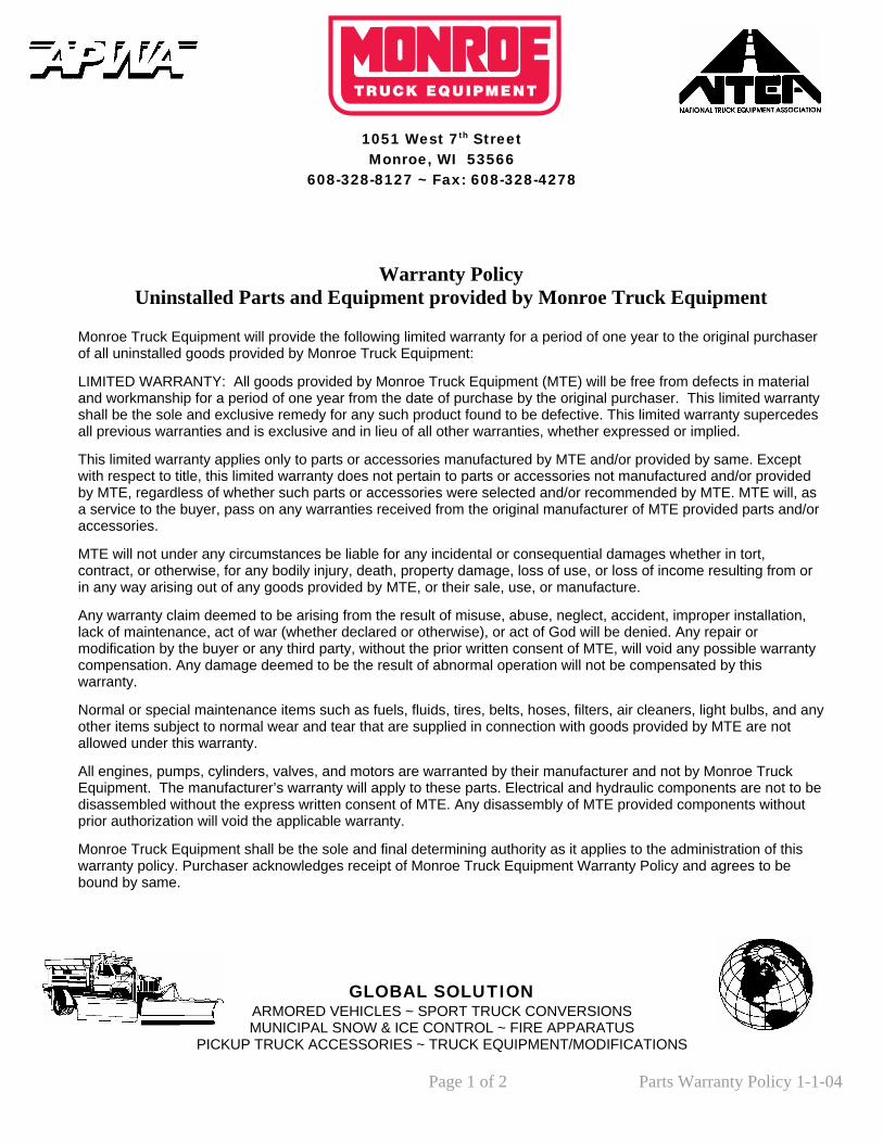
Warranty Policy
Uninstalled Parts and Equipment provided by Monroe Truck Equipment
Monroe Truck Equipment will provide the following limited warranty for a period of one year to the original purchaserof all uninstalled goods provided by Monroe Truck Equipment:
LIMITED WARRANTY: All goods provided by Monroe Truck Equipment (MTE) will be free from defects in material and workmanship for a period of one year from the date of purchase by the original purchaser. This limited warrantyshall be the sole and exclusive remedy for any such product found to be defective. This limited warranty supercedesall previous warranties and is exclusive and in lieu of all other warranties, whether expressed or implied.
This limited warranty applies only to parts or accessories manufactured by MTE and/or provided by same. Except with respect to title, this limited warranty does not pertain to parts or accessories not manufactured and/or provided by MTE, regardless of whether such parts or accessories were selected and/or recommended by MTE. MTE will, asa service to the buyer, pass on any warranties received from the original manufacturer of MTE provided parts and/oraccessories.
MTE will not under any circumstances be liable for any incidental or consequential damages whether in tort, contract, or otherwise, for any bodily injury, death, property damage, loss of use, or loss of income resulting from or in any way arising out of any goods provided by MTE, or their sale, use, or manufacture.
Any warranty claim deemed to be arising from the result of misuse, abuse, neglect, accident, improper installation, lack of maintenance, act of war (whether declared or otherwise), or act of God will be denied. Any repair or modification by the buyer or any third party, without the prior written consent of MTE, will void any possible warrantycompensation. Any damage deemed to be the result of abnormal operation will not be compensated by this warranty.
Normal or special maintenance items such as fuels, fluids, tires, belts, hoses, filters, air cleaners, light bulbs, and another items subject to normal wear and tear that are supplied in connection with goods provided by MTE are not allowed under this warranty.
All engines, pumps, cylinders, valves, and motors are warranted by their manufacturer and not by Monroe Truck Equipment. The manufacturer’s warranty will apply to these parts. Electrical and hydraulic components are not to bedisassembled without the express written consent of MTE. Any disassembly of MTE provided components without prior authorization will void the applicable warranty.
Monroe Truck Equipment shall be the sole and final determining authority as it applies to the administration of this warranty policy. Purchaser acknowledges receipt of Monroe Truck Equipment Warranty Policy and agrees to be bound by same.
y
-04

Page 2 of 2 Parts Warranty Policy 1-1-04
Any and all warranty claims must be forwarded to MTE within 10 days of defect discovery. A copy of the original Monroe Truck Equipment invoice as well as the manufacturer’s model number, serial number, and date of installation must accompany all correspondence regarding said claims. MTE will, at their option, choose whether to repair or replace the defective part unless otherwise specified by the original manufacturer of said part.
Procedures for Warranty Claims Notification For submission of any warranty claim please contact Monroe Truck Equipment – Warranty Department at 800-356-8134 The following documentation will be needed when you call for initial warranty authorization:
1. A copy of the original MTE invoice. 2. Make, Model, and VIN or Serial Number of the equipment involved. 3. Part number and serial number of the part in question. 4. A complete description of the problem.
The following must accompany any claim submitted to Monroe Truck Equipment:
1. Documented photographs of any physical damage. 2. Inspection notes by MTE personnel or MTE authorized 3rd party. 3. Authorization number issued by Monroe Truck Equipment – Warranty Department.
Defective parts must be returned to Monroe Truck Equipment (freight prepaid) within 30 days of issuance of Authorization Number. Monroe Truck Equipment reserves the right to void any warranty for failure to comply with Monroe Truck Equipment Warranty Policy.
This policy is effective January 1, 2004
