for upflow/horizontal & downflow induced draft gas...
TRANSCRIPT

92-24161-51-00
INSTALLATION INSTRUCTIONSFOR UPFLOW/HORIZONTAL & DOWNFLOW INDUCEDDRAFT GAS FURNACES(-)GPQ UPFLOW/HORIZONTAL SERIES(-)GLQ DOWNFLOW SERIES
U.L. recognized fuel gas and CO (Carbon Monoxide) detectors are recommended inall applications, and their installation should be in accordance with the manufacturer’srecommendations and/or local laws, rules, regulations, or customs.
2
Before beginning any troubleshooting procedure, complete the following installation checklist. A furnace malfunction issometimes caused by an improper installation. By completing this checklist, the problem may be found and corrected. Makecopies of the checklist and complete one for every Low Profile Furnace service call for your records.
INSTALLATION CHECKLIST(Refer to this manual for specifics.)
GAS SUPPLY
Adequate pipe size
No gas leaks
Proper supply and manifold gas pressure (check with an accurate U-tube manometer with the furnace and all other gasappliances operating.)
ELECTRICAL
Correct thermostat and subbase Thermostat model Subbase model
Correct thermostat mode and setting
Correct line supply voltage
Correct power supply polarity is required with electronic ignition
Correct furnace ground to electrical panel
DC microamp (μA) flame signal (hot surface ignition units)
Correct control voltage
Measure and set heat anticipator amperage
Air conditioning low voltage wires connected to terminals “Y” “C” - not with wire nuts
VENTING
Correct vent pipe diameter and length (according to CSA tables) Vent connection size
Correct venting material (according to CSA tables)
Correct lining for masonry chimneys
Adequate clearance from combustibles
Proper negative pressure reading in the vent
Vent pipe secured to induced draft blower housing
COMBUSTION AIR
Proper source of combustion air
Correct combustion air opening size
Optional attic combustion air pull
Non-attic combustion air pull
FURNACE INSTALLATION
Adequate clearance from combustibles
Adequate clearance for service
Proper air temperature rise (See furnace rating plate)
External static pressure inches w.c.
Correct filter(s)
Correct cooling coil or accessories (if equipped)
Adequate supply and return air ducting Return Air Duct Size Supply Air Duct Size
Air ducts sealed to prevent leakage
33
IMPORTANT: TO INSURE PROPER INSTALLATION AND OPERATION OFTHIS PRODUCT, COMPLETELY READ ALL INSTRUCTIONS PRIOR TOATTEMPTING TO ASSEMBLE, INSTALL, OPERATE, MAINTAIN OR REPAIRTHIS PRODUCT. UPON UNPACKING OF THE FURNACE, INSPECT ALLPARTS FOR DAMAGE PRIOR TO INSTALLATION AND START-UP.
CONTENTS
Installation Check List ..............................................................................................2
Safety Information ....................................................................................................4
General Information..................................................................................................5
Location Requirements and Considerations ............................................................5
Combustion and Ventilation Air..............................................................................10
Vent Pipe Installation..............................................................................................14
Gas Supply and Piping...........................................................................................17
Electrical Wiring......................................................................................................21
Thermostat .............................................................................................................21
Accessories ............................................................................................................22
Furnace Twinning...................................................................................................22
High Altitude Installations .......................................................................................25
Start-Up Procedure ................................................................................................28
Air Flow...................................................................................................................31
Blower Performance Data ......................................................................................32
Safety Features ......................................................................................................33
Maintenance...........................................................................................................34
Troubleshooting......................................................................................................37
Wiring Diagram.......................................................................................................39
Important: All manufacturer productsmeet current Federal OSHA Guidelinesfor safety. California Proposition 65warnings are required for certainproducts, which are not covered by theOSHA standards.
California's Proposition 65 requireswarnings for products sold in Californiathat contain, or produce, any of over600 listed chemicals known to the Stateof California to cause cancer or birthdefects such as fiberglass insulation,lead in brass, and combustion productsfrom natural gas.
All “new equipment” shipped for sale inCalifornia will have labels stating thatthe product contains and/or producesProposition 65 chemicals. Although wehave not changed our processes,having the same label on all ourproducts facilitates manufacturing andshipping. We cannot always know“when, or if” products will be sold in theCalifornia market.
You may receive inquiries fromcustomers about chemicals found in, orproduced by, some of our heating andair-conditioning equipment, or found innatural gas used with some of ourproducts. Listed below are thosechemicals and substances commonlyassociated with similar equipment inour industry and other manufacturers.
• Glass Wool (Fiberglass) Insulation• Carbon Monoxide (CO)• Formaldehyde• Benzene
More details are available at theWebsites for OSHA (OccupationalSafety and Health Administration), atwww.osha.gov and the State ofCalifornia's OEHHA (Office ofEnvironmental Health HazardAssessment), at www.oehha.org.Consumer education is important sincethe chemicals and substances on thelist are found in our daily lives. Mostconsumers are aware that productspresent safety and health risks, whenimproperly used, handled andmaintained.

4
USE ONLY WITH TYPE OF GASAPPROVED FOR THIS FURNACE.REFER TO THE FURNACE RATINGPLATE.
INSTALL THIS FURNACE ONLY INA LOCATION AND POSITION ASSPECIFIED IN THE LOCATIONREQUIREMENTS ANDCONSIDERATIONS SECTION OFTHESE INSTRUCTIONS.
PROVIDE ADEQUATECOMBUSTION AND VENTILATIONAIR TO THE FURNACE SPACE ASSPECIFIED IN THE VENTINGSECTION OF THESEINSTRUCTIONS.
COMBUSTION PRODUCTS MUSTBE DISCHARGED OUTDOORS.CONNECT THIS FURNACE TO ANAPPROVED VENT SYSTEM ONLY,AS SPECIFIED IN VENT PIPEINSTALLATION SECTION OFTHESE INSTRUCTIONS.
THE MANUFACTURER IS NOTRESPONSIBLE FOR EQUIPMENTTHAT IS MISMATCHED ORIMPROPERLY INSTALLED.
NEVER TEST FOR GAS LEAKSWITH AN OPEN FLAME. USE ACOMMERCIALLY AVAILABLESOAP SOLUTION MADESPECIFICALLY FOR THEDETECTION OF LEAKS TO CHECKALL CONNECTIONS, ASSPECIFIED IN GAS SUPPLY ANDPIPING SECTION OF THESEINSTRUCTIONS.
ALWAYS INSTALL FURNACE TOOPERATE WITHIN THEFURNACE'S INTENDEDTEMPERATURE-RISE RANGEWITH A DUCT SYSTEM WHICHHAS AN EXTERNAL STATICPRESSURE WITHIN THEALLOWABLE RANGE, ASSPECIFIED IN DUCTING SECTIONOF THESE INSTRUCTIONS. SEEALSO FURNACE RATING PLATE.
WHEN A FURNACE IS INSTALLEDSO THAT SUPPLY DUCTS CARRYAIR CIRCULATED BY THEFURNACE TO AREAS OUTSIDETHE SPACE CONTAINING THEFURNACE, THE RETURN AIRSHALL ALSO BE HANDLED BYDUCT(S) SEALED TO THEFURNACE CASING ANDTERMINATING OUTSIDE THESPACE CONTAINING THEFURNACE.
WHEN THIS FURNACE ISINSTALLED IN A RESIDENTIALGARAGE, IT MUST BE INSTALLEDSO THE BURNERS AND IGNITIONSOURCE ARE LOCATED NO LESSTHAN 18 INCHES ABOVE THEFLOOR. THIS IS TO REDUCE THERISK OF IGNITING FLAMMABLEVAPORS WHICH MAYBE PRESENT IN A GARAGE.ALSO, THE FURNACE MUST BELOCATED OR PROTECTED TOAVOID PHYSICAL DAMAGE BYVEHICLES. FAILURE TO FOLLOWTHESE WARNINGS CAN CAUSE AFIRE OR EXPLOSION, RESULTINGIN PROPERTY DAMAGE,PERSONAL INJURY OR DEATH.
USE OF THIS FURNACE ISALLOWED DURINGCONSTRUCTION IF THEFOLLOWING TEMPORARYINSTALLATION REQUIREMENTSARE MET. INSTALLATION MUSTCOMPLY WITH ALLINSTALLATION INSTRUCTIONSINCLUDING:
• PROPER VENT INSTALLATION;
• FURNACE OPERATING UNDERTHERMOSTATIC CONTROL;
• RETURN AIR DUCT SEALED TOTHE FURNACE;
• AIR FILTERS IN PLACE;
• SET FURNACE INPUT RATEAND TEMPERATURE RISE PERRATING PLATE MARKING;
• MEANS FOR PROVIDINGOUTDOOR AIR REQUIRED FORCOMBUSTION;
• RETURN AIR TEMPERATUREMAINTAINED BETWEEN 55°F(13°C) AND 80°F (27°C); AND
• CLEAN FURNACE, DUCT WORKAND COMPONENTS UPONSUBSTANTIAL COMPLETION OFTHE CONSTRUCTIONPROCESS, AND VERIFYFURNACE OPERATINGCONDITIONS INCLUDINGIGNITION, INPUT RATE,TEMPERATURE RISE ANDVENTING, ACCORDING TO THEINSTRUCTIONS.
! WARNING
! WARNING
! WARNING
! WARNING
! WARNING
! WARNING
! WARNING
! WARNING
! WARNING
! WARNING
SAFETY INFORMATION

5
GENERAL INFORMATION1. NOTE: This furnace is shipped with
heat exchanger support bracketsinstalled under the back of the heatexchanger. These may be removedbefore installation, but it is notrequired.
LOCATION
THIS FURNACE IS NOT APPROVEDFOR INSTALLATION IN A MOBILEHOME. DO NOT INSTALL THISFURNACE IN A MOBILE HOME.INSTALLATION IN A MOBILE HOMECOULD CAUSE FIRE, PROPERTYDAMAGE, PERSONAL INJURY ORDEATH.2. IMPORTANT: This furnace is not
approved or recommended forinstallation on its back, with accessdoors facing upwards.
3. This furnace is suitable forinstallation in buildings constructedon-site. This heating unit should becentralized with respect to the heatdistribution system as much aspracticable.
4. NOTE: These furnaces areapproved for installation in attics, as
well as alcoves, utility rooms,closets and crawlspaces.
5. IMPORTANT: Support this unit wheninstalled. For attic or crawl spaceinstallation, horizontal furnaces maybe installed on combustible woodflooring or by using support brackets.See Figure 1.
6. IMPORTANT: If installing in a utilityroom, be sure the door is wideenough to:a. allow the largest part of the
furnace to pass; orb. allow any other appliance (such
as a water heater) to pass.
The (-)GPQ/(-)GLQ series furnaces aredesign certified by CSA for use withnatural and propane gases as follows:
As a Category I furnace, it may bevented vertically with type B-1 ventpipe and also may be commonvented as described in theseinstructions.
This furnace should be installed inaccordance with the American NationalStandard Z223.1 - latest edition bookletentitled “National Fuel Gas Code”(NFPA 54) (in Canada, CSA B149.1and .2 Installation Codes for gasburning appliances), and therequirements or codes of the local utilityor other authority having jurisdictionincluding local plumbing or waste watercodes.The National Appliance EnergyConservation Act (NAECA) of 1987states that any gas furnacemanufactured after January 1, 1992,must have a minimum Annual FuelUtilization Efficiency (AFUE) of 78%.The higher the AFUE percentage themore usable heat energy the consumergets for every dollar of fuel purchased.This is similar to the EPA's minimumgas mileage requirement forautomobiles. It gives the consumer arelatively easy way to make directefficiency comparisons betweendifferent furnace brands and styles.A high AFUE value, which translates
into a low operating cost, is not the onlyconcern that consumers have. Theyalso want a furnace with a reasonableinstalled cost. They want a furnace thatprovides them with comfort – their mainconcern. And they expect a furnace withexceptional reliability and longevity.Gas furnace manufacturers are alwaysstriving to provide consumers with thebest furnace value. The Low ProfileFurnace addresses all those consumerneeds. It gives exceptional efficiencywith a low installation cost. It deliversthe comfort the customer wants alongwith the reliability they expect.The key to all these customer benefits isthe furnace's heat exchanger. Thematerials used to construct the furnacein general and the heat exchanger inparticular make it a rugged, long lastingunit. The unique heat exchanger designprovides the customer with a furnaceonly 34 inches high. This gives theconsumer a unit easily installed inalmost every location that accepts allcustomary accessories.With the introduction of higher efficiencyfurnaces, special attention must be paidto the venting system. Only listedventing systems may be used as statedin the installation instructions and theNational Fuel Gas Code, ANSI Z223.1(NFPA 54), or the Canadian CAN/CGAB149.1 and B149.2 Installation Codesfor Gas Burning Appliances. Since
furnace technology and ventingrequirements are changing, awarenessof local, state, and federal codes andindustry changes is imperative.NOTE: Always perform a proper heatloss calculation before specifying thefurnace size. This ensures that thefurnace is sized to adequately,economically, heat the building andprovide the correct airflow for yourapplication.IMPORTANT: PROPERAPPLICATION, INSTALLATION ANDMAINTENANCE OF THIS FURNACEIS A MUST IF CONSUMERS ARE TORECEIVE THE FULL BENEFITS FORWHICH THEY HAVE PAID.Additional helpful publications availablefrom the “National Fire ProtectionAssociation” are: NFPA-90A –Installation of Air Conditioning andVentilating Systems 1985 or latestedition. NFPA-90B – Warm Air Heatingand Air Conditioning Systems 1984.These publications are available from:
National Fire Protection Association,Inc.
Batterymarch ParkQuincy, MA 02269CSA-INTERNATIONAL178 Rexdale Blvd.Etobicoke (Toronto), OntarioCanada M9W, 1R3
GENERAL INFORMATION
LOCATION REQUIREMENTS AND CONSIDERATIONS
WARNING!FIGURE 1HORIZONTAL FURNACE INSTALLED W/SUPPORT BRACKETS
ST-A0799-01
NOTE: Do not block furnaceaccess with support rods. Maintainclearances recommended in Figure 2.Allow enough space for proper servicemaintenance or replacement of the heatexchanger and blower assembly.
EXHAUSTVENT

6
CLE
AR
AN
CE
TO
CO
MB
US
TIB
LE M
AT
ER
IAL
(INC
HE
S)
UP
FLO
W/H
OR
IZO
NTA
L M
OD
ELS
TO
P
LEFT
SID
E
FRO
NT
RIG
HT
SID
E
ALT
ER
NA
TE
GA
S C
ON
NE
CT
ION
BO
TT
OM
RE
TU
RN
AIR
AIR
FLO
W
SU
PP
LYA
IR
2613
/16
265 /8
2411
/32
2411
/32
19/3
2
9 /16
247 /1
6
281 /1
6
265 /8
143 /8
111 /2
34
15 /8D
IA.
23
15
20D
7 /8D
IA.
7 /8D
IA.
19/3
219
/32
3 /4
143 /8
111 /2
11 /4
2317
/32
C
F
GA
S C
ON
NE
CT
ION
ELE
CT
RIC
AL
CO
NN
EC
TIO
N
OP
TIO
NA
L R
ET
UR
N A
IR C
UT
OU
T(E
ITH
ER
SID
E)
FO
R U
SE
WIT
HE
XT
ER
NA
L S
IDE
FIL
TE
R F
RA
ME
LOW
VO
LTA
GE
E
SIG
HT
GLA
SS
A B
FIGURE 2UPFLOW/HORIZONTAL DIMENSIONS
IMP
OR
TA
NT
: Thi
s fu
rnac
e is
not
app
rove
d or
rec
omm
ende
d fo
rin
stal
latio
n on
its
back
, with
acc
ess
door
s fa
cing
upw
ards
.
REDU
CED
CLEA
RANC
E (IN
.)
Mod
elA
BC
DE
FLe
ftRi
ght
Back
Top
Fron
tVe
ntSh
ip.
Side
Side
Wgt
s.
0514
1227/32
105 /8
➀11
1 /217 /8
04➁
01
36➂
85 lb
s.
0717
1 /216
11/32
123 /8
➀15
21 /20
3➁0
13
6➂10
5 lb
s.
10(A
)17
1 /216
11/32
123 /8
➀15
21 /20
3➁0
13
6➂11
5 lb
s.
10(B
)21
1927/32
141 /8
➀18
1 /221 /2
00
01
36➂
120
lbs.
1224
1 /223
11/32
157 /8
➀22
21 /20
00
13
6➂14
0 lb
s.
1524
1 /223
11/32
157 /8
➀22
21 /20
00
13
6➂15
0 lb
s.
➀M
ay re
quire
3”
to 4
” or
3”
or 5
” ad
apte
r.➁
May
be
0” w
ith ty
pe B
ven
t.➂
May
be
1” w
ith ty
pe B
ven
t.
241 /2
25.4
06
7
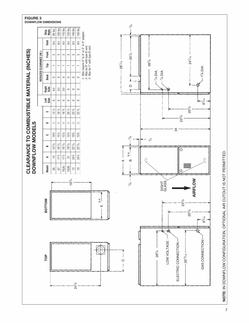
FIGURE 3DOWNFLOW DIMENSIONS
REDU
CED
CLEA
RANC
E (IN
.)
Mod
elA
BC
DE
Left
Righ
tBa
ckTo
pFr
ont
Vent
Ship
.Si
deSi
deW
gts.
0514
1227/32
103 /8
➀13
1 /80
4➁0
13
6➂85
lbs.
0717
1 /216
11/32
121 /8
➀16
5 /80
3➁0
13
6➂10
5 lb
s.
10(A
)17
1 /216
11/32
121 /8
➀16
5 /80
3➁0
13
6➂11
5 lb
s.
10(B
)21
1927/32
137 /8
➀20
1 /80
00
13
6➂12
0 lb
s.
1224
1 /223
11/32
155 /8
➀23
5 /80
00
13
6➂14
0 lb
s.
1524
1 /223
11/32
155 /8
➀23
5 /80
00
13
6➂15
0 lb
s.
TO
PB
OT
TO
M
241 /2
193 /4
CA B
D
LOW
VO
LTA
GE
GA
S C
ON
NE
CT
ION
ELE
CT
RIC
CO
NN
EC
TIO
N
ES
.A.
R.A
.
265 /8
2613
/16
63 /1620
3 /8
233 /8
5 /85 /8
3 /4
5 /8
34
233 /8
203 /8
63 /16
247 /1
6
265 /820
1 /8
281 /1
6
7 /8D
IA.
7 /8D
IA.
15 /8D
IA.
CLE
AR
AN
CE
TO
CO
MB
US
TIB
LE M
AT
ER
IAL
(INC
HE
S)
DO
WN
FLO
W M
OD
ELS
NO
TE
:IN
DO
WN
FLO
W C
ON
FIG
UR
AT
ION
, OP
TIO
NA
L A
IR C
UT
OU
T IS
NO
T P
ER
MIT
TE
D.
➀M
ay re
quire
3”
to 4
” or
3”
or 5
” ad
apte
r.➁
May
be
0” w
ith ty
pe B
ven
t.➂
May
be
1” w
ith ty
pe B
ven
t.
SIG
HT
GLA
SS
AIR
FLO
W

8
CLEARANCE –ACCESSIBILITYThe design of forced air furnaces withinput ratings as listed in the tables onthe following pages are certified byCSA for the clearances to combustiblematerials shown in inches.
See name/rating plate and clearancelabel for specific model number andclearance information.
Service clearance of at least 24 inchesis recommended in front of all furnaces.
ACCESSIBILITY CLEARANCES,WHERE GREATER, MUST TAKEPRECEDENCE OVER FIREPROTECTION CLEARANCES.
UPFLOW AND HORIZONTALFURNACES MUST NOT BEINSTALLED DIRECTLY ONCARPETING, TILE OR OTHERCOMBUSTIBLE MATERIAL OTHERTHAN WOOD FLOORING.INSTALLATION ON ACOMBUSTIBLE MATERIAL CANRESULT IN FIRE CAUSINGPROPERTY DAMAGE, SEVEREPERSONAL INJURY OR DEATH.
A gas-fired furnace for installation in aresidential garage must be installed sothat the burner(s) and the ignitionsource are located not less than 18”above the floor and the furnace islocated or protected to avoid physicaldamage by vehicles.
DOWNFLOW UNIT DESIGN ISCERTIFIED FOR INSTALLATION ONNON-COMBUSTIBLE FLOOR. ASPECIAL COMBUSTIBLE FLOORSUB-BASE IS REQUIRED WHENINSTALLING ON A COMBUSTIBLEFLOOR. FAILURE TO INSTALL THESUB-BASE MAY RESULT IN FIRE,PROPERTY DAMAGE, PERSONALINJURY OR DEATH. THIS SPECIALBASE IS OFFERED AS ANACCESSORY FROM THE FACTORY.SEE THE CLEARANCE LABELLOCATED INSIDE THE FURNACEFOR THE APPROPRIATE MODELNUMBER.
THE SPECIAL BASE IS NOTREQUIRED WHEN THE FURNACE ISINSTALLED ON TOP OF AN AIRCONDITIONING PLENUM.
DUCTINGProper air flow is required for thecorrect operation of this furnace. Toolittle air flow can cause erraticoperation and can damage the heatexchanger. The duct system mustcarry the correct amount of air forheating and cooling. Position the unitminimize long runs or runs with manyturns and elbows.
Size the ducts according to acceptableindustry standards and methods. Thetotal static pressure drop (includingevaporator coil, if used) of the entiresystem should not exceed 0.5” w.c. Besure to have adequate space for unitfilter. NOTE: Airflow external staticpressure measurements do not includefilter or coil.
IMPORTANT: Some high efficiencyfilters have a greater than normalresistance to air flow. This canadversely affect furnace operation. BESURE TO CHECK AIR FLOW if usingany filter other than the factory-provided filter.
NOTE: DO NOT take return air frombathrooms, kitchens, furnace rooms,garages, utility or laundry rooms, orcold areas.
IMPORTANT: When using outside air,design and adjust the system tomaintain a return air temperatureabove 50°F during the heating season.
NEVER ALLOW PRODUCTS OFCOMBUSTION OR THE FLUEPRODUCTS TO ENTER THERETURN AIR DUCTWORK, OR THECIRCULATING AIR SUPPLY. ALLRETURN DUCTWORK MUST BEADEQUATELY SEALED ANDSECURED TO THE FURNACE WITHSHEET METAL SCREWS, ANDJOINTS TAPED. WHEN A FURNACEIS MOUNTED ON A PLATFORM,WITH RETURN THROUGH THEBOTTOM, IT MUST BE SEALEDAIRTIGHT BETWEEN THE FURNACEAND THE RETURN AIR PLENUM.THE RETURN AIR PLENUM MUSTBE PERMANENTLY ENCLOSED.NEVER USE A DOOR AS A PART OFTHE RETURN AIR PLENUM. THEFLOOR OR PLATFORM MUSTPROVIDE SOUND PHYSICALSUPPORT OF THE FURNACE,WITHOUT SAGGING, CRACKS,GAPS, ETC., AROUND THE BASE ASTO PROVIDE A SEAL BETWEENTHE SUPPORT AND THE BASE.
SITE SELECTION1. Select a site in the building near the
center of the proposed, or existing,duct system.
2. Give consideration to the vent systempiping when selecting the furnacelocation. Be sure the venting systemcan travel from the furnace to thetermination with minimal length andelbows.
3. Locate the furnace near the existinggas piping. Or, if running a new gasline, locate the furnace to minimizethe length and elbows in the gaspiping.
4. Locate the furnace to maintain properclearance to combustibles as shownin Figures 2 and 3.
WHEN COILS ARE USED WITH AIRHANDLERS OR FURNACES ANDINSTALLED ABOVE A FINISHEDCEILING OR LIVING AREA, IT ISRECOMMENDED THAT ANAUXILIARY SHEET METALCONDENSATE DRAIN PAN BEFABRICATED AND INSTALLEDUNDER ENTIRE UNIT. FAILURE TODO SO CAN RESULT IN PROPERTYDAMAGE. RUN CONDENSATE TO ALOCATION WHERE IT ISNOTICEABLE.
COMBUSTIBLE MATERIAL MUSTNOT BE PLACED ON OR AGAINSTTHE FURNACE JACKET OR WITHINTHE SPECIFIED CLEARANCES OFTHE VENT PIPE. THE AREA AROUNDTHE FURNACE MUST BE KEPTCLEAR AND FREE OF ALLCOMBUSTIBLE MATERIALSINCLUDING GASOLINE AND OTHERFLAMMABLE VAPORS AND LIQUIDS.PLACEMENT OF COMBUSTIBLEMATERIALS ON, AGAINST ORAROUND THE FURNACE JACKETCAN CAUSE AN EXPLOSION ORFIRE RESULTING IN PROPERTYDAMAGE, PERSONAL INJURY ORDEATH. THE FURNACE OWNERSHOULD BE CAUTIONED THAT THEFURNACE AREA MUST NOT BEUSED AS A BROOM CLOSET ORFOR ANY OTHER STORAGEPURPOSES.
CAUTION!
WARNING!
WARNING!
WARNING!
WARNING!
TABLE 1
FURNACE BASE BASEWIDTH PLATE NO. PLATE SIZE
14” RXGB-D14 115/8” x 239/16”171/2” RXGB-D17 151/8” x 239/16”21” RXGB-D21 185/8” x 239/16”
241/2” RXGB-D24 255/8” x 239/16”

9
FAILURE TO PREVENT PRODUCTSOF COMBUSTION FROM BEINGCIRCULATED INTO THE LIVINGSPACE CAN CREATE POTENTIALLYHAZARDOUS CONDITIONS,INCLUDING CARBON MONOXIDEPOISONING THAT COULD RESULTIN PERSONAL INJURY OR DEATH.
DO NOT, UNDER ANYCIRCUMSTANCES, CONNECTRETURN OR SUPPLY DUCTWORKTO OR FROM ANY OTHER HEATPRODUCING DEVICE SUCH AS AFIREPLACE INSERT, STOVE, ETC.DOING SO MAY RESULT IN FIRE,CARBON MONOXIDE POISONING,EXPLOSION, PERSONAL INJURYOR PROPERTY DAMAGE.
BLOWER AND BURNERS MUSTNEVER BE OPERATED WITHOUTTHE BLOWER DOOR IN PLACE.THIS IS TO PREVENT DRAWINGGAS FUMES (WHICH COULDCONTAIN HAZARDOUS CARBONMONOXIDE) INTO THE HOME THATCOULD RESULT IN PERSONALINJURY OR DEATH.
UPFLOW UNITS1. Set furnace in place and connect the
return duct or return air cabinet tounit. Make the connection air-tight toprevent entraining combustiongases from any adjacent fuel-burning appliances. Unit return airmay be connected on the sides orbottom of the return aircompartment.
a. Openings in the side must be cutout the full width of the knockoutson the unit. If using side return air,THE BOTTOM base plate mustbe installed.
NOTE: Where the maximumairflow is 1800 CFM or more, bothsides or the bottom must be usedfor return air.
b. If using bottom return air, placefurnace over return air plenum andseal furnace bottom to return airplenum.
A SOLID METAL BASE PLATE, (SEETABLE 1) MUST BE IN PLACEWHEN THE FURNACE ISINSTALLED WITH SIDE AIRRETURN DUCTS. FAILURE TOINSTALL A BASE PLATE COULDCAUSE PRODUCTS OFCOMBUSTION TO BE CIRCULATEDINTO THE LIVING SPACE ANDCREATE POTENTIALLYHAZARDOUS CONDITIONS,INCLUDING CARBON MONOXIDEPOISONING OR DEATH.
2. If summer air conditioning is desired,position the indoor coil on the supplyair side of the furnace. Insure that noair can bypass this coil.
3. Connect the supply air plenum to thefurnace plenum opening.
DOWNFLOW UNITS
THE DOWNFLOW FURNACEDESIGN IS CERTIFIED FORINSTALLATION ON A NON-COMBUSTIBLE FLOOR. IFINSTALLED ON A COMBUSTIBLEFLOOR, USE THE SPECIAL BASESPECIFIED ON THE FURNACECLEARANCE LABEL. FAILURE TOINSTALL THE SPECIAL BASE MAYRESULT IN FIRE, PROPERTYDAMAGE, PERSONAL INJURY ORDEATH. THIS SPECIAL BASE ISSHIPPED FROM THE FACTORY ASAN ACCESSORY.
1. Position the unit over the supply airplenum and connect.a. If installing on a combustible floor
and not using an evaporatorcoil box, install the specialcombustible floor base. SeeFigure 4.
b. If summer air conditioning isdesired, position the indoor coil onthe bottom of the unit. Insure thatno air can bypass this coil.
2. Connect the return air ducting to thereturn air opening at the top of theunit. Make the connection air tight toprevent entraining combustiongases from an adjacent fuel-burningappliance.
HORIZONTAL UNITS1. Unit can be mounted left or right
side airflow configuration.
2. Position the unit on adequatesupports or by using supportbrackets (see Figure 1) and connectsupply plenum.
3. If summer air conditioning is desired,position the indoor coil on the supplyair side of the unit. Insure that no aircan bypass this coil.
4. Secure the four angle bracketsshipped with the unit to the return airopening. See Figure 5. Connect thereturn air ducting to the return airopening at the top of the unit. Makethe connection air tight to prevententraining combustion gases froman adjacent fuel-burning appliance.
NOTE: Do not block furnace accesswith support rods. Maintain clearancesrecommended in Figure 2. Allowenough space for proper servicemaintenance or replacement of theheat exchanger and blower assembly.
WARNING!
WARNING!
WARNING!
FIGURE 4COMBUSTIBLE FLOOR BASE

10
THIS FURNACE AND ANY OTHERFUEL-BURNING APPLIANCE MUSTBE PROVIDED WITH ENOUGHFRESH AIR FOR PROPERCOMBUSTION AND VENTILATIONOF THE FLUE GASES. MOSTHOMES WILL REQUIRE THATOUTSIDE AIR BE SUPPLIED INTOTHE FURNACE AREA. FAILURE TODO SO CAN CAUSE DEATH FROMCARBON MONOXIDE POISONING.
Adequate facilities for providing air forcombustion and ventilation must beprovided in accordance with section5.3, Air for Combustion andVentilation, of the National Fuel GasCode, ANSI, Z223.1 latest edition orCSA B149.1 and .2 or, applicableprovisions for the local building codes,and not obstructed so as to prevent theflow of air to the furnace.
FIGURE 5HORIZONTAL RETURN AIR DUCT(LEFT-HAND AIRFLOW POSITION SHOWN)
FIGURE 6AIR FROM HEATED SPACE
COMBUSTION AIRREQUIREMENTSIMPORTANT: Air for combustion andventilation must not come from acorrosive atmosphere. Any failure dueto corrosive elements in theatmosphere is excluded from warrantycoverage.
The following types of installation mayrequire OUTDOOR AIR forcombustion, due to chemicalexposures:
• Commercial buildings• Buildings with indoor pools• Furnaces installed in laundry rooms• Furnaces in hobby or craft rooms• Furnaces installed near chemical
storage areas.
Exposure to the following substancesin the combustion air supply may alsorequire OUTDOOR AIR forcombustion:
• Permanent wave solutions• Chlorinated waxes and cleaners• Chlorine-based swimming pool
chemicals• Water softening chemicals• De-icing salts or chemicals• Carbon tetrachloride• Halogen type refrigerants• Cleaning solvents (such as
perchloroethylene)• Printing inks, paint removers,
varnishes, etc.• Hydrochloric acid• Cements and glues• Antistatic fabric softeners for clothes
dryers• Masonry acid washing materials
COMBUSTION AND VENTILATION AIR
WARNING!
FOUR ANGLE BRACKETS ARE SHIPPED WITH EACHUNIT THAT CAN BE INSTALLED HORIZONTALLY. THESEBRACKETS MAY BE USED TO SECURE THE RETURNAIR DUCT TO A HORIZONTAL UNIT.
IMPORTANT: This is not a direct vent furnace. Review venting instructionsbefore installing.
RETURN
AIRFLOW
REAR VIEW

11
Combustion air must be free of acidforming chemicals; such as sulphur,fluorine and chlorine. These elementsare found in aerosol sprays,detergents, bleaches, cleaningsolvents, air fresheners, paint andvarnish removers, refrigerants andmany other commercial and householdproducts. Vapors from these productswhen burned in a gas flame form acidcompounds. The acid compoundsincrease the dew point temperature ofthe flue products and are highlycorrosive after they condense.
ALL FURNACE INSTALLATIONSMUST COMPLY WITH THENATIONAL FUEL GAS CODE ANDLOCAL CODES TO PROVIDEADEQUATE COMBUSTION ANDVENTILATION AIR FOR THEFURNACE. FAILURE TO DO SO CANCREATE HAZARDOUS CONDITIONSRESULTING IN PROPERTYDAMAGE, BODILY INJURY ORDEATH FROM SMOKE, FIRE ORCARBON MONOXIDE.
Combustion air requirements aredetermined by whether the furnace isin an open (unconfined) area or in aconfined space such as a closet orsmall room. See Figures 6 and 7.
EXAMPLE 1.FURNACE LOCATED IN ANUNCONFINED SPACE
Using indoor air for combustion.
An unconfined space must have atleast 50 cubic feet for each 1,000BTUH of the total input for allappliances in the space. Here are afew examples of the room sizesrequired for different inputs. The sizesare based on 8 foot ceilings.
BTUH Minimum Sq. Feet Typical Room SizeInput With 8' Ceiling With 8' Ceiling
50,000 312 14*x24* or 18*x18*75,000 469 15*x31* or 20*x24*
100,000 625 20*x31* or 25*x25*125,000 833 23*x34* or 26*x30*150,000 938 25*x38* or 30*x31*
If the open space containing thefurnace is in a building with tightconstruction (contemporaryconstruction), outside air may still berequired for the furnace to operate andvent properly. Outside air openingsshould be sized the same as for aconfined space.
FIGURE 7AIR FROM ATTIC/CRAWL SPACE
EXAMPLE 2.FURNACE LOCATED IN ACONFINED SPACE
A confined space (any space smallerthan shown above as “unconfined”)must have openings into the spacewhich are located in accordance withthe requirements set forth in thefollowing subsections A and B. Size theopenings by how they are connected tothe heated area or to the outside, andby the input of all appliances in thespace.
If confined space is within a buildingwith tight construction, combustion airmust be taken from outdoors or areafreely communicating with theoutdoors.
A. USING INDOOR AIR FORCOMBUSTION, ALL OF THEMODELS (GPQ, GLQ)
IMPORTANT: Air should not be takenfrom a heated space with a fireplace,exhaust fan or other device that mayproduce a negative pressure.
If combustion air is taken from theheated area, the openings musteach have at least 100 squareinches of free area. Each openingmust have at least one square inchof free area for each 1,000 Btuh oftotal input in the space. Here aresome examples of typical openingsrequired.
Btuh Free AreaInput Each Opening
100,000 100 Square Inches150,000 150 Square Inches
AIR INTAKE PIPE CONNECTION(GPQ ONLY)
A double-elbow may be installed totop inlet air opening, BUT IS NOTREQUIRED. This will help to preventaccidental blockage of the intakeopening. Reference Figure 8 forproper elbow diameter.
NOTE: Inlet is specifically designed toprevent material from being pulled intofurnace. If elbows are not used, theintake opening must be kept clean andfree of debris.
It is also acceptable to run thecondensate drain (or refrigerant) lineaccess over the air intake hole aslong as a 1" minimum clearance ismaintained.
B. USING OUTDOOR AIR FORCOMBUSTION, ALL OF THEMODELS (GPQ, GLQ)
IMPORTANT: Never takecombustion air from an attic spacethat is equipped with powerventilation.
The confined space mustcommunicate with the outdoorsaccording to Methods 1 and 2. Theminimum air opening dimensionshall not be less than 3 inches.When using ducts, they shall be ofthe same cross-sectional area asthe free area of the openings towhich they connect.
WARNING!

12
a. One square inch for each 3000BTUH of the total input rating of allequipment located in the enclosure,AND
b. Not less than the sum of the areasof all vent connectors in the confinedspace.
IMPORTANT: If the furnace is in alocation with an exhaust fan, theremust be sufficient ventilation to preventthe exhaust fan from creating anegative pressure in the room.
Combustion air openings must NOTBE RESTRICTED in any manner.
CONSULT LOCAL CODES FORSPECIAL REQUIREMENTS.
B: Method 1
Provide two permanent openings,one located within 12 inches of thetop and one located within 12inches of the bottom of theenclosure. Each opening shallcommunicate directly, or by ducts,with the outdoors or spaces (crawlor attic) that freely communicatewith the outdoors.
a. Where directly communicatingwith the outdoors or wherecommunicating to the outdoorsthrough VERTICAL DUCTS,each opening shall have aminimum free area of 1 squareinch for each 4000 BTUH oftotal appliance input rating in theenclosure. Here are typical ductsizes:
b. Where communicating withoutdoors through HORIZONTALDUCTS, each opening shall havea minimum free area of 1 squareinch for each 2000 BTUH of totalinput rating for all equipment inthe enclosure. Here are typicalduct sizes:
B: Method 2
One permanent opening, located within12 inches of the top of the enclosure,shall be permitted where theequipment has clearances of at least 1inch from the sides and back and 6inches from the front of the appliance.The opening shall directlycommunicate with the outdoors orcommunicate through a vertical orhorizontal duct to the outdoors orspaces (crawl or attic) that freelycommunicate with the outdoors andhave a minimum free area of:
VERTICAL OUTDOOR AIROPENING DIMENSIONS
BTUH Free Area RoundInput Each Opening Pipe Size
50,000 12.50 sq. inches 4”
75,000 18.75 sq. inches 5”
100,000 25.00 sq. inches 6”
125,000 31.25 sq. inches 7”
150,000 37.50 sq. inches 7”
HORIZONTAL OUTDOOR AIROPENING DIMENSIONS
BTUH Free Area RoundInput Each Opening Pipe Size50,000 25.00 sq. inches 6”
75,000 37.50 sq. inches 7”
100,000 50.00 sq. inches 8”
125,000 62.50 sq. inches 9”
150,000 75.00 sq. inches 10”
FIGURE 8COMBUSTION AIR FITTING – NON-ATTIC COMBUSTION AIR PULL, GPQ ONLY
ATTACH OPTIONAL DOUBLE ELBOW TO TOP INLETAIR OPENING TO PREVENT ACCIDENTAL BLOCKAGEOF INTAKE OPENING. THIS IS NOT A REQUIREMENT.(SEE PREVIOUS PAGE.) SINGLE ELBOW IS ALLOWEDBUT MAY NOT PREVENT DEBRIS FROM BEINGDROPPED INTO THE FURNACE.
GROUND ORSHELF SURFACE
6" MIN.
6" MININUMCLEARANCE
PVCDOUBLEELBOW
#8 SCREWS
METAL FLUEPIPE ONLY
EXHAUST
#8 SCREWS
13
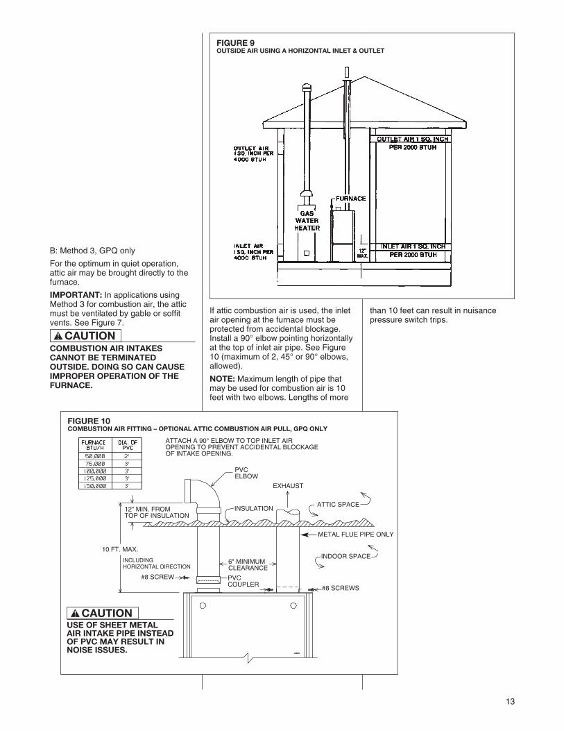
FIGURE 9OUTSIDE AIR USING A HORIZONTAL INLET & OUTLET
FIGURE 10COMBUSTION AIR FITTING – OPTIONAL ATTIC COMBUSTION AIR PULL, GPQ ONLY
B: Method 3, GPQ only
For the optimum in quiet operation,attic air may be brought directly to thefurnace.
IMPORTANT: In applications usingMethod 3 for combustion air, the atticmust be ventilated by gable or soffitvents. See Figure 7.
COMBUSTION AIR INTAKESCANNOT BE TERMINATEDOUTSIDE. DOING SO CAN CAUSEIMPROPER OPERATION OF THEFURNACE.
If attic combustion air is used, the inletair opening at the furnace must beprotected from accidental blockage.Install a 90° elbow pointing horizontallyat the top of inlet air pipe. See Figure10 (maximum of 2, 45° or 90° elbows,allowed).
NOTE: Maximum length of pipe thatmay be used for combustion air is 10feet with two elbows. Lengths of more
INCLUDINGHORIZONTAL DIRECTION
ATTACH A 90° ELBOW TO TOP INLET AIROPENING TO PREVENT ACCIDENTAL BLOCKAGEOF INTAKE OPENING.
than 10 feet can result in nuisancepressure switch trips.
CAUTION!
PVCELBOW
#8 SCREWS
#8 SCREW
METAL FLUE PIPE ONLY
10 FT. MAX.
12" MIN. FROMTOP OF INSULATION
6" MINIMUMCLEARANCE
PVCCOUPLER
EXHAUST
ATTIC SPACE
INDOOR SPACE
INSULATION
CAUTION!
USE OF SHEET METALAIR INTAKE PIPE INSTEADOF PVC MAY RESULT INNOISE ISSUES.

14
GENERAL INFORMATIONThe furnace must be vented inaccordance with these instructions,National Fuel Gas Code, ANSI Z223.1and/or the Natural Gas InstallationCode, CSA-B149.1 & .2 andrequirements or codes of the local utilityor other authority having jurisdiction.
DEVICES ATTACHED TO THE FLUEOR VENT FOR THE PURPOSE OFREDUCING HEAT LOSS UP THECHIMNEY HAVE NOT BEEN TESTEDAND HAVE NOT BEEN INCLUDEDIN THE DESIGN CERTIFICATION OFTHIS FURNACE. WE, THEMANUFACTURER, CANNOT ANDWILL NOT BE RESPONSIBLE FORINJURY OR DAMAGE CAUSED BYTHE USE OF SUCH UNTESTEDAND/OR UNCERTIFIED DEVICES,ACCESSORIES OR COMPONENTS.
DRAFT INDUCER
VENT PIPE ATTACHING HOLESMUST BE PREDRILLED IN THEDRAFT INDUCER COLLAR TOPREVENT DAMAGING THEINDUCER. DRILL 1/8” DIAMETERHOLES THROUGH THE VENT PIPEAND COLLAR AND USE #8 SCREWSTO ATTACH. SEE FIGURE 11.FAILURE TO FOLLOW THISWARNING CAN CAUSERECIRCULATION OF FLUEPRODUCTS CAUSING CARBONMONOXIDE POISONINGRESULTING IN PERSONAL INJURYOR DEATH.
IMPORTANT APPLICATIONNOTESWhen the furnace is used as areplacement, the existing vent systemshould be inspected to assure thatthere are no obstructions, blockage, orany signs of corrosion and is properlysized for use with this furnace.
NOTE: When the vent table permitsmore than one diameter of pipe for aconnector or vent, the smallestpermitted diameter must be used.
Vent pipe may be type “B-1,” eitherrigid or suitable flexible constructionthat carries a u.l. listing.
Common venting is allowed withvertical B-1 vent systems, and linedmasonry chimneys. Follow the NationalFuel Gas Code, ANSI Z223.1 and/orthe Natural Gas Installation Code,CSA-B149.1 & .2 for proper installationpractices.
NOTE: Follow combustion airinstructions as outlined in this manual.
Single wall vent connectors to “B-1vent or masonry chimneys” may beused under the guidelines of theNational Fuel Gas Code, ANSI Z223.1and/or the Natural Gas InstallationCode, CSA-B149.1 & .2.
The entire length of the ventconnector shall be readilyaccessible for inspection, cleaningand replacement.
WARNING!
WARNING!
FURNACE CATEGORYINFORMATIONThis furnace is shipped as a Category Itype induced draft furnace. A CategoryI furnace operates with a nonpositivevent pressure and has a vent gastemperature at least 140°F above thedew point of the vent gases. ACategory I type may be a draft hoodequipped furnace or have a fanassisted combustion system (induceddraft). The inducer is used to pull flueproducts through the combustionchamber and as they leave thefurnace, most of the energy has beendissipated. The buoyant effect of theflue gases provides venting to theoutdoors.
During the off cycle, the inducer is offand there is very little flow through thevent, cooling the vent. During the oncycle there is no dilution airflow, aswith a draft hood type furnace.Although the vent heats up rapidlywithout dilution air, the flue productscontain more water vapor, whichresults in a higher dew pointtemperature. It is most important thatyou follow the guidelines in theseinstructions to prevent the possibleformation of condensation in theventing system.
As a Category I furnace it may bevented vertically with type B-1 ventpipe and also may be common vented,as described in these instructions.
FIGURE 11ATTACHING TO DRAFT INDUCER COLLAR
VENTING
A0991-01

15
“B-1” VERTICAL VENTINGType “B-1” vents must be installed inaccordance with the terms of theirlistings and the vent manufacturer’sinstructions.
“B-1” vents must be supported andspaced in accordance with their listingsand the manufacturer’s instructions. Allvents must be supported to maintaintheir minimum clearances fromcombustible material.
VERTICAL VENTING
CategorizedFurnace Vent
Input Size Required50K 3”75K *4”
100K *4”125K *5”150K *5”
*NOTE: All furnaces have a 3” ventconnection as shipped from the factory. A 3”to 4” or 3” to 5” vent transition is required onall but the 50,000 BTUH models whenvertically vented or common vented withmetal vent pipes. THE VENT TRANSITIONCONNECTION MUST BE MADE AT THEFURNACE VENT EXIT. It must originatewith an adapter if required, at the furnaceflue collar and terminate either in a listedcap or roof assembly. When commonventing, the vent connector size may differfrom the above diameters depending onapplication. See ANSI Z21.47-1993/CSA-2.3-M93 or latest edition tables.
VERTICAL VENT SYSTEMS:1. A gas vent shall terminate above the
roof surface with a listed cap orlisted roof assembly. Gas vents 12inches in size or smaller with listedcaps shall be permitted to beterminated in accordance withFigure 12, provided they are at least8 feet from a vertical wall or similarobstruction. All other gas vents shallterminate not less than 2 feet abovethe highest point where they passthrough the roof and at least 2 feethigher than any portion of a buildingwithin 10 feet.
2. A type B-1 gas vent shall terminateat least 5 feet in vertical heightabove the highest connectedequipment draft hood or flue collar.
3. Must rise 1/4” per foot away from thefurnace on horizontal runs and besupported with straps or hangers soit has no sags or dips. Supports at 4foot intervals and at all elbows arerecommended.
4. The vent connector must bemechanically fastened to the outletcollar of the furnace with at least (2)sheet metal screws except ventconnectors that are B-1 material.
DO NOT CONNECT THIS FURNACETO A CHIMNEY USED TO VENT ASOLID FUEL APPLIANCE (WOODOR COAL). VENTING WITH A SOLIDFUEL APPLIANCE CAN LEAD TOIMPROPER FUNCTIONING OF THEUNIT, AND DUE TO SOOTING, THEPOSSIBILITY OF FIRE RESULTINGIN PROPERTY DAMAGE,PERSONAL INJURY OR DEATH.
SPECIAL VENT SYSTEMS (SVS)IMPORTANT: It is THE FURNACEMANUFACTURER’s position now thatnew installations of any HTPV pipeused in a category III vent application,including Selkirk’s Selvent™ II HTPVproduct, should cease immediately.
These shall be assembled inaccordance with the manufacturer’sinstructions. See Figure 11.
5. Any angle greater than 45 degreesfrom the vertical is consideredhorizontal. The total horizontaldistance of a vent plus the horizontalvent connector serving draft-hoodequipped appliances shall not begreater than 75 percent of thevertical height of the vent.
NOTE: Refer to the National Fuel GasCode, ANSI Z223.1 and/or the NaturalGas Installation Code, CSA-B149.1 & .2.
Single appliance venting of a fanassisted furnace into a tile-linedmasonry chimney is prohibited. Thechimney must be lined with either TypeB vent or with a listed, single wall,metal lining system. ReferenceNational Fuel Gas Code, ANSI Z223.1and/or the Natural Gas InstallationCode, CSA-B149.1 & .2. See Figure 13for typical B-1 vent chase.
FIGURE 12TYPICAL VENTING WITH “B-1” VENT
WARNING!

16
EXISTING VENT SYSTEMSIMPORTANT RETROFITVENTING INSTRUCTIONSIf this furnace is a replacementinstallation, ALWAYS INSPECT theexisting vent system to be sure thereare no obstructions, blockages, orsigns of corrosion.
When the existing furnace is removedfrom a venting system serving otherappliances, the venting is likely to betoo large to properly vent the remainingattached appliances.
The following steps shall be followedwith each appliance that remainsconnected to the common ventingsystem, while the other appliances thatremain connected to the commonventing systems are not in operation.
NOTE: When the vent table permitsmore than one diameter of pipe for aconnector or vent, the smallestpermitted diameter must be used.1.Seal any unused openings in thecommon venting system.
1. Visually inspect the venting systemfor proper size and horizontal pitchand determine that there is noblockage, restriction, leakage,corrosion or other deficiencies whichcould cause an unsafe condition.
2. Insofar as is practical, close allbuilding doors, windows and alldoors between the space where theappliances remaining connected to
FIGURE 13DEDICATED VENTING THROUGHCHIMNEY WITH “B-1” VENT
the common venting system arelocated. Turn on clothes dryers andany appliance not connected to thecommon venting system. Turn onany exhaust fans, such as rangehoods and bathroom exhausts, sothey will operate at maximum speed.Do not operate a summer exhaustfan. Close fireplace dampers.
3. Follow the lighting instructions.Place the appliance being inspectedinto operation. Adjust the thermostatso the appliance will operatecontinuously.
4. Test for spillage at the draft hoodrelief opening after 5 minutes ofmain burner operation. Use theflame of a match or candle, orsmoke from a cigarette, cigar, orpipe.
5. After it has been determined thateach appliance that remainsconnected to the common ventingsystem properly vents (when testedas outlined above) return doors,windows, exhaust fans, fireplacedampers and any other gas-burningappliance to their previousconditions of use.
6. If improper venting is observedduring any of the above tests, thecommon venting system must beresized. Refer to National Fuel GasCode, ANSI Z223.1 and/or theNatural Gas Installation Code, CSA-B149.1 & .2.
POWER VENT SYSTEMSWhen vertical venting is not possible,the only acceptable method forhorizontal venting is with the use ofTjernlund model GPAK-1TR or FieldControls models SWG-4R powerventer. Type B vent pipe and fittingsmust be used. Common venting is notpermitted
All application and installationinstructions supplied with the powerventer must be followed.
Please address all questions regardingpower venter installation, agencylistings and furnace model compatibilityto:
Tjernlund Products, Inc.(800) 255-4208 or (612) 426-2993
Field Controls L.L.C.(800) 742-8368 or (919) 522-0214
CHIMNEY-FRIENDLYADAPTER SYSTEMThis furnace can be used with chimneyadapter RXGW-B01.

17
FIGURE 14GAS PIPING INSTALLATION
GAS PIPE INSTALLATION
GAS SUPPLY AND PIPINGGAS SUPPLY
THIS FURNACE IS EQUIPPED ATTHE FACTORY FOR USE ONNATURAL GAS ONLY. CONVERSIONTO LP GAS REQUIRES A SPECIALKIT AVAILABLE FROM THEDISTRIBUTOR. FAILURE TO USETHE PROPER CONVERSION KIT CANCAUSE FIRE, CARBON MONOXIDEPOISONING, EXPLOSION,PROPERTY DAMAGE, PERSONALINJURY OR DEATH.
See the conversion kit index suppliedwith the furnace. This index identifiesthe proper LP Gas Conversion Kitrequired for each particular furnace.
IMPORTANT: Any additions, changesor conversions required for the furnaceto satisfactorily meet the applicationshould be made by a qualified installer,service agency or the gas supplier,using factory-specified or approvedparts. In the commonwealth ofMassachusetts, installation must beperformed by a licensed plumber or gasfitter for appropriate fuel.
IMPORTANT: Connect this furnaceonly to gas supplied by a commercialutility.
IMPORTANT: A U.L. recognizedfuel gas and CO detector(s) arerecommended in all applications,and their installation should be inaccordance with the detectormanufacturer’s recommendationsand/or local laws, rules, regulations orcustoms.
GAS PIPING (SEE FIGURE 14)Install the gas piping according to alllocal codes, state codes and regulationsof the utility company, whichever holdsjurisdiction.
If possible, run a separate gas supplyline directly from the meter to thefurnace. Consult the local gas companyfor the location of the manual main shut-off valve. The gas line and manual gasvalve must be adequate in size toprevent undue pressure drop andnever smaller than the pipe size tothe combination gas valve on thefurnace. Refer to Table 2 for the recom-mended pipe size for natural gas andTable 3 for LP gas pipe sizes.
IMPORTANT: It is permissible to runflexible gas connector inside the unit to
! WARNING
a piece of black pipe. If local codesallow the use of a flexible gas applianceconnector, always use a new listedconnector. Do not use a connectorwhich has previously serviced anothergas appliance. Massachusetts lawlimits flexible gas connectors to amaximum of 36”.
Install a ground joint union outsidethe cabinet to easily remove thecontrol valve assembly. Install amanual shut-off valve in the gas lineoutside the furnace casing. The valveshould be readily accessible to turn thegas supply on or off. Install a drip leg inthe gas supply line as close to thefurnace as possible. Always use a pipecompound resistant to the action ofliquefied petroleum gases on allthreaded connections.
IMPORTANT: When making gas pipeconnections, use a back-up wrench toprevent any twisting of the controlassembly and gas valve. Do notovertighten the connection.
Any strains on the gas valve canchange the position of the gas orificesin the burners. This can cause erraticfurnace operation.
IMPORTANT: ENSURE that thefurnace gas control valve not besubjected to high gas line supplypressures.
DISCONNECT the furnace and itsindividual shut-off valve from the gassupply piping during any pressuretesting that exceeds 1/2 PSIG (3.48 kPa).
GROMMET(IN NORMAL POSITION)
GAS VALVE
MANIFOLD
MANIFOLD
FLAME SENSOR
FLAMESENSOR
BURNERS
BURNERS
DIRECT SPARKIGNITOR
DIRECT SPARK IGNITOR
MANUAL GAS VALVE (IN CLOSED POSITION)
UNION
DUCTUNION
DRIP LEG
DRIP LEG
4 TO 5 FEETABOVE FLOOR
REQ'D BY SOMEUTILITIES
4 TO 5 FEETABOVE FLOOR
REQ'D BY SOMEUTILITIES
GROMMET(IN NORMALPOSITION)
UPFLOW & DOWNFLOW
HORIZONTAL
MANUAL GAS VALVE(IN CLOSED POSITION)
GAS VALVE
LP CONVERSIONNOTE: For installation, see specific LPkit installation instructions.
The valve can be converted to useliquefied petroleum (LP) gas byreplacing the pressure regulator springwith the conversion kit spring. This LPkit spring allows the regulator tomaintain the proper adjusted manifoldpressure for LP gas. The correct burnerLP orifices are included in the kit.
NOTE: Order the correct LP conversionkit from the local distributor. Furnaceconversion to LP gas must beperformed by a qualified technician.
ELEVATIONS ABOVE 2000 FTREQUIRE THAT THE FURNACEINPUT RATING BE ADJUSTED ANDTHAT THE SIZE OF THE BURNERORIFICES BE RE-CALCULATEDBASED ON ELEVATION AND GASHEATING VALUE. THE BURNERORIFICES MAY (OR MAY NOT) NEEDTO BE CHANGED. SEE THESECTION TITLED “HIGH ALTITUDEINSTALLATIONS” OF THIS BOOKFOR INSTRUCTIONS.
18
GAS PRESSUREIMPORTANT: The maximum gassupply pressure to the furnace shouldbe 10.5” w.c. for natural gas and 13”w.c. for LP gas.
Natural gas supply pressure shouldoperate between 5" to 10.5” w.c. LPgas supply pressure should be 11” to13” w.c. This pressure must bemaintained with all other gas-firedappliances in operation.
NOTE: Do not exceed a gas pressureof 13” w.c.
ELEVATIONS ABOVE 2000 FTREQUIRE THAT THE FURNACEINPUT RATING BE ADJUSTED ANDTHAT THE SIZE OF THE BURNERORIFICES BE RE-CALCULATEDBASED ON ELEVATION AND GASHEATING VALUE. THE BURNERORIFICES MAY (OR MAY NOT) NEEDTO BE CHANGED. SEE THESECTION TITLED “HIGH ALTITUDEINSTALLATIONS” OF THIS BOOKFOR INSTRUCTIONS.
NEVER PURGE A GAS LINE INTOTHE COMBUSTION CHAMBER.NEVER USE MATCHES, FLAME ORANY IGNITION SOURCE FORCHECKING LEAKAGE. FAILURE TOFOLLOW THIS WARNING CANCAUSE AN EXPLOSION OR FIRERESULTING IN PROPERTYDAMAGE, PERSONAL INJURY ORDEATH.
To check for gas leakage, use anapproved chloride-free soap and watersolution, an electronic combustible gasdetector, or other approved method.
! WARNING
! CAUTION
! CAUTION
NOx MODELSWhen converting furnaces equippedwith NOx inserts to LP gas, remove theNOx insert assemblies. Steps forremoval are listed below:
1. Turn off all electrical power and thegas supply to the furnace.
2. Remove the burner door from thefurnace.
3. Remove the igniter assembly –handle with care.
4. Remove the two screws attachingthe NOx insert retainer brackets tothe center panel. Pull the retainerrod.
5. Put the two screws back into theholes in the center panel.
6. Re-install the igniter and burnerassemblies.
7. Replace burner door.
8. Turn on electrical power and gassupply to the unit.
NOTE: Some NOx models may haveone less NOx insert.
19
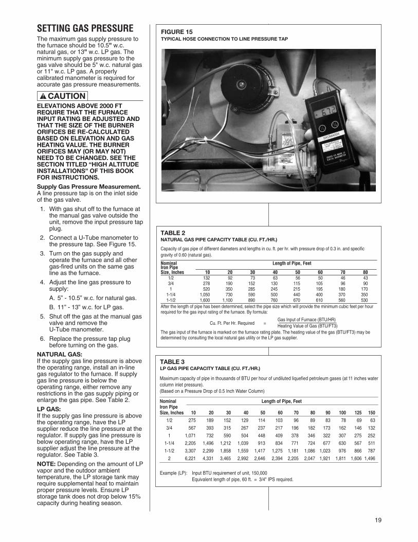
TABLE 3LP GAS PIPE CAPACITY TABLE (CU. FT./HR.)
SETTING GAS PRESSUREThe maximum gas supply pressure tothe furnace should be 10.5” w.c.natural gas, or 13” w.c. LP gas. Theminimum supply gas pressure to thegas valve should be 5" w.c. natural gasor 11" w.c. LP gas. A properlycalibrated manometer is required foraccurate gas pressure measurements.
ELEVATIONS ABOVE 2000 FTREQUIRE THAT THE FURNACEINPUT RATING BE ADJUSTED ANDTHAT THE SIZE OF THE BURNERORIFICES BE RE-CALCULATEDBASED ON ELEVATION AND GASHEATING VALUE. THE BURNERORIFICES MAY (OR MAY NOT)NEED TO BE CHANGED. SEE THESECTION TITLED “HIGH ALTITUDEINSTALLATIONS” OF THIS BOOKFOR INSTRUCTIONS.
Supply Gas Pressure Measurement.A line pressure tap is on the inlet sideof the gas valve.
1. With gas shut off to the furnace atthe manual gas valve outside theunit, remove the input pressure tapplug.
2. Connect a U-Tube manometer tothe pressure tap. See Figure 15.
3. Turn on the gas supply andoperate the furnace and all othergas-fired units on the same gasline as the furnace.
4. Adjust the line gas pressure tosupply:
A. 5” - 10.5” w.c. for natural gas.
B. 11” - 13” w.c. for LP gas.
5. Shut off the gas at the manual gasvalve and remove theU-Tube manometer.
6. Replace the pressure tap plugbefore turning on the gas.
NATURAL GAS:If the supply gas line pressure is abovethe operating range, install an in-linegas regulator to the furnace. If supplygas line pressure is below theoperating range, either remove anyrestrictions in the gas supply piping orenlarge the gas pipe. See Table 2.
LP GAS:If the supply gas line pressure is abovethe operating range, have the LPsupplier reduce the line pressure at theregulator. If supply gas line pressure isbelow operating range, have the LPsupplier adjust the line pressure at theregulator. See Table 3.
NOTE: Depending on the amount of LPvapor and the outdoor ambienttemperature, the LP storage tank mayrequire supplemental heat to maintainproper pressure levels. Ensure LPstorage tank does not drop below 15%capacity during heating season.
FIGURE 15TYPICAL HOSE CONNECTION TO LINE PRESSURE TAP
Maximum capacity of pipe in thousands of BTU per hour of undiluted liquefied petroleum gases (at 11 inches watercolumn inlet pressure).(Based on a Pressure Drop of 0.5 Inch Water Column)
Nominal Length of Pipe, FeetIron PipeSize, Inches 10 20 30 40 50 60 70 80 90 100 125 150
1/2 275 189 152 129 114 103 96 89 83 78 69 63
3/4 567 393 315 267 237 217 196 182 173 162 146 132
1 1,071 732 590 504 448 409 378 346 322 307 275 252
1-1/4 2,205 1,496 1,212 1,039 913 834 771 724 677 630 567 511
1-1/2 3,307 2,299 1,858 1,559 1,417 1,275 1,181 1,086 1,023 976 866 787
2 6,221 4,331 3,465 2,992 2,646 2,394 2,205 2,047 1,921 1,811 1,606 1,496
Example (LP): Input BTU requirement of unit, 150,000Equivalent length of pipe, 60 ft. = 3/4" IPS required.
TABLE 2NATURAL GAS PIPE CAPACITY TABLE (CU. FT./HR.)
Capacity of gas pipe of different diameters and lengths in cu. ft. per hr. with pressure drop of 0.3 in. and specificgravity of 0.60 (natural gas).
Nominal Length of Pipe, FeetIron PipeSize, Inches 10 20 30 40 50 60 70 80
1/2 132 92 73 63 56 50 46 433/4 278 190 152 130 115 105 96 901 520 350 285 245 215 195 180 170
1-1/4 1,050 730 590 500 440 400 370 3501-1/2 1,600 1,100 890 760 670 610 560 530
After the length of pipe has been determined, select the pipe size which will provide the minimum cubic feet per hourrequired for the gas input rating of the furnace. By formula:
Gas Input of Furnace (BTU/HR)Cu. Ft. Per Hr. Required = Heating Value of Gas (BTU/FT3)
The gas input of the furnace is marked on the furnace rating plate. The heating value of the gas (BTU/FT3) may bedetermined by consulting the local natural gas utility or the LP gas supplier.
! CAUTION

20
TABLE 4
ADJUSTING OR CHECKINGFURNACE INPUT
ELEVATIONS ABOVE 2000 FTREQUIRE THAT THE FURNACEINPUT RATE BE ADJUSTED ANDTHAT THE SIZE OF THE BURNERORIFICES BE RE-CALCULATEDBASED ON ELEVATION AND GASHEATING VALUE. THE BURNERORIFICES MAY (OR MAY NOT) NEEDTO BE CHANGED. SEE THE SECTIONTITLED “HIGH ALTITUDEINSTALLATIONS” OF THIS BOOKFOR INSTRUCTIONS.
NATURAL GAS:The maximum gas supply pressure tothe furnace should be 10.5” W.C. fornatural gas. The minimum gas supplypressure for purposes of inputadjustment to the furnace should be 5”W.C.
A properly calibrated manometer orgauge is required for accurate gaspressure readings.
The manifold pressure should be set at3.5” W.C. for natural gas. Only smallvariations in the gas flow should bemade by means of the pressureregulator adjustment.
To adjust the pressure regulator:
1. Remove the regulator cap.
2. Turn the adjustment screw clockwiseto increase pressure orcounterclockwise to decreasepressure.
3. Replace the regulator cap securely.
LP GAS:Furnaces for use on LP gas, the LP gassupply pressure must be set between11.0” and 13.0” W.C. by means of thetank or branch supply regulators. Thefurnace manifold pressure should be setat 10” W.C. at the gas control valve. Forelevations up to 8,000 feet, rating plateinput ratings apply. For high altitudes(elevations 8,000 and over) and for anynecessary major changes in the gasflow rate the orifice spud must bechanged.
TO CHANGE ORIFICE SPUDS:
1. Shut off the manual main gas valveand remove the gas manifold.
2. Replace the orifice spuds.
3. Reassemble in reverse order.
4. Turn the gas supply back on andcheck for leaks.
5. Check for proper operation andmanifold pressure.
Check of input is important to preventover firing of the furnace beyond itsdesign-rated input. NEVER SET INPUTABOVE THAT SHOWN ON THERATING PLATE.
TO CHECK FURNACE INPUT:
1. Make certain that all other gasappliances are shut off, with theexception of pilot burners.
2. Start the furnace
3. Time the meter to measure the timerequired to burn one cubic foot ofgas.
4. Use Table 4 to determine input rate.
METER TIME IN MINUTES AND SECONDS FOR NORMALINPUT RATING OF FURNACES EQUIPPED FOR NATURAL OR LP GAS
INPUTBTU/HR
METERSIZE
CU. FT.
HEATING VALUE OF GAS BTU PER CU. FT.900 1000 1040 1100 2500
MIN. SEC. MIN. SEC. MIN. SEC. MIN. SEC. MIN. SEC.ONE 1 5 1 12 1 15 1 18 3 2050,000 TEN 10 50 12 00 12 30 13 12 30 00
ONE 0 44 0 48 0 50 0 53 2 075,000 TEN 7 12 8 0 8 19 8 48 20 0
ONE 0 33 0 36 0 38 0 40 1 30100,000 TEN 5 24 6 0 6 15 6 36 15 0
ONE 0 26 0 29 0 30 0 32 1 12125,000 TEN 4 19 4 48 5 0 5 17 12 0
ONE 0 31 0 24 0 25 0 26 1 0150,000 TEN 3 36 4 0 4 10 4 20 10 0
Heating Value of Gas (BTU/Ft3) x 3600 x correction factorInput BTU/HR =
Time in Seconds (for 1 cu.ft.) of Gas
! CAUTION

FIGURE 16ISOLATION RELAY
21
TURN OFF ELECTRIC POWER ATTHE FUSE BOX OR SERVICE PANELBEFORE MAKING ANYELECTRICAL CONNECTIONS.
ALSO, THE GROUND CONNECTIONMUST BE COMPLETED BEFOREMAKING LINE VOLTAGECONNECTIONS. FAILURE TO DOSO CAN RESULT IN ELECTRICALSHOCK, SEVERE PERSONALINJURY OR DEATH.
IMPORTANT: The furnace must beinstalled so that the electricalcomponents are protected from waterdue to improper flue installation orevaporator condensate drain run-off,etc.
ELECTRICAL CONNECTIONS
THE CABINET MUST BEPERMANENTLY GROUNDED. AGROUND SCREW IS PROVIDED INTHE JUNCTION BOX FOR THISPURPOSE. FAILURE TO DO SO CANRESULT IN FIRE, ELECTRICALSHOCK, PERSONAL INJURY ORDEATH.
The electrical supply requirements arelisted on the furnace rating plate.
Use a separate fused branch electricalcircuit containing a properly sized fuseor circuit breaker. Run this circuitdirectly from the main switch box to anelectrical disconnect which must bereadily accessible and located withinsight of the furnace. Connect from thedisconnect to the junction box on theleft side of the furnace, inside thecontrol compartment. See appropriatewiring diagram.
NOTE: The electrical junction boxinside the furnace control compartmentmay be relocated to the right side ifnecessary. A knockout is provided.
NOTE: L1 (hot) and neutral polaritymust be observed when making fieldconnections to the furnace. Theignition control on electric ignitionmodels will not sense flame if L1 andneutral are reversed.
Installation of the electric supply lineshould be in accordance with theNational Electric Code ANSI/NFPA No.70, latest edition, or CanadianElectrical Code Part 1 - CSA StandardC22.1 and local building codes.
This can be obtained from:
National Fire Protection AssociationBatterymarch ParkQuincy, MA 02269
Canadian Standards Association178 Rexdale Blvd.Etobicoke (Toronto), OntarioCanada M9W, 1R3
WARNING!
WARNING!
ELECTRICAL WIRING
drafts, concealed hot or cold waterpipes, lighting fixtures, radiation fromfireplace, rays of sun, lamps, television,radios or air streams from registers.Refer to the instructions packed withthe thermostat for best anticipatoradjustment or selection or see below.
HEAT ANTICIPATOR SETTINGS
For adjusting the thermostat heatanticipator setting; (a) add the currentdraw of the various components in thesystem or (b) using jumper wire,measure the current flow between theR and W thermostat circuits. Set thethermostat heat anticipator accordingto the current flow measured.
The room thermostat must becompatible with the integrated furnacecontrol on the furnace. Generally, allthermostats that are not of the “currentrobbing” type are compatible with theintegrated furnace control used.
NOTE: An isolation relay (part number42-25104-01) may assist with “currentrobbing” type thermostat compatibilityproblems. Use a single-pole, single-throw relay with a 24-volt AC coil. Thecontacts should be rated for .5 ampsminimum at 24 volts. See Figure 16.
Install the room thermostat inaccordance with the instruction sheetin the box with the thermostat. Run thethermostat lead wires inside the controlcompartment. Connect the thermostatas shown on the wiring diagram. Neverinstall the thermostat on an outsidewall or where it will be influenced by
THERMOSTAT
ST-A0804-01
TABLE 5FIELD WIRE SIZE FOR 24 VOLT CONTROL CIRCUITS
SOLID COPPER WIRE - AWG
3.0 16 14 12
2.5 16 14 12
2.0 18 16 14
50 100 150
LENGTH OF RUN - FEET ➀
➀ Wire length equals twice the run distance
NOTE: Do not use 24 volt control wiring smaller than No. 18.
THER
MOS
TAT
LOAD
- AM
PS
TWIN
Y GR
W2
W1
C
22
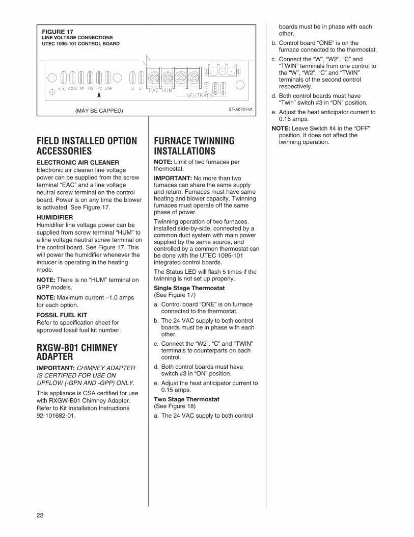
FIELD INSTALLED OPTIONACCESSORIESELECTRONIC AIR CLEANERElectronic air cleaner line voltagepower can be supplied from the screwterminal “EAC” and a line voltageneutral screw terminal on the controlboard. Power is on any time the bloweris activated. See Figure 17.
HUMIDIFIERHumidifier line voltage power can besupplied from screw terminal “HUM” toa line voltage neutral screw terminal onthe control board. See Figure 17. Thiswill power the humidifier whenever theinducer is operating in the heatingmode.
NOTE: There is no “HUM” terminal onGPP models.
NOTE: Maximum current –1.0 ampsfor each option.
FOSSIL FUEL KITRefer to specification sheet forapproved fossil fuel kit number.
RXGW-B01 CHIMNEYADAPTERIMPORTANT: CHIMNEY ADAPTERIS CERTIFIED FOR USE ONUPFLOW (-GPN AND -GPP) ONLY.
This appliance is CSA certified for usewith RXGW-B01 Chimney Adapter.Refer to Kit Installation Instructions 92-101682-01.
FURNACE TWINNINGINSTALLATIONSNOTE: Limit of two furnaces perthermostat.
IMPORTANT: No more than twofurnaces can share the same supplyand return. Furnaces must have sameheating and blower capacity. Twinningfurnaces must operate off the samephase of power.
Twinning operation of two furnaces,installed side-by-side, connected by acommon duct system with main powersupplied by the same source, andcontrolled by a common thermostat canbe done with the UTEC 1095-101integrated control boards.
The Status LED will flash 5 times if thetwinning is not set up properly.
Single Stage Thermostat(See Figure 17)
a. Control board “ONE” is on furnaceconnected to the thermostat.
b. The 24 VAC supply to both controlboards must be in phase with eachother.
c. Connect the “W2”, “C” and “TWIN”terminals to counterparts on eachcontrol.
d. Both control boards must haveswitch #3 in “ON” position.
e. Adjust the heat anticipator current to0.15 amps.
Two Stage Thermostat(See Figure 18)
a. The 24 VAC supply to both control
boards must be in phase with eachother.
b. Control board “ONE” is on thefurnace connected to the thermostat.
c. Connect the “W”, “W2”, “C” and“TWIN” terminals from one control tothe “W”, “W2”, “C” and “TWIN”terminals of the second controlrespectively.
d. Both control boards must have“Twin” switch #3 in “ON” position.
e. Adjust the heat anticipator current to0.15 amps.
NOTE: Leave Switch #4 in the “OFF”position. It does not affect thetwinning operation.
FIGURE 17LINE VOLTAGE CONNECTIONSUTEC 1095-101 CONTROL BOARD
ST-A0761-01(MAY BE CAPPED)

23
FIGURE 18UT ELECTRONIC CONTROLS NO. 1095-100 CONTROL BOARDTWINNING CONNECTION SINGLE STAGE OPERATION
I685

24
FIGURE 19UT ELECTRONIC CONTROLS NO. 1095-100 CONTROL BOARDTWINNING CONNECTION TWO STAGE OPERATION
I684

25
80+ HIGH ALTITUDEINSTRUCTIONS(TABLES 6 & 9)
THE NATIONAL FUEL GAS CODE(NFGC) GUIDELINES SHOULD BEFOLLOWED WHEN CONVERTINGTHESE FURNACES FOR HIGHALTITUDE OPERATION.
34" 80 Plus furnaces installed above2,000 ft. require the furnace to be de-rated 4% per thousand feet.
IMPORTANT: Factory installed orificesare calculated and sized based on a sealevel Natural Gas heating value of 1075BTU per cubic ft. NOTE: Orifices are available throughyour local distributor.
Reference Tables 6 and 9 forappropriate orifice sizing.
The following are examples of orificesizing using the National Fuel Gas CodeAppendix F:
For a simplified estimation of orifice sizebased on gas heating value andelevation, Tables 6 and 9 may be used.However, calculations are the bestmethod.
Example: 900 BTU/ft3 RegionalNatural Gas Heating Value
I/H = Q25000 / 900 = 27.78 ft3
I = Sea Level input (per burner): 25000H = Sea Level Heating Value: 900Q = 27.78 ft3 Natural Gas per hour.
From Table F.1 of National Fuel GasCode Handbook, 2002 (3.5� w.c.column).
Orifice required at Sea Level: #40
From Table F.4 of National Fuel GasCode Handbook, 2002Orifice required at 5000 ft. elevation (4%de-rate per thousand ft): #42
Orifice required at 8000 ft. elevation (4%de-rate per thousand ft.): #44
Example: 1050 BTU/ft3 RegionalNatural Gas Heating Value
I / H = Q25000 / 1050 = 23.81ft3
I = Sea Level input (per burner): 25000H = Sea Level Heating Value: 1050Q = 23.81 ft3 Natural Gas per hour.
From Table F.1 of Natural Fuel GasCode Handbook, 2002 (3.5� w.c.column).
Orifice required at Sea Level: #43
From Table F.4 of National Fuel GasCode Handbook, 2002
Orifice required at 5000 ft. elevation(4% de-rate per thousand ft.): #45
Orifice required at 8000 ft elevation (4%de-rate per thousand ft): #47
LP GAS (TABLE 7)NOTE: Keep any parts removed duringLP conversion procedure stored withthe product literature for future use.
LP Gas is a manufactured gas that hasconsistent heating value across mostregions.
The NFGC guidelines are used with thefollowing exception:
The recommended LP Gas highaltitude orifice selections differ slightlyin that the NFGC LP orifice chart, asthey are not accurate for Rheemproducts. The National Fuel Gas CodeLP orifices are based on an 11" ofwater column pressure at the orifice,which differs from products that use 10"of water column at the orifice. Thisdifference requires a deviation from theNFGC orifice size recommendations.The Sea Level input should still bereduced by 4% per thousand ft. and theorifice size must be selected based onthe reduced input in Table 7.
FIGURE 20MANIFOLD PRESSURE-CHANGE LABEL
THE MANIFOLD PRESSURE OF THIS APPLIANCE HAS BEEN FIELD ADJUSTED TO OBTAIN THE CORRECT INPUT RATING FOR INSTALLATION AT ALTITUDES
BETWEEN 2,000 FEET AND 4,500 FEET ELEVATION.
LA PRESSION DU DISTRIBUTEUR D'ALIMENTATION DE CET APPAREIL A ÉTÉ AJUSTÉ SUR LES LIEUX AFIN D'OBTENIR LA BONNE PUISSANCE D'ENTRÉE POUR
UNE INSTALLATION ENTRE 2000 ET 4500 PIEDS D'ALTITUDE.
92-24399-01-01
! CAUTION
Natural Gas Orifice Drill Size (4% per 1000 ft. De-Rate)IMPORTANT: 80+ Models only. Do not use this chart for any 90+ Models.
Burner Input (per burner) 25,000 BTU @ Sea Level
Sea level 2000 to 3000 to 4000 to 5000 to 6000 to 7000 to 8000 toto 1999 ft 2999 ft 3999 ft 4999 ft 5999 ft 5999 ft 7999 ft 8999 ft
38 39 40 41 41 42 42 4340 41 42 42 42 43 43 4441 42 42 42 43 43 44 4442 42 43 43 43 44 44 4543 44 44 44 45 45 46 47
Annual Avg. HeatValue (btu per ft3)
850900975
10751170
TABLE 6
TABLE 7LP GASIMPORTANT: 80+ MODELS ONLY! DO NOTUSE THIS CHART WITH ANY 90+ MODELS.
Input (per OrificeAltitude burner) 25000 Size
0 to 2000 ft. 25000 #542000�-3000� 24000 #543000�-4000� 23000 #544000�-5000� 22000 #545000�-6000� 21000 #546000�-7000� 20000 #547000�-8000� 19000 #558000�-9000� 18000 #559000�-10000� 17000 #55

26
ORIFICE ORDERINGINFORMATIONOrifice sizes are selected by adding the2-digit drill size required in the orificepart number. Drill sizes available are 39through 64; metric sizes available1.10mm (-90) and 1.15mm (-91):
Orifice Part Number 62-22175-(drill size)
Example 1:# 60 drill size orifice requiredPart # 62-22175-60
Example 2:1.15mm drill size orifice requiredPart # 62-22175-91
ALTERNATE METHOD FORCANADIAN HIGH-ALTITUDEDERATEIn Canada, unless an orifice change isspecifically mandated by local codes,an alternate method of altitude derationthrough a reduction in manifoldpressure is acceptable as described inTable 8. This information is based on aheating value of 1000 BTU per cubicfeet of natural gas, and 2500 BTU percubic feet of LP gas. IMPORTANT: Actual input rates mustbe measured onsite with manifoldpressure adjustment to ensure that anactual 10% reduction in input rate isachieved.Once this field adjustment has beenmade, the label shown in Figure 20must be affixed in a conspicuouslocation on the front of the furnacecabinet.NOTE: This label is supplied in theinformation packet shipped with eachfurnace.
TABLE 8ALTERNATE METHOD FOR CANADIAN HIGH-ALTITUDE DERATEIMPORTANT: 80+ MODELS ONLY! DO NOT USE THIS CHART WITH ANY 90+ MODELS.
NATURAL GAS LP GAS
ALTITUDE INPUT OUTPUTORIFICE
SIZEMANIFOLDPRESSURE
0’ - 2000’
50,00075,000100,000125,000150,000
40,00060,00080,000100,000120,000
#42 3.5” W.C.
2001’ - 4500’
45,00067,50090,000112,500135,000
36,00054,00072,00090,000108,000
#42 2.9” W.C.
ALTITUDE INPUT OUTPUTORIFICE
SIZEMANIFOLDPRESSURE
0’ - 2000’
50,00075,000100,000125,000150,000
40,00060,00080,000100,000120,000
#54 10” W.C.
2001’ - 4500’
45,00067,50090,000112,500135,000
36,00054,00072,00090,000108,000
#54 8.1” W.C.

27
TA
BLE
9S
UP
PLE
ME
NT
AL
OR
IFIC
E S
IZE
CH
AR
T
80 P
lus
Mod
els
only
with
25,
000
Btu
's p
er B
urne
r. D
o no
t use
this
cha
rt fo
r an
y 90
+ m
odel
s.
NA
TU
RA
L G
AS
QU
ICK
RE
FE
RE
NC
E C
HA
RT
FO
R O
RIF
ICE
SE
LEC
TIO
N, A
T 3
.5"
W.C
. AN
D A
PP
RO
XIM
AT
E F
INA
L F
IRIN
G R
AT
ES
Fin
al F
iring
Rat
e pe
r B
urne
r
Sea
Lev
elO
rific
eS
ize
Sea
Lev
elC
ubic
Foo
t at
3.5"
W.C
.
80 P
lus
Hea
tV
alue
at
25,0
000-
999
1000
-199
920
00-2
999
3000
-399
940
00-4
999
5000
-599
960
00-6
999
7000
-799
980
00-8
999
9000
-999
9
ELE
VA
TIO
N C
HA
RT
(NFG
rec
om
men
ded
ori
fice
bas
ed o
n 4%
der
ate
for
each
100
0 fo
ot
of
elev
atio
n, b
ased
on
the
inte
rsec
tio
n o
f th
eo
rific
e re
qui
red
at
Sea
Lev
el a
nd t
he e
leva
tio
n re
qui
red
bel
ow
)
3730
.63
816
3737
3839
3940
4142
4243
3829
.25
855
3838
3940
4141
4242
4343
3928
.288
739
3940
4141
4242
4343
44
4027
.03
925
4040
4142
4242
4343
4444
4125
.98
962
4141
4242
4243
4344
4445
4224
.95
1002
4242
4243
4343
4444
4546
4322
.39
1117
4343
4444
4445
4546
4747
4421
.01
1190
4444
4545
4546
4747
4848
25,0
0024
,000
23,0
0022
,000
21,0
0020
,000
19,0
0018
,000
17,0
0016
,000
All
calc
ulat
ions
are
per
form
ed b
y us
ing
the
fir
st t
hree
co
lum
ns o
f in
form
atio
n o
nly.
Bef
ore
beg
inni
ng a
ny c
alcu
lati
ons
, det
erm
ine
the
ind
ivid
ual b
urne
r B
tu s
ize
and
hea
ting
val
ue a
t S
ea L
evel
fo
r th
e in
stal
lati
on
site
. Eac
h va
lue
sho
wn
in t
he H
eat
Val
ue c
olu
mn
is p
er b
urne
r at
3.5
" W
.C.
NO
TE
: H
eat V
alue
at S
ea L
evel
, for
the
loca
tion
of th
e in
stal
latio
n, is
ava
ilabl
e fr
om th
e N
atur
al G
as S
uppl
ier
to th
at s
ite. O
rific
es fo
r al
l alti
tude
s ar
e ba
sed
on S
ea L
evel
val
ues.
Div
ide
the
indi
vidu
al b
urne
r ca
paci
ty (
25,0
00 fo
r 80
plu
s) b
y th
e H
eat V
alue
for
the
site
to d
eter
min
e th
e C
ubic
Foo
t val
ue a
t Sea
Lev
el, o
r di
vide
bur
ner
capa
city
by
the
Cub
icF
oot v
alue
for
the
Hea
t Val
ue. O
nce
you
have
eith
er th
e C
ubic
Foo
t Val
ue o
r th
e H
eat V
alue
you
can
est
imat
e th
e S
ea L
evel
orif
ice
for
the
site
. To
sele
ct th
e co
rres
pond
ing
high
alti
tude
orif
ice,
loca
te th
e si
te e
leva
tion
on th
e ch
art a
bove
and
the
orifi
ce r
equi
red
at S
ea L
evel
from
you
r ca
lcul
atio
n in
the
first
col
umn.
The
cor
rect
hig
h al
titud
e or
ifice
that
mus
t be
inst
alle
d in
eac
h in
divi
dual
bur
ner
is th
e in
ters
ectio
n of
thes
e tw
o po
ints
on
the
char
t abo
ve.

28
START-UP PROCEDUREDIRECT SPARK IGNITIONLIGHTING INSTRUCTIONSThis appliance is equipped with a directspark ignition device. This device lightsthe main burners each time the roomthermostat (closes) calls for heat. Seelighting instructions on the furnace.
TO START FURNACE
1. BE SURE THAT THE MANUALGAS CONTROL HAS BEEN IN THE“OFF” POSITION FOR AT LEASTFIVE MINUTES. DO NOTATTEMPT TO MANUALLY LIGHTTHE MAIN BURNERS. FAILURETO FOLLOW THIS WARNING CANCAUSE A FIRE OR ANEXPLOSION RESULTING INPROPERTY DAMAGE, PERSONALINJURY OR DEATH.
2. Set the room thermostat to thelowest setting.
3. Turn the gas control knob to the“On” position, or move the gascontrol lever to the “On” position.
4. Replace the control access door.5. Turn on the electrical power.6. Set the room thermostat to a point
above room temperature to light themain burners. After the burners arelit, set room thermostat to a desiredtemperature.
TO SHUT DOWN FURNACE1. Set the room thermostat to its lowest
setting.2. Shut off the gas to main burners by
turning the gas control knob to the“Off” position, or by depressing thegas control lever and moving it tothe “Off” position.
SHOULD OVERHEATING OCCUROR THE GAS SUPPLY FAIL TOSHUT OFF, SHUT OFF THE MANUALGAS VALVE TO THE APPLIANCEBEFORE SHUTTING OFF THEELECTRICAL SUPPLY. FAILURE TODO SO CAN CAUSE AN EXPLOSIONOR FIRE RESULTING IN PROPERTYDAMAGE, PERSONAL INJURY ORDEATH.Sequence of operation with a singlestage thermostata. Connect the “W” terminal on the
thermostat to the W2 terminal on thecontrol board.
b. When there is a call for heat, the “R”and “W2” contacts close and the IFCruns a self check routine to verifythat the pressure switch contacts areopen. The limit switch contacts areconstantly monitored.
c. The induced draft motor starts onhigh until the low pressure switchcontacts close (a maximum of 60
WARNING!
seconds), and then changes to lowspeed. After a 30 second pre-purge,the spark ignitor energizes and thelow stage of the gas valve opens,lighting the burners.
d. After the gas valve opens, theremote flame sensor must proveignition for one second using theprocess of flame rectification. If theburners do not light, the systemgoes through another ignitionsequence. It does this up to 4 times.(2 tries on low fire and 2 tries onhigh fire.)
e. The main blower starts on lowspeed 30 seconds after the burnerslight. The furnace operates on lowfire for 12 minutes and then, if thethermostat is not satisfied, shifts tohigh fire, causing the draft inducer togo to high speed, the gas valve to100% and the main blower goes toheat speed.
f. When the thermostat cycle ends, thegas valve closes, and the burnersgo out.
g. The draft inducer will continuerunning for a 10 second (low speed)or 5 second (high speed) postpurge.
h. The main blower will run for 90seconds on high speed or 120seconds on low speed. (This timingis field adjustable, for 60, 90, 120 or150 seconds). See Figure 20 forswitch settings.
Sequence if the system doesn’t lightor doesn’t sense flame:a. If flame is not sensed within 8
seconds after the gas valve opens,the valve closes and the ignitor isde-energized. The induced draftmotor will run for 60 seconds on low,stop momentarily, and then restart.
b. The ignition process goes throughone more try on low fire. If this fails,there are two tries on high fire with a30 second interpurge between trials.During high fire ignition attempts,the inducer steps to high speed, thehigh pressure switch closes (bothpressure switch closes (bothpressure switches are now closed),and the gas valve steps to 100%.
c. If there is no ignition after the 2ndtrial on high fire, the furnace goesinto soft lockout for one hour.
d. The sequence repeats after a onehour delay and continues repeatinguntil ignition is successful or the callfor heat is terminated.
e. To reset the lockout, make andbreak power either at the thermostator at the unit disconnect switch for 5to 10 seconds. The furnace will thengo through another set of trials forignition.
f. If flame is established andmaintained during the trial forignition period and flame is lost, the
gas valve is de-energized, the draftinducer continues to run, and controlbegins timing the inter-purge delay.The indoor blower motor will beenergized and/or remain energizedon low speed for low fire and heatspeed for high fire for the selecteddelay off time.When the inter-purge delay is over,the control initiates another ignitiontrial period. The control will recycleup to 5 flame losses (4 re-cycles)within a single call for heat beforegoing into lockout.
Sequence of operation with twostage thermostatConnect W1 and W2 terminals on thethermostat to W and W2 terminals onthe control board.Call for 1st stage heata. R and W thermostat contacts close
and the control module runs a self-check routine. After the controlmodule verifies that both sets ofpressure switch contacts are open,the induced draft motor starts onhigh until the low pressure switchcontacts close (a maximum of 60seconds), then changes to lowspeed.
b. After a 30 second pre-purge thespark igniter energizes and the gasvalve (low stage) opens, lighting theburners.
c. After the burners light, the remoteflame sensor must prove ignition. Ifthe burners do not light, the systemgoes through another ignitionsequence. It does this up to 4 times(2 tries on low fire and 2 tries onhigh fire).
d. The main blower starts on lowspeed 30 seconds after the gasvalve opens. The furnace continuesto run on low until the call for heat issatisfied or the 2nd stage contactsclose. If the 1st stage call for heat issatisfied the gas valve closes andthe induced draft motor continuesrunning for a 10 second post purgetime. the main blower runs for 120seconds (this timing is fieldadjustable). See Figure 20 for switchsettings.
Call for 2nd stage heat after 1ststage
R and W2 thermostat contacts close,calling for 2 stage heat. The induceddraft motor then switches to highspeed and the high pressure switchcontacts will close. The gas valve toswitches to high fire and the mainblower to switch to heating speed.2nd stage heat satisfied, 1st stageheat still required.R and W2 thermostat contacts open.The induced draft motor switches tolow speed, the main blower motorswitches to low speed and the gasvalve changes to low fire. The furnace
WARNING!

29
TABLE 8
METER TIME IN MINUTES AND SECONDS FOR NORMALINPUT RATING OF FURNACES EQUIPPED FOR NATURAL
OR LP GAS
INPUTBTU/HR
METERSIZE
CU. FT.
HEATING VALUE OF GAS BTU PER CU. FT.900 1000 1040 1100 2500
MIN. SEC. MIN. SEC. MIN. SEC. MIN. SEC. MIN. SEC.ONE 1 5 1 12 1 15 1 18 3 2050,000 TEN 10 50 12 00 12 30 13 12 30 00
ONE 0 44 0 48 0 50 0 53 2 075,000 TEN 7 12 8 0 8 19 8 48 20 0
ONE 0 33 0 36 0 38 0 40 1 30100,000 TEN 5 24 6 0 6 15 6 36 15 0
ONE 0 26 0 29 0 30 0 32 1 12125,000 TEN 4 19 4 48 5 0 5 17 12 0
ONE 0 31 0 24 0 25 0 26 1 0150,000 TEN 3 36 4 0 4 10 4 20 10 0
Heating Value of Gas (BTU/Ft3) x 3600 x correction factorInput BTU/HR =
Time in Seconds (for 1 cu.ft.) of Gas
continues to run in this mode until the1st stage heat call is satisfied. Thesystem will shut down as noted in “c,”under 1st stage call for heat.
FAN CONTROLThe furnace is equipped with anintegrated furnace control whichautomatically starts the main blower 30seconds after the gas valve opens. Itstops the main blower a set time afterthe heat call ends. The off timing iscontrolled by the first two dip switcheson the control board. See Figure 20.
The blower runs on low speed when thefurnace is in the low fire mode and onthe HEAT speed in the high fire mode.
The integrated control board alsocontains the low voltage terminals forthe thermostat connection, and islocated in the blower compartment.
SETTING BLOWER TIMINGSThe control board has six quick connectterminals for connecting motor speedleads. These are:
1. LOW – This is low speed. Themotor runs on low when the furnaceis in the low fire mode or when thethermostat is in the “FAN” position.
2. COOL – Factory wired at highspeed. This may be changed if alower cooling speed is desired.
3. HEAT – Factory wired at the normalhigh input blower speed.
4. HEAT/COOL – Connect here if therequired HEAT and COOL speedsare the same.
IMPORTANT: Do not connect anyleads to the HEAT or COOL terminals ifthe HEAT/COOL terminal is used.
5. M1 – Connect unused motor lead.
6. M2 – Connect unused motor lead.
The unit comes from the factory set tostop the blower 120 seconds after thethermostat is satisfied in heating and 45
seconds after the thermostat issatisfied in cooling. This timing can befield adjusted. To change the blower offtiming, set DIP switches 1 and 2 asshown in Figure 20.
GAS FURNACE (DIRECTDRIVE) INSTRUCTIONS FORCHANGING BLOWER SPEED
DISCONNECT THE ELECTRICALSUPPLY TO THE FURNACE BEFOREATTEMPTING TO CHANGE THEBLOWER SPEED. FAILURE TO DOSO CAN CAUSE ELECTRICALSHOCK RESULTING IN SEVEREPERSONAL INJURY OR DEATH.
The blower motor is wired for blowerspeeds required for normal operation.The LOW speed, which is for the lowfire operation should never beincreased. The HEAT speed is factorywired for the regular high fire speed.This may be changed if required to
FIGURE 21BLOWER OFF TIMINGSUTEC 1095 - 101 CONTROL BOARD
TW
IN
ICM
NOTE: SWITCH NO. 3 IS FORTWINNING APPLICATIONS
ON
A076201
WARNING!
maintain the proper rise range.Reconnect the unused lead to the M1or M2 terminal. Check motor lead forspeed designation. Do not reduce theheating speeds where it could causethe furnace air temperature rise toexceed the maximum outlet airtemperatures specified for the unit.
IMPORTANT: Always check airtemperature rise after changing theheating speed for any reason.
It is recommended to use the nexthigher blower speed tap, if the mainlimit tripped at a premature condition.
ADJUSTING OR CHECKINGFURNACE INPUTThe maximum gas supply pressure tothe furnace should be 10.5� W.C. fornatural gas. The minimum gas supplypressure for purposes of inputadjustment to the furnace should be 5�W.C.
FIGURE 22TYPICAL GAS VALVE
INLETPRESSURETAP
OUTLETPRESSURETAP
HIGH FIREMANIFOLDPRESSUREADJUSTMENT
LOW FIREPRESSUREMANIFOLDADJUSTMENT
(NORMAL (ICMMODE) MODE)SW4 SW4
LOW HIGH OFF ONSW1 SW2 HEAT HEAT COOL COOL*OFF OFF 110 80 40 30OFF ON 80 50 30 0ON OFF 150 120 60 20ON ON 170 140 90 50
*FACTORY SETTING

30
A properly calibrated manometer orgauge is required for accurate gaspressure readings.
1. When adjusting the furnace input,the high fire input should bechecked. The high fire manifoldpressure should be 3.5’ W.C. Followthese steps to be sure the furnace ishigh fire mode:
a. With a single stage thermostat,the furnace runs for 12 minuteson low fire before shifting to highfire. To be certain that it is on highfire, jump terminals “W” and “W2”on the control board in the blowercompartment.
b. With a two stage thermostat, setthe thermostat to its highestsetting to keep the furnaceoperating in the high fire mode.
2. To adjust high fire manifoldpressure, remove the adjustmentcover screw on the outlet end of thegas valve and turn the adjustmentscrew clockwise to increase thepressure and counterclockwise toreduce the pressure. Replace thecover screw securely. See Figure21.
3. The low fire manifold pressureshould be 1.7� W.C. As mentionedabove, the furnace remains in thelow fire mode for 12 minutes upon aheat call with a single stagethermostat. With a two stagethermostat, disconnect thethermostat lead to the “W2” terminalon the control board and the furnacewill remain in the low fire mode. Toadjust the pressure, remove theregulator cover, on top of the valve,and adjust as noted under Step 2,above. After the adjustment replacethe screw cover securely.
NOTE: Use a 3/32� allen wrench formaking the pressure adjustment.
On furnaces using LP gas, the LP gassupply pressure must be set between11.0� and 13.0� W.C. by means of thetank or branch supply regulators. Setthe furnace manifold pressure at 10�W.C. at the gas control valve.
To change orifice spuds:
1. Shut off the manual main gas valveand remove the gas supply pipingfrom the gas valve.
2. Remove the four screws securingthe manifold assembly and removethe assembly.
3. Replace the orifice spuds.
4. Reassemble in reverse order.
5. Turn the gas supply back on andcheck for proper operation andmanifold pressure.
Check of input is important to preventover firing of the furnace beyond itsdesign-rated input. NEVER SETINPUT ABOVE THAT SHOWN ONTHE RATING PLATE.
To check furnace input:
1. Make certain that all other gasappliances are shut off, with theexception of pilot burners.
2. Start the furnace
3. Time the meter to measure the timerequired to burn one cubic foot ofgas.
4. Use Table 8 to determine input rate.

31
The importance of proper air flow overthe heat exchanger cannot be overemphasized.
IT IS IMPORTANT THAT EACH DUCTSYSTEM BE SIZED AND INSTALLEDFOR THE SPECIFIC APPLICATIONBY PROPERLY APPLYING THEAPPROPRIATE INDUSTRYACCEPTED STANDARD. IF LESSTHAN MINIMUM STANDARDS AREAPPLIED, THE EQUIPMENT USERCOULD EXPECT TO EXPERIENCEHIGHER UTILITY BILLS, MAJORCOMPONENT FAILURE, VARYINGDEGREES OF AIR NOISE OR OTHERUNSATISFACTORY ISSUES, OVERWHICH THE MANUFACTURER HASNO CONTROL.
TEMPERATURE RISE CHECK
To determine if the air flow is correct,make a temperature rise check.
1. Insert a thermometer in the supplyair duct as close to the furnace aspossible yet out of a direct linefrom the heat exchanger. SeeFigure 22.
2. Insert a thermometer in the returnair duct as close to the furnace aspossible.
3. Operate the furnace.
4. When the thermometer in thesupply air duct stops rising(approximately five minutes),subtract the return air temperaturefrom the supply air temperature.The difference is the temperaturerise.
5. Compare the measuredtemperature rise to the approvedtemperature rise range listed onthe furnace name plate. SeeFigure 23.
If the measured temperature rise isabove the approved range, the air flowis too low. More air must be moved byspeeding up the blower, by removingrestrictions in the duct system, or byadding more supply or return air duct. Ifthe measured temperature rise is belowthe approved range, the air flow is toomuch. Use lower speed tap on themulti-speed blower.
Ideally the measured temperature riseshould be in the middle of the range.
The rise range is the same for high andlow inputs.
AIR FLOW FIGURE 23TEMPERATURE RISE MEASUREMENT
FIGURE 24TYPICAL FURNACE NAME PLATE
CAUTION!
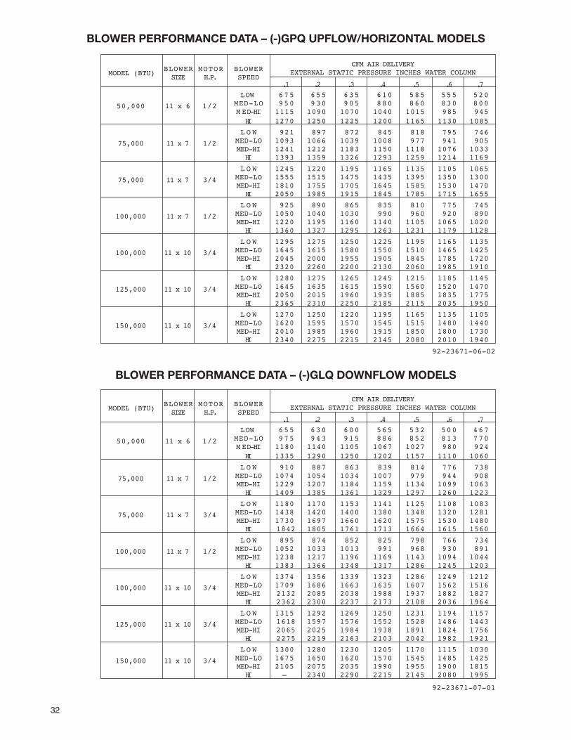
32
BLOWER PERFORMANCE DATA – (-)GPQ UPFLOW/HORIZONTAL MODELS
BLOWER PERFORMANCE DATA – (-)GLQ DOWNFLOW MODELS
MODEL (BTU)
.1 .2 .3 .4 .5 .6 .7
BLOWERSIZE
MOTORH.P.
BLOWERSPEED
CFM AIR DELIVERYEXTERNAL STATIC PRESSURE INCHES WATER COLUMN
LOW 675 655 635 610 585 555 520MED-LO 950 930 905 880 860 830 80050,000 11 x 6 1/2M ED-HI 1115 1090 1070 1040 1015 985 945
HI 1270 1250 1225 1200 1165 1130 1085
L O W 921 897 872 845 818 795 746MED-LO 1093 1066 1039 1008 977 941 90575,000 11 x 7 1/2MED-HI 1241 1212 1183 1150 1118 1076 1033
HI 1393 1359 1326 1293 1259 1214 1169
L O W 1245 1220 1195 1165 1135 1105 1065MED-LO 1555 1515 1475 1435 1395 1350 130075,000 11 x 7 3/4MED-HI 1810 1755 1705 1645 1585 1530 1470
HI 2050 1985 1915 1845 1785 1715 1655
L O W 925 890 865 835 810 775 745MED-LO 1050 1040 1030 990 960 920 890100,000 11 x 7 1/2MED-HI 1220 1195 1160 1140 1105 1065 1020
HI 1360 1327 1295 1263 1231 1179 1128
L O W 1295 1275 1250 1225 1195 1165 1135MED-LO 1645 1615 1580 1550 1510 1465 1425100,000 11 x 10 3/4MED-HI 2045 2000 1955 1905 1845 1785 1720
HI 2320 2260 2200 2130 2060 1985 1910
L O W 1280 1275 1265 1245 1215 1185 1145MED-LO 1645 1635 1615 1590 1560 1520 1470125,000 11 x 10 3/4MED-HI 2050 2015 1960 1935 1885 1835 1775
HI 2365 2310 2250 2185 2115 2035 1950
L O W 1270 1250 1220 1195 1165 1135 1105MED-LO 1620 1595 1570 1545 1515 1480 1440150,000 11 x 10 3/4MED-HI 2010 1985 1960 1915 1850 1800 1730
HI 2340 2275 2215 2145 2080 2010 1940
MODEL (BTU)
.1 .2 .3 .4 .5 .6 .7
BLOWERSIZE
MOTORH.P.
BLOWERSPEED
CFM AIR DELIVERYEXTERNAL STATIC PRESSURE INCHES WATER COLUMN
LOW 655 630 600 565 532 500 467MED-LO 975 943 915 886 852 813 77050,000 11 x 6 1/2M ED-HI 1180 1140 1105 1067 1027 980 924
HI 1335 1290 1250 1202 1157 1110 1060
L O W 910 887 863 839 814 776 738MED-LO 1074 1054 1034 1007 979 944 90875,000 11 x 7 1/2MED-HI 1229 1207 1184 1159 1134 1099 1063
HI 1409 1385 1361 1329 1297 1260 1223
L O W 1180 1170 1153 1141 1125 1108 1083MED-LO 1438 1420 1400 1380 1348 1320 128175,000 11 x 7 3/4MED-HI 1730 1697 1660 1620 1575 1530 1480
HI 1842 1805 1761 1713 1664 1615 1560
L O W 895 874 852 825 798 766 734MED-LO 1052 1033 1013 991 968 930 891100,000 11 x 7 1/2MED-HI 1238 1217 1196 1169 1143 1094 1044
HI 1383 1366 1348 1317 1286 1245 1203
L O W 1374 1356 1339 1323 1286 1249 1212MED-LO 1709 1686 1663 1635 1607 1562 1516100,000 11 x 10 3/4MED-HI 2132 2085 2038 1988 1937 1882 1827
HI 2362 2300 2237 2173 2108 2036 1964
L O W 1315 1292 1269 1250 1231 1194 1157MED-LO 1618 1597 1576 1552 1528 1486 1443125,000 11 x 10 3/4MED-HI 2065 2025 1984 1938 1891 1824 1756
HI 2275 2219 2163 2103 2042 1982 1921
L O W 1300 1280 1230 1205 1170 1115 1030MED-LO 1675 1650 1620 1570 1545 1485 1425150,000 11 x 10 3/4MED-HI 2105 2075 2035 1990 1955 1900 1815
HI — 2340 2290 2215 2145 2080 1995
*NOT TO BE USED AS A HEATING SPEED! 92-23671-07-01
*NOT TO BE USED AS A HEATING SPEED! 92-23671-06-02

33
LIMIT CONTROLThe high limit cut-off temperature is setat the factory and cannot be adjusted.The temperature setting prevents theair temperature leaving the furnacefrom exceeding the maximum outlet airtemperature, which, if exceeded, willshut the furnace down.
There are several reasons for a limitswitch to open and almost alwaysinvolve low airflow through the furnace.
1. A dirty or restricted air filter.
2. A dirty or restricted cooling coil.
3. Undersized or restricted return airsystem.
4. Undersized or restricted supply airsystem.
5. A problem affecting the mainblower:
A. A wrong speed tap selection.
B. Failing motor bearings.
C. Low voltage to the motor.
D. Dirty blower wheel.
E. Wrong motor rotation.
F. Blower wheel slipping on theF. motor shaft.
6. Overfiring the furnace with too muchgas pressure.
7. Ventilation problems.
FLAME ROLL-OUTSAFETY SWITCHESFurnaces are equipped with safetyswitches to protect against flame roll-out conditions in the burnercompartment, which, if tripped, willterminate the heating cycle. In theevent of a flame roll-out condition, theswitch will shut the furnace down.Switches for the (-)GPQ furnaces arelocated on either side of the burnercover plate and just above the burnerson the blower divider panel. The (-)GLQrequires only one switch on the left sideof burner cover plate. If a switch istripped, it must be manually reset. DONOT jumper or reset this switch. If thisswitch should trip, a qualified installer,service agency or the gas suppliershould be called to diagnose and/orcorrect the source of tripping. If thisunit is mounted in a closet, the doormust be closed when making thischeck.
PRESSURE SWITCHThis furnace is equipped with anormally-open pressure switch thatmonitors pressure conditions within thefurnace vent system during the heatingcycle.
There are several reasons for thepressure switch not to close.
1. An inoperative induced draft blower.
2. A loose or leaky pressure switchhose.
3. A blockage in the vent.
4. Severe downdrafts canceling thedraft from the inducer fan.
5. A leaky gasket at the induced draftblower.
6. Improperly sized or installed vent.
The pressure switch contacts mustopen before the unit can go throughanother heating cycle.
See troubleshooting chart in this bookfor troubleshooting recommendations.
SAFETY FEATURES

34
FIGURE 25FILTER RETAINING ROD
DISCONNECT MAIN ELECTRICALPOWER TO THE UNIT BEFOREATTEMPTING ANY MAINTENANCE.FAILURE TO DO SO CAN CAUSEELECTRICAL SHOCK RESULTINGIN SEVERE PERSONAL INJURY ORDEATH.
FILTERSFilter application and placement arecritical to airflow, which may affect theheating and cooling systemperformance. Reduced airflow canshorten the life of the systems majorcomponents, such as motor, limits,elements, heat exchanger, evaporatorcoil or compressor. Consequently, werecommend that the return air ductsystem have only one filter location.The most common location will beinside the furnace or air handler or afilter base. For systems with a returnair filter grill or multiple filter grills, canhave a filter installed at each of thereturn air openings. DO NOT DOUBLEFILTER THE RETURN AIR DUCTSYSTEM. DO NOT FILTER THESUPPLY AIR DUCT SYSTEM.
If high efficiency filters or electronic aircleaners are used in the system, it isimportant that the airflow is not
TABLE 10 FILTER SIZESMAINTENANCEWARNING!
*NOTE: Some filters must beordered or resized to fit certainunits and applications.
UPFLOW FILTER SIZES AS SHIPPED
FURNACE INPUT BOTTOM SIDE QUANTITYWIDTH BTUH SIZE SIZE
14 50 121/4" X 25" 153/4" X 25" 1171/2" 75 & 100 153/4" X 25" 153/4" X 25" 121" 100 191/4" X 25" 153/4" X 25" 1
241/2" 125 & 150 223/4" X 25" 153/4" X 25" 1
FILTERROD45-24095-01
IMPORTANT: Do not operate thesystem for extended periods withoutfilters. A portion of the dust entrainedin the air may temporarily lodge in theair duct runs and at the supplyregisters. Any circulated dust particleswill be heated and charred by contactwith the furnace heat exchanger. Thissooty residue will soil ceilings, walls,drapes, carpets, and other householdarticles. Soot damage may also resultwith, or without, filters in place, whencertain types of candles are burned, orcandlewicks are left untrimmed.
reduced to maximize systemperformance and life. Always verify thatthe systems airflow is not impaired bythe filtering system that has beeninstalled, by performing a temperaturerise and temperature drop test.
Keep the air filters clean at all times.Vacuum dirt from filter, wash withdetergent and water, air dry thoroughlyand reinstall.
See Table 10 and Figures 26 and 27 forproper filter sizes and locations.
1. 14”- 50,000 BTUH unit requiresremoval of 31/2” segment of filter andframe to get proper width for abottom filter.
2. 21”-100,000 BTUH unit requiresremoval of 31/2” segment of filter andframe to get proper width for a sidefilter.
3. 241/2”-125,000 and 150,000 BTUHunits require removal of 7” segmentof filter and frame to get proper width for a side filter.

35
FIGURE 26UPFLOW FILTER RETAINING ROD (SIDE RETURN)
FILTERROD45-24095-01
FILTER RODSUPPORTANGLEAE-60520-01
FILTER SUPPORTANGLE(SEE ANGLE DETAIL)AE-61883-01
FILTER RODSUPPORTANGLEAE-60520-01
FILTERSUPPORTANGLEAE-61883-01
CUT-OUT AND DRILL DETAILFILTER AND ROD ASSEMBLY
ROD & FILTER SUPPORT ANGLE ASSEMBLY
SOLID BOTTOM MAY BE ORDERED FROM THE FACTORY.
FIGURE 27DOWNFLOW FILTER INSTALLATION

36
SYSTEM OPERATIONINFORMATIONAdvise The Customer To:1. Keep the air filters clean. The heating
system will operate better, moreefficiently and more economically.
2. Arrange the furniture and drapes sothat the supply air registers and thereturn air grilles are unobstructed.
3. Close doors and windows. This willreduce the heating load on thesystem.
4. Avoid excessive use of kitchen &bathroom exhaust fans.
5. Do not permit the heat generated bytelevision, lamps or radios toinfluence the thermostat operation.
6 Except for the mounting platform,keep all combustible articles threefeet from the furnace and ventsystem.
7. IMPORTANT: Replace all blowerdoors and compartment covers afterservicing the furnace. Do not operatethe unit without all panels and doorssecurely in place.
8. Proper operation of the system withconstant air circulation.
COMBUSTIBLE MATERIAL MUSTNOT BE PLACED ON OR AGAINSTTHE FURNACE JACKET OR WITHINTHE SPECIFIED CLEARANCES OFTHE VENT PIPE. THE AREA AROUNDTHE FURNACE MUST BE KEPTCLEAR AND FREE OF ALLCOMBUSTIBLE MATERIALSINCLUDING GASOLINE AND OTHERFLAMMABLE VAPORS AND LIQUIDS.PLACEMENT OF COMBUSTIBLEMATERIALS ON, AGAINST ORAROUND THE FURNACE JACKETCAN CAUSE AN EXPLOSION ORFIRE RESULTING IN PROPERTYDAMAGE, PERSONAL INJURY ORDEATH. THE FURNACE OWNERSHOULD BE CAUTIONED THAT THEFURNACE AREA MUST NOT BEUSED AS A BROOM CLOSET OR FORANY OTHER STORAGE PURPOSES.
ANNUAL INSPECTIONThe furnace should operate for manyyears without excessive scale build-upin the flue passageways, however, it isrecommended that a qualified installer,service agency, or the gas supplieractually inspect the flue passageways,the vent system and the main burnersfor continued safe operation payingparticular attention to deterioration fromcorrosion or other sources.
HOLES IN THE VENT PIPE OR HEATEXCHANGER CAN CAUSE TOXIC
FUMES TO ENTER THE HOMERESULTING IN CARBONMONOXIDE POISONING OR DEATH.THE VENT PIPE OR HEATEXCHANGER MUST BE REPLACEDIF THEY LEAK.
• IMPORTANT: It is recommendedthat at the beginning of the heatingseason and approximately midwayin the heating season a visualinspection be made of the mainburner flames for the desired flameappearance by a qualified installer,service agency, or the gas supplier.
• IMPORTANT: It is alsorecommended that at the beginningof the heating season, the flamesensor be cleaned with steel woolby a qualified installer, serviceagency, or the gas supplier.
• IMPORTANT: It is recommendedthat an annual inspection andcleaning of all furnace markings bemade to assure legibility. Attach areplacement marking, which can beobtained through the distributor, ifany are found to be illegible ormissing.
IMPORTANT: FOR Nox MODELS –At the beginning of the heating seasona visual inspection of the Nox deviceshould be made to ensure they havenot become obstructed by insectsnests or anything else which mayeffect performance.
LUBRICATIONThe indoor blower motor and induceddraft motor are prelubricated by themotor manufacturer and do not requirefurther attention.
The motors must be cleanedperiodically by a qualified installer,service agency, or the gas supplier toprevent the possibility of overheatingdue to an accumulation of dust and dirton the windings or on the motorexterior. Air filters should be keptclean. Dirty filters can restrict airflowand results in motor overheating.
Reference Figure 28 for properremoval of the blower assembly ondownflow models.
REPLACEMENT PARTSContact your local distributor for acomplete parts list.
NOx MODELSWhen converting furnaces equippedwith NOx inserts to LP gas, remove theNOx insert assemblies.
TROUBLESHOOTINGRefer to Figure 29 for determiningcause of unit problems.
WIRING DIAGRAMFigures 30 and 31 are complete wiringdiagrams for the furnace and powersources.
WARNING!
WARNING!
FIGURE 28DOWNFLOW BLOWER REMOVAL

37
➤ FIGURE 29INTEGRATED FURNACE CONTROL (IFC) TROUBLESHOOTING GUIDEFOR UTEC 1095-101

38
FIGURE 30TROUBLESHOOTING FLOWCHART (CONTINUED)
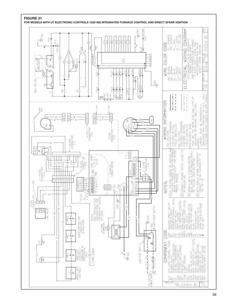
39
FIGURE 31FOR MODELS WITH UT ELECTRONIC CONTROLS 1028-928 INTEGRATED FURNACE CONTROL AND DIRECT SPARK IGNITION

40 CM 1105