force tracking impedance control with variable target...
TRANSCRIPT
Force Tracking Impedance Control withVariable Target Stiffness
K. Lee and M. Buss ∗
∗ Institute of Automatic Control Engineering,Technische Universitat Munchen, Munich, 80290 Germany
(E-mail: [email protected])
Abstract: In this paper, a novel force tracking impedance control strategy is presented in whichtarget stiffness is varied on-line to regulate the desired contact force without any knowledgeof the environment. Humans can control contact force by adjusting their arm stiffness. Thecontact force can be either increased by making one’s arm stiffer or decreased by reducing thearm stiffness. Furthermore, humans can keep the force tracking error within a certain rangewithout any knowledge of environmental parameters as long as how much force they exerton the object is known to them. Analogously, the proposed control scheme achieves a contactforce regulation control by adjusting the target stiffness of the impedance control. The new forcetracking impedance control scheme does not require estimating environment stiffness or locationssince the controller is adapted only based on the previous force tracking error between the desiredand real contact force. Stability of the proposed scheme is discussed with a quadratic Lyapunovfunction. Extensive simulation studies with a 7 degree of freedom (DoF) robot manipulatorusing full arm dynamics are conducted to demonstrate the validity of the proposed scheme.
1. INTRODUCTION
As robot manipulators have evolved and their applicationshave been broadened, interaction (compliance) control ofrobot manipulators with stiff environments or objects hasbecome a key component for the success of many manipu-lation tasks. Typical applications of the compliance controlare deburring, assembling, grinding, and surface finishingtasks, etc. Due to the central importance of such compliantmotions for robot manipulators, vast investigations havebeen made on this challenge over the past two decades re-sulting in two basic classes: hybrid position/force control,e.g. Raibert et al. (1981); Khatib. (1987), and impedancecontrol, e.g. Hogan. (1985, 1988).The hybrid position/force control is suitable where theenvironments are well structured and their geometrical in-formation is previously known, since this strategy allows tocontrol positions in unconstrained directions and interac-tion forces in constrained directions explicitly as requiredin many applications. However, it requires to decomposethe task space of the manipulator into two subspaces: aposition space and a force space corresponding to thoseend-effector (EEF) directions of which either the positionor the interaction force is to be controlled, respectively.Therefore, it may not be a promising approach for un-structured and dynamically changing environments.Alternatively, the impedance control strategy providescompliant manipulator motions in a unified framework forboth constrained and unconstrained directions. The coreof the impedance control is to regulate dynamic responseof the EEF to interaction forces by establishing a suitablevirtual mass-spring-damper system on the EEF. Althoughthe impedance control scheme can provide a unified frame-work for both constrained and unconstrained motion con-trol problems, an explicit interaction force control can not
be achieved since it controls the interaction force indirectlyby regulating the dynamic relationship between the EEFposition and the interaction force. Therefore, the inabilityof the impedance control strategy to achieve force track-ing control has been considered as a major disadvantagecompared to hybrid position/force control.As a remedy to this issue, many efforts have been made toachieve force tracking control within the impedance con-trol framework. Some researchers introduce a sliding modetype of control based on the impedance control schemeto achieve force tracking characteristics for autonomousrobots as well as teleoperation systems, see e.g. Hace et al.(1997); Cho et al. (2001); Iwasaki et al. (2003). Seraji et al.(1997) present an adaptive control scheme that generatesa desired trajectory in order to regulate a desired contactforce either based on the estimation of the environmentalstiffness and location or without the estimation. Chanet al. (1991) proposes a variable structure control schemebased on precise environmental knowledge (stiffness andposition of objects) for the robust impedance control un-der parametric uncertainties and external disturbances.In practical cases, however, the location and stiffness ofenvironment are usually unknown and difficult to estimateaccurately. Furthermore, an inaccurate estimation of theseparameters usually leads to a large force tracking error.Jung et al. (2004) propose an adaptive impedance controlin which null stiffness is assigned for the constrained mo-tion control to guarantee a zero force tracking error com-bined with an adaptive control feature which makes thesystem robust to the uncertainties in both robot dynamicsand environment parameters.However, considering human force control capabilitieswhen exerting a certain force on a digital scale, neither nullstiffness nor variation of the desired trajectory is naturaland intuitive. While one’s hand is in contact with the en-
Proceedings of the 17th World CongressThe International Federation of Automatic ControlSeoul, Korea, July 6-11, 2008
978-1-1234-7890-2/08/$20.00 © 2008 IFAC 6751 10.3182/20080706-5-KR-1001.2474

vironment, the desired trajectory of the hand or the exactknowledge of environment stiffness is not required. On theother hand, one cannot exert contact forces with null armstiffness. Thus, suitable force tracking impedance controlschemes should consider the fact that humans control theforce exerted on an object by adapting their arm stiffness.The objective of this study is to develop an intuitive andanthropomorphic force tracking control scheme within theimpedance control framework. The main idea is to adaptthe target stiffness of the impedance controller accordingto force tracking errors. Since the adaptation of the targetstiffness depends only on the previous force tracking error,the knowledge of the environment stiffness is not required.Thus, the proposed force tracking impedance control issimple and robust to environmental parameter variation.This paper is structured as follows. Section 2 reviewsbriefly the conventional impedance control and a novelforce tracking impedance control scheme with variablestiffness is developed. Stability and force tracking errorsof the proposed control scheme are discussed in Section 3.Intensive dynamic simulations are presented in Section 4to demonstrate the efficiency of the proposed scheme forvarious environments including variations of the environ-mental parameters. Section 5 describes the conclusionsdrawn from this work.
2. FORCE TRACKING IMPEDANCE CONTROL
A position based impedance control is one of the most typ-ical compliance control schemes which is briefly reviewedin the Section 2.1. It is modified with variable stiffness fora force tracking impedance control scheme in Section 2.2.
2.1 Position based impedance Control
A position based impedance control scheme consists ofan inner position control loop and an outer indirect forcecontrol loop, see Fig. 1. In free space motion (zero contactforces F ), the desired trajectory Xd is identical to thecompliant trajectory Xc since no compliant motions arenecessary. In constrained motions, however, a nonzerocontact force modifies the desired trajectory in the outerimpedance control loop resulting in the compliant desiredtrajectory, which is to be tracked by the inner motioncontrol loop. One of the common formulations for thetarget impedance is
MXdc +BXdc +KXdc = F, (1)whereM , B,K are n×n constant diagonal mass, damping,and stiffness matrices of the target impedance for an n-dimensional task space; F and Xdc denote the contactforce and the corresponding desired trajectory modifica-tion (Xd −Xc) by the impedance controller, respectively.
MotionControl
ImpedanceControl
Robot/Environment
ForwardKinematics
Fig. 1. Position based impedance control strategy: Xd, Xc,andX are the desired, compliant, and EEF trajectory,respectively. F is the measured force.
For simplicity, we consider a one dimensional case as shownin Fig. 2-(a), in which an EEF of a robot manipulator onlyjust contacts with a wall without generating a contactforce. It can be easily extended to the entire task spacewithout loss of generality. In this case, (1) is reduced to
mx+ bx+ k(xd − xc) = f. (2)
Further, assuming good tracking performance of the innerposition control loop, the compliant trajectory xc can bereached by the EEF (xc = x). Then the contact force atthe steady state
f = k(xd − xc) (3)
can be calculated. Representing the environment by alinear spring model with stiffness ke, the contact force canbe alternatively expressed by
f = ke(x− xe). (4)
Substituting x (= xc) from (4) into (3), the steady statecontact force can be rewritten as
f =kke
k + ke(xd − xe). (5)
Since the wall position xe and stiffness ke are environmentparameters, (5) reveals two possible strategies to controlthe contact force; by tuning either 1) the desired trajec-tory xd or 2) the target stiffness k. However, a desiredtrajectory planning that guarantees force tracking in theconstrained space is not intuitive. Moreover, it can benoted that small numerical errors in the calculation of xd
will be multiplied by the resulting stiffness ( kke
k+ke) leading
to significant force tracking errors. On the contrary, thecontact force controllability can be improved by controllingthe target stiffness that affects the contact force in har-monic mean fashion ( kke
k+ke) incorporating the environment
stiffness ke.One interesting thing to be noticed here is negative targetstiffness. When the desired trajectory xd is set to penetratethe wall location xe far enough, i.e., reaching xd generatesa contact force greater than the desired contact force fd,then a positive stiffness modifies xd in the same direction ofthe contact force f by (3). However, when the penetrationof xd in xe is not deep enough, i.e., even reaching xd
can only produce a contact force f smaller than thedesired force fd, the positive stiffness will not help atall. In this case, one needs a negative stiffness which canmodify the desired trajectory xd in the opposite directionto the contact force. Fig. 2-(b) shows a modification ofthe desired trajectory versus target stiffness. From theabove observations, a force tracking impedance control is
wall
a) b)
Fig. 2. Robot EEF contacting with a wall (a), and stiffnessversus desired trajectory modification ∆x at a givencontact force 10[N ] (b)
17th IFAC World Congress (IFAC'08)Seoul, Korea, July 6-11, 2008
6752

MotionControl
Robot/Environment
ForwardKinematics
Impedance Filter
Fig. 3. Position based force tracking impedance controlwith variable parameters
developed in the next section with variable stiffness of thetarget impedance.
2.2 Impedance Control with variable stiffness
The idea is simple, intuitive, and anthropomorphicallyinspired. Consider a hand in contact with a wall. Inorder to exert more force, humans make their arm stiffer,whereas they make it softer when the contact force shouldbe reduced. It means the arm stiffness is adapted to thedifference of a desired and actual contact force. In order toimitate this human force control capability, an impedancecontrol with variable target stiffness is proposed. Thecorresponding impedance equation can be written as
mxdc + bxdc + k(t)xdc = f. (6)
for the one dimensional case. Thereby, b denotes a constantdamping coefficient, and the stiffness k(t) is adapted toforce tracking errors to minimize them. The resulting forcetracking impedance control scheme is illustrated in Fig. 3.Denoting the force tracking error ef as
ef = fd − f, (7)
the adaptation of k(t) is defined as
k(t) = αk0x−1dc , (8)
withα = kfef + kv ef . (9)
Thereby kf and kv denote a constant proportional anddifferential gain for the force tracking control, respectively.Substituting (6) into the force tracking error ef , (7) canbe written as
ef = fd −mxdc − bxdc − k(t)xdc. (10)
Combining (10) with the proposed force control law (8)and (9) yields the force tracking error dynamics
ef = fd −mxdc − bxdc − k′fef − k′v ef (11)
⇒ k′v ef + (k′f + 1)ef = fd −mxdc − bxdc (12)
with k′f = k0kf and k′f = k0kv. Consequently, the steadystate force tracking error becomes
ef,ss =fd
k′f + 1=
fd
k0kf + 1. (13)
From (13), it is noted that the proposed control does notprovide a zero force tracking error for none zero desiredforce. However, the presented method can guarantee tokeep steady state force tracking error below the measure-ment resolution of conventional load cells. For instance,the steady state force tracking error ef,ss is smaller than10−4 N for kf=103, k0=103 N/m, and fd =100 N.
On the other hand, as mentioned in the previous section,it is not possible to obtain the desired contact force fd
with a positive target stiffness for some cases. Consider xd
does not penetrate enough in xe such that the maximumachievable contact force f is smaller than the desiredcontact force fd; fd > f = ke(xd − xe). In this case, thenegative target stiffness can modify the desired trajectoryxd such that the compliant trajectory xc can furtherpenetrate xe such that the desired force can be achieved.The proposed scheme does not pose any limit on the sign ofthe target stiffness so that the time varying target stiffnessk(t) may have a negative sign depending on the sign ofα. Since neither negative nor time varying target stiffnessis widely adopted in robotics, stability of the proposedscheme is discussed in the next section.
3. STABILITY OF TIME VARYING IMPEDANCECONTROL
The proposed impedance controller with variable targetstiffness in (6) is a specific case of
m(t)xdc + b(t)xdc + k(t)xdc = f (14)which can be characterized as a second order linear timevarying system. Thereby m(t) and b(t) are time varyingpositive inertia and damping coefficients, and k(t) timevarying stiffness. Since such systems are of significantimportance in control theory many efforts have been madeto provide explicit stability condition, see e.g., Harris.(1980); Rugh. (1996); Slotine. (1991); Gil. (2005). Many ofthose stability analyses assume slowly varying and positivedefinite parameters. Hence, these analyses can not applyto the proposed scheme and new stability analysis shouldbe devised.Consider a force regulation problem (fd =const.) with amore general linear time varying system (14). For obtain-ing a force tracking control the proposed control law (6)-(9) is applied to (14). In order to analyze the stability, wedefine the positive scalar Lyapunov function candidate
V =12mx2 +
12ke(x− xe)2 +
12kne
2f , (15)
where the argument t is dropped. Thereby kn is a nominalpositive stiffness which will be defined later and m is atime varying positive inertia. It is noted that the Lyapunovfunction candidate can be interpreted as a sum of kineticand potential energy for the motion control and the forcetracking control. Next, we assume a constant positiontracking error δx in the inner motion control loop xc =x + δx and a constant desired trajectory xd, (14) can berewritten as
mx = −fd − bx+ k′f (ef + 1) + k′v ef . (16)Furthermore, due to the constant desired force fd, theforce tracking error ef and its first time derivative can bewritten with a linear environment model f = ke(x − xe)as
ef = fd − f = fd − ke(x− xe), (17)
ef = −f = −kex, (18)for a flat environment xe = 0.
On the other hand, the time differentiation of (15) gives
V =12mx2 +mxx+ ke(x− xe)x+ knef ef , (19)
17th IFAC World Congress (IFAC'08)Seoul, Korea, July 6-11, 2008
6753
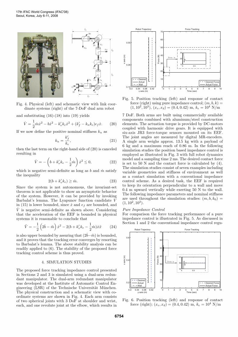
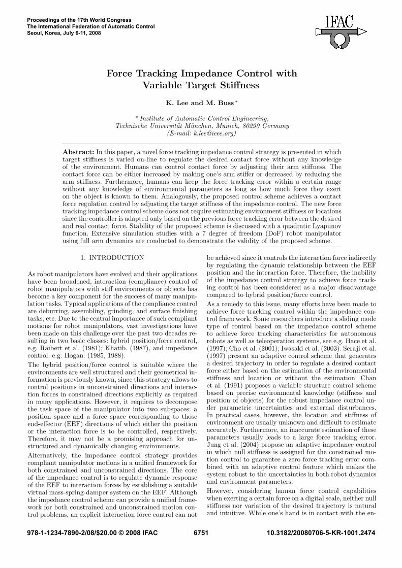
Fig. 4. Physical (left) and schematic view with link coor-dinate systems (right) of the 7-DoF dual arm robot
and substituting (16)-(18) into (19) yields
V =12mx2 − bx2 − k′vkex
2 + (k′f − knke)ef x. (20)
If we now define the positive nominal stiffness kn as
kn =k′fke, (21)
then the last term on the right-hand side of (20) is canceledresulting in
V = −(b+ k′vke −
12m
)x2 ≤ 0, (22)
which is negative semi-definite as long as b and m satisfythe inequality
2(b+ k′vke) ≥ m. (23)
Since the system is not autonomous, the invariant-settheorem is not applicable to show an asymptotic behaviorof the system. However, it can be provided by invokingBarbalat’s lemma. The Lyapunov function candidate Vin (15) is lower bounded, since x and ef are bounded, andV is negative semi-definite as shown above. Consideringthat the acceleration of the EEF is bounded in physicalsystems it is reasonable to conclude that
V = −12
(2b− m
)x2 − 2(b+ k′vke −
12m)xx (24)
is also upper bounded by assuring that (2b−m) is bounded,and it proves that the tracking error converges by resortingto Barbalat’s lemma. The above stability analysis can bereadily applied to (6). The stability of the proposed forcetracking control scheme is thus proved.
4. SIMULATION STUDIES
The proposed force tracking impedance control presentedin Sections 2 and 3 is simulated using a dual-arm redun-dant manipulator. The dual-arm redundant manipulatorwas developed at the Institute of Automatic Control En-gineering (LSR) of the Technische Universitat Munchen.The physical construction and a schematic view with co-ordinate systems are shown in Fig. 4. Each arm consistsof two spherical joints with 3 DoF at shoulder and wrist,each, and one revolute joint at the elbow, which results in
Fig. 5. Position tracking (left) and response of contactforce (right) using pure impedance control; (m, b, k) =(1, 102, 103), (xe, xd) = (0.4, 0.42) m, ke = 104 N/m
7 DoF. Both arms are built using commercially availablecomponents combined with aluminum/steel constructionelements. The actuation torque is provided by DC-motorscoupled with harmonic drive gears. It is equipped withsix-axis JR3 force-torque sensors mounted on its EEF.The joint angles are measured by digital MR-encoders.A single arm weighs approx. 13.5 kg with a payload of6 kg and a maximum reach of 0.86 m. In the followingsimulation studies the position based impedance control isemployed as illustrated in Fig. 3 with full robot dynamicsmodel and a sampling time 2 ms. The desired contact forceis set to 50 N and the contact force is calculated by (4).The simulation studies consist of seven examples includingvariable geometries and stiffness of environment as wellas a contact simulation with a conventional impedancecontrol scheme. As a desired task, the EEF is requiredto keep its orientation perpendicular to a wall and move0.4 m upward vertically while exerting 50 N to the wall.The following impedance parameters and nominal stiffnessare used throughout the simulation studies: (m, b, k0) =(1, 102, 103).
Pure Impedance ControlFor comparison the force tracking performance of a pureimpedance control is illustrated in Fig. 5. As discussed inSection 1 and 2 the conventional impedance control regu-
Fig. 6. Position tracking (left) and response of contactforce (right); (xe, xd) = (0.4, 0.42) m, ke = 104 N/m
17th IFAC World Congress (IFAC'08)Seoul, Korea, July 6-11, 2008
6754

Fig. 7. Position tracking (left) and response of contactforce (right); (xe, xd) = (0.4, 0.401) m, ke = 104 N/m
lates dynamic response of the EEF corresponding to thecontact force. Therefore, it is intrinsically inappropriate forforce tracking control and the force tracking error in thissimulation is greater than 30 N. When the environmentstiffness ke is exactly known, although it is practicallyunrealistic, the difference between the desired and actualcontact forces in Fig. 5 can be compensated by replanningthe desired trajectory xd.
Force Control with Constant xe and ke
In this simulation, the proposed scheme guarantees po-sition tracking in unconstrained (x-) direction while thedesired force is achieved in constrained (y-) direction asillustrated in Fig. 6. At the initial configuration, the EEFmakes a just contact (f = 0) with a flat wall placed atxe = 0.4 m. The force tracking control gains kf and kv areset to 103 and 26, respectively, and the target impedanceparameters are selected as M = I, B = 102 · I, andK0 = 103 · I. In this simulation, the force tracking error atthe steady state ef,ss is identical to the force tracking errorwhich is calculated by (13): ef,ss = fd
k0kf +1 < 5 × 10⁻⁵.Since it is far smaller than the measurement resolutionof conventional load cells, it can be practically treated aszero.
Force Control with Negative StiffnessAs discussed in Section 3, if the desired trajectory xd is
Fig. 8. Position tracking (left) and response of contactforce (right); (xe, xd) = (0.4, 0.41) m
Fig. 9. Position tracking (left) and response of contactforce (right); xd = 0.44 m, ke = 104 N/m
not placed deep enough into xe, even reaching xd cangenerate contact force f which is smaller than fd. Sincethe positive target stiffness can only modify the desiredtrajectory in the same direction with the contact force freducing the penetration depth xc − xe, the desired forcecan not be achieved. In this case, the negative stiffnessmodifies the desired trajectory to opposite direction of thecontact force such that the compliant trajectory xc willpenetrate further into xe. Thus, the desired contact forcefd can be achieved. Fig. 7 illustrates such kind of forcetracking performance when the desired trajectory is set toxd = 0.401 m which is slightly greater than xe = 0.4 m.In this case, reaching xd can only generate contact forcesmall than the desired one (f < fd). However, negligibleforce tracking errors could be obtained by the proposedscheme with negative stiffness and the force tracking erroris identical to that of the previous simulation. Further, it isobserved that the impact force during the transient phasefrom the free space motion to the constrained motion ismuch smaller than that of the previous simulation. In thissimulation, the target impedance parameters are set toM = I, B = 102 · I, and K0 = 103 · I, and the gainskf = 103 and kv = 26 for the force tracking controller.
Variable Environmental StiffnessIn this simulation, the environment stiffness ke changesabruptly from 2×10⁴ N/m to 104 N/m at t = 5 s. Since the
Fig. 10. Position tracking (left) and response of contactforce (right); xd = 0.41 m, ke = 104 N/m
17th IFAC World Congress (IFAC'08)Seoul, Korea, July 6-11, 2008
6755

Fig. 11. Position tracking (left) and response of contactforce (right); xd = 0.42 m
proposed force tracking scheme adapts the target stiffnessonly based on the previous force tracking error, the samesteady state force tracking error is achieved for both caseswith different environment stiffness, see Fig. 8. The targetimpedance parameters are selected as M = I, B = 102 · I,and K0 = 103 · I, and force tracking gains as kf = 103 andkv = 26. Due to the change of the environment stiffnesske, the contact force f is perturbed at t = 5 s but it hassettled to the desired contact force in a very short time.This simulation results show the proposed force trackingcontrol is robust to sudden changes of the environmentalstiffness while guaranteeing negligible force tracking errors.
Variable Environmental GeometryIn practical cases, the wall is not flat, hence the forcetracking control should cope with surface variation ofthe environment. In this simulation, the proposed forcetracking control scheme is applied to two different unevenenvironment surfaces which have a triangular type ofindent and burr. The results of this simulation are shownin Fig. 9 for the triangular type of indent, and Fig. 10for the burr type of environment surface, respectively.For both cases, it is indicated that the proposed schememaintains the desired contact force with negligible forcetracking errors throughout the task and is thus robust tovariations in the geometry of the surface. Furthermore, itcan be observed that the proposed force tracking controldoes not show any difference in steady state force trackingerrors between the flat part and inclined part of the wall.
Variable Environmental Stiffness and GeometryIn this simulation, the proposed scheme is tested in thepresence of both abrupt change of the environment stiff-ness from 2× 10⁴ N/m to 1× 10⁴ at t = 5 s and the trian-gular type of burr in the surface. The target impedanceparameters are selected as M = I, B = 102 · I, andK0 = 103 · I, and force tracking gains as kf = 103 andkv = 26. Due to the overlap of the abrupt change of theenvironment stiffness and geometry at t = 5 s, relativelylarge impact force is observed, but it has settled in a veryshort time to the desired contact force fd and negligiblesteady state force tracking errors are achieved.
5. CONCLUSION
In this paper, a simple and intuitive force tracking con-trol scheme is presented within the impedance control
framework imitating human force tracking capabilities.The impedance control scheme adapts its target stiffnessaccording to the previous force tracking error resultingin a second order linear time varying system. The pro-posed control scheme utilizes even negative stiffness toachieve force tracking control. Stability analysis is givenfor more general second order linear time varying systemswhere variable target inertia, damping, and stiffness areemployed. Extensive simulations have been conducted forvarious situations including uneven environment surfacesand abrupt changes of environment stiffness. Simulationresults prove the force tracking capability of the proposedcontrol scheme for various situations without knowing theenvironment stiffness.
REFERENCES
M. Raibert and J. Craig. Hybrid Position/Force Controlof Manipulators. ASME J. of Dyn. Sys. Meas. Control,102(2), 126-133, 1981.
O. Khatib. A Unified Approach for Motion and ForceControl of Robotic Manipulators. IEEE J. Robot.Automat, 3(1), 43-53, 1987.
N. Hogan. Impedance Control: An Approach to Manip-ulator. ASME J. of Dyn. Sys. Meas. Control, 107(1),1-24, 1985.
N. Hogan. On the Stability of Manipulators PerformingContact Tasks. IEEE J. of Robot. Automat., 4(6), 677-686, 1988.
T. Lasky and T. Hsia. On Force-Tracking ImpedanceControl of Robot Manipulators. Proc. IEEE Int. Conf.Robot. and Automat, Los Alamitos, CA, 274-280, 1991.
H.-C. Cho, J.-H. Park, K.-H. Kim, and J.-O. Park. Sliding-Mode-Based Impedance Controller for Bilateral Tele-operation under Varying Time-Delay. Proc. IEEE Int.Conf. Robot. and Automat, Seoul, Korea, 21-26, 2001.
M. Iwasaki, N. Tsujiuchi, and T. Koizumi. Adaptive forcecontrol for unknown Environment using sliding modecontroller with variable hyperplane. JSME Int. J. SeriesC, Mech. Syst. machine elements and manufacturing,46(3), 967-972, 2003.
Chan. S. et al. Robust Impedance Control of RobotManipulators. Int. J. of Robot. Automat., 6(4), CA,220-227, 1991.
H. Seraji and R. Colbaugh. Force Tracking in ImpedanceControl. Int. J. of Robotic Research, 16(1), 97-117, 1997.
S. Jung, T.C. Hsia, and R.G. Bonitz Force Track-ing Impedance Control of Robot Manipulators underUnknown Environment. IEEE. Trac. Control SystemTechn., 12(3), 474-483, 2004.
A. Hace, S. Uran, K. Jezernik, and B. Curk. Robust SlidingMode Based Impedance Control. Proc. IEEE Int. Conf.Intell. Engnrg. Sys., 77-82, 1997.
C. J. Harris and J. F. Miles. Stability of Linear Systems.New York, Academic Press, 1980.
W. J. Rugh. Linear System Theory. Upper Saddle River,New Jersey, Prentice Hall, 1996.
M. I. Gil. Stability of Linear Systems Governed by SecondOrder Vector Differential Equations. Int. Journal ofControl, 534-536, 78(7), 2005.
J. J. Slotine and W. Li. Applied Nonlinear Control.Englewood Cliffs, New Jersy, Prentice Hall, 1991.
17th IFAC World Congress (IFAC'08)Seoul, Korea, July 6-11, 2008
6756