fy2000 progress report for combustion and emission control ... · progress report for combustion...
TRANSCRIPT

U.S. Department of EnergyOffice of Transportation Technologies1000 Independence Avenue, S.W.Washington, DC 20585-0121
FY 2000
Progress Report for Combustion and Emission Control for Advanced CIDI Engines
Energy Efficiency and Renewable EnergyOffice of Transportation Technologies
Approved by Steven Chalk
November 2000

Combustion and Emission Control for Advanced CIDI Engines FY 2000 Progress Report
CONTENTS
Page
iii
I. INTRODUCTION . . . . . . . . . . . . . . . . . . . . . . . . . . . . . . . . . . . . . . . . . . . . . . . . . . . . . . . . . . . . .1
II. EMISSION CONTROL SUBSYSTEM DEVELOPMENT. . . . . . . . . . . . . . . . . . . . . . . . . . . .9
A. Emission Control Subsystem Evaluation for Light-Duty CIDI Vehicles . . . . . . . . . . . . . . . . . . . . . . . . . . . . . . . 9
B. Application of Advanced Emission Control Sub-Systems to State-of-the-Art Diesel Engines. . . . . . . . . . . . . . 15
III. IN-CYLINDER COMBUSTION STUDIES, ADVANCED COMBUSTION RESEARCH, SENSORS, AND DIAGNOSTICS . . . . . . . . . . . . . . . . . . . . . . . . . . . . . . . . . . . . . . . . . . . . . . .19
A. Heavy-Duty Diesel Engine Combustion: Diffusion-Flame/Wall Interactions . . . . . . . . . . . . . . . . . . . . . . . . . . 19
B. Development of a Combined Mass Flow Rate and Chemical Composition Sensor for the Intake of CIDI Engines Using Thin Film MEMS Sensors. . . . . . . . . . . . . . . . . . . . . . . . . . . . . . . . . . . . . . . . . . . . . . . . . . . . . . . . . . . . . 24
C. Advanced CIDI Engine Diesel Combustion R&D . . . . . . . . . . . . . . . . . . . . . . . . . . . . . . . . . . . . . . . . . . . . . . . 27
D. Extending Exhaust Gas Recirculation Limits in CIDI Engines . . . . . . . . . . . . . . . . . . . . . . . . . . . . . . . . . . . . . . 34
E. Measuring the Cylinder-to-Cylinder Distribution of Recirculated Exhaust Gas during Transient Operation of a CIDI Engine . . . . . . . . . . . . . . . . . . . . . . . . . . . . . . . . . . . . . . . . . . . . . . . . . . . . . . . . . . . . . . . . . . . . . . . . . . . . . 40
F. Pressure Reactive Variable Compression Ratio Piston Development . . . . . . . . . . . . . . . . . . . . . . . . . . . . . . . . . 45
G. HCCI Combustion Fundamentals: In-Cylinder Diagnostics and Kinetic-Rate Computations . . . . . . . . . . . . . . 50
H. Camless Variable Valve Timing System for a High-speed CIDI Engine . . . . . . . . . . . . . . . . . . . . . . . . . . . . . . 56
I. Low-Friction Coatings for CIDI Fuel Injection System Components . . . . . . . . . . . . . . . . . . . . . . . . . . . . . . . . . 60
J. Fuel Spray Measurement Using X-Rays . . . . . . . . . . . . . . . . . . . . . . . . . . . . . . . . . . . . . . . . . . . . . . . . . . . . . . . 65
IV. EXHAUST GAS NOX EMISSION CONTROL R&D . . . . . . . . . . . . . . . . . . . . . . . . . . . . . .69
A. Non-Thermal Plasma-Assisted Catalysis. . . . . . . . . . . . . . . . . . . . . . . . . . . . . . . . . . . . . . . . . . . . . . . . . . . . . . . 69
B. Sulfur-Tolerant NOx Adsorber System Development. . . . . . . . . . . . . . . . . . . . . . . . . . . . . . . . . . . . . . . . . . . . . 75
C. Reduction of NOx Emissions for Lean-Burn Engine Technology . . . . . . . . . . . . . . . . . . . . . . . . . . . . . . . . . . . 78
V. EXHAUST GAS PARTICULATE EMISSION CONTROL R&D . . . . . . . . . . . . . . . . . . . .87
A. Optical Diagnostic Development for Exhaust Particulate Matter Measurements . . . . . . . . . . . . . . . . . . . . . . . . 87
B. Diesel Particle Scatterometer . . . . . . . . . . . . . . . . . . . . . . . . . . . . . . . . . . . . . . . . . . . . . . . . . . . . . . . . . . . . . . . . 92
C. The Effect of Injector and In-Cylinder Conditions on Soot Formation in CIDI Engines . . . . . . . . . . . . . . . . . . 96
D. Microwave-Regenerated Exhaust Particulate Filter Technology . . . . . . . . . . . . . . . . . . . . . . . . . . . . . . . . . . . 100

Combustion and Emission Control for Advanced CIDI Engines FY 2000 Progress Report
1
I. INTRODUCTION
Developing Advanced Combustion and Emission Control Technologies
On behalf of the Department of Energy’s Office of Transportation Technologies (OTT), we are pleased to introduce the Fiscal Year (FY) 2000 Annual Progress Report for the Advanced Combustion and Emission Control Research and Development (R&D) Program. The Program is focused on the compression ignition, direct injection (CIDI) engine, an advanced version of the commonly known diesel engine, which is used in both light- and heavy-duty vehicles. Both the Office of Advanced Automotive Technologies (OAAT) and the Office of Heavy Vehicle Technologies (OHVT) conduct CIDI engine R&D and have coordinated their research plans to minimize overlap and maximize the use of available R&D funding. This year’s accomplishment report represents the output of this combined effort.
This introduction serves to briefly outline the nature, progress, and future directions of the Combustion and Emission Control for Advanced CIDI Engines R&D Program. Together with DOE National Laboratories and in partnership with private industry and universities across the United States, OTT engages in high risk research and development that provides enabling technology for fuel efficient and environmentally-friendly light- and heavy-duty vehicles. The work conducted under this Program relies on the DOE Advanced Petroleum-Based Fuels Program to provide on-going reformulated diesel fuel developments, to enable meeting our out-year objectives. (The APBF Program is described in a separate report.)
The Combustion and Emission Control for Advanced CIDI Engines R&D Program supports the Partnership for a New Generation of Vehicles (PNGV), a government-industry partnership striving to develop, by 2004, a mid-sized passenger vehicle capable of achieving 80 miles per gallon while adhering to future emissions standards and maintaining such attributes as affordability, performance, safety, and comfort. In 1997, following a rigorous process of technology down-selection, PNGV targeted CIDI engines as one of the promising technologies for achieving the 80 miles per gallon fuel economy in a light-weight hybrid vehicle. As scheduled in 2000, Ford, General Motors, and Daimler-Chrysler all delivered PNGV concept cars. All three of these concept cars used CIDI engines. Today’s CIDI engines achieve impressive thermal efficiency; however, in order to meet future emissions standards, advancements in clean combustion, emission control technology and diesel fuels
Kathi Epping, Program Manager
Gurpreet Singh, Program Manager
Kenneth Howden, Program Manager
PNGV Concept Cars

Combustion and Emission Control for Advanced CIDI Engines FY 2000 Progress Report
2
are necessary. Similar to PNGV, the DOE/OHVT Light Truck goal is to increase the fuel efficiency of light trucks by 35 percent by 2004, while meeting emission standards that apply to both cars and light trucks. Because the emission challenges facing CIDI engines are very similar for both light- and heavy-duty vehicle applications, OAAT and OHVT have co-funded many of the projects whose reports are contained herein.
The Advanced Combustion and Emission Control R&D Program explores the fundamentals of combustion, how emissions are formed, and advanced methods for treating those emissions. Testing and modeling are also important elements of the program and enable us to evaluate potential technology and validate technology selection and direction. By working at the forefront of these new technologies, we hope to enhance the knowledge base that can be used by automotive partners and suppliers (engine manufacturers, catalyst companies, etc.) to develop advanced automotive systems.
Our program, which is cost-shared between industry and government, is sharply focused on improving combustion processes and emission control technologies. Progress in these areas will help overcome the critical technical barriers associated with the emission challenges of highly efficient CIDI engines, namely, higher than desired levels of nitrogen oxides (NO
x
) and particulate matter (PM) in the exhaust.
Technical Leadership
By providing strong technical direction and program and financial management, DOE has taken a leadership role in the development of technology to reduce exhaust emissions of highly efficient diesel engines while minimizing compromises in cost, performance and efficiency. DOE could not provide this leadership without the cooperative assistance of General Motors, DaimlerChrysler and Ford through participation in PNGV technical teams and the Low Emission Partnership (LEP). CIDI R&D in the OHVT is linked to PNGV through the DOE Diesel Cross-Cut Team, and receives cooperative assistance from DDC, Cummins, Caterpillar, and Navistar. The technology developed under our program will help the automakers overcome a critical barrier to producing light-duty passenger cars with up to three times the fuel economy of today’s conventional vehicles and light-duty trucks that are at least 35 percent more efficient while meeting strict emissions standards established by the Environmental Protection Agency (EPA) and the California Air Resources Board (CARB).
The Development of High-Efficiency, Low-Emission CIDI Engines Requires Simultaneous Development of Clean Combustion, Emission Control Devices, and Advanced Fuels
Advanced Combustion and Emission Control Participants

Combustion and Emission Control for Advanced CIDI Engines FY 2000 Progress Report
3
The unique scientific capabilities and facilities of the National Laboratories offer us the opportunity to target those technical areas of highest priority and those that require high-risk R&D that is seldom conducted independently by industry. We work with industry and through the PNGV technical teams to ensure that National Laboratory R&D activities fulfill industry’s needs for basic scientific understanding and development of new technologies, devices, materials, and processes. The R&D projects conducted are peer-reviewed each year by representatives from the auto manufacturers, heavy-duty engine manufacturers, emission control device manufacturers, and academic and other government agencies. This assures that the work being done is relevant to the ultimate users of the technologies.
Challenges
OTT programs have been successful in meeting many of the original milestones established by PNGV. The PNGV emissions goals established were 0.2 grams per mile for NO
x
and a "stretch" target of 0.01 grams per mile for PM. Subsequent to this, EPA finalized the Tier 2 emission regulations which lowered the average NO
x
emissions that would be allowed from light-duty vehicles. In a separate action, EPA has proposed to significantly lower the sulfur content of onroad diesel fuel. In light of these developments, the DOE R&D emission goals were re-evaluated to reduce emissions beyond the minimum required by EPA regulation. The DOE 2007 R&D emission goals target even lower emissions, while simultaneously improving engine efficiency and reducing emission control costs. Meeting the Tier 2 standards requires NO
x
and PM emissions to be reduced by about 90 percent. In 2000, EPA has proposed to reduce the NO
x
and PM emissions of heavy-duty CIDI engines by 90 percent to 0.2 grams per bhp-hour for NO
x
and 0.01 grams per bhp-hour for PM. Achieving such low emissions cannot be done through engine development and fuel reformulation alone, and requires application of NO
x
and PM emission control devices. Meeting the DOE goals will facilitate the design of high fuel economy vehicles using CIDI engines to penetrate the market with resultant petroleum fuel reduction and emissions benefits.
Originally, it was believed that lean-NO
x
catalysts would have sufficient effectiveness to meet the NO
x
goal, and oxidation catalysts would meet the PM goal. However, it has now become evident that the capabilities of lean-NO
x
and oxidation catalysts are too limited to reach the new goals. Currently, the most promising technologies to meet the NO
x
goals include adsorber catalysts and urea-based selective catalytic reduction (SCR), with non-thermal plasma systems showing much promise but needing much additional development. To meet the PM goals, it is likely that catalyzed and continuously regenerating particulate filters will be needed instead of just oxidation catalysts. While such devices look promising, several hurdles remain to be overcome, including durability, effective operation during transients and at low exhaust temperatures, recovery from exposure to high-sulfur fuels, minimization of the fuel economy penalty caused by use of reductants and electrical power for regeneration, increase in engine back pressure, and effective desulfurization schemes that will keep emission control devices operating near their peak effectiveness.
Accomplishments
In FY 2000, significant progress was made on emission control subsystems that would allow light- duty trucks to use CIDI engines and meet Tier 2 emission standards. We also saw improvements in catalyst technology to reduce NO
x
emissions, reduced power requirements for PM emission device regeneration, development of new sensors, improvements in the effectiveness of exhaust gas recirculation (EGR) to reduce NO
x
emissions, and more detailed characterization of combustion processes including advanced technologies such as homogeneous charge compression ignition.
DOE CIDI R&D Emission Goals, grams per mile
DOE 2004 R&D Goals
DOE 2007 R&D Goals
NO
x
0.07 0.03
PM 0.01 0.01

Combustion and Emission Control for Advanced CIDI Engines FY 2000 Progress Report
4
Cummins Engine Company completed a vehicle/engine/emission control system performance model which was used to select an NO
x
adsorber to be used as part of their subsystem development. Cummins is working with Englehard to specify and develop a suitable NO
x
adsorber for this application. The model Cummins developed predicts that the NO
x
adsorber will have to achieve an average effectiveness of 87 percent or better to meet the 2004 R&D goal for NO
x
. Neither non-thermal plasma nor lean-NO
x
technologies showed sufficient effectiveness to be considered. Three Cummins ISB breadboard CIDI engines are being set-up and are being used for emission control system development and catalyst performance mapping. Work is proceeding on a hydrocarbon reductant system to regenerate the NO
x
catalyst. In future tasks, Cummins will design and develop a sulfur trap, and identify the optimum reductant that can be derived from diesel fuel.
Detroit Diesel Corporation has delivered a prototype CIDI engine sized for light trucks which will be used for development of the emission control system. Without emission controls, the engine has demonstrated FTP emissions of 1.5 grams per mile NO
x
and 0.8 grams per mile PM using conventional diesel fuel. The emission control system has been designed and aging tests have been initiated. With optimized combustion, EGR, and fuel injection systems to reduce engine-out emissions, the prototype engine is believed to be able to reach 0.6 grams per mile NO
x
. A model to predict pressure drop across PM filters was developed and testing has shown excellent correlation with experimental measurements.
Pacific Northwest National Laboratory (PNNL) discovered new catalysts that reduce NO
x
over a wider temperature window when placed downstream of a plasma reactor, and have a predicted fuel economy penalty of 6 percent or less. Reduced emissions of formaldehyde and N
2
O (to negligible levels) were also observed. PM emission reductions of 92 to 96 percent were observed and demonstrated over a range of EGR conditions. NO
x
conversion efficiencies of over 70 percent at a temperature of 350
o
C were achieved this year-a significant advancement over the 55 percent conversion efficiency achieved last year. These positive developments illustrate the potential of non-thermal plasma devices to reduce both NO
x
and PM emissions from CIDI engines.
Industrial Ceramic Solutions continued their successful development of a microwave regenerated PM trap. They were able to increase PM removal to the range of 80 to 95 percent, which will enable CIDI vehicles to meet the most stringent Tier 2 PM standards (other than for zero-emission vehicles). Microwave regeneration of the filter cartridge, at engine idle operating conditions, demonstrated the ability to return the filter to within 95%-100% of the "new" filter exhaust flow capacity. Calculations based on the data showed that a 1.9 liter Volkswagen engine, operating at cruising speed, would require regeneration approximately every six hours. The regeneration Microwave Regenerated PM Trap Particulate Emission
Reduction Results from a 1.9 Liter Volkswagen Diesel Engine (FTP simulation using steady-state results)
Detroit Diesel Prototype DELTA CIDI Engine

Combustion and Emission Control for Advanced CIDI Engines FY 2000 Progress Report
5
will consume 1.75 kW of power over a period of two minutes. The microwave filter fuel penalty, as demonstrated in these tests, is 0.3 percent.
Makel Engineering has designed a Micro-Electro-Mechanical Systems (MEMS) sensor capable of measuring the temperature, pressure, flow velocity, and oxygen, hydrocarbon, and carbon dioxide contents of the intake air entering CIDI engines. The sensor is anticipated to be 1.5 cm in diameter and configured to be flush mounted in the intake system. The value of such sensors is their ability to take measurements quickly (on a cycle-by-cycle basis) providing instantaneously updated information for control of fuel injection (timing, quantity, rate, pilot and post injection) and EGR with the result of reduced engine-out emissions.
Ford Motor Company took the first steps to evaluating the potential of a pressure reactive piston which changes compression ratio in response to cylinder pressure. The benefits of the pressure reactive piston include cycle-by-cycle variation of compression ratio without the requirement of a complex control system. The expected benefits of the pressure reactive piston include lower engine-out NO
x
emissions, and lower engine friction and noise. Various spring types were investigated; however, the Belleville washer was chosen since it had the best configuration for this application, as well as the ability to carry high loads with small deflections. Engine simulation and experience were used to develop an initial spring pre-load and axial travel requirement. For the first application in a spark ignition configuration, the range in compression ratio was from 9.5:1 to 12:1. This variation in compression ratio demonstrated up to 17.3 percent improvement in efficiency at low engine load (0.5 bar intake manifold pressure) with a minimum of 3.6 percent improvement in efficiency at high engine load (1.0 bar intake manifold pressure). Testing in CIDI configuration will be initiated in the next fiscal year.
Oak Ridge National Laboratory has developed correlations between EGR and emissions from CIDI engines. These correlations facilitate development of control strategies to increase of the amount of EGR in CIDI engines which could result in significantly reduced NO
x
emissions. Sandia National Laboratory has developed an infrared, diode-laser based system to instantaneously measure EGR rate for each cylinder on a cycle-by-cycle basis. This detection system is useful to measure cylinder-to-cylinder variation in EGR under both steady-state and transient conditions. Optimum application of EGR will minimize engine-out NO
x
emissions and cause a reduction in NO
x
emission control device size and cost.
Sandia National Laboratory made several advances in CIDI combustion diagnostics. By acquiring simultaneous OH-radical planar laser-induced fluorescence and PM planar laser-induced incandescence images, it was determined that PM is formed in diffusion flames and is then deposited on combustion surfaces. These PM emissions are subsequently removed from the combustion surfaces during the exhaust portion of the engine cycle. Sandia also identified the inability of traditional ignition models to accurately predict ignition delay and location under idle conditions in CIDI engines.
Homogeneous charge, compression ignition (HCCI) has the potential to greatly reduce the NO
x
emissions from CIDI engines. Sandia has conducted a computational study of HCCI ignition timing across a wide range of engine design parameters and operating conditions including compression ratio, intake temperature and pressure, air/fuel ratio, engine speed, and EGR. Sandia used a chemical kinetic model to assist them, modified
Ford Motor Company’s Pressure Reactive Piston

Combustion and Emission Control for Advanced CIDI Engines FY 2000 Progress Report
6
with full chemistry mechanisms for n-heptane and iso-octane that were obtained from Lawrence Livermore National Laboratory, which is using chemical kinetic modeling to predict formation of NO
x
and PM.
Future Directions
Our new program directions for FY 2001 build upon recent advances in technology development, and we will begin to move some of the more promising new technologies out of the laboratory and over to industry for testing and implementation. EPA’s proposed rule to lower the sulfur content of diesel fuel to less than 15 ppm has contributed to a change in R&D focus and emphasis to be more directed towards NO
x
adsorbers and urea SCR systems. However, the need to achieve approximately 90 percent conversion efficiency remains. Several developments will build upon and enhance the work completed this year:
•
Availability of Prototype Engines: During the coming year, testing will be done using prototype CIDI engines which were not available before. These engines will not only have the latest in combustion and fuel injection system developments, but will be optimized to the latest emission control systems for CIDI engines. The emissions from these prototype engine and emission control systems should be a good indicator of the emissions performance of future CIDI vehicles.
•
Development of New Tools to Evaluate PM: PM emissions are strongly associated with CIDI engines and are implicated with causing significant health hazards. With more accurate measurement of PM it will be possible to identify their size and composition which will enable development of methodologies for further reductions and allow assessment of their health hazard relative to other fuels. It is especially important to be able to accurately measure the size distribution of ultra-fine PM, defined as PM smaller than 50 nanometers. Ultra-fine PM has been implicated as a health hazard but the relative contribution from different types of vehicles has yet to be determined. In the coming year, Sandia National Laboratory will use their Laser Elastic Scattering (LIVES) technique to more accurately measure the soluble organic fraction of CIDI PM. Similarly, Lawrence Berkeley National Laboratory and Oak Ridge National Laboratory will use the Diesel Particulate Scatterometer they developed to more accurately characterize the size distribution of CIDI PM when using different fuels.
•
Fundamental Combustion Research: Understanding the formation of PM and NO
x
holds the key to devising technology for limiting their production and subsequent control after leaving the engine. Formation of PM and NO
x
continue to be addressed on three separate fronts: 1) Sandia National Laboratory will use laser diagnostics that provide visual images of PM and NO
x
formation; 2) Lawrence Livermore National Laboratory is using chemical kinetics to predict the combustion reactions that form PM and NO
x
; and 3) advancements in computational fluid dynamics which are used to model air and fuel flow within the engine.
•
Emission Control Device Research, Development & Testing: Previous work has identified several promising technologies for emission control devices to reduce PM and NO
x
emissions. The focus for the next year will be on how to improve the efficiency and durability of these devices. EPA has proposed that the sulfur content of diesel fuel be drastically reduced, but it is still uncertain what level is required to make most NO
x
emission control devices viable and durable for full useful life. Some of the specific activities that will be completed include:
-
Build on the recommendations of the Sensor Workshop to develop cost-effective and rapid response sensors to detect NO
x
and PM for use in engine and emission system control.
-
DDC will test a urea SCR catalyst system.
-
Los Alamos will use a partial-oxidation reformer to make reductants for NO
x
adsorbers.

Combustion and Emission Control for Advanced CIDI Engines FY 2000 Progress Report
7
-
Sulfur traps may be needed for most NO
x
control devices even if the sulfur content of diesel fuel is reduced to the very low levels proposed by the EPA. Sulfur traps will be included in the testing planned of advanced emission control systems planned for the coming year.
-
NO
x
emission control device technologies will be evaluated using diesel fuels having 8, 15, and 30 ppm sulfur content.
-
Initiate a project to estimate the cost of producing CIDI emission control systems.
-
A contract was recently awarded to a team led by Ford to design and demonstrate a urea SCR NO
x
emission control system (including PM control) for light-duty trucks.
•
Development of Advanced Engine Components and Control Systems: Engine technology continues to advance with associated improvements in efficiency and emissions. The Advanced Combustion and Emission Control R&D Program is exploring advanced CIDI engine technologies on several fronts:
-
Prototype pressure reactive pistons will be fabricated by Ford Motor Company and operated in single-cylinder test engines.
-
A camless CIDI engine with electronic control of the valves will be tested and used to predict the benefits of electronic valve control for CIDI engines.
-
Work will continue on advanced EGR systems that maximize the use of EGR over the speed and load range.
-
New sensors that provide more accurate engine operating information more quickly will enable control of advanced emission systems.
Honors and Special Recognitions
•
Kevin Ott, Noline Clark, and Jon Ran of Los Alamos National Laboratory applied for a patent for their recent work on metal exchanged zeolite catalysts titled "Catalysts for Lean Burn Engine Exhaust Abatement."
•
G. Hubbard, I. Shepherd, and A.J. Hunt of Lawrence Berkeley National Laboratory have applied for a patent for their Diesel Particulate Scatterometer.
•
George Fenske’s research on near-frictionless coatings received the Innovative Research Award from the American Society of Mechanical Engineers-International in 1999. A patent related to this research, "Method to Produce Ultralow Friction Carbon Films," is pending.
• For their work on a microwave-regenerated exhaust particulate filter, Industrial Ceramic Solutions received the U.S. Small Business Administration’s "Administrator’s Award for Excellence" in recognition of outstanding contribution and service to the nation by a small business.
• Kevin Ott, Noline Clark, and Jon Ran of Los Alamos National Laboratory received the 2000 National Laboratory CIDI R&D Award in recognition of outstanding achievement in research and development of NOx catalysts for CIDI Engine Emission Control.
Conclusion
The remainder of this report highlights progress achieved during FY 2000 under the Advanced Combustion and Emission Control R&D Program. The following 19 abstracts of industry and National Lab projects provide an overview of the exciting work being conducted to tackle tough technical challenges associated with CIDI engines, including fuel injection, exhaust gas recirculation, fuel mixing, combustion processes, and catalytic exhaust treatment devices for controlling emissions. We are encouraged by the technical progress realized under this dynamic program in FY 2000. We also remain cognizant of the

Combustion and Emission Control for Advanced CIDI Engines FY 2000 Progress Report
8
significant technical hurdles that lie ahead, especially those presented for CIDI engines to meet the EPA Tier 2 emission standards and proposed heavy-duty engine standards. In FY 2001, we look forward to working with our industrial and scientific partners to overcome many of the barriers that still stand in the way of delivering advanced automotive technology. We will also continue our close collaboration with the DOE Advanced Petroleum-Based Fuels Program to assure that the latest developments in fuels research are reflected in our work.
Kenneth Howden, Program Manager Kathi Epping, Program ManagerIndustry Combustion and Emission Control R&D National Laboratory Combustion and Emission Control R&DOffice of Advanced Automotive Technologies Office of Advanced Automotive TechnologiesOffice of Transportation Technologies Office of Transportation Technologies
Gurpreet Singh, Team LeaderNational Laboratory Combustion and Emission ControlOffice of Heavy Vehicle TechnologiesOffice of Transportation Technologies

Combustion and Emission Control for Advanced CIDI Engines FY 2000 Progress Report
9
II.EMISSION CONTROL SUBSYSTEM DEVELOPMENT
A. Emission Control Subsystem Evaluation for Light-Duty CIDI Vehicles
Robert Yu (Primary Contact)Cummins Engine Company1900 McKinley AvenueColumbus, IN 47201(812) 377-7531, fax (812) 377-7226, e-mail: [email protected]
DOE Program Manager: Kenneth Howden(202) 586-3631, fax: (202) 586-9811, e-mail: [email protected]
Contractor: Cummins Engine Company, Columbus, IndianaDOE Cooperative Agreement No. DE-CE02-00EE5077Period of Performance: 7/1/99 through 12/31/01
Subcontractor: Engelhard Corporation, Iselin, NJ
This Project addresses the following OTT R&D Plan Barriers and Tasks:
Barriers
A. NOx Emissions
B. PM Emissions
Tasks
4a. NOx Adsorber R&D
4f. R&D on Sulfur Trapping Technologies
5a. Catalyzed Diesel Particulate Filter
6. Prototype System Evaluations
Objectives
• Develop exhaust emission control system technologies applicable for LDV and LDT engines ranging from 55 kW to 200 kW.
• Deliver an optimized emission control subsystem for a 55 kW engine for PNGV applications to achieve the project goals of less than 0.20 g/mile oxides of nitrogen (NOx) and 0.018 g/mile particulate matter (PM) with engine-out emissions of 1.4 g/kW-hr NOx and 0.15 g/kW-hr PM. Only those technologies which have a reasonable chance (with further development beyond the scope of this program) of meeting the EPA Tier 2 fleet average regulation of 0.07 g/mile NOx and 0.01 g/mile PM will be pursued.
• Develop diesel injector nozzles with small spray holes (20 to 100 microns in diameter), and piezoelectric technology for fast transient response, and variable control of injection rate shape.
Approach
• Under this program, various NOx emission control technologies including non-thermal plasma, NOx adsorbers, and active lean NOx catalysts, in conjunction with active reductant injection will be

Combustion and Emission Control for Advanced CIDI Engines FY 2000 Progress Report
10
investigated to meet the NOx emission objective. At the end of the seventh month (milestone 1), a decision will be made to select the best NOx control technology for PNGV emission control subsystem integration and development. The areas of development include catalyst formulation for high NOx conversion over a wide catalyst/exhaust gas temperature range, catalyst structure for increased exhaust gas residence time on active catalyst sites, and an understanding of the various factors that cause deactivation of the catalyst. Fuel reformulation concepts and diesel fuel based onboard hydrocarbon cracking strategies will be investigated to increase the activity of the hydrocarbons introduced into the catalyst systems as reductants. Even with the availability of 15 ppm sulfur fuels, the development of a sulfur management scheme is critical to prevent catalyst poisoning and deactivation. The application of a sulfur trap that can be regenerated or periodically replaced will be explored.
• PM emissions will be addressed by developing a catalyzed soot filter or a combination of catalyzed soot filters with supplemental microwave heating. Soot filter catalysts have been successfully formulated for heavy-duty applications with passive regeneration. However, with the lower exhaust temperatures encountered in PNGV-type vehicle applications, an active regeneration scheme with supplemental heating will be investigated.
• Finally, the improved emission control components will be integrated and configured optimally in a system developed for a PNGV-type vehicle. This system will then be calibrated and tested in a controlled environment on a PNGV-sized engine.
Accomplishments
• The development of a vehicle/engine/emission control system performance model has been completed, and the model is being used in conjunction with critical lab/engine experiments for preliminary emission control device subsystem design and analysis.
• The results of preliminary exhaust emission control device subsystem design and analysis indicated that the best NOx control approach for LDV and LDT applications is the NOx adsorber catalyst. NOx device reduction efficiencies of 65% and 87% are required to achieve 0.20 g/mile and 0.07 g/mile PNGV vehicle-out emissions, respectively.
• At the third program review, a decision was made to select the NOx adsorber catalyst as the NOx control technology for exhaust emission control device subsystem integration and development.
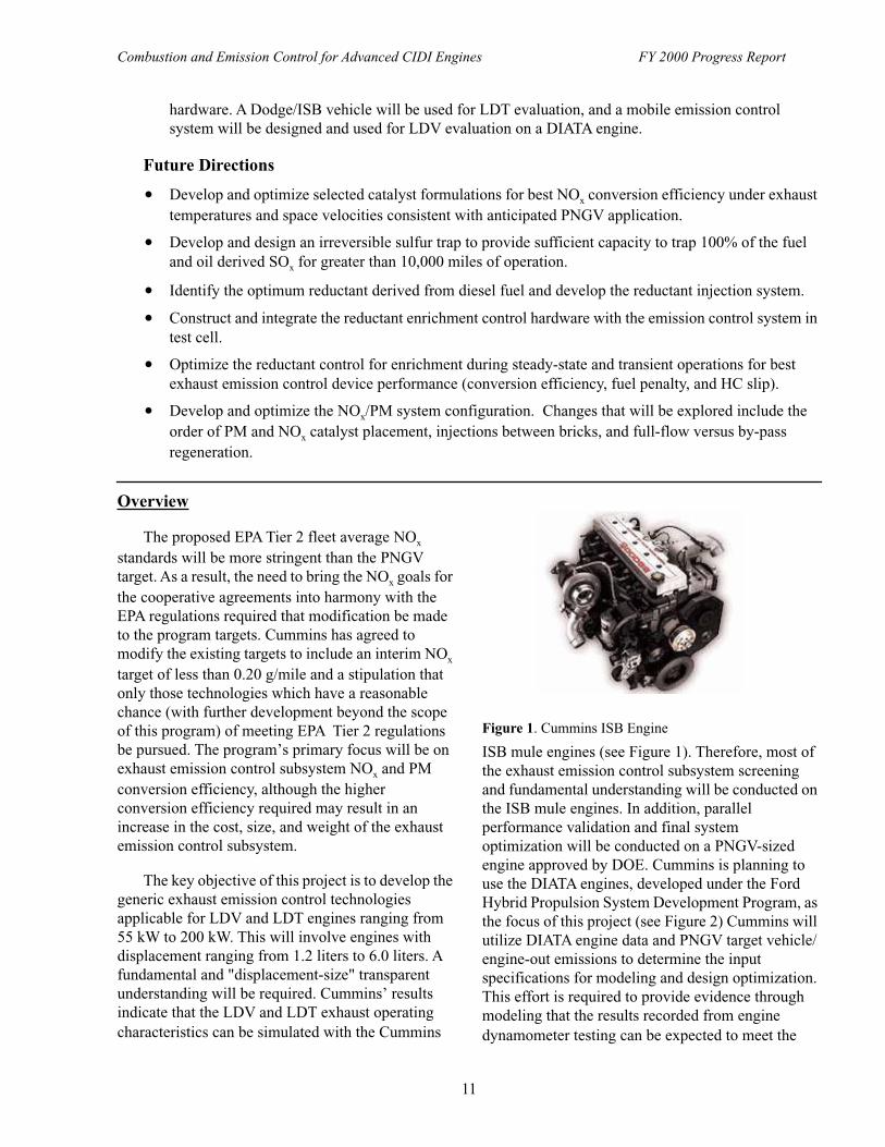
• Two DIATA engines have been received, and one has been assembled into a test skid that is near completion. The test skid will allow the relatively small DIATA engine to fit into Cummins’ test cells. The test skid, including DIATA engine, dynamometer, coupling, heat exchangers, and some electronic controls, will be able to be installed into a test cell with a minimum changeover time. Three low emission Cummins ISB breadboard engines have been procured and are being used extensively for emission control system model development and catalyst performance mapping.
• Among all the engine exhaust characteristics, exhaust temperature plays the most dominant role on exhaust emission control device performance. A correlation of engine-out NOx as a function of exhaust gas temperature for the FTP-75 cycle has been done to guide the exhaust emission control device development work.
• Progress has been made on identifying the best reductant for NOx adsorber catalysts. The results indicate that H2 is the best reductant, followed by a mixture of H2 and CO, followed by CO. Short straight chain (C4-C8) hydrocarbons are not good reductants.
• Significant effort is underway to develop and acquire the catalyst system and HC enrichment control hardware for system model validation and to conduct transient FTP-75 results on the prototype
Combustion and Emission Control for Advanced CIDI Engines FY 2000 Progress Report
11
hardware. A Dodge/ISB vehicle will be used for LDT evaluation, and a mobile emission control system will be designed and used for LDV evaluation on a DIATA engine.
Future Directions
• Develop and optimize selected catalyst formulations for best NOx conversion efficiency under exhaust temperatures and space velocities consistent with anticipated PNGV application.
• Develop and design an irreversible sulfur trap to provide sufficient capacity to trap 100% of the fuel and oil derived SOx for greater than 10,000 miles of operation.
• Identify the optimum reductant derived from diesel fuel and develop the reductant injection system.
• Construct and integrate the reductant enrichment control hardware with the emission control system in test cell.
• Optimize the reductant control for enrichment during steady-state and transient operations for best exhaust emission control device performance (conversion efficiency, fuel penalty, and HC slip).
• Develop and optimize the NOx/PM system configuration. Changes that will be explored include the order of PM and NOx catalyst placement, injections between bricks, and full-flow versus by-pass regeneration.
Overview
The proposed EPA Tier 2 fleet average NOx standards will be more stringent than the PNGV target. As a result, the need to bring the NOx goals for the cooperative agreements into harmony with the EPA regulations required that modification be made to the program targets. Cummins has agreed to modify the existing targets to include an interim NOx target of less than 0.20 g/mile and a stipulation that only those technologies which have a reasonable chance (with further development beyond the scope of this program) of meeting EPA Tier 2 regulations be pursued. The program’s primary focus will be on exhaust emission control subsystem NOx and PM conversion efficiency, although the higher conversion efficiency required may result in an increase in the cost, size, and weight of the exhaust emission control subsystem.
The key objective of this project is to develop the generic exhaust emission control technologies applicable for LDV and LDT engines ranging from 55 kW to 200 kW. This will involve engines with displacement ranging from 1.2 liters to 6.0 liters. A fundamental and "displacement-size" transparent understanding will be required. Cummins’ results indicate that the LDV and LDT exhaust operating characteristics can be simulated with the Cummins
ISB mule engines (see Figure 1). Therefore, most of the exhaust emission control subsystem screening and fundamental understanding will be conducted on the ISB mule engines. In addition, parallel performance validation and final system optimization will be conducted on a PNGV-sized engine approved by DOE. Cummins is planning to use the DIATA engines, developed under the Ford Hybrid Propulsion System Development Program, as the focus of this project (see Figure 2) Cummins will utilize DIATA engine data and PNGV target vehicle/engine-out emissions to determine the input specifications for modeling and design optimization. This effort is required to provide evidence through modeling that the results recorded from engine dynamometer testing can be expected to meet the
Figure 1. Cummins ISB Engine

Combustion and Emission Control for Advanced CIDI Engines FY 2000 Progress Report
12
vehicle emission requirements. Figure 3 is a detailed flow chart of the activities described above.
Approach
The targeted NOx reduction levels are difficult to achieve. Sulfur poisoning, thermal aging, catalyst masking, and hydrothermal aging are critical areas requiring investigation. In addition, effective use of reductants will be a key area of this investigation. NOx adsorber catalysts have shown the high NOx reduction levels using low-sulfur fuels under steady-state conditions. Effective regeneration during transient operation at low temperatures and NOx reduction without exceeding PM limits are critical hurdles. Plasma assisted catalytic reduction has also demonstrated high NOx reduction levels at low space velocities and temperatures similar to an automotive application. The principle of the non-thermal plasma for NOx control is to pass the exhaust gas through a reaction chamber where a rapid electrical pulse of short duration (25 kV, 28mHz, 10 nanosecond) is introduced. Plasma devices have two major attributes: the first is the ability to modify the NO2 to NO ratio and the second is the generation of active hydrocarbon-based species for NOx reduction. Major hurdles for this technology include electrical power management, complexity, safety, and catalyst effectiveness. With the combination of low-sulfur fuel, and the lower operating temperatures of the PNGV-type engines compared to heavy-duty diesel engines, investigation of higher platinum content
NOx reduction catalysts using the lean NOx approach also holds promise as a solution for NOx reduction.
The major milestones of the program are as follows:
• 7 months-results of performance model and preliminary exhaust emission control device subsystem hardware design.
• 15 months-test results on exhaust emission control prototype hardware and/or component tests and updated modeling results.
• 34 months-delivery of complete exhaust emission control subsystem suitable for evaluation with a 55 kW PNGV-type engine to ORNL.
Results
In Phase I of this project, the three NOx reduction technologies including plasma assisted catalytic NOx reduction, active lean NOx catalysis, and adsorber catalyst technology using intermittent rich conditions for NOx reduction were investigated in parallel in an attempt to select the best NOx control approach for PNGV exhaust emission control subsystem integration and development. These included critical lab/engine experiments, preliminary design and
Figure 2. Ford DIATA Engine
Figure 3. Flowchart of Project Activities

Combustion and Emission Control for Advanced CIDI Engines FY 2000 Progress Report
13
analysis, and ranking and selection of NOx control technologies against reliability, up-front cost, fuel economy, service interval/service hassle, and size/weight.
Figure 4 illustrates the NOx conversion efficiency of three different adsorber catalysts. These catalysts illustrate the potential for high NOx conversion over a fairly wide temperature range of catalyst inlet temperatures of 250oC to 400oC. However, in light-duty applications catalyst inlet temperatures are often below 250oC. An advantage of these catalysts is that they can use diesel fuel as a reductant. These catalysts need ultra-low sulfur content fuel - conversion efficiency was observed to deteriorate at the rate of 0.1% per hour using diesel fuel with 11 ppm sulfur content.
Control of PM emissions was demonstrated using a catalyzed soot filter (CSF). Figure 5 illustrates the capability of the CSF to reduce PM as a function of catalyst temperature. This device has the added advantages of providing reduction in HC and CO emissions, and being sulfur tolerant.
Conclusions
The results of preliminary exhaust emission control subsystem design and analysis indicated that the best NOx control approach for LDV and LDT applications is the NOx adsorber catalyst. NOx reduction efficiencies of 65 % and 87 % are required to achieve 0.20 g/mile and 0.07 g/mile NOx PNGV vehicle-out emissions, respectively. Both active lean NOx and PACR technology are not capable of
achieving the high conversion efficiency required for DOE/PNGV program objectives. The best NOx conversion efficiency achieved for active lean NOx and PACR was about 40 %. Some of the key findings are summarized below:
(A) Active Lean-NOx Catalyst
Positives
• Can use diesel fuel as reductant (diesel fuel can be added to the exhaust gases or done in-cylinder).
• A 40 % NOx conversion efficiency was demonstrated with diesel fuel as an injection reductant.
• Simple injection strategy with low complexity for implementation.
• Potential low cost solution for very clean diesel fuel (i.e., low-sulfur) with ultra-low engine-out emissions (less than 1.4 g/kW-hr NOx).
• Precious metal catalyst is only slightly inhibited by H2O.
Negatives
• High NOx conversion to N2O (about 50%-60% of the NOx reduced); N2O is a strong greenhouse gas.
• High sulfate formation rates at high temperatures for high-sulfur fuel. Not an issue with future low-sulfur fuel.
• Need combination of different catalysts to cover the whole exhaust temperature range for FTP-75 and US-06 cycles.
Figure 4. NOx Conversion Efficiencies for Three Different Adsorber Catalysts
Figure 5. PM Emission Control from Catalyzed Soot Filter

Combustion and Emission Control for Advanced CIDI Engines FY 2000 Progress Report
14
(B) Plasma Assisted Catalytic Reduction (PACR)
Positives
• Conversion of NO to NO2 at low temperatures, without SO2 to SO3 oxidation.
• Can enhance NOx conversion at low temperatures.
• Can use diesel fuel as a reductant.
• Simple reductant injection strategy similar to active lean NOx catalyst.
Negatives
• Additional power required for plasma generation.
• Very low space velocity/very large catalyst volume required for high conversion efficiency; a 40% NOx reduction was achieved with a 90 liter Gamma-Alumina catalyst.
• Potential safety issues due to high voltage/possible EMI generation.
• Benefit of non-thermal plasma decreased as the temperature is increased. No benefit was observed at temperatures greater than 280oC.
• Evidence of NOx adsorption as significant NOx consumption pathway. The catalyst would adsorb NOx at low temperatures (200-250oC) and would desorb NOx at higher temperatures (400-450oC).
(C) NOx Adsorber Catalyst
Positives
• Potential for high NOx conversion (>80%).
• Wide temperature range of peak operation (250oC to 400oC), yet not low enough for light-duty applications.
• Can use diesel fuel as a reductant.
• No infrastructure issues (as with urea distribution).
Negatives
• Rapidly poisoned by sulfur in the fuel and lube, and NOx conversion efficiency decreases at a rate of approximately 0.1 %
per hour with 11 ppm sulfur fuel; a sulfur trap will be required.
• Rich operation of injected hydrocarbon leading to high fuel penalty, HC slip, and SOF particulate production.
• Partial flow regeneration adds complexity but offers lower fuel economy penalty.
• High cost due to high precious metal catalyst loading.
• Complex reductant injection/control system.
List of Publications
1. Frank F. Mao and C.Z. Wan, "Fundamental of Sulfur Trap for Diesel Engine Emission Control," being prepared for Diesel Engine Emission Reduction Workshop, San Diego, CA, August 2000.
2. Matthew J. De Witt and C Z Wan, "Establishing Capabilities to Evaluate Reductants for NOx Adsorber Technologies," being prepared for Diesel Engine Emission Reduction Workshop, San Diego, CA, August 2000.
3. R. Mital, Shyan Huang, Bradlee Stroia, and C Z Wan, "Lean NOx Technology for Diesel Emission Control," being prepared for Diesel Engine Emission Reduction Workshop, San Diego, CA, August 2000.
List of Acronyms
CSF Catalyzed Soot FilterDIATA Direct Injection Aluminum
Through-Bolt AssemblyISB Integrated System B (a fully
electronic, 24-valve inline 6-cylinder B family engine)
LDV Light-Duty VehicleLDT Light-Duty TruckORNL Oak Ridge National LaboratoryPACR Plasma Assisted Catalytic ReductionPNGV Partnership for a New Generation of
VehiclesPM Particulate Matter

Combustion and Emission Control for Advanced CIDI Engines FY 2000 Progress Report
15
B. Application of Advanced Emission Control Sub-Systems to State-of-the-Art Diesel Engines
Houshun Zhang (primary contact), Brian BoltonDetroit Diesel Corporation (DDC)13400 West Outer Drive Detroit, MI 48239-4001(313) 592-9815, fax: (313) 592-7888, e-mail: [email protected]
DOE Program Manager: Kenneth Howden(202) 586-3631, fax: (202) 586-9811, e-mail: [email protected]
Contractor: Detroit Diesel Corporation, Detroit, MichiganDOE Cooperative Agreement No. DE-CE02-00EE5075Period of Performance: 7/1/99 through 12/31/01
Subcontractors: Engelhard Corporation; Michigan Technical University (MTU), Houghton, MI
This Project addresses the following OTT R&D Plan Barriers and Tasks:
Barriers
A. NOx Emissions
B. PM Emissions
Tasks
4. NOx Control Device R&D
5. Particulate Matter Control Device R&D
6. Prototype System Evaluations
Objectives
• Demonstrate technology for PNGV/Personal Transportation (PT) CIDI engine families of 0.5L/cylinder to ~0.7L/cylinder displacement, which will achieve DOE emissions targets for 2004 and 2007.
• Meet specific targets for engine-out emissions, efficiency, power density, noise, durability, production cost, and emission control sub-system volume and weight.
Approach
• Fundamentally pursue an integrated engine, emission control system and vehicle approach using a coupled experimental and analytical tool set.
• Develop comprehensive engine sub-system emission control models for emissions prediction.
• Integrate the sub-models into a global model for application over a wide range of time domains.
• Select and evaluate best (engine+emission control) system.
• Conduct system performance, emissions and durability evaluation testing.

Combustion and Emission Control for Advanced CIDI Engines FY 2000 Progress Report
16
Accomplishments
• Developed three-layer integrated engine+emission control virtual lab technical roadmap describing 0D, 1D and 3D paths and tool integration.
• Emission control, engine, vehicle and control system models described in the integrated roadmap are under development.
• SCR 3D transient CFD modeling is underway.
• Initial vehicle integrated SCR benchmark experimental testing is underway.
• Progress has been made on the PM model including 2D modifications and integration of new filtration and pressure drop elements.
• An engine setup is completed and engine-out emissions characterization is underway.
• Initiated catalyst aging tests.
Future Directions
• Complete initial version of three-layer integrated engine/emission control tool sets.
• Adapt combustion system for lowest possible engine-out emissions while simultaneously improving aftertreatment inlet temperature conditions for improved catalyst efficiency. Expand the synergistic engine+emission control coupling to include relevant emission-critical operating regions.
• Benchmark integrated engine+emission control system using best available technology to assess transient emission reduction potential and challenges.
Introduction
DDC is conducting the Low Emissions Aftertreatment and Diesel Emissions Reduction (LEADER) program under a DOE project titled: "Research and Development for Compression-Ignition Direct-Injection Engines (CIDI) and Emission Control Subsystem." LEADER is a 36-month program to develop emission control technologies on vehicles and demonstrate scalability for various vehicle inertia classes. DDC has significant experience in light-duty diesel engine development and has developed unique engines with displacements varying from 0.5L to 0.67L per cylinder for different applications. Figure 1 illustrates the scaling for advanced light-duty CIDI engines in personal transportation vehicle platforms.
Approach
The overall technical roadmap and approach are schematically summarized in Figure 2. The experimental transient FTP emission testing milestones shown will be supported by an integrated engine, emission control system, and vehicle
approach using a coupled experimental and analytical tool set. DDC and its subcontractors will develop a suite of advanced integrated catalyst and engine emission control models that predict quantitative emissions for a broad range of engine-out conditions and catalyst design specifications. These models will be integrated in a seamless fashion over a range of spatial resolutions. This tool will probe for the best combinations of emission control configurations and operating environments. Engine and vehicle test data will be used to validate
Figure 1. Personal Transportation Engine Technologies
Combustion and Emission Control for Advanced CIDI Engines FY 2000 Progress Report
17
the integrated models, thus providing further design recommendations and testing directions. Final selection and evaluation of the best engine+catalyst technology combinations will be tested in vehicles. A schematic of the development process is shown in Figure 3.
Results
4SDI peer review meetings were held that updated the program status and direction.
Engine tests were set up at DDC focusing on probing engine-out emissions reduction. This includes the combustion system, fuel injection system and EGR system.
Following a comprehensive literature search of emission control system data, analytical model development is underway. DDC is developing a methodology to integrate various catalyst models into a comprehensive engine+emission control system model, thereby addressing engine, vehicle
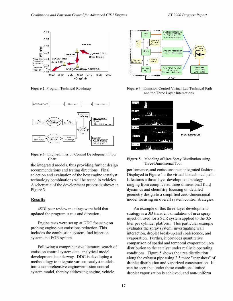
performance, and emissions in an integrated fashion. Displayed in Figure 4 is the virtual lab technical path. It features a three-layer development strategy ranging from complicated three-dimensional fluid dynamics and chemistry focusing on detailed geometry design to a simplified zero-dimensional model focusing on overall system control strategies.
An example of this three-layer development strategy is a 3D transient simulation of urea spray injection used for a SCR system applied to the 0.5 liter per cylinder platform. This particular example evaluates the spray system: investigating wall interaction, droplet break-up and coalescence, and evaporation. Further, it provides quantitative comparison of spatial and temporal evaporated urea distribution to the catalyst under realistic operating conditions. Figure 5 shows the urea distribution along the exhaust pipe using 2.5 msec "snapshots" of droplet distribution and vaporized concentration. It can be seen that under these conditions limited droplet vaporization is achieved, and non-uniform
Figure 2. Program Technical Roadmap
Figure 3. Engine/Emission Control Development Flow Chart
Figure 4. Emission Control Virtual Lab Technical Path and the Three Layer Interactions
Figure 5. Modeling of Urea Spray Distribution using Three-Dimensional Tool

Combustion and Emission Control for Advanced CIDI Engines FY 2000 Progress Report
18
urea delivery to the catalyst element is observed. This is an example of how the 3D version of the virtual lab tool will allow a compact, integrated vehicle solution with minimum compromise to system performance.
Michigan Technological University is progressing on the PM model development. The 2D model modifications were completed and the model was integrated with AGK’s filtration and pressure drop models. The integrated model has been validated against different filters. With this enhancement, the PM model accurately predicts the pressure drop in different PM filters. Figure 6 compares the predicted pressure drop with experimental data for a specified filter. The solid line is the simulation result and the dots represent the experimental data. Excellent correlation was observed. In particular, the ability to predict the initial transient loading behavior of the filter’s pressure drop was demonstrated. Additional activity at MTU includes updating the energy equation numerical algorithm and including species equations to model NO2 soot oxidation kinetics. A detailed experimental database has been established.
Conclusions and Future Directions
Detroit Diesel Corporation and its subcontractors are developing a comprehensive simulation suite for a high-fidelity simulation of the integrated CIDI engine-emission control systems for personal transportation light-duty vehicles. Preliminary sub-system models are being developed and exercised. An integrated (PM + NOx) baseline emission control
system will be tested on a vehicle chassis dynamometer using urea-based SCR as the NOx emission control technology, and a catalyzed DPF as the PM emission control technology. These catalyst technologies are the prime path for the program, although a NOx adsorber will also be studied as an alternative to SCR. The program technical approach was further verified with input from DDC, its subcontractors, and the 4SDI peer review team. Progress on the analytical models show good correlation with experimental results.
List of Acronyms
4SDI 4-Stroke Direct InjectionAGK A.G. KonstandopoulosBC Boundary ConditionCFD Computational Fluid DynamicsCIDI Compression-Ignition Direct-
Injection EnginesCRT Continuous Regeneration TrapDDC Detroit Diesel CorporationDOE Department of EnergyDPF Diesel Particulate FilterEGR Exhaust Gas RecirculationFTP Federal Test ProcedureHEV Hybrid Electric Vehicle EngineIC Initial ConditionFIE Fuel Injection EquipmentLEADER Low Emissions Aftertreatment and
Diesel Emissions ReductionMTU Michigan Technological UniversityNOx-ADS NOx AdsorberPM Particulate MatterPNGV Partnership for a New Generation of
VehiclePT Personal TransportationSCR Selective Catalytic ReductionSFTP Supplemental Federal Test
ProcedureVGT Variable Geometry Turbo
Figure 6. Comparison of the Predicted Pressure Drop by the Transient Filtration Model against the Experimental Data for a Filter

Combustion and Emission Control for Advanced CIDI Engines FY 2000 Progress Report
19
III. IN-CYLINDER COMBUSTION STUDIES, ADVANCED COMBUSTION RESEARCH, SENSORS, AND DIAGNOSTICS
A. Heavy-Duty Diesel Engine Combustion: Diffusion-Flame/Wall Interactions
John E. DecSandia National LaboratoriesP.O. Box 969, MS 9053Livermore, CA 94551-9699(925) 294-3269, fax: (925) 294-1004, e-mail: [email protected]
DOE Program Manager: Gurpreet Singh(202) 586-2333, fax (202) 586-1600; e-mail: [email protected]
Contractor: Sandia National Laboratories, Livermore, CAContract Number: DE-AC04-94AL85000
This Project addresses the following OTT R&D Plan Barriers and Tasks:
Barriers
A. NOx Emissions
B. PM Emissions
Tasks
3a. Identification of Advanced Combustion Systems
Objectives
• The overall objective of this project is to advance the understanding of diesel engine combustion and emissions formation through the application of advanced laser-based diagnostics.
• Specific objectives for FY 2000:
- Investigate diffusion-flame/wall interactions in a heavy-duty DI diesel engine and determine the potential of soot-deposition on the wall as a pathway to soot emissions.
- Perform complete relocation of the Heavy-Duty Diesel Engine Laboratory to CRF Phase II, and make numerous upgrades.
Approach
• Investigation of diffusion-flame/wall interactions:
- Develop an optical setup for imaging the leading edge of the combusting fuel jet as it impinges on the combustion-bowl wall in the Sandia/Cummins optically accessible engine.
- Obtain high-resolution OH PLIF (planar laser-induced fluorescence) images of the diffusion flame during wall interaction.
- Set up a dual-laser, dual-camera system to simultaneously image the OH-radical and soot distributions during jet/wall interaction to assess the likelihood for soot deposition.

Combustion and Emission Control for Advanced CIDI Engines FY 2000 Progress Report
20
Accomplishments
• Conducted a detailed investigation of the behavior of the reacting fuel jet as it encounters the combustion-bowl wall.
- Acquired simultaneous OH-PLIF and PLII-soot images showing that prior to contacting the wall, the soot is completely contained by an intact diffusion flame.
- Acquired images of the diffusion flame showing that the flame first remains active as the leading edge of the jet deforms and flattens along the wall surface, but that within 70 µs the flame is extinguished along the entire front of the jet that is against the wall.
- Showed that after the flame is extinguished by the wall, the soot-filled central region of the jet impinges directly on the wall surface, offering a potential pathway for soot emissions, i.e. wall deposition and eventual blow-off into the exhaust.
Future Directions
• Extend the jet/wall interaction study to include measurements of soot deposition rates to provide an estimate of the significance of this pathway to the total soot emissions.
• Establish an improved vertically oriented line-of-sight (LOS) extinction diagnostic to obtain a quantitative measurement of the total bulk-gas soot during the late-combustion soot burnout period.
- Obtain measurements over a range of operating conditions and compare results with previous engine-out and late-combustion PLII-soot image data.
• Use PLII to image the soot directly under the exhaust valve during blow-down and the exhaust stroke to determine the time-history of soot emissions from the cylinder.
- Correlate results with late-combustion LOS and PLII image data to help understand the contributions of the various pathways to soot emissions.
Introduction
Although laser diagnostics have improved our understanding of many aspects of diesel combustion, the interactions between the combusting fuel jet and the piston-bowl wall are not well understood. In heavy-duty engines these interactions occur with the combusting vapor-phase region of the jet, which consists of a central region containing soot and other products of rich-premixed combustion, surrounded by a diffusion flame [1]. If the diffusion flame is extinguished by the wall interaction, soot could be deposited on the wall and subsequently blown off, becoming an engine-out emission. Diffusion-flame quench at the wall would also reduce the burning rate and the rate of NOx formation as the flame surface area is reduced.
The objective of the current work is to investigate the behavior of the diffusion flame as it contacts the wall, and to determine whether jet/wall
interaction provides a means for soot to escape combustion and become an engine-out emission. This investigation, and all of the work on this project, are conducted in cooperation of our CRADA partners (Cummins, Caterpillar, and Detroit Diesel), and the results are presented at the cross-cut diesel CRADA meetings.
Approach
Laser-sheet imaging diagnostics provide a means to directly examine the behavior of the diffusion flame and soot distributions as the jet interacts with the wall. Since previous work has shown that the OH radical is a good marker of the diffusion flame during diesel combustion [2], planar laser-induced fluorescence (PLIF) imaging of OH was applied to the current investigation of the diffusion-flame/wall interaction. In addition, simultaneous OH PLIF and planar laser-induced incandescence (PLII) soot imaging was used to investigate the likelihood for
Combustion and Emission Control for Advanced CIDI Engines FY 2000 Progress Report
21
soot deposition on the bowl wall. The Sandia/Cummins optically accessible heavy-duty diesel engine was used to apply these diagnostics in a realistic diesel environment. Obtaining these images required developing a new optical setup with a quartz window in the piston bowl-rim, in-line with one of the cylinder-wall windows of the optical engine.
Prior to conducting this investigation of the jet/wall interaction, it was necessary to enhance the capability of the engine-support and other laboratory subsystems using up-to-date computerized-control and data-acquisition technology, as appropriate.
Results
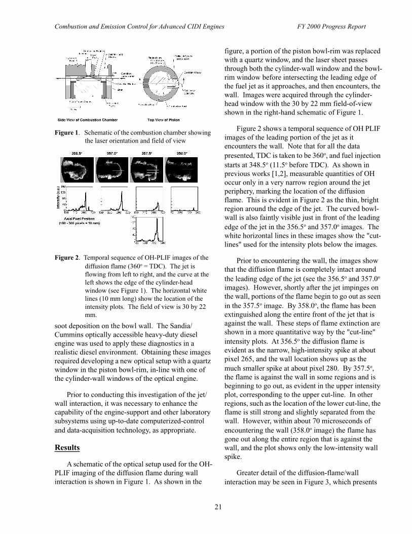
A schematic of the optical setup used for the OH-PLIF imaging of the diffusion flame during wall interaction is shown in Figure 1. As shown in the
figure, a portion of the piston bowl-rim was replaced with a quartz window, and the laser sheet passes through both the cylinder-wall window and the bowl-rim window before intersecting the leading edge of the fuel jet as it approaches, and then encounters, the wall. Images were acquired through the cylinder-head window with the 30 by 22 mm field-of-view shown in the right-hand schematic of Figure 1.
Figure 2 shows a temporal sequence of OH PLIF images of the leading portion of the jet as it encounters the wall. Note that for all the data presented, TDC is taken to be 360o, and fuel injection starts at 348.5o (11.5o before TDC). As shown in previous works [1,2], measurable quantities of OH occur only in a very narrow region around the jet periphery, marking the location of the diffusion flame. This is evident in Figure 2 as the thin, bright region around the edge of the jet. The curved bowl-wall is also faintly visible just in front of the leading edge of the jet in the 356.5o and 357.0o images. The white horizontal lines in these images show the "cut-lines" used for the intensity plots below the images.
Prior to encountering the wall, the images show that the diffusion flame is completely intact around the leading edge of the jet (see the 356.5o and 357.0o images). However, shortly after the jet impinges on the wall, portions of the flame begin to go out as seen in the 357.5o image. By 358.0o, the flame has been extinguished along the entire front of the jet that is against the wall. These steps of flame extinction are shown in a more quantitative way by the "cut-line" intensity plots. At 356.5o the diffusion flame is evident as the narrow, high-intensity spike at about pixel 265, and the wall location shows up as the much smaller spike at about pixel 280. By 357.5o, the flame is against the wall in some regions and is beginning to go out, as evident in the upper intensity plot, corresponding to the upper cut-line. In other regions, such as the location of the lower cut-line, the flame is still strong and slightly separated from the wall. However, within about 70 microseconds of encountering the wall (358.0o image) the flame has gone out along the entire region that is against the wall, and the plot shows only the low-intensity wall spike.
Greater detail of the diffusion-flame/wall interaction may be seen in Figure 3, which presents
Figure 1. Schematic of the combustion chamber showing the laser orientation and field of view
Figure 2. Temporal sequence of OH-PLIF images of the diffusion flame (360o = TDC). The jet is flowing from left to right, and the curve at the left shows the edge of the cylinder-head window (see Figure 1). The horizontal white lines (10 mm long) show the location of the intensity plots. The field of view is 30 by 22 mm.

Combustion and Emission Control for Advanced CIDI Engines FY 2000 Progress Report
22
images from different engine cycles, all taken at 357.5o. Due to small variations in injection timing and turbulence, jet penetration varies somewhat from cycle to cycle. The images in Figure 3 have been arranged in order of apparent penetration. These images show that as the jet encounters the wall, the leading edge deforms, flattening the diffusion flame along the wall surface. Despite being close to the wall, the flame remains active for a short time before being extinguished along the entire front of the jet that is against the wall.
The optical setup for the simultaneous OH-PLIF and PLII-soot images is shown in Figure 4. The beams of the 284 nm, ultra-violet laser (for OH PLIF) and the 532 nm doubled Nd:YAG-laser (for PLII-soot) are combined into overlapping laser sheets by a series of lens and a custom dichroic mirror. The two image types are captured on two separate intensified CCD cameras, with the signal being split between the two cameras by another dichroic mirror. The OH and soot images are then mapped with separate false color schemes before each image pair is combined into a single image using a special color table.
Figure 5 presents a temporal sequence of the combined, simultaneous OH and soot images. When printed in black and white, the soot region in the central part of the jet appears as dark gray, while the OH region around the jet periphery shows up as light gray. These images show that after the diffusion flame is extinguished at the wall surface, the soot
within the combusting jet impinges directly on the wall. This allows the soot to be deposited on the wall surface and escape combustion.
Conclusions
A detailed investigation of the jet/wall interaction in a heavy-duty diesel engine has been conducted using laser-sheet imaging. The data show that the diffusion flame at the jet periphery is extinguished by the wall, allowing the soot-filled central region of the jet to impinge directly on the wall surface. This provides a potential pathway for
Figure 3. A series of OH-PLIF images at 357.5o taken from different engine cycles. The curve at the left shows the edge of the cylinder-head window, and the bowl wall is shown by the white curve at the right in the first five images.
Figure 4. Optical setup for simultaneous OH-PLIF and PLII-soot imaging.
Figure 5. Temporal sequence of simultaneous OH and soot images. The curve at the left marks the edge of the window and the curve at the right marks the bowl wall.

Combustion and Emission Control for Advanced CIDI Engines FY 2000 Progress Report
23
soot emissions, i.e. wall deposition and eventual blow-off into the exhaust. The flame extinction at the bowl wall will also have an impact on combustion and NOx formation rates.
The results of this investigation improve our understanding of the mechanisms behinde a potentially significant, but largely unexplored, additional pathway to soot emissions. As engine manufacturers strive to produce engines with extremely low emissions, all potential mechanisms must be understood. This allows the manufacturers to develop correct engineering models and to better focus their development efforts on appropriate areas. In addition, the understanding of the effects of walls on reacting diesel fuel jets (and the associated impact on combustion, soot emissions, and NOx formation) provides information necessary for the development of more active predictive-numerical-models of diesel combustion.
Relocation of the Heavy-Duty Diesel Engine Laboratory has been completed, and the laboratory in now is fully operational in its new location.
List of References
1. Dec, J. E., "A Conceptual Model of DI Diesel Combustion based on Laser-Sheet Imaging," SAE Transactions, Vol. 106, Sec. 3, pp. 1319-1348, paper no. 970873, 1997.
2. Dec, J. E. and Coy, E. B. "OH Radical Imaging in a D.I. Diesel Engine and the Structure of the Early Diffusion Flame," SAE Transactions, Vol. 105, Sec. 3, pp. 1127-1148, paper no. 960831, 1996.
List of Publications/Presentations
1. Dec, J. E. and Kelly-Zion, P. L., "The Effects of Injection Timing and Diluent Addition on Late-Combustion Soot Burnout in a DI Diesel Engine based on Simultaneous 2-D Imaging of OH and Soot," SAE paper no. 2000-01-0238, presented at the SAE Congress, Mar. 2000.
2. Dec, J. E. and Kelly-Zion, P. L., "An Investigation of Late-Combustion Soot Burnout in a DI Diesel Engine using Simultaneous Planar Imaging of Soot and OH Radical," presented at
and published in the proceedings of the DEER Workshop, Castine, ME, July 1999.
3. Dec, J. E., Canaan, R. E., and Tree, D. R., "The Effect of Water-Emulsified Fuel on Diesel Soot Formation," presented at and published in the proceeding of the 219th American Chemical Society National Meeting, San Francisco, CA, Mar. 2000.
4. Dec, J. E., Diesel Combustion Progress Report, Cross-Cut Diesel CRADA Meeting, Oct. 1999.
5. Dec, J. E., Diesel Combustion Progress Report, Cross-Cut Diesel CRADA Meeting, Jan. 2000.
6. Dec, J. E., "A Conceptual Model of DI Diesel Combustion and its Relationship to Potential Investigations of Enhanced Autoignition," presented to the Ethyl Corporation, Mar. 2000.
7. Dec, J. E. and Tree, D. R., "Heavy-Duty Diesel Engine Combustion: Diffusion-Flame/Wall Interactions," DOE CIDI Combustion, Emission Control, and Fuels Review, May 2000.
8. Dec, J. E., "An Overview of Heavy-Duty Diesel Engine Research at Sandia," presented to a joint meeting of Ricardo North America and Universal Oil Products, May 2000.
9. Dec, J. E., "An Understanding of DI Diesel Combustion and Soot Burnout based on Laser-Sheet Imaging," presented to the Lubrizol Corporation, May 2000.
10. Dec, J. E. and Tree, D. R., "Diffusion-Flame/Wall Interactions in a Heavy-Duty DI Diesel Engine," Cross-Cut Diesel CRADA Meeting, May 31 - June 1, 2000.
List of Acronyms
CRADA Cooperative Research and Development Agreement
CRF Combustion Research FacilityDI Direct InjectionFY Fiscal YearLOS Line of SightPLIF Planar Laser-Induced FluorescencePLII Planar Laser-Induced IncandescenceTDC Top Dead Center

Combustion and Emission Control for Advanced CIDI Engines FY 2000 Progress Report
24
B. Development of a Combined Mass Flow Rate and Chemical Composition Sensor for the Intake of CIDI Engines Using Thin Film MEMS Sensors
Dr. Darby B. MakelMakel Engineering, Inc.1020 Marauder Street, Suite DChico, CA 95973(530)895-2771, fax: (530) 895-2777, e-mail: [email protected]
DOE Program Manager: Donna Lee Ho(202) 586-8000, fax: (202) 586-9811, e-mail: [email protected]
Contractor Makel Engineering, Inc., Chico, CaliforniaDOE Contract Number:DE-FC02-00EE50628; Period of Performance:4/1/00 to 3/31/00
Subcontractors: Case Western Reserve University, Cleveland, Ohio (Dr. C.C. Liu); University of Cal-ifornia, Berkeley, Berkeley, California (Dr. Robert Dibble)
This Project addresses the following OTT R&D Plan Barriers and Tasks:
Barriers
A. NOx Emissions
B. PM Emissions
Tasks
2. Sensors and Controls
Objectives
• Phase I:
- Design and fabricate a prototype sensor using MEMS technology.
- Perform laboratory feasibility tests.
- Perform application feasibility tests on a CIDI engine.
• Phase II:
- Design low cost integrated sensor module suitable for mass production.
- Perform detailed characterization testing to establish long-term accuracy, reliability, and life.
- Perform demonstration testing using test stand engine and on-road vehicles in conjunction with engine manufacturers.
Approach
• Phase I:
- Develop specifications for sensor operating requirements in consultation with industry partners.
- Modify existing designs of MEMS thin film chemical, pressure and flow sensors to meet sensor system requirements.

Combustion and Emission Control for Advanced CIDI Engines FY 2000 Progress Report
25
- Modify existing smart sensor control electronics to produce real-time data and linearization of analog signals that are proportional to mass flow rate, oxygen, hydrocarbon, and carbon dioxide concentrations.
- Fabricate and checkout two prototype sensors.
- Evaluate accuracy and time response for a practical sensor.
- Perform demonstration tests with a test stand mounted diesel engine.
Accomplishments
• Baseline set of sensor requirements developed to guide design of sensor.
• MEMS based device fabrication initiated.
Future Directions
• Integration of technology with engine control systems with engine OEMs.
• Demonstration of low cost production of sensor.
Introduction
The purpose of this project is to address the critical need for CIDI engine on-board sensor technology to enable emissions reductions and efficiency improvements. After one hundred years of combustion engine development, exact knowledge of the air/fuel ratio of the combustion in each cylinder on each cycle remains an elusive goal [1]. While there are numerous diagnostic measurement techniques such as optical absorption, light scattering and mass spectroscopy which are very powerful tools for engine development and laboratory testing, they are inherently too costly and complex to be practical engine sensors. MEMS (Micro-Electro-Mechanical Systems) technology holds the potential for addressing this need with a low cost solution that can be practical to implement in mass produced engines. Low cost MEMS-based pressure sensors are widely used in the automotive industry. The thin film MEMS sensors to be investigated in this program are fabricated by the same types of processes used for mass production of low cost integrated circuits.
Emissions reductions is a major challenge for CIDI engines. Electronic injection, exhaust gas recirculation (EGR), and cleaner fuels have all had an impact on reducing emissions. Further improvement in engine operation and reduction of emissions can be achieved by improved knowledge of the mass flow rate of air into the engine and
preferably each cylinder. Of particular interest is the calculation of instantaneous and cycle accumulated mass flow to each cylinder, as well as the concentration of oxygen, hydrocarbons, and carbon dioxide which may be present in engines using EGR to reduce emissions.
Approach
In Phase I, two integrated prototype units are being fabricated, and demonstration testing will be
Figure 1. Smart Engine Intake Sensor Uses Advanced Solid-State MEMS Sensors and Compact Micro-Electronics for Simultaneous Measurement of Oxygen Concentration, Hydrocarbons, and Real-Time Calculation of Instantaneous and Cycle Accumulated Mass Flow.

Combustion and Emission Control for Advanced CIDI Engines FY 2000 Progress Report
26
performed to define the capability of the system and sensors. The major components of the proposed Smart Engine Air Intake Sensor are shown in Figure 1. The system consists of two principal elements: (1) integrated micro-electronic sensor elements for gases of interest, velocity, pressure and temperature, and (2) miniature application specific integrated circuit (ASIC) based electronics to provide signal conditioning, signal processing, and communications functions. We envision this system to be integrated into a small (0.5" diameter x 2") package that would be suitable for integration into the intake manifold or at each intake valve on an engine. Phase II of the program will address the packaging and miniaturization issues in detail in Phase II of the program.
The first major task will be to select and adapt existing CWRU/MEI sensor designs for the oxygen, hydrocarbon, CO2, thermal flow, and pressure sensors. A set of system requirements will be developed through consultation with DOE and engine manufacturers. Sensor time response and sensitivity will be adjusted for expected detection ranges. These sensors will be used in die form (typically 3 mm x 3 mm and designed into a single integrated sensor head that can be mounted flush with a wall). The sensor control electronics will be adapted from existing designs for the prototype in Phase I and will be optimized in Phase II.
The second major task will be the fabrication and integration of the sensors and the electronics into two working prototypes. Firmware developed for the operation of the sensor system will be validated, and tests will be conducted to calibrate the sensors and to evaluate and compensate for cross sensitivities. Sensor stability, repeatability, and thermal cycle behavior will be tested.
The third major task will be to perform testing of the system using dynamometer mounted engines at U.C. Berkeley. Tests will be conducted using six-cylinder DI compression ignition engines capable of EGR and single cylinder test engines. The single cylinder engines will be configured for homogeneous charge combustion and with high levels of EGR. We will use the engine tests to validate bench-testing results and to develop a preliminary data package that we intend to share with engine manufacturers.
We plan to have one or more engine manufacturers participate in Phase II of the project.
Conclusions
A set of baseline requirements (Table 1) have been developed for the sensor which serve as the design requirements for the Phase 1. Application of these requirements to the known operational characteristics of the sensors under investigation indicated that the needed mass flow sensor can be achieved.
List of References
1. Sensor Needs and Requirements for Proton Exchange Membrane Fuel Cells Systems and Direct-Injection Engines, UCRL-ID-137767, Jan 2000.
List of Acronyms
ASIC Application Specific Integrated Circuit
CIDI Compression Ignition, Direct Injection
CWRU Case Western Reserve UniversityEGR Exhaust Gas RecirculationMEI Makel Engineering, Inc.MEMS Micro-Electro-Mechanical SystemsOEM Original Equipment ManufacturerUCB University of California, Berkeley
Parameter Specification
Oxygen Range 25 ppm-25% @ STP
Hydrocarbon Range 50 ppm -1% @ STP
Carbon Dioxide 50 ppm to 10% @ STP
Temperature -40oC to 125oC
Pressure 10 to 25 psia
Velocity 0 to 20 m/sec
Sensor Response Time Less than 100 microseconds
Operating Pressure 1.5 atm to 1 torr
Sensor Head Size 1.5 cm diameter, flush mount
Power Consumption < 3 watts per sensor module
Power to Sensor 12 or 24 VDC, 300 mA max
Data Communications Digital Protocol/analog output
Table 1. Preliminary Specifications for the Smart Engine Air Intake Sensor

Combustion and Emission Control for Advanced CIDI Engines FY 2000 Progress Report
27
C. Advanced CIDI Engine Diesel Combustion R&D
Paul MilesSandia National LaboratoriesP.O. Box 969, MS9053Livermore, CA 94551(925) 294-1512, fax: (925) 294-1004, e-mail: [email protected]
DOE Program Manager: Kathi Epping(202) 586-7425, fax (202) 586-9811, e-mail: [email protected]
Contractor: Sandia National Laboratories, Livermore, CAContract Number DE-AC04-94AL85000
Subcontractors: University of Wisconsin Engine Research Center (UW ERC), Madison, WI; Wayne State University (WSU), Detroit, MI
This Project addresses the following OTT R&D Plan Barriers and Tasks:
Barriers
A. NOx Emissions
B. PM Emissions
Tasks
3. Fundamental Combustion R&D
Objective
• To provide the physical understanding of in-cylinder combustion processes needed to meet the efficiency and emissions standards of the PNGV vehicle.
Approach
• Obtain measurements which clarify the fundamental in-cylinder physical processes important to CIDI diesel combustion through use of optical diagnostic techniques in a geometrically-realistic optical engine.
• Correlate in-cylinder processes observed in the optical engine to tailpipe emissions and traditional, pressure-based performance analysis in a conventional single-cylinder test engine with geometry and operating conditions as close as possible to the optical engine (WSU).
• Incorporate fundamental physical processes into detailed computer models of engine combustion; validate the output of these models against traditional test engine emissions and performance (UW-ERC).
Accomplishments
• Investigated the influence of flow swirl on rate of heat release and spatial combustion characteristics, employing analysis of cylinder pressure data and imaging of natural luminosity. Established:
- The decrease of ignition delay with increasing swirl, with corresponding decreases in peak heat release and combustion noise.
- The invariance of ignition locations with flow swirl.

Combustion and Emission Control for Advanced CIDI Engines FY 2000 Progress Report
28
- The increased rates of mixing-controlled combustion achieved with higher swirl.
- The greater squish volume combustion activity which occurs with higher swirl.
- The zones of late cycle-oxidation of soot and unburned hydrocarbons (UHC), including unexpected asymmetries.
• Investigated the combustion of cetane-degraded fuels (ethanol/D2) blends on the combustion process. Established:
- The invariance of ignition location with ignition delay (cetane number).
- The role of combustion gas expansion during the premixed burn in enhancing turbulence and rates of heat release in the mixing-limited combustion.
• Investigated the effects of injector nozzle type and opening pressure on the combustion process. Established:
- The minor influence of nozzle style (VCO vs. minisac) on combustion phasing and spatial characteristics.
- The dependency of ignition location and squish volume combustion activity on nozzle opening pressure.
• Improved data acquisition capability and experimental controls, and installed laser systems required for future work.
• Completed characterization of combustion performance at three key speed/load conditions and comparison with optical engine (WSU).
• Conducted tests of emissions (smoke, NOx, UHC, CO) and ISFC at three key speed/load conditions, for several EGR levels and fuel injection pressures (WSU). Compared engine emissions and performance with state-of-the-art 4-valve CIDI engines.
• Enhanced traditional engine laboratory capabilities, adding PM mass and noise measurement capability (WSU).
• Performed full-cycle simulations for both traditional and optical engines at three key points, Rs=1.5 (UW ERC). Compared pressure-derived results with experimental data.
• Performed full-cycle simulations at 2000 rpm/5.0 bar IMEP load point for variable swirl ratios. Compared and contrasted computed and experimental results. Established:
- The "bluff-body" like character of the fuel sprays, and the importance of recirculation zones in establishing the ignition location.
- The increased fuel in the squish volume at higher swirl ratios, corresponding to the experimentally observed increased combustion activity.
- The role of the velocity field set-up by the swirl/squish interaction in positioning the fuel near the entrance to the squish volume and the role of the gas expansion in forcing the unburned fuel into the squish volume.
- The need for further code development/refinement to accurately predict the locations of late-cycle soot oxidation.
• Identified the inability of traditional (shell) ignition sub-models to accurately predict ignition delay and location under idle conditions in the CIDI engine. Developed and commenced testing of new model valid for high EGR levels.
• Continued development and verification of computationally efficient spray models.

Combustion and Emission Control for Advanced CIDI Engines FY 2000 Progress Report
29
Future Directions
• Provide more detailed, quantitative data to clarify the effects of the in-cylinder velocity field (including turbulence levels) on the fuel distribution, mixing rates, and late-cycle burnout. Continue with application of laser-based techniques to investigate the influence of swirl on the spatial distributions of particulate and of liquid phase fuel. Compare results on a detailed level with model predictions.
• Optimize combustion system through continued traditional engine testing. Investigate ability of codes to predict the trends of the emissions and performance testing as the optimization proceeds. Commence with development of a comprehensive data base detailing the trade-offs in emissions and performance as injection pressure, swirl level, and EGR are varied.
• Perform computer simulations to compare with traditional test engine emissions results and in-cylinder measurements. Further refine and test computational sub-models for ignition and sprays
Introduction
CIDI engines intended for passenger car or light-duty truck applications differ from heavy-duty diesel engines in two important aspects. First, they feature swirl-supported combustion systems. In-cylinder flow swirl influences the entire combustion process-from the initial preparation of a combustible mixture to the final burnout of the soot and unburned hydrocarbons. Second, the interaction of the combustion chamber walls with the in-cylinder flows, sprays, and combustion becomes an important factor in determining the evolution of the combustion process. To develop fuel efficient engines in this size class, a sound understanding of the physics of the swirl-supported combustion and of the wall interactions is required. Moreover, computational models must capture the relevant physical processes if they are to produce accurate results and serve as reliable design tools.
Approach
In this research project, a three-pronged approach is taken toward obtaining the required physical understanding and reliable modeling capabilities: detailed measurements of the flow and combustion processes are made in an optically-accessible laboratory test engine; emissions, performance and fuel consumption measurements are made in a traditional single-cylinder test engine; and computer simulations are performed and compared to the data obtained in the optical and traditional test engines. Natural synergies emerge among these three areas. For example, the
comparison of the computed and the experimental results serves to establish the validity of the various sub-models in the codes, to verify the ability of the codes to accurately predict global parameters such as emissions, and to assist in the interpretation of the experimental data. Similarly, traditional test engine measurements serve to identify interesting operating parameter trade-offs that bear further investigation either numerically or experimentally in the optical engine.
Results
The optically-accessible CIDI diesel engine facility is depicted in Figure 1. This facility employs a slotted, extended piston assembly with a quartz combustion chamber that permits the progress of combustion to be visualized from below. In addition,
Figure 1. Schematic view of the optical engine facility

Combustion and Emission Control for Advanced CIDI Engines FY 2000 Progress Report
30
the upper region of the cylinder liner is equipped with quartz windows that allow a lateral view of the combustion process to be obtained. This lateral view capability, in a configuration that maintains the faithful combustion chamber geometry, is a unique aspect of this facility. The engine bowl geometry, bore, and stroke are typical of state-of-the-art CIDI diesel engines for passenger car applications. Variable cylinder swirl levels can be achieved through throttling of one of the intake ports. The achievable swirl levels span the range employed by most DI diesel engines.
Analysis of pressure data and of images of natural combustion luminosity in the optical engine has been employed to study the effect of swirl on various aspects of the combustion process. Figure 2 presents the effect of variable swirl on the apparent heat release rate. Note that increasing swirl can be seen to decrease the ignition delay, leading to lower peak heat release rates and consequently quieter operation. Images of early combustion chemiluminescence demonstrate that the ignition location remains the same for all three swirl ratios, as can be seen in Figure 3. Furthermore, computed ignition locations (also shown in Figure 3) can be seen to agree well with the measured locations. A
more detailed examination of the computed velocity field has demonstrated that this invariance in ignition location is associated with flow recirculation and re-entrainment zones behind the fuel spray.
As combustion progresses beyond the premixed burning period, a period of mixing-controlled combustion is entered in which little difference is seen in the heat release rate with swirl ratio. During this time, the mixing is likely dominated by the turbulence generated by the fuel injection process. As combustion proceeds, however, a clear increase in
Figure 2. The effect of swirl on the apparent heat release rate. The envelope of repeatability of the data is illustrated for a swirl ratio Rs of 2.5, which appears as a heavy line in Figure 2. Note that the differences observed with variable swirl are generally greater than the repeatability of the data.
Figure 3. A comparison of the experimental and the computed ignition locations for the three swirl ratios.
Figure 4. Images of luminosity obtained during the latter portion of the mixing-controlled combustion period.

Combustion and Emission Control for Advanced CIDI Engines FY 2000 Progress Report
31
the rate of heat release with increased swirl ratio can be seen between about 7 and 16 crank angle degrees, during the latter part of the mixing controlled burn (see Figure 2). Images of combustion luminosity during this time period are shown in Figure 4. The notable differences in the spatial distribution of combustion luminosity are an increase of activity in the squish volume at the higher swirl ratios and a decrease in activity in the upper, central region of the bowl. Comparison with computed results indicates that the increased squish volume activity is due to the presence of a greater amount of fuel within the squish volume at higher Rs, as is illustrated in Figure 5. Fuel in the squish volume is undesirable, because heat losses in the squish volume may cause the flame to quench, leading to particulate and UHC emissions. More fuel enters the squish volume at higher swirl ratios due to differences in the mean velocity field caused by the swirl/squish interaction, as revealed by the computational results. Computations also indicate that the decreased activity in the upper central bowl regions is likely due to increased turbulence at higher swirl levels, leading to a more rapid burnout of fuel in those regions and less activity at the time shown in Figures 4 and 5.
Figure 6 presents the soot-NOx trade-off for several EGR rates and injection pressures at the 2000 rpm, 5.0 bar IMEP load point. The behavior seen is
typical of state-of-the-art CIDI engines, and shows the turn-up in particulate matter at about 5 gm NOx/kg fuel that is considered the current lower bound of NOx emissions for CIDI engines. The smoke numbers seen here, of between 1 and 3 Bosch Smoke Units (BSU), are somewhat high, as best-in-class engines will typically exhibit smoke levels of about 0.5 BSU at these NOx levels and an 800 bar injection pressure. The higher than expected smoke numbers are within the range of expected improvements as the details of the combustion system are optimized, and the ability of the computed results to follow the optimization process will provide a rigorous test of the current and future CIDI engine models.
Conclusions
Imaging of combustion luminosity and heat release analysis, combined with computational model predictions, has led to considerable insight into the effect of swirl on the combustion process in a CIDI engine typical of engines intended for passenger car applications. Swirl is found to decrease ignition delay as well as the peak rates of heat release, although the spatial character of the ignition process is not changed. In addition, increased swirl is found to increase the rate of combustion during the latter part of the mixing controlled burn, and to increased squish volume activity. Computations assist in determining the underlying cause behind these observations.
Figure 5. Computed fuel distributions, showing the increased fuel found in the squish volume at the higher swirl ratios.
Figure 6. The soot-NOx trade-off determined in the traditional test engine, for fixed location of peak pressure as EGR and injection pressure are varied.
Combustion and Emission Control for Advanced CIDI Engines FY 2000 Progress Report
32
Testing in a traditional test engine has demonstrated that the test engine geometry is capable of achieving best-in-class emission performance with additional combustion system optimization. Performing this optimization provides an opportunity to test the ability of the computational models to accurately predict trends in CIDI engine performance and emissions.
List of Publications
1. Miles, P.C. "The Influence of Swirl on HSDI Diesel Combustion at Moderate Speed and Load," Spring SAE Fuels and Lubricants Meeting, 19-20 June 2000; SAE Paper No. 2000-01-1829.
2. Miles, P.C. " Combustion of an Ethanol/Diesel Fuel Blend in an HSDI Diesel Engine," To be presented at THIESEL 2000, Thermofluidynamic processes in Diesel Engines, 13-15 Sept. 2000.
3. Han, J.S., Wang, T.C., Lai, M.-C., Henein, N.A., Miles, P.C. and Harrington, D.L. "Dynamics of Multiple Injection Fuel Sprays in a Small-Bore HSDI Diesel Engine," SAE Int’l. Congress, 6-9 March 2000; SAE Paper No. 2000-01-1253.
4. Henein, N.A., Lai, M.-C., Wang, T.C., and Miles, P.C. "Combustion and Emission Characteristics of a Single-Cylinder HSDI Diesel Engine," Spring Technical Conference of the Central States Combustion Institute, 16-18 April 2000.
5. Tennison, P.J. and Reitz, R.D. "The Effects of Common Rail Injection Parameters on Emissions and Performance of a HSDI Diesel Engine," ASME Fall IC Engines Conference, 16-20 Oct. 2000.
6. Bianchi, G.M., Michelassi, V., and Reitz, R.D. "Modeling the Isotropic Dissipation in Engine Flows by Using the Linear k-ε Model," ASME Fall IC Engines Conference, 16-20 Oct. 2000.
7. Kong, S.-C., Senecal, P.K., and Reitz, R.D. "Developments in Spray Modeling in Diesel and Direct-Injection Gasoline Engines," Oil & Gas Science and Technology - Rev. de l’IFP, Vol. 54, No. 2, pp. 197-204, 1999.
List of Presentations
1. Miles, P.C. "Combustion Performance and Natural Luminosity at Key Point III: Effect of Varying Swirl"; Richards, K. "Motoring and Combustion Simulation of the Optical and Metal HSDI Engines"; Henein, N.A. and Lai, M.-C. "CIDI Metal Engine Instrumentation and Testing"; Diesel Combustion CRADA Meeting, 12-13 Oct. 1999, USCAR, Southfield, MI.
2. Miles, P.C. "Combustion Performance and Chemiluminescence Imaging: A Comparison of Neat D2 with an Ethanol/D2 Blend"; Henein, N.A. "Effect of Injection Pressure on the Trade-Offs in the Metal CIDI"; Richards, K. "Progress on HSDI Diesel Engine Modeling and Assessment of Spray Models"; Diesel Combustion CRADA Meeting, 20-21 Jan. 2000, Sandia Natl. Labs., Livermore, CA.
3. Richards, K. "Progress on HSDI Diesel Engine Modeling and Assessment of Spray Models"; Henein, N.A. "Effect of Injection Pressure, EGR and Swirl on the Emissions in the CIDI Metal Engine"; Paul Miles, P.C. "Progress and Current Status in the HSDI Combustion Partnership"; Diesel Combustion CRADA Meeting, 31 May - 1 June 2000, USCAR, Southfield, MI.
4. Miles, P.C., Henein, N.A., Lai, M.-C., Reitz, R.D., and Richards, K. "CIDI Diesel Combustion: Progress June 1999 - Present," DOE OATT Annual Review, 22-24 May, Argonne Natl. Lab., Argonne, IL.
List of Acronyms
BSU Bosch Smoke UnitCAD Crank Angle DegreeCIDI Compression Ignition Direct
InjectionD2 Number 2 Diesel FuelDI Direct InjectionEGR Exhaust Gas RecirculationHSDI High-Speed Direct-InjectionIMEP Indicated Mean Effective PressureISFC Indicated Specific Fuel
ConsumptionPNGV Partnership for a New Generation
VehicleTDC Top Dead CenterUHC Unburned Hydrocarbon

Combustion and Emission Control for Advanced CIDI Engines FY 2000 Progress Report
33
UW-ERC University of Wisconsin Engine Research Center
VCO Valve Covered OrificeWSU Wayne State University

Combustion and Emission Control for Advanced CIDI Engines FY 2000 Progress Report
34
D. Extending Exhaust Gas Recirculation Limits in CIDI Engines
Johney Green, Jr. (primary contact) and Stuart DawOak Ridge National LaboratoryP.O. Box 2009Oak Ridge, TN 37831-8088(423) 574-0373, fax (423) 574-2102, e-mail: [email protected]
DOE Program Manager: Kathi Epping(202) 586-7425, fax (202) 586-9811, e-mail: [email protected]
ORNL Technical Advisor: Ralph McGill(423) 574-4077, fax (423) 574-2102, e-mail: [email protected]
CRADA Partner: Ford Motor Company, Dearborn, MichiganCRADA No. ORNL 95-0337Ford Investigators: John Hoard (primary contact), Lee Feldkamp, Tony Davis, and Frank Connolly(313) 594-1316, fax: (313) 594-2923, e-mail: [email protected]
This Project addresses the following OTT R&D Plan Barriers and Tasks:
Barriers
A. NOx Emissions
Tasks
2. Sensors and Controls
4e. R&D on NOx Reducing Technologies
Objective
• Develop options for extending the practical EGR limit to further reduce engine-out NOx from CIDI engines.
Approach
• Identify correlations between EGR operating and system parameters and combustion emissions.
• Evaluate correlations between existing engine sensors and pressure/emissions signals to develop a virtual HC/PM/NOx sensor concept.
• Develop a low-order dynamic model that captures the relationship between EGR, combustion, and emissions.
• Exploit information from the virtual sensor and low-order model to develop a dynamic EGR control concept.
Accomplishments
• Conducted EGR experiments on the 1.2-L, 4-cylinder Ford DIATA (Direct Injection, Aluminum, Through-bolt Assembly) diesel engine.
• Conducted EGR experiments at ORNL with a 1.9-L, 4-cylinder VW TDI engine outfitted with a LBNL diesel particulate scatterometer to measure PM density, a Cambustion fast-FID analyzer to measure cycle-resolved HC emissions, a Tapered Element Oscillating Microbalance (TEOM) to

Combustion and Emission Control for Advanced CIDI Engines FY 2000 Progress Report
35
measure PM mass, a Scanning Mobility Particle Sizer (SMPS) to measure PM size, and Kistler in-cylinder pressure transducers to obtain combustion parameters.
• Discovered correlations between emissions and combustion parameters using data from VW TDI engine.
• Observed similar correlations in emissions and combustion data from Ford DIATA engine.
• Developed concept for a virtual sensor and control strategy that can be used to extend EGR limits in CIDI engines.
Future Directions
• Demonstrate proof-of-principle for virtual emissions sensor by correlating in-cylinder pressure measurements with PM, HC, and NOx emissions at high EGR on multiple CIDI engines.
• Demonstrate feasibility of virtual sensors by developing correlation between existing sensors (e.g., crankshaft acceleration) and in-cylinder pressure measurements.
• Demonstrate usefulness of a low-order dynamic model for predicting the relationship between EGR, combustion, and emissions.
• Demonstrate active feedback control for stabilizing engine operation at high EGR, thereby reducing NOx by as much as 50%.
Introduction
This activity builds on an earlier collaboration between ORNL and Ford under a pre-existing CRADA (ORNL 95-0337). Under the original CRADA, the principal objective was to understand the fundamental causes of combustion instability in spark-ignition engines operating at lean air-fuel ratios. The results of this earlier activity demonstrated that such combustion instabilities are dominated by the effects of residual gas remaining in each cylinder from one cycle to the next. A very simple, low-order model was developed that explained the observed combustion instability as a noisy nonlinear dynamical process. The model concept led to development of a real-time control strategy that could be employed to significantly reduce cyclic variations in real engines using existing sensors and engine control systems. Figure 1 illustrates the effectiveness of this control in a commercial engine.
With funding from OAAT, the CRADA has been modified to focus more on EGR and CIDI engines. The modified CRADA now includes engine experiments and analysis at both Ford and ORNL.
Activities at Ford
The strong correlation between hydrocarbon (HC) emissions and location of peak cylinder pressure in the DIATA engine is illustrated in Figure 2. We observe that HC emissions correlate with EGR rate, and these in turn correlate with the combustion process (as reflected in the location of
Figure 1. Experimental example of reduced cylinder-to-cylinder combustion instability achieved on commercial spark-ignition engine with cycle-resolved feedback control. Deviations from dashed line in upper figures and peaks in lower figures reflect high instability.

Combustion and Emission Control for Advanced CIDI Engines FY 2000 Progress Report
36
the peak cylinder pressure or LPP). Note that at higher EGR levels, very small changes in EGR rate have a highly nonlinear effect.
Activities at ORNL
ORNL experiments with the 1.9-L VW TDI engine were conducted in November of 1999. The purpose of these experiments was to confirm and extend the correlations observed in the Ford DIATA experiments. The VW engine was equipped to measure cycle-resolved PM density, cycle-resolved HC emissions, time-averaged HC, NOx and CO emissions, PM mass, PM size, and cylinder pressure from multiple cylinders.
Figure 3 shows the nonlinear behavior of HC and PM emissions at high EGR levels. If the engine could be operated at an EGR rate of 40% instead of 25%, there would be a 60% reduction in NOx emissions. The correlation between PM particle size and EGR rate is shown in Figure 4. The number of larger particles increases while the number of smaller particles decreases at high EGR rates. Cycle-resolved particulate density measurements reveal a different level of PM generation for each cylinder (Figure 5). The cylinder-to-cylinder variability most likely results from the mal-distribution of EGR to the cylinders. Figure 6 shows that HC emissions increase in cycle-to-cycle variability as EGR rate increases.
We believe that the mechanism behind the cycle-to-cycle variations in HC emissions is also responsible for the cylinder-to-cylinder communication depicted in Figure 7. A similar
Figure 2. Example correlation between combustion and emissions for the DIATA engine with increasing levels of EGR. Combustion delay is characterized by shifts in location of the peak cylinder pressure. Note similar trends for HC emissions and combustion delay with EGR.
Figure 3. Sharp transition in HC and PM emissions for VW engines as EGR is increased. The solid arrows indicate typical existing operating limits set to prevent occasional excursions into high HC and PM. The dotted arrows indicate potential operating points if the engine can be stabilized by high-speed feedback control, allowing substantial NOx reduction with only slight HC and PM increases.
Figure 4. Example correlation between particle size and EGR rate. It appears that EGR particles reintroduced into the combustion chamber act as nuclei for new particles and agglomerate to form larger particles.

Combustion and Emission Control for Advanced CIDI Engines FY 2000 Progress Report
37
synchronization between cylinder pairs was also observed and eliminated in the Ford spark-ignition engine control experiments (Figure 1). The correlations between emissions and EGR rate shown in Figures 2 and 8 lead us to believe that relationship can be exploited and used to develop a virtual sensor. The sensor would utilize existing engine sensors (e.g., crankshaft acceleration) and relate them to emissions at a given EGR rate. A low-order model would also be developed to gain a better understanding of the mechanism behind these correlations. The information obtained from these
tools would serve as the basis for advanced dynamic EGR control.
Summary
Experimental work during FY2000 focused on the development of high-time-resolution measurements of particulate matter, hydrocarbons, and nitrogen oxides. These emissions monitoring capabilities have significantly improved our ability to resolve the impact of cylinder-to-cylinder imbalances, EGR mal-distribution, and cycle-to-cycle combustion variations on the transient emissions spikes associated with high EGR rates. Recent experimental results have revealed a possible mechanism for the growth of PM particle size at high EGR rates and strong correlations between in-cylinder pressure measurements and time-average PM/HC/NOx emissions. The experimental results also indicate that diesel combustion instability patterns reflect cylinder-to-cylinder interactions that have features similar to those in spark-ignited engines at high EGR, although the combustion details are significantly different. These results
Figure 5. Example cycle-resolved PM density measurement. Cylinder-to-cylinder differences in PM generation are clearly visible.
Figure 6. The cycle-to-cycle variability of HC emissions increases as EGR rate increases.
Figure 7. Synchronization (cross-talk) between cylinders F-0 and F-1 in the VW engine is similar to the synchronization observed in the uncontrolled spark-ignition engine experiment (Figure 1). Such interaction contribute to high EGR instability.

Combustion and Emission Control for Advanced CIDI Engines FY 2000 Progress Report
38
continue to confirm the importance of experimental characterization and modeling of EGR and fueling systems for developing strategies to maximize NOx reduction potential.
The objectives in FY2001 are to demonstrate a virtual sensor concept for predicting HC, PM, and NOx emissions and to demonstrate a low-order dynamic EGR/emissions model for predicting and controlling combustion instabilities near the EGR limit. The virtual sensor approach is based upon exploiting the relationships between existing vehicle sensor outputs and emissions. The low-order dynamic EGR/emissions model will exploit the relationship between combustion instability, emissions, and the propagation of combustion instability effects through the engine/EGR system. This model is expected to serve as the basis for demonstrating advanced dynamic EGR control.
List of Publications
1. Daw C.S., Kennel M.B., Finney C.E.A., Connolly F.T. (1998). "Observing and modeling
nonlinear dynamics in an internal combustion engine", Physical Review E 57:3, 2811-2819.
2. Daw C.S., Green J.B. Jr., Wagner R.M., Finney C.E.A., Connolly F.T. (2000). Synchronization of combustion variations in a multi-cylinder spark ignition engine. Twenty-Eighth International Combustion Symposium (Edinburgh SCOTLAND; 2000 July 30 - August 04).
3. Finney C.E.A., Green J.B. Jr., Daw C.S. (1998). "Symbolic time-series analysis of engine combustion measurements", SAE Paper No. 980624.
4. Green J.B. Jr., Daw C.S., Armfield J.S., Finney C.E.A., Wagner R.M., Drallmeier J.A., Kennel M.B., Durbetaki P. (1999). "Time irreversibility and comparison of cyclic-variability models", SAE Paper No. 1999-01-0221.
5. Wagner R.M., Drallmeier J.A., Daw C.S. (1998). "Nonlinear cycle dynamics in lean spark ignition combustion", 27th International Symposium on Combustion (Boulder, Colorado USA; 1998 August 2-7).
6. Wagner R.M., Drallmeier J.A., Daw C.S. (1998). "Prior-cycle effects in lean spark ignition combustion: fuel/air charge considerations", SAE Paper No. 981047.
7. Wagner R.M., Green J.B. Jr., Storey J.M., Daw C.S. (2000). Extending exhaust gas recirculation limits in diesel engines. 2000 Annual Conference and Exposition of the Air & Waste Management Association (Salt Lake City, Utah USA; 2000 June 18 - 22), Paper 643.
List of Acronyms
CIDI Compression-ignition direct injection
CRADA Cooperative Research and Development Agreement
DIATA Direct Injection, Aluminum, Through-bolt Assembly
EGR Exhaust Gas RecirculationHC HydrocarbonsLBNL Lawrence Berkeley National
LaboratoryLPP Location of Peak PressureNOx Oxides of Nitrogen
Figure 8. VW experiments reveal the same correlation observed in DIATA experiments (Figure 2) between peak pressure location and emissions. The correlations between combustion measurements (e.g. crankshaft acceleration) and emissions will be employed to develop a virtual sensor concept.

Combustion and Emission Control for Advanced CIDI Engines FY 2000 Progress Report
39
OAAT Office of Advanced Automotive Technologies (U.S. Department of Energy)
PM Particulate MatterSMPS Scanning Mobility Particle SizerTDI Turbocharged Direct InjectionTEOM Tapered Element Oscillating
MicrobalanceVW Volkswagen

Combustion and Emission Control for Advanced CIDI Engines FY 2000 Progress Report
40
E. Measuring the Cylinder-to-Cylinder Distribution of Recirculated Exhaust Gas during Transient Operation of a CIDI Engine
R. M. GreenSandia National Laboratories7011 East Avenue, MS 9053Livermore, CA 94550(925) 294-2568, fax: (925)294-1004, e-mail: [email protected]
DOE Program Manager: Kathi Epping(202) 586-7425, fax (202) 586-9811, e-mail: [email protected]
Contractor: Sandia National Laboratories, Livermore, CA
This Project addresses the following OTT R&D Plan Barriers and Tasks:
Barriers
A. NOx Emissions
Tasks
2a. Advanced Sensors and Controls
4e. R&D on NOx Reducing Technologies
Objectives
• Develop a non-intrusive, optical diagnostic to measure the cylinder-to-cylinder EGR distribution in production diesel engines during both steady-state and transient operation.
• Make the technology available to industry by performing measurements on development and/or prototype engines in industrial test cells.
Rationale
• Contemporary diesel engine designs are now using increasingly large amounts of EGR to control NOx emissions.
• Poor cylinder-to-cylinder distribution of EGR can lead to serious performance and/or emission problems:
- non-uniform combustion performance; and
- excessive PM emissions; or
- excessive NOx emissions.
• Engine-operation transients may seriously aggravate the problems.
Approach
• Apply the diagnostic to a production engine minimizing perturbations to basic engine geometry.
• Use IR absorption spectroscopy to measure the CO2 concentration in the flow entering the intake port of each cylinder.
• Set up data acquisition to allow measurements during both steady and transient operation.

Combustion and Emission Control for Advanced CIDI Engines FY 2000 Progress Report
41
• Acquire the data in a manner that is both crank-angle and cycle-sequence resolved as well as ensemble averaged.
Accomplishments
• A Volkswagen 1.9L TDI engine is set up and is operational in the laboratory, with the capability of computer control under either steady conditions or speed/load/EGR transients.
• The optical access to the intake ports is fabricated, installed and operational.
• The infrared, diode-laser based CO2-absorption diagnostic is operating in the engine. Data acquisition can be performed during both steady operation and transients, yielding the required crankangle- and cycle-resolved, ensemble-averaged data.
• Various optical and mechanical problems have been identified, analyzed and successfully resolved.
• Refined steady-state and transient measurements have successfully demonstrated the credibility and capability of the diagnostic.
Future Directions
• Issues related to system ’portability’ are being addressed.
• We must refine the philosophy of the optical access to be in a position to perform measurements in engines with intake configurations different from that of the Volkswagen TDI.
• We are working with industry to organize cooperative working arrangements that involve using our diagnostic to perform measurements on development and prototype engines.
Introduction
The new generation of small-bore CIDI engines being developed for automotive applications is expected to use large amounts of EGR to minimize the engine-out emission of NOx. Large quantities of EGR could result in mixing problems in the intake manifold, and ultimately, a poor cylinder-to-cylinder distribution of EGR. The problem is most likely exacerbated during transients in the operation of the engine. In order to make an accurate assessment of the cylinder-to-cylinder distribution of EGR during an engine transient, we have devised a non-intrusive, optical diagnostic technique which will allow the measurement of the cylinder-to-cylinder EGR distribution during engine transients.
Diagnostic
The diagnostic we are developing is based on laser absorption spectroscopy of the CO2 molecule, a primary component of the recirculated exhaust. An infrared diode laser provides light that is tuned to an absorption transition of CO2. The output wavelength
Figure 1. The spacer plate located between the cylinder head and the manifolds contains windows, bounding the intake flow, which define the optical path. The fluoride-glass fibers carry the laser light from the laser to the engine where it passes through the intake flow, then back to the In-Sb detector.

Combustion and Emission Control for Advanced CIDI Engines FY 2000 Progress Report
42
of the light is modulated so the absorption transition is continuously wavelength-scanned by the laser. Because of the extremely narrow output bandwidth of this laser, we can directly measure the absorption-line profile which is a function of the particular species, the concentration of that species, as well as the gas temperature and pressure. We analyze the experimentally measured absorption-line profiles by performing a non-linear, least squares fit of a theoretical Voigt profile of the absorption spectrum to the experimental profile. The results of this data fitting procedure are used to determine the average concentration of CO2 in the optical path of the laser.
Optical access to the engine is accomplished using a spacer plate between the intake and exhaust manifolds and the cylinder head. The spacer has been designed with windows that provide an optical path through the intake flow entering each port from the intake manifold. This configuration is illustrated in Figure 1. The laser light is transmitted through optical fibers to the engine where it is directed through the windows in the spacer plate - passing through the gas entering the intake port. It is then collected in another fiber, which transmits it to a LN-cooled, In-Sb detector.
Steady Operation Results
The data in Figure 2 illustrate the temporally resolved, EGR-concentration variation during the intake stroke and how this variation behaves from cylinder to cylinder. Furthermore, they demonstrate
that the concentration of EGR in the intake flow can vary considerably during the intake stroke and the temporal history of the variation is cylinder dependent. A striking feature of these results is the strong similarity between the CO2 concentration profiles for cylinders 1 and 4, and between those for cylinders 2 and 3. In addition, it is important to notice the striking difference in the profiles of cylinders 1 and 4 from those of cylinders 2 and 3. These observations are a consequence of the symmetry of the intake manifold where cylinders 1 and 4 are at either end, and cylinders 2 and 3 are equally spaced about the mid-plane. These results dramatically demonstrate that even when operating
Figure 2. The temporal history, during the intake stroke, of the CO2 concentration within the intake charge. The engine was run at the steady conditions of 1500 rpm and light load.
Figure 3. Results of the low temporal resolution transient measurements for cylinders 1 and 2. Each data point represents the average CO2 concentration during the intake stroke of a particular cycle of the sequence.
Figure 4. High temporal resolution measurements during transient engine operation. The data illustrated correspond to the first seven cycles following rapid closure of the EGR valve.

Combustion and Emission Control for Advanced CIDI Engines FY 2000 Progress Report
43
at steady conditions, the engine’s internal EGR system can produce large temporal variations in the EGR concentration in the flow of fresh charge during the intake stroke.
Transient Operation Results
The data presented in this section demonstrate EGR-concentration measurements during an EGR transient. The EGR transient we used occurs within a sequence of 210 engine cycles during which no other engine parameter is changed. At the beginning of cycle 1 of the sequence, the EGR valve is rapidly closed by a solenoid-driven actuator, and during the first 105 cycles, the EGR valve remains closed. Then at the beginning of cycle 106, the EGR valve is rapidly opened and remains open during the last 105 cycles. This sequence of cycles was repeated until sufficient data were collected for ensemble averaging. The data-acquisition system allowed us to resolve the data on both a crankangle-resolved basis and on a cycle-resolved basis.
Figure 3 illustrates the transient measurements for a low temporal resolution, wherein the data are temporally averaged over the full 180 crank angle degrees (CAD) of the intake stroke. Figure 3 shows the cycle-history of the CO2 concentration in the intake flow as a function of the cycle number during the sequence for cylinders 1 and 2. These results indicate that a rapid closing of the EGR valve leads to complete purging of EGR from the intake flow within 6 to 8 engine cycles following the valve closure. However, following a rapid opening of the valve, it takes nearly 14 engine cycles to reach only 90% of the steady-state EGR concentration. Furthermore, it appears to take nearly 100 additional cycles to achieve the last 10% and reach the steady value. Also, following a rapid EGR valve closure, the quantity of EGR in the intake flow into cylinder 2 drops measurably faster than the quantity in the flow into cylinder 1. On the other hand, following a rapid opening of the EGR valve, the data indicate that there does not appear to be any measurable cylinder-to-cylinder maldistribution of EGR in the intake flow.
In Figures 4 and 5, we show the nature of the high temporal resolution, crankangle-binned data obtained during the engine transient. For these measurements, we used 10 crankangle bins during
the intake stroke resulting in an 18 CAD temporal resolution. Figure 4 illustrates the temporal history of the CO2 concentration during the first seven cycles following the rapid closing of the EGR valve; while Figure 5 contains a similar set of results for the first ten cycles following the rapid opening of the EGR valve.
Summary
As a result of this project, we have developed an optical diagnostic that is capable of accurately measuring the cylinder-to-cylinder EGR distribution in a production engine, under both steady and transient operating conditions. This diagnostic is capable of a very low detection limit along with high precision. The data acquired can be both crankangle-resolved and cycle-resolved during a sequence of cycles that define a transient in the engine operation. We are currently trying to establish collaborative arrangements with industry. In this regard, we are pursuing cooperative agreements with engine manufacturers wherein we will perform measurements using our IR absorption diagnostic on their development and/or prototype engines in their test cells.
List of Publications
1. R. M. Green, "Measuring the Cylinder-to-Cylinder EGR Distribution in the Intake of a Diesel Engine During Transient Operation," SAE Paper No. 00FL-573, to be presented at the 2000
Figure 5. High temporal resolution measurements during transient engine operation. The data illustrated correspond to the first ten cycles following rapid opening of the EGR valve.

Combustion and Emission Control for Advanced CIDI Engines FY 2000 Progress Report
44
SAE International Fuels and Lubricants Meeting and Exposition, Baltimore, MD, Oct. 2000.
List of Presentations
1. R. M. Green, "Investigation of the Cylinder-to-Cylinder Distribution of EGR in a DI Diesel Engine," DOE/Diesel Crosscut CRADA Review Meeting, USCAR, Detroit MI, October 12 & 13, 1999. R. M. Green, "Status of EGR Distribution Measurements," DOE/SIDI Review Meeting, Sandia National Laboratories, Livermore CA, January 18, 2000.
2. R. M. Green, "Status of EGR Distribution Measurements," DOE/Diesel CRADA Review Meeting, Sandia National Laboratories, Livermore CA, January 20, 2000.
3. R. M. Green, "Measuring the Cylinder-to-Cylinder EGR Distribution in the Intake of a Diesel Engine During Transient Operation," CIDI Engine Combustion, Emission Control, and Fuels Merit Review & Peer Evaluation, Argonne National Laboratory, Chicago IL, May 22-24, 2000.
List of Acronyms
CAD Crankangle DegreesDI Direct InjectionEGR Exhaust Gas RecirculationIn-Sb Indium-AntimonideIR InfraredLN Liquid NitrogenPM Particulate MatterTDI Turbocharged Direct Injection

Combustion and Emission Control for Advanced CIDI Engines FY 2000 Progress Report
45
F. Pressure Reactive Variable Compression Ratio Piston Development
John BrevickFord Motor CompanyBeech Daly Technical Center, A-30 2001 S. Beech DalyDearborn Heights, Michigan 48125(313) 845-0176, fax (313) 390-7375, e-mail: [email protected]
DOE Program Manager: Ken Howden(202) 586-3631, fax (202) 586-9811, e-mail: [email protected]
Contractor: Ford Motor Company, Dearborn, MichiganDOE Cooperative Agreement No. DE-FC02-99EE50576Period of Performance: 09/30/1999 through 09/29/2001
Subcontractors: University of Michigan, Ann Arbor, Michigan; Federal-Mogul Corporation, Ply-mouth, Michigan
This Project addresses the following OTT R&D Plan Barriers and Tasks:
Barriers
A. NOx Emissions
B. PM Emissions
Tasks
3a. Identification of Advanced Combustion Systems
Objectives
• Develop and demonstrate a pressure reactive piston for a spark-ignited (SI) engine.
• Develop and demonstrate a pressure reactive piston for a compression-ignited (CI) engine.
• Quantify engine efficiency and emission effects due to the pressure reactive piston.
Approach
• SI and CI engine simulation analysis.
• SI and CI single cylinder engine baseline testing.
• PRP spring design.
• PRP dynamic analysis.
• PRP design.
• PRP mechanical and thermal stress analysis.
• SI and CI PRP prototype manufacture.
• SI and CI PRP single cylinder engine testing
Accomplishments
• SI and CI baseline engine simulation analysis completed.

Combustion and Emission Control for Advanced CIDI Engines FY 2000 Progress Report
46
• SI baseline engine simulation correlation to test data completed.
• SI engine simulation code modified to include the PRP degree of freedom.
• SI engine simulation efficiency predictions with the PRP completed.
• Baseline single cylinder engine dynamometer installation completed.
• PRP spring design complete.
• PRP dynamic analysis initiated.
• PRP design initiated.
• Baseline SI single cylinder engine testing initiated
Future Directions
• PRP design completion.
• PRP mechanical and thermal stress analysis.
• PRP prototype manufacture.
• Refine and iterate the dynamic model.
• Refine and iterate engine simulation models.
• SI and CI baseline single cylinder engine testing.
• SI and CI PRP single cylinder engine testing.
Introduction
The pressure reactive piston technology is based on a Ford Motor Company U.S. Patent #5,755,192 (Variable Compression Ratio Piston) granted in 1998. The PRP is a two-piece piston, separated by a spring system (see Figure 1). The patent was based on work in the late 1980s to early 1990s, which resulted in hardware being run in one cylinder of a multi-cylinder engine.
Many variable compression ratio piston designs have been patented and developed over the history of the internal combustion engine. Most of these technologies controlled the compression ratio throughout the engine cycle, and varied the compression ratio on demand (e.g., through controlling the oil volume in an upper versus lower chamber in the piston). The rate of compression ratio change may not be adequate at times where rapid load changes are demanded on the engine. A unique feature of PRP technology is that the upper piston reacts to cylinder pressure during the power stroke of the engine; during the rest of the engine cycle the
upper piston remains in the high compression position.
The PRP operation strategy for a SI engine is to set the spring system preload to allow high
Figure 1. Pressure Reactive Piston

Combustion and Emission Control for Advanced CIDI Engines FY 2000 Progress Report
47
compression (13:1) operation during partial engine load operation. During high engine load operation the spring system and piston geometry allows the effective compression ratio to decline (upper piston deflects relative to the piston pin) to prevent detonation or spark knock. Detonation is prevented because the peak cylinder pressure is limited by the deflection of the upper piston, controlled by the spring system. The expected result is higher engine efficiency at part load, which is typical operation for an automotive engine application. Reduced engine noise at high load is also anticipated.
The PRP operation strategy for a CI engine is to set the spring system preload to allow high compression (19:1) for start-up operation. Firing loads, even light engine load operation deflects the PRP spring system; however, high engine load operation deflects the upper piston further. This upper piston deflection controlled by the spring system limits the peak cylinder pressure and temperature. The expected result is lower engine-out NOx at the same engine efficiency and power output. Lower engine friction and noise are also anticipated outcomes.
Approach
A careful balance of analysis and experimental techniques are employed and analysis tools are utilized with designed experiment techniques to quickly sort the many possible variables. For engine simulation, the University of Michigan Diesel Engine Simulation and Spark Ignition Simulation codes are being utilized. The commercial AVL "Boost" code is also being used for the diesel simulation because of its emission prediction capability. The PRP dynamic modeling is being done with the University of Michigan code, based on SAE Belleville spring references. Federal Mogul is performing finite element analysis (FEA) on the PRP including thermal, mechanical, and dynamic loads. Single cylinder engine testing will correlate the engine simulation models as well as demonstrate the capabilities of the PRP. Ricardo SI and CI Hydra engines (as well as associated emission, fuel, and torque instrumentation) will be used for experimental testing at the University of Michigan.
Business strategies were used to improve the possible transition from research to product
Figure 2. Belleville washer spring set
Figure 3. Dynamic Model
Figure 4. PRP Compression Pressure Compared with Fixed Compression Ratio Pistons of 9.5:1 and 12.5:1 at Idle, Road Load, and Full Load at 3000 RPM

Combustion and Emission Control for Advanced CIDI Engines FY 2000 Progress Report
48
application. Utilizing a major automotive piston supplier to design, analyze, and prototype the PRP adds credibility and implementation readiness to the project. University graduate students are utilized to improve "out of the box thinking" and help train future automotive engineers. Utilizing single cylinder SI and CI engines allow efficiency and emissions effects to be isolated and quantified. It is well accepted that single cylinder engine results/components can be readily applied to multi-cylinder engines.
Results
Spring set: Various spring types were investigated; however, the Belleville washer was chosen since it had the best configuration for this application, as well as the ability to carry high loads with small deflections. Engine simulation and experience were used to develop an initial spring pre-load and axial travel requirement. A spreadsheet was made to calculate spring force versus deflection, and an experiment was utilized to sort through the many variables including spring stacks in series, parallel, spring thickness, inside diameter, free height, etc. A three-spring set was developed, as shown in Figure 2. This spring set met the pre-load, spring rate, fatigue life, and package requirements.
Dynamic model: An initial model was used as shown in Figure 3. One of the few damping forces for this spring mass system is piston ring friction. However, ring friction is very small relative to the spring-set forces. The model predicts that the upper piston will oscillate relative to the lower piston well
into the next engine-firing event. Experience has shown this to not be the case. To understand the dynamics of the system the spring-set pre-load needs to be added to the model.
SI analysis knock model: Several knock models were investigated to establish the maximum compression ratio. The best model was utilized to establish the highest part load compression ratio
Figure 5. SI and CI Ricardo Hydra engines at the University of Michigan
Figure 6. PRP Initial Solid Model Design
At Pin = 1.0 bar (~100% max power)
Speed (rpm)BSFC base-line (g/kWh)
BSFC PRP (g/kWh)
% Improve-ment
1000 239.5 230.8 3.6
2000 237.3 228.1 3.9
3000 242.2 231.0 4.6
5500 268.6 245.0 8.8
At Pin = 0.7 bar (~60% max power)
Speed (rpm)BSFC base-line (g/kWh)
BSFC PRP (g/kWh)
% Improve-ment
1000 266.7 250.1 6.2
2000 266.9 249.0 6.7
3000 277.9 255.7 8.0
5500 331.9 294.0 11.4
At Pin = 0.5 bar (~34% max power)
Speed (rpm)BSFC base-line (g/kWh)
BSFC PRP (g/kWh)
% Improve-ment
1000 316.7 291.0 8.1
2000 321.0 291.4 9.2
3000 347.6 310.0 10.8
5500 499.9 413.4 17.3
Table 1. PRP Improvement of brake specific fuel consumption

Combustion and Emission Control for Advanced CIDI Engines FY 2000 Progress Report
49
desired (without knock). A compression ratio of 12.5:1 was established for up to 70kPa intake manifold pressure (typical road load). The base compression ratio for the test engine is 9.5:1.
SI engine analysis, cylinder pressure versus load: To illustrate the function of the PRP, cylinder pressure versus crankshaft angle was plotted along with fixed CR pistons at 12.5:1 and 9.5:1. Figure 4 shows the PRP follows the fixed 12.5:1 CR piston at low loads (c), but follows the fixed 9.5:1 CR piston at high load (a).
SI engine analysis, thermal efficiency: The engine efficiency improvement as a result of the PRP is shown in Table 1. The efficiency improvement ranged from 3.6 to 17.3% depending on the speed and load condition.
Ricardo Hydra test cell: Significant effort has been concentrated on installing the donated double-ended dynamometer with the Ricardo SI and CI Hydra engines. The SI engine has been recently test fired and is ready for baseline testing. The test set-up at the University of Michigan, W.E. Lay Automotive Laboratory, is shown in Figure 5.
PRP design status: Federal-Mogul has developed an initial solid model of the PRP for establishing the spring-set package. The initial design is shown in Figure 6.
Conclusions
Analysis results are encouraging enough to build prototype hardware. Engine testing will allow firm conclusions to be made. SI PRP engine testing is scheduled to be complete by the end of the second quarter (2001 calendar year). Testing of the CIDI engine is planned to begin in October of 2001.
List of Acronyms
CI Compression ignitionFEA Finite Element AnalysisNOx Nitric oxide gas emissionPRP Pressure Reactive PistonSI Spark ignition

Combustion and Emission Control for Advanced CIDI Engines FY 2000 Progress Report
50
G. HCCI Combustion Fundamentals: In-Cylinder Diagnostics and Kinetic-Rate Computations
John E. DecSandia National LaboratoriesP.O. Box 969, MS 9053Livermore, CA 94551-9699(925) 294-3269, fax: (925) 294-1004, e-mail: [email protected]
DOE Program Manager: Gurpreet Singh(202) 586-2333, fax (202)586-1600; e-mail: [email protected]
DOE Program Manager: Kathi Epping(202) 586-7425, fax (202) 586-9811, e-mail: [email protected]
Contractor: Sandia National Laboratories, Livermore, CAPrime DOE Contract Number: DE-AC04-94AL85000
This Project addresses the following OTT R&D Plan Barriers and Tasks:
Barriers
A. NOx Emissions
B. PM Emissions
Tasks
3. Fundamental Combustion R&D
Objectives
• Apply advanced diagnostics to investigations of HCCI combustion fundamentals.
- Results will be passed to U.S. industry to help them overcome the technical barriers to the development of HCCI engines.
• Conduct chemical-kinetic rate computations of HCCI ignition timing for different fuels across a wide range of operating conditions.
Approach
• HCCI Engine Laboratory
- Install two HCCI research engines: 1) an all-metal engine to establish operating points and develop combustion-control strategies, and 2) an engine with full optical access for the application of advanced laser-based diagnostics.
• Chemical-kinetic rate computations
- Modify CHEMKIN for time-varying compression, and install the most recent full chemistry mechanisms for n-heptane and iso-octane.
- Conduct computations of HCCI ignition timing for two fuel types, a gasoline surrogate and a diesel surrogate, across a wide range of operating conditions to determine the relative merits of these two fuel types for HCCI engines.
Combustion and Emission Control for Advanced CIDI Engines FY 2000 Progress Report
51
Accomplishments
• Two Cummins B-series engines have been obtained, and cylinder-head modifications for variable-swirl operation have been completed. Modifications for single-cylinder laboratory operation are underway.
- Basic installation of the engines and dynamometer is nearly complete. This installation includes a specially-designed mounting system that allows the dynamometer to be easily switched between the two engines, saving space and reducing cost.
- Design of the engine subsystems is underway, including 1) intake flow metering and EGR simulation, 2) intake-charge temperature and pressure control, and 3) oil and water circulation systems for temperature control and preheating.
- Initial design of the optically accessible engine is underway.
• Conducted a computational study of HCCI ignition timing across a wide range of operating conditions using CHEMKIN with the latest chemical mechanisms from LLNL.
- Used n-heptane as a kinetic-rate surrogate for diesel-fuel and iso-octane as a kinetic surrogate for gasoline to compare the ignition behavior of these two classes of fuels.
- Investigated the effects of these two fuel-types on HCCI engine design and operating sensitivity, including the effects of compression ratio, intake temperature and pressure, fuel loading, engine speed, and intake heating with EGR.
Future Directions
• Complete installation and shakedown testing of the all-metal engine and the various engine subsystems. Expect all-metal engine to become operational during FY 2001.
• Conduct initial HCCI experiments.
- Establish a base operating point, guided by CHEMKIN results.
- Begin an investigation of the operating range and sensitivity by systematically varying conditions about the base point and comparing results with CHEMKIN calculations.
• Design and acquire the optical-access engine components, including extended cylinder and piston, windows, drop-down liner for rapid cleaning, and transparent-cylinder option.
• Continue CHEMKIN calculations to support metal-engine experiments.
• Obtain a variable valve timing system (VVT) to improve laboratory throughput and to provide skip-fire operation for the optical engine. This is contingent on sufficient funding.
Introduction
Homogeneous charge, compression ignition (HCCI) engines have advantages in terms of efficiency and reduced emissions over conventional internal combustion engines. They have been shown to be capable of providing diesel-like efficiencies with very low emissions of particulate and NOx. Although the basic principles of HCCI have been known for many years, a more comprehensive
understanding HCCI engine combustion is lacking, and research is required to overcome the technical barriers to its implementation in a practical engine. Some of the areas requiring research include: control of ignition timing over the load/speed map, controlling the heat-release rate, the source and controlling factors of hydrocarbon emissions, and the effects of partial charge stratification (both in temperature and mixture space).

Combustion and Emission Control for Advanced CIDI Engines FY 2000 Progress Report
52
The objective of the current project is to develop the fundamental understanding necessary to overcome these barriers challenging HCCI. To achieve this objective, an HCCI engine laboratory will be equipped with two HCCI engines. One will be an all-metal engine which will be used to establish operating points, develop combustion-control strategies, and investigate emissions. The second will be an optically accessible engine which will be used to apply advanced laser diagnostics to the in-cylinder processes. In addition, computational modeling has been applied to determine the effects of fuel-type on HCCI ignition timing for a range of operating conditions. This research project is being conducted in close cooperation with both the automotive and heavy-duty diesel industries, with the results presented at the cross-cut diesel CRADA meetings.
Approach
Since no HCCI production engines exist today, two Cummins B-series diesel engines are being converted into the HCCI research engines. This SUV-sized engine was selected as being capable of providing an operating range relevant to both automotive and heavy-duty manufacturers. The six-cylinder production engines are being converted for balanced single-cylinder operation and mounted on either end of a double-ended dynamometer. Initially, they will be equipped with a fully premixed fueling system, but port fuel injection and direct in-cylinder
fuel injection are planned for future studies. The laboratory will be equipped to handle a range of fuel types and to precisely control engine operating parameters, including intake mixture, temperature, and pressure, across a wide range of conditions.
Because the HCCI ignition and combustion processes are predominantly controlled by chemical-kinetic reaction rates, kinetic rate computations are also being conducted to develop a better understanding of the ignition behavior of different classes of fuels across the expected operating range. This is being accomplished using the CHEMKIN code, modified to allow time-varying compression,
Figure 1. The HCCI Engine Combustion Laboratory, showing the installation of the two base engines and dynamometer on the vibration-isolation pad.
Figure 2a. CHEMKIN calculations of gas temperature as function of crankangle (360o = TDC), showing the change in HCCI ignition timing with changes in compression ratio for the diesel-fuel surrogate (n-heptane).
Figure 2b. CHEMKIN calculations showing the change in HCCI ignition timing with changes in compression ratio for the gasoline surrogate (iso-octane).
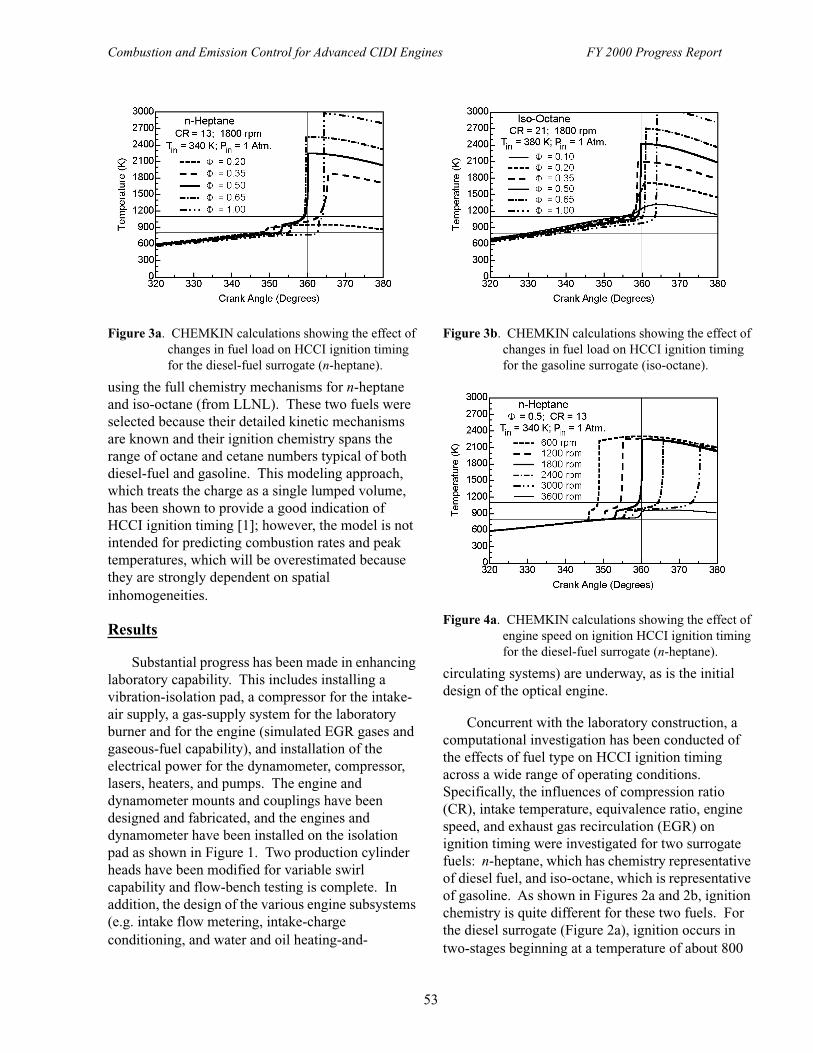
Combustion and Emission Control for Advanced CIDI Engines FY 2000 Progress Report
53
using the full chemistry mechanisms for n-heptane and iso-octane (from LLNL). These two fuels were selected because their detailed kinetic mechanisms are known and their ignition chemistry spans the range of octane and cetane numbers typical of both diesel-fuel and gasoline. This modeling approach, which treats the charge as a single lumped volume, has been shown to provide a good indication of HCCI ignition timing [1]; however, the model is not intended for predicting combustion rates and peak temperatures, which will be overestimated because they are strongly dependent on spatial inhomogeneities.
Results
Substantial progress has been made in enhancing laboratory capability. This includes installing a vibration-isolation pad, a compressor for the intake-air supply, a gas-supply system for the laboratory burner and for the engine (simulated EGR gases and gaseous-fuel capability), and installation of the electrical power for the dynamometer, compressor, lasers, heaters, and pumps. The engine and dynamometer mounts and couplings have been designed and fabricated, and the engines and dynamometer have been installed on the isolation pad as shown in Figure 1. Two production cylinder heads have been modified for variable swirl capability and flow-bench testing is complete. In addition, the design of the various engine subsystems (e.g. intake flow metering, intake-charge conditioning, and water and oil heating-and-
circulating systems) are underway, as is the initial design of the optical engine.
Concurrent with the laboratory construction, a computational investigation has been conducted of the effects of fuel type on HCCI ignition timing across a wide range of operating conditions. Specifically, the influences of compression ratio (CR), intake temperature, equivalence ratio, engine speed, and exhaust gas recirculation (EGR) on ignition timing were investigated for two surrogate fuels: n-heptane, which has chemistry representative of diesel fuel, and iso-octane, which is representative of gasoline. As shown in Figures 2a and 2b, ignition chemistry is quite different for these two fuels. For the diesel surrogate (Figure 2a), ignition occurs in two-stages beginning at a temperature of about 800
Figure 3a. CHEMKIN calculations showing the effect of changes in fuel load on HCCI ignition timing for the diesel-fuel surrogate (n-heptane).
Figure 3b. CHEMKIN calculations showing the effect of changes in fuel load on HCCI ignition timing for the gasoline surrogate (iso-octane).
Figure 4a. CHEMKIN calculations showing the effect of engine speed on ignition HCCI ignition timing for the diesel-fuel surrogate (n-heptane).
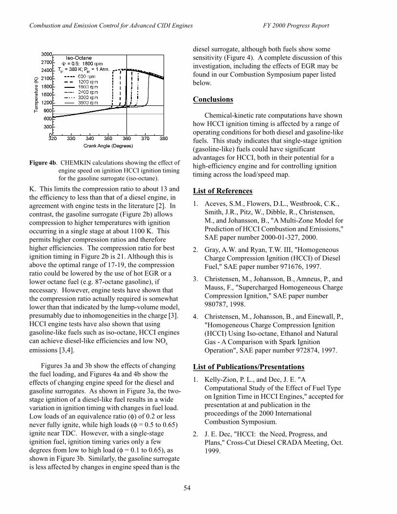
Combustion and Emission Control for Advanced CIDI Engines FY 2000 Progress Report
54
K. This limits the compression ratio to about 13 and the efficiency to less than that of a diesel engine, in agreement with engine tests in the literature [2]. In contrast, the gasoline surrogate (Figure 2b) allows compression to higher temperatures with ignition occurring in a single stage at about 1100 K. This permits higher compression ratios and therefore higher efficiencies. The compression ratio for best ignition timing in Figure 2b is 21. Although this is above the optimal range of 17-19, the compression ratio could be lowered by the use of hot EGR or a lower octane fuel (e.g. 87-octane gasoline), if necessary. However, engine tests have shown that the compression ratio actually required is somewhat lower than that indicated by the lump-volume model, presumably due to inhomogeneities in the charge [3]. HCCI engine tests have also shown that using gasoline-like fuels such as iso-octane, HCCI engines can achieve diesel-like efficiencies and low NOx emissions [3,4].
Figures 3a and 3b show the effects of changing the fuel loading, and Figures 4a and 4b show the effects of changing engine speed for the diesel and gasoline surrogates. As shown in Figure 3a, the two-stage ignition of a diesel-like fuel results in a wide variation in ignition timing with changes in fuel load. Low loads of an equivalence ratio (φ) of 0.2 or less never fully ignite, while high loads (φ = 0.5 to 0.65) ignite near TDC. However, with a single-stage ignition fuel, ignition timing varies only a few degrees from low to high load (φ = 0.1 to 0.65), as shown in Figure 3b. Similarly, the gasoline surrogate is less affected by changes in engine speed than is the
diesel surrogate, although both fuels show some sensitivity (Figure 4). A complete discussion of this investigation, including the effects of EGR may be found in our Combustion Symposium paper listed below.
Conclusions
Chemical-kinetic rate computations have shown how HCCI ignition timing is affected by a range of operating conditions for both diesel and gasoline-like fuels. This study indicates that single-stage ignition (gasoline-like) fuels could have significant advantages for HCCI, both in their potential for a high-efficiency engine and for controlling ignition timing across the load/speed map.
List of References
1. Aceves, S.M., Flowers, D.L., Westbrook, C.K., Smith, J.R., Pitz, W., Dibble, R., Christensen, M., and Johansson, B., "A Multi-Zone Model for Prediction of HCCI Combustion and Emissions," SAE paper number 2000-01-327, 2000.
2. Gray, A.W. and Ryan, T.W. III, "Homogeneous Charge Compression Ignition (HCCI) of Diesel Fuel," SAE paper number 971676, 1997.
3. Christensen, M., Johansson, B., Amneus, P., and Mauss, F., "Supercharged Homogeneous Charge Compression Ignition," SAE paper number 980787, 1998.
4. Christensen, M., Johansson, B., and Einewall, P., "Homogeneous Charge Compression Ignition (HCCI) Using Iso-octane, Ethanol and Natural Gas - A Comparison with Spark Ignition Operation", SAE paper number 972874, 1997.
List of Publications/Presentations
1. Kelly-Zion, P. L., and Dec, J. E. "A Computational Study of the Effect of Fuel Type on Ignition Time in HCCI Engines," accepted for presentation at and publication in the proceedings of the 2000 International Combustion Symposium.
2. J. E. Dec, "HCCI: the Need, Progress, and Plans," Cross-Cut Diesel CRADA Meeting, Oct. 1999.
Figure 4b. CHEMKIN calculations showing the effect of engine speed on ignition HCCI ignition timing for the gasoline surrogate (iso-octane).

Combustion and Emission Control for Advanced CIDI Engines FY 2000 Progress Report
55
3. J. E. Dec, HCCI Project Report, SIDI CRADA Meeting, Jan. 2000.
4. J. E. Dec and P. L. Kelly-Zion, "The Effects of Fuel Type on Ignition Timing in HCCI Engines," DOE CIDI Combustion, Emission Control, and Fuels Review, May 22-24, 2000.
5. J. E. Dec and P. L. Kelly-Zion, HCCI Project Report, Cross-Cut Diesel CRADA Meeting, May 31 - June 1, 2000.
List of Acronyms
CHEMKIN Name of chemical-kinetic codeCR Compression RatioEGR Exhaust Gas RecirculationHCCI Homogeneous Charge Compression
IgnitionLLNL Lawrence Livermore National
LaboratorySUV Sport Utility VehicleTDC Top Dead CenterVVT Variable Valve Timing

Combustion and Emission Control for Advanced CIDI Engines FY 2000 Progress Report
56
H. Camless Variable Valve Timing System for a High-speed CIDI Engine
Tsu-Chin (T-C.) TsaoMechanical and Aerospace Engineering DepartmentUniversity of California, Los AngelesBox 951597Los Angeles, CA 90095-1597(310) 206-2819, fax: (310) 206-2302, e-mail: [email protected]
DOE Program Manager: Kenneth Howden(202) 586-3631, fax: (202) 586-9811, e-mail: [email protected]
Subcontractor: University of California, Santa Barbara, CA
This Project addresses the following OTT R&D Plan Barriers and Tasks:
Barriers
A. NOx Emissions
B. PM Emissions
Tasks
2. Sensors and Controls
Objectives
• Develop a system dynamics model and simulation program for the proposed electrohydraulic camless valvetrain (ECV) actuating system.
• Develop electronic control methods for valve timing, lift, soft seating, and multiple valve operations.
• Integrate an instrumented variable valve timing system on an engine head with electronic drivers and control interface software. The 16-valve system shall be fully electronically driven via triggering from the crank angle of an engine running in parallel.
• Characterize the system performance envelope, energy consumption and sensitivity to environmental conditions through both simulation and experiment.
• Develop a system and control-oriented dynamic model of CIDI engines and investigate the feasibility of the control configurations and strategies using the proposed actuating system.
Approach
• Task 1: Perform system design, integration, and instrumentation.
• Task 2: Perform dynamic modeling, simulation, and control of the ECV actuating system.
• Task 3: Implement valve motion control and measure the valve performance and energy consumption. Compare the test results with Task 2 simulation results.
• Task 4: Perform system oriented engine-wide modeling of the actuating systems for CIDI engine operations.
• Task 5: Perform preliminary engineering and economic analysis according to the test and model simulation results.

Combustion and Emission Control for Advanced CIDI Engines FY 2000 Progress Report
57
Accomplishments
• The ECV system dynamics model and simulation programs have been developed and calibrated. The simulation results agree with experimental data.
• Adaptive nonlinear feedforward control for valve lift has been developed and implemented to successfully improve transient response time, eliminate transient overshoot, and enhance robust performance against operating condition changes.
• Eight-valve ECV subsystem has been demonstrated on the hardware test rig for simulated engine speed up to 5500 rpm.
• The ECV system has been fully electronically driven via triggering from the crank angle of an engine running in parallel. Furthermore, the ECV has been demonstrated to start up and run single cylinder engine combustion. The engine torque was controlled by the valve timing instead of by the throttle opening.
• The ECV system’s energy consumption has been measured to be comparable to that of cam driven valvetrain. The ECV has also been shown to operate using engine oil or diesel fuel instead of hydraulic oil.
• A system and control-oriented dynamic model of CIDI engines has been developed.
Future Directions
• Refine the system and component design for higher efficiency and consistency.
• Develop electronic control algorithms/software/hardware for valve timing, lift, soft seating, and closing control.
• Integrate the variable valve timing system on small high-speed CIDI engines for testing of camless CIDI engine operation.
• Characterize the ECV performance envelope, energy consumption, open loop and closed loop repeatability, and sensitivity to environmental conditions through both simulation and experiment.
• Develop and test system and control strategies for emission control and torque control of CIDI engines by using the variable valve timing capability.
Introduction
Most existing variable-timing systems, which perform a camshaft phase shift or a switch to another cam lobe profile, offer measurable improvements at some engine operating points [1,2]. A microprocessor controlled camless valvetrain, which continuously adjusts the parameters of valve motion with changing operating conditions, offers much more flexibility and potential benefits as they allow more complete optimization of engine events over the entire operating speed range. However, such devices can be complex, bulky, and relatively expensive, so their applications tend to be limited. An electrohydraulic camless valvetrain (ECV) was first conceived by Ford researchers [3]. This device
Figure 1. Electrohydraulic Camless Valvetrain Components

Combustion and Emission Control for Advanced CIDI Engines FY 2000 Progress Report
58
is compact and relatively simple. The goal of this research effort is to investigate the feasibility, address the technical challenges, and develop the enabling control capability of such a device for camless operation of small compression ignition direct injection (CIDI) engines.
Results
An experimental ECV has been completed. Figures 1 and 2 show the ECV components and the instrumented system. Dynamic models, simulation programs, and cyclic variability tests have been conducted and calibrated by the experimental data [4,5]. To account for the system non-linearities and the variations with the environmental conditions, and to realize the optimal engine operations at various loads and speeds, the engine valve motion must be precisely controlled. Adaptive nonlinear feedforward
control [6] was developed and tested successfully. Figure 3 demonstrates that the adaptive control has faster transient response and less overshoot (within 5 cycles) than PID (proportional-integral-derivative) control (about 10 cycles in the best case). Tests for fast speed transitions and fluids of different viscosities including diesel fuel were also successfully conducted.
To make use of the ECV’s potential benefits, the power required to run the system must be at least comparable to the camshaft frictional loss. The ECV power consumption is as follows:
Solenoid electrical power consumption + (Intake Lift + Exhaust Lift) * 2 * piston area * (1- ECV hydraulic recovery %) / hydraulic supply efficiency
Figure 2. Experimental Setup
Figure 3. Transient response for valve lift step changes
Figure 4. Predicted Energy Recovery Improvement by Increasing the Solenoid Speed
Figure 5. Camless Engine Torque Control Experimental Test by Variable Intake Closing Time

Combustion and Emission Control for Advanced CIDI Engines FY 2000 Progress Report
59
The energy recovery for the ECV system was measured to be about 10% for the present solenoid valves. The electrical power required to operate the solenoids was also measured. Using these figures, the ECV power consumption in turn was calculated. The worst case (maximum lift for full load) ECV power is similar to that of the finger rocker arms, but larger than the rolling finger followers. Faster solenoid closing time would generate high hydraulic energy recovery, as predicted by the model prediction shown in Figure 4 [6]. To further reduce the power consumption, the valve leakage must be reduced and the solenoid response must be increased.
The ECV was mounted on an engine to test single cylinder start-up and firing. During these tests the torque of the engine was controlled with the ECV valve timing with the throttle fully open, as Figure 5 shows [6]. Models for engine air breathing and control for cylinder-to-cylinder balancing have also been developed [7].
Conclusions
The electrohydraulic camless valvetrain proposed in this project offers a continuously variable and independent control of all aspects of valve motion. Freedom to optimize all parameters of valve motion for each engine operating condition is expected to result in better fuel economy, higher torque and power, improved idle stability, lower exhaust emissions and a number of other benefits and possibilities. The results obtained from this investigation suggest the technical feasibility for use in CIDI engines is good. Precise and agile valve motion control is of critical importance to make use of the variable valve timing and variable valve lift capability for optimal engine operations. Further research efforts should be directed to improving the valvetrain dynamic response, soft seating, and energy efficiency, and developing a prototype camless CIDI test engine for emission and torque control and performance evaluation.
List of References
1. Ahmad T. and Theobald M. A., "A Survey of Variable Valve Actuation Technology," SAE Paper No. 891674.b
2. Asmus T., "Perspectives on Applications of Variable Valve Timing", SAE paper 910445.
3. Schechter M. M. and Levin M. B., 1996, "Camless Engine," SAE Paper No. 960581.
4. Kim D., Anderson M., Tsao T. C., and Levin M. "A Dynamic Model of a Springless Electrohydraulic Camless Valvetrain System," SAE paper 97024
5. Anderson M., Tsao T.-C. ,and Levin M., "Adaptive Lift Control for a Camless Electrohydraulic Valvetrain," SAE Paper No. 981029.
6. Tai C., "Adaptive Feedforward with Feedback Control of an Electrohydraulic Camless Valvetrain," M.S. Thesis, University of Illinois at Urbana-Chmpaign, IL, 1999.
7. Ashhab M. S., Stefanopoulou A. G., Cook J., and Levin M., "Camless Engine Cotrol for Robust Unthrottled Operation," SAE Paper No. 981031.
List of Publications/Presentations
1. Tai C., "Adaptive Nonlinear Feedforward with Feedback Control of an Electrohydraulic Camless Valvetrain," M.S. Thesis, University of Illinois at Urbana-Chmpaign, IL, 1999.
2. Tsao, T-C., "Variable Valve Timing System for Camless Engine Operations," Cooperative Automotive Research for Advanced Technology Forum, Troy Mich., September, 1999.
3. Tai, C., Tsao, T-C., Levin, M. B., "Adaptive Nonlinear Feedforward Control of an Electrohydraulic Camless Valvetrain," American Control Conference, Chicago, IL., June 2000.
List of Acronyms
CIDI compression ignition direct injectionECV electrohydraulic camless valvetrainBMEP brake mean effective pressurePID proportional-integral-derivative

Combustion and Emission Control for Advanced CIDI Engines FY 2000 Progress Report
60
I. Low-Friction Coatings for CIDI Fuel Injection System Components
George R. Fenske (primary contact), Oyelayo Ajayi, John Woodford, and Ali ErdemirArgonne National Laboratory 9700 South Cass Avenue, ET-212Argonne, Illinois 60439(630) 252-5190, fax: (630) 252-4798, e-mail: [email protected]
DOE Program Manager: Kathi Epping(202) 586-7425, fax (202) 586-9811, e-mail: [email protected]
DOE Program Manager: Pat Davis(202) 586-8061, fax (202) 586-9811, e-mail: [email protected]
This Project addresses the following OTT R&D Plan Barriers and Tasks:
Barriers
C. Cost
Tasks
1a. Advanced Fuel Systems
Objectives
• Determine the impact of advanced fuel system strategies (advanced designs and low-emission fuels) on the reliability and durability of materials and surface treatments of critical fuel system components.
• Evaluate the performance of amorphous carbon coatings and other advanced surface treatments subjected to low-emission fuels.
• Determine and resolve critical issue(s) relating to the scale-up of advanced surface modification processes used to improve the reliability and durability of critical fuel system components.
• Determine the effect of EGR on the tribological properties of engine lubricants and characterize the potential of advanced surface treatments to improve reliability and durability of critical engine components subjected to EGR contaminated lubricants.
Approach
• Perform benchtop friction and wear tests to characterize the friction and wear properties of baseline materials and coatings subjected to tribological environments prototypical of advanced fuel systems and fuels.
• Deposit near frictionless carbon (NFC), commercial diamondlike carbon, and other commercial coatings (e.g. CrN, TiN, etc.), and, evaluate tribological performance.
• Deposit NFC (and commercial coatings) on prototype components for reliability/durability evaluation on fuel system rigs.
• Procure and modify commercial-size plasma-assisted deposition rig for NFC coatings.
• Validate production of NFC coatings with large-batch size plasma assisted chemical vapor deposition (PACVD) unit.
• Transfer technology to industrial partner(s).
• Characterize engine lubricants exposed to differing levels of EGR.

Combustion and Emission Control for Advanced CIDI Engines FY 2000 Progress Report
61
• Perform benchtop tests to characterize tribological properties of materials exposed to EGR.
• Correlate benchtop test results with field results.
• Develop advanced materials and surface treatments for high EGR levels.
Accomplishments
• Protocols for evaluation of materials, and coated components were selected and developed at ANL.
• Preliminary benchtop tribological testing of baseline materials, NFC, and limited commercial coatings in diesel fuels completed.
• Prototype fuel system components were coated and tested.
• Commercial PACVD unit procurement was initiated.
• Completed preliminary analysis of engine lubricants exposed to different levels of EGR
Future Directions
• Analysis and comparison of failure modes & wear modes of baseline and advanced coatings under stringent tribological conditions (low-lubricity fuels and EGR-contaminated lubricants).
• Demonstration of NFC coating on a large batch basis.
Introduction
Reduction of emissions from CIDI engines will require low sulfur and low aromatic fuels to minimize degradation of aftertreatment devices, reduce particulate formation, and minimize lubricant degradation. Such fuels, however, have poor lubricity, and can increase the occurrence of catastrophic scuffing failure as well as reduce long-term durability of critical components. Reducing emissions from CIDI engines may also require low-emission lubricant additive packages that have lower levels of sulfur, phosphorous, and metallic based compounds critical for anti-wear and low-friction properties. Furthermore, more aggressive engine environments resulting from: the recirculation of combustion products (particulates and acids) through the use of EGR to reduce NOx, downsizing and weight reduction of components, higher injection pressures, and higher speeds will exacerbate the ability of current materials and lubricants to meet reliability and durability requirements
Approach
The development of NFC coatings for advanced CIDI fuel system components involves optimization
of the NFC deposition process to minimize catastrophic scuffing and long-term wear. Benchtop friction and wear protocols were employed at Argonne to first characterize the scuffing and wear performance of current materials to serve as a baseline for comparison with NFC coatings as well as other commercially available (e.g. DLCs, CrN, TiN, etc.) coatings. Commercial coatings applied to benchtop samples are obtained from different suppliers and subjected to the same test protocols as those for the baseline and NFC coated specimens to obtain information on the scuffing severity index (the product of the critical load, velocity, and friction coefficient at the point where scuffing occurs), as well as the wear rate.
Figure 1. Photograph of different engine components being coated with NFC coatings
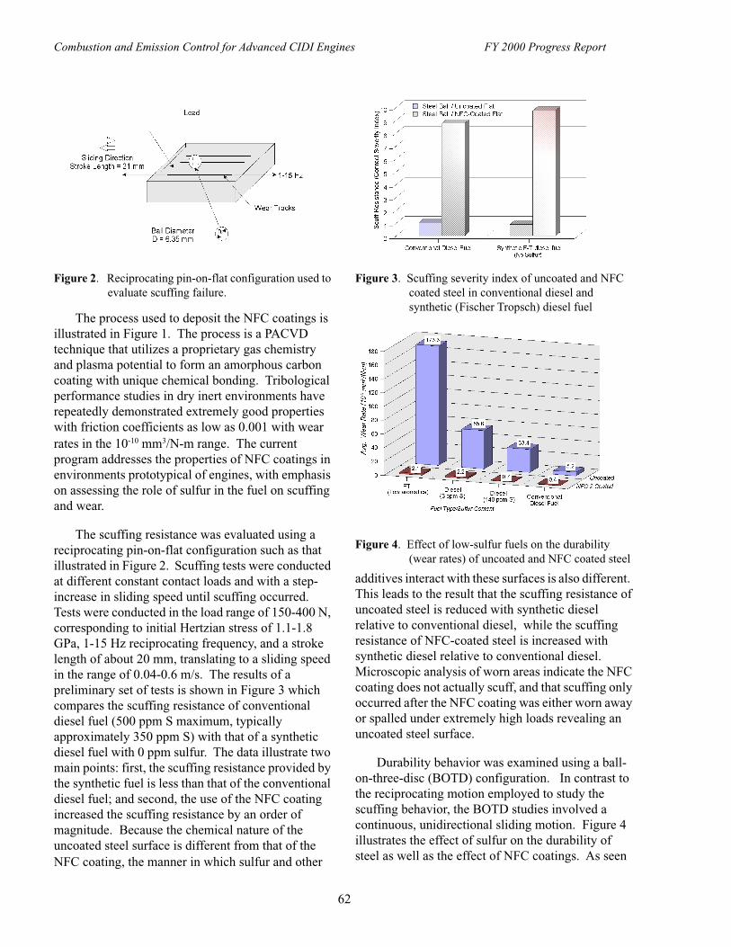
Combustion and Emission Control for Advanced CIDI Engines FY 2000 Progress Report
62
The process used to deposit the NFC coatings is illustrated in Figure 1. The process is a PACVD technique that utilizes a proprietary gas chemistry and plasma potential to form an amorphous carbon coating with unique chemical bonding. Tribological performance studies in dry inert environments have repeatedly demonstrated extremely good properties with friction coefficients as low as 0.001 with wear rates in the 10-10 mm3/N-m range. The current program addresses the properties of NFC coatings in environments prototypical of engines, with emphasis on assessing the role of sulfur in the fuel on scuffing and wear.
The scuffing resistance was evaluated using a reciprocating pin-on-flat configuration such as that illustrated in Figure 2. Scuffing tests were conducted at different constant contact loads and with a step-increase in sliding speed until scuffing occurred. Tests were conducted in the load range of 150-400 N, corresponding to initial Hertzian stress of 1.1-1.8 GPa, 1-15 Hz reciprocating frequency, and a stroke length of about 20 mm, translating to a sliding speed in the range of 0.04-0.6 m/s. The results of a preliminary set of tests is shown in Figure 3 which compares the scuffing resistance of conventional diesel fuel (500 ppm S maximum, typically approximately 350 ppm S) with that of a synthetic diesel fuel with 0 ppm sulfur. The data illustrate two main points: first, the scuffing resistance provided by the synthetic fuel is less than that of the conventional diesel fuel; and second, the use of the NFC coating increased the scuffing resistance by an order of magnitude. Because the chemical nature of the uncoated steel surface is different from that of the NFC coating, the manner in which sulfur and other
additives interact with these surfaces is also different. This leads to the result that the scuffing resistance of uncoated steel is reduced with synthetic diesel relative to conventional diesel, while the scuffing resistance of NFC-coated steel is increased with synthetic diesel relative to conventional diesel. Microscopic analysis of worn areas indicate the NFC coating does not actually scuff, and that scuffing only occurred after the NFC coating was either worn away or spalled under extremely high loads revealing an uncoated steel surface.
Durability behavior was examined using a ball-on-three-disc (BOTD) configuration. In contrast to the reciprocating motion employed to study the scuffing behavior, the BOTD studies involved a continuous, unidirectional sliding motion. Figure 4 illustrates the effect of sulfur on the durability of steel as well as the effect of NFC coatings. As seen
Figure 2. Reciprocating pin-on-flat configuration used to evaluate scuffing failure.
Figure 3. Scuffing severity index of uncoated and NFC coated steel in conventional diesel and synthetic (Fischer Tropsch) diesel fuel
Figure 4. Effect of low-sulfur fuels on the durability (wear rates) of uncoated and NFC coated steel

Combustion and Emission Control for Advanced CIDI Engines FY 2000 Progress Report
63
in Figure 4, as the sulfur content of the diesel fuel is reduced to 140 ppm S to 3 ppm S, and then to 0 ppm S (Fischer-Tropsch - FT), the wear rate of an uncoated hardened steel increases by a factor of 34. One sees a similar trend for the NFC coated discs, however, the magnitude of the increase is significantly lower (a factor of approximately 5), and the absolute values for the NFC coated surfaces are all significantly lower than the best uncoated steel and conventional diesel fuel. In other words, the highest wear rate (2.1) for the NFC coated samples (for FT fuel) was less than half that of the lowest wear rate (5.2) for the uncoated steel and conventional diesel fuel.
The reliability (e.g the ability to withstand short-term catastrophic failure such as scuffing) and durability (e.g. the ability to withstand long-term wear that leads to gradual degradation) of fuel delivery components are not only affected by sulfur, but also by aromatic compounds. Sulfur is known to provide extreme pressure protection by the formation of protective boundary layer films and thus will have a more dramatic impact on improving scuffing resistance. Aromatics increase the effective viscosity of the fuel resulting in thicker fluid films that minimize interactions between surface asperities and hence have a greater impact on long term wear. The petroleum-based fuels used in these tests had different levels of aromatics, while the FT fuel contained no aromatics. Thus, some of the differences seen in these figures are in part due to different aromatic contents (although all, with the exception of the FT fuel, were in the 20 to 30% level). However, tests are currently in progress using a series of DECSE fuels that were formulated in such a manner that the only variable is the sulfur content (ranging from 3 ppm to 471 ppm).
A series of diesel injector plungers were coated and delivered to our industrial partner for a series of seizure tests, in which an injector is paired with an undersized injector body to ensure a tight fit. The assembled unit is then subjected to a series of runs in which the injection pressure is gradually increased until the injector seizes. For a typical uncoated, hardened plunger, seizure occurs at approximately 1000 bar, while for a plunger coated with a commercial TiN coating, seizure occurs at approximately 3000 bar. The seizure limit for the
first set of NFC coated plungers exceed 3500 bar, far above any values observed to date.
Because of these exceptional results, a number of fuel system suppliers are interested in using this technology in production. We are currently collaborating with a number of PACVD equipment OEMs to transfer the NFC process technology in this area, and anticipate receiving a state-of-the-art unit that will be modified to accept the NFC process.
Future Directions
Efforts are also being pursued to evaluate the properties of NFC coatings for other engine components. One such program is with a diesel engine OEM. The focus of this project is to evaluate the effect that EGR will have on the lubricating properties of engine lubricants that are exposed to higher levels of soot and acid. Traditional approaches to solve the EGR problem would be to increase the detergent levels and acid neutralizing additives in the oil. However, in light of the need to minimize S, P, and metallic compounds in engine lubes due to their deleterious effect on aftertreatment devices, this may not be a viable approach. Consequently efforts are in progress to determine the impact of using higher levels of EGR on the lubricating properties of engine lubes, and determining the role of advanced coatings as a mean to mitigate these effects.
List of Publications
1. O.O. Ajayi, G.R. Fenske, A. Erdimir, J. Woodford, J. Sitts, and K. Griffey, "Low-Friction Coatings for Air Bearings in Fuel Cell Air Compressors", in SAE Paper 2000-01-1536.
2. M.F. Alzoubi, O.O. Ajayi, O.L. Eryilmaz, O. Ozturk, A. Erdimir, and G.R. Fenske, "Tribological Behavior of Near-Frictionless Carbon Coatings in High- and Low-Sulfur Diesel Fuels", SAE Paper 2000-01-1548.
3. A. Erdimir, O. Ozturk, M. Alzoubi, J. Woodford, O. O. Ajayi, and G.R. Fenske, "Near-Frictionless Carbon Coatings for Use in Fuel Injectors and Pump Systems Operating with Low-Sulfur Diesel Fuels", SAE Paper 2000-01-0518.
4. O.O. Ajayi, M. Alzoubi, A. Erdimir, G.R. Fenske, O.L. Eryilmaz, and S. Zimmerman,

Combustion and Emission Control for Advanced CIDI Engines FY 2000 Progress Report
64
"Tribological Performance of NFC Coatings under Oil Lubrication", SAE Paper 2000-01-1547.
List of Presentations
1. A. Erdimir, O.L. Eryilmaz, and G.R. Fenske, "Synthesis of Diamondlike Carbon Films with Superlow Friction and Wear Properties", presented at 46th International Symposium, AVS, October 25-29, 1999, Seattle, WA.
2. A. Erdimir, O.L. Eryilmaz, I.B. Nilufer, and G.R. Fenske, "Synthesis of Superlow Friction Carbon Films from Highly Hydrogenated Methane Plasmas", presented at International Conference on Metallurgical Coatings and Thin Films, April 9-14, 2000, San Diego, CA.
List of Acronyms
ANL Argonne National LaboratoryBOTD Ball on three discCIDI Compression Ignition Direct
InjectionDECSE Diesel Emission Control-Sulfur
EffectsDLC Diamond-Like CarbonEGR Exhaust Gas RecirculationFT Fischer-Tropsch Diesel FuelNFC Near-Frictionless CoatingsOEM Original Equipment ManufacturerP PhosphorusPACVD Plasma assisted chemical vapor
depositionS Sulfur

Combustion and Emission Control for Advanced CIDI Engines FY 2000 Progress Report
65
J. Fuel Spray Measurement Using X-Rays
Jin Wang (primary contact), Ramesh Poola, and Roy CuencaArgonne National Laboratory9700 South Cass AvenueArgonne, IL 60439(630) 252-9125, fax: (630) 252-9303, e-mail: [email protected]
DOE Program Manager: Kathi Epping(202) 586-7425, fax (202) 586-9811, e-mail: [email protected]
This Project addresses the following OTT R&D Plan Barriers and Tasks:
Barriers
A. NOx Emissions
B. PM Emissions
Tasks
1. Fuel Systems R&D
Objectives
• Understand the fuel structure and dynamics in the region close to nozzles with small orifice diameter operated at high injection pressure.
• Develop highly quantitative and time resolved methods to achieve the above goal.
• Establish a knowledge base regarding spray breakup mechanisms and droplet interactions as a key to realistic computational modeling.
Approach
• Stage 1: Study the feasibility of using synchrotron x-rays for imaging diesel fuel sprays in a time-resolved manner (with time resolution of better than 1 microsecond).
• Stage 2: Analyze the image data for qualitative evaluation of the spray characteristics.
• Stage 3: Use 2-dimensional x-ray detectors to collect the radiographic data more efficiently.
• Stage 4. Understand high-speed sprays by theoretical modeling and computational approaches.
Accomplishments
• Evaluated sprays of a Bosch injector under various injection conditions with both high spatial and temporal resolution.
• Collected the x-ray spray image data using 2-D detectors successfully.
Future Directions
• Develop x-ray optics suited for 2-D data collection to improve the productivity of the experiments.
• Perform the spray measurement under higher ambient pressure.
• Develop 2-phase models near the injection nozzles.

Combustion and Emission Control for Advanced CIDI Engines FY 2000 Progress Report
66
Introduction
Detailed analysis of the in-cylinder fuel spray process has been recognized as an important step in the overall aim of increasing combustion efficiency and reducing emission of pollutants, in particular from diesel engines. This has spurred considerable activity in the development of both optical and non-optical fuel injector spray measurement techniques. Despite significant advances in laser diagnostics over the last 20 years, the region close to the nozzle has remained impenetrable to experiments designed to acquire quantitative information due to multiple scattering caused by the large number and high density of droplets in the region. While other researchers are looking into the possibility of using lasers of ultra-high power and ultra-short pulse width to study this region, we report here on the development of a new non-intrusive and quantitative technique to characterize the dense part of the fuel spray using monochromatic x-ray absorption techniques. X-rays are highly penetrative in materials composed of extremely dense droplets made of low-Z materials (materials made up of low atomic weight substances). This makes x-rays a most suitable tool for fuel spray studies to overcome the difficulties, such as multiple scattering, encountered by conventional methods utilizing visible light. At the Advanced Photon Source (APS), we have developed a technique, utilizing x-ray absorption of monochromatic radiation, to quantitatively determine the fuel density distribution in this optically impenetrable region with a time resolution better than one microsecond. The current quantitative measurements constitute the most detailed near-nozzle study of a fuel spray to date.
Approach
The fuel spray was generated using a high-pressure injector typical of that found in a compression ignition, direct injection (CIDI) engine. The diesel fuel used in the test was doped with a cerium-containing additive in order to increase its x-ray absorption. Injection was performed into a spray chamber filled with inert gas at atmospheric pressure and at room temperature. SF6, a very heavy gas, was used to create a relatively dense ambient environment in the injection chamber. The experiments were performed at the 1-BM beamline
of the Synchrotron Radiation Instrumentation Collaborative Access Team (SRI-CAT) at APS. A 5.989 keV x-ray beam was initially focused and then collimated by a pair of X-Y slits to a size of 500 µm (horizontal) by 50 µm (vertical). The transient x-ray attenuation signal due to the fuel spray was measured by an avalanche photodiode (APD). The APD response was proportional to the beam intensity over the range used in our experiment and was recorded every 2 ns by a digitizing oscilloscope. Since the APD is a point detector, the injection chamber was scanned vertically and horizontally with respect to the x-ray beam, allowing the beam to probe various positions within the spray plume. The x-ray absorption technique using a monochromatic beam is distinguished from conventional measurements by the quantitative nature of the measurement. With proper calibration, the x-ray absorption directly yields the absolute fuel mass quantity in the beam and the mass distribution.
A plot of the time-dependent x-ray transmission at positions 1 and 6 mm from the nozzle on the spray axis are shown in Figure 1. For the data taken at 1 mm from the nozzle, it can be clearly seen that the spray arrives and leaves the beam spot at t = 0.11 and 0.5 ms, respectively. The leading edge of the fuel spray appears very abruptly, indicating a very distinct boundary between ambient gas and fuel spray and a compressed layer after the sharp edge. At 6 mm from the nozzle on the spray axis, the front edge of the spray arrives at the measuring point at a later time (0.19 ms). The delay can be used to calculate the
Figure 1. Time evolution of the x-ray transmission on the spray axis 1 mm (solid square) and 6 mm (open square) from the nozzle
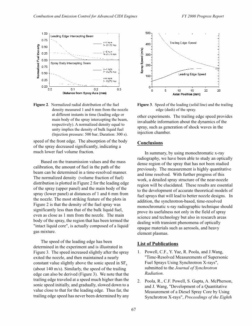
Combustion and Emission Control for Advanced CIDI Engines FY 2000 Progress Report
67
speed of the front edge. The absorption of the body of the spray decreased significantly, indicating a much lower fuel volume fraction.
Based on the transmission values and the mass calibration, the amount of fuel in the path of the beam can be determined in a time-resolved manner. The normalized density (volume fraction of fuel) distribution is plotted in Figure 2 for the leading edge of the spray (upper panel) and the main body of the spray (lower panel) at distances of 1 and 6 mm from the nozzle. The most striking feature of the plots in Figure 2 is that the density of the fuel spray was significantly less than that of the bulk liquid fuel, even as close as 1 mm from the nozzle. The main body of the spray, the region that has been termed the "intact liquid core", is actually composed of a liquid/gas mixture.
The speed of the leading edge has been determined in the experiment and is illustrated in Figure 3. The speed increased slightly after the spray exited the nozzle, and then maintained a nearly constant value slightly above the sonic speed in SF6 (about 140 m/s). Similarly, the speed of the trailing edge can also be derived (Figure 3). We note that the trailing edge traveled at a speed much higher than the sonic speed initially, and gradually, slowed down to a value close to that for the leading edge. Thus far, the trailing edge speed has never been determined by any
other experiments. The trailing edge speed provides invaluable information about the dynamics of the spray, such as generation of shock waves in the injection chamber.
Conclusions
In summary, by using monochromatic x-ray radiography, we have been able to study an optically dense region of the spray that has not been studied previously. The measurement is highly quantitative and time resolved. With further progress of this work, a detailed spray structure of the near-nozzle region will be elucidated. These results are essential to the development of accurate theoretical models of fuel sprays that will lead to better nozzle designs. In addition, the synchrotron-based, time-resolved monochromatic x-ray radiographic technique should prove its usefulness not only in the field of spray science and technology but also in research areas dealing with transient phenomena of optically opaque materials such as aerosols, and heavy element plasmas.
List of Publications
1. Powell, C.F., Y. Yue, R. Poola, and J.Wang, "Time-Resolved Measurements of Supersonic Fuel Sprays Using Synchrotron X-rays", submitted to the Journal of Synchrotron Radiation.
2. Poola, R., C.F. Powell, S. Gupta, A. McPherson, and J. Wang, "Development of a Quantitative Measurement of a Diesel Spray Core by Using Synchrotron X-rays", Proceedings of the Eighth
Figure 2. Normalized radial distribution of the fuel density measured 1 and 6 mm from the nozzle at different instants in time (leading edge or main body of the spray intercepting the beam, respectively). A normalized density equal to unity implies the density of bulk liquid fuel (Injection pressure: 500 bar; Duration: 300 s).
Figure 3. Speed of the leading (solid line) and the trailing edge (dash) of the spray.

Combustion and Emission Control for Advanced CIDI Engines FY 2000 Progress Report
68
International Conference on Liquid Atomization and Spray Systems, California, July 2000.
3. Yue, Y., C.F. Powell, R. Poola, and J. Wang, "Quantitative Measurement of Diesel Fuel Spray Characteristics in the Near-Nozzle Region by Using X-ray Absorption", submitted to Atomization and Sprays.
4. Schaller, J.K., U. Kunzi, C.F. Powell, Y. Yue, R. Poola, and J. Wang, "Investigations of the Diesel Injection Using Synchrotron X-rays for Quantitative Measurement of the Mass Distribution and a Piezo Electrical Sensor to Probe the Jet Force", Proceedings of ILASS-Europe 2000, Darmstadt, Germany, September 2000.
List of Acronyms
2-D Two-dimensionalAPD Avalanche photodiodeAPS Advanced Photon SourceCIDI Compression Ignition Direct
InjectionkeV Thousand electron voltsSF6 Sulfur hexaflourideSRI-CAT Synchrotron Radiation
Instrumentation Collaborative Access Team

Combustion and Emission Control for Advanced CIDI Engines FY 2000 Progress Report
69
IV. EXHAUST GAS NOX EMISSION CONTROL R&D
A. Non-Thermal Plasma-Assisted Catalysis
M. Lou Balmer (primary contact), Russ Tonkyn, Steve Barlow, Gary Maupin, and Alexander PanovPacific Northwest National LaboratoryP.O. Box 999, MSIN K8-93Richland, WA 99352(509) 376-2006, fax: (509) 376-5106, e-mail: [email protected]
Stephen D. NunnOak Ridge National LaboratoryP.O. Box 2008, M/S 6087Oak Ridge, TN 37831-6087(865) 576-1668, fax: (865) 574-8271, e-mail: [email protected]
DOE Program Manager: Kathi Epping (202) 586-7425, fax (202) 586-9811 email: [email protected]
CRADA Partner: Low Emissions Technologies Research and Development Partnership (Member Companies: Ford Motor Company, General Motors, and DaimlerChrysler Corporation)Michael J. Royce (Primary Contact) DaimlerChrysler Corporation Power Train Engineering CIMS 482-01-07, 800 Chrysler Drive Auburn Hills, MI 48236-2757 PH : (248) 576-4996; FX : (248) 576-2182; email: [email protected]
This Project addresses the following OTT R&D Plan Barriers and Tasks:
Barriers
A. NOx Emissions
B. PM Emissions
Tasks
4b. Non-thermal Plasma R&D
5e. R&D on PM Reducing Technologies
Objective
• Develop an aftertreatment system that will achieve 90% NOx reduction using less than 5% of the engine power on a compression ignition direct injection (CIDI) engine. The program supports goals of the Partnership for a New Generation of Vehicles (PNGV).
Approach
• Synthesize and test new catalysts in simulated and real diesel exhaust. A highly active plasma catalyst is critical to meeting the program goals.
• Measure plasma catalyst activity in simulated and real diesel exhaust.
• Investigate the role of NO2 and other species (partial oxidation products and hydrocarbon radicals) on NOx reduction activity on select catalysts.
• Develop prototype reactors.

Combustion and Emission Control for Advanced CIDI Engines FY 2000 Progress Report
70
• Evaluate prototype reactors for energy efficiency and durability.
• Measure the efficiency of plasma catalyst systems for particulate removal.
Accomplishments
• New catalysts have been discovered that reduce NOx over a wider temperature window (150-400oC) when placed in or down-stream from a plasma reactor. The equivalent fuel penalty for NOx reduction is less than 5%.
• A catalyst combination resulted in reduced formation of formaldehyde and N2O (to negligible levels).
• Two sets of engine tests on a PNNL prototype plasma catalyst system were completed. Performance varied from as high as 55% NOx reduction to as low as 20% NOx reduction over the five vehicle test points.
• A new intermediate scale reactor was built and tested.
• Particulate removal (92-96%) using a packed bed plasma catalyst system was demonstrated over a range of EGR conditions.
• Complete nitrogen balance was obtained for the best catalysts and catalyst combinations.
• Designed and made new forming dies for fabricating the latest iteration of ceramic dielectric components for the experimental non-thermal plasma reactor.
• Initiated tests to establish a commercially viable ceramic component fabrication procedure using low temperature co-fired material from a commercial source and a high-temperature ceramic green tape produced in-house at ORNL.
Future Directions
• Continue to develop higher activity catalysts that are durable over long periods of time in a real diesel environment.
• Develop improved prototype plasma reactor system for engine testing in late 2001.
• Continue to probe mechanisms of NOx reduction over catalyst surfaces.
• Investigate ways to optimize both the NOx and particulate removal efficiency of plasma catalyst systems.
Introduction
Previous work on this program showed that plasma-catalyst systems can reduce NOx emissions in simulated diesel exhaust; however, improvements in the efficiency and design of the plasma reactor systems, as well as in the efficiency of the catalysts, are necessary for vehicle applications. Research in FY00 had three primary foci: 1) evaluating plasma catalyst prototype systems on real engine exhaust, 2) improving catalyst and reactor efficiencies, and 3) revealing mechanisms that lead to NOx reduction using select catalysts. In addition, some scoping
studies were performed to determine the extent of particulate removal possible with a plasma.
FY00 Results
Catalyst development efforts in FY2000 focussed on completely characterizing the product distribution from catalyst B, which was discovered last year, and on synthesizing and evaluating new catalytic materials. A new catalyst, designated catalyst C, which has high NOx reduction activities over a temperature range that compliments the activity range of catalyst B was discovered. As

Combustion and Emission Control for Advanced CIDI Engines FY 2000 Progress Report
71
shown in Figure 1, this catalyst reduces 80-90% of NOx at temperatures ranging from 300-500oC. When catalyst C is combined with catalyst B, a high NOx conversion over temperatures ranging from 150-500oC can be achieved as illustrated in Figure 2. Small amounts of formaldehyde and minor amounts of N2O are formed as by-products of the NOx reduction reaction over catalyst B. Combination of catalysts B and C results in reduction of formaldehyde formation. In addition, there is insignificant N2O formation over catalyst C (Figure 2).
A prototype double dielectric barrier plasma reactor was tested for NOx reduction activity on exhaust from a 1996 1.9L Volkswagen TDI diesel
engine. Catalyst B was coated onto 300 cell/inch cordierite monoliths provided by DaimlerChrysler Corporation and was placed downstream from the region in which the plasma was generated. Engine tests were performed at Oak Ridge National Laboratory. Certification diesel fuel with a sulfur level of 350 ppm was used for engine testing.
Figure 3 shows the NOx conversion at a universal engine test point where the conditions and exhaust gas concentrations are described in Tables 1 and 2. The total NOx conversion was measured by: 1.) a chemiluminescent NOx analyzer (NOx that does not show up as NO or NO2 is assumed to be reduced), and 2.) an FTIR (NOx that is not detected as N2O, NO2, NO or other nitrogen-containing species is assumed reduced to N2). The background value is the amount of NOx that was removed between the inlet and outlet of the device when no power is delivered to the plasma. This background may arise
Figure 1. Thermal and Plasma Assisted NOx Conversion as a Function of Temperature for Catalyst C
Figure 2. NOx Conversion, N2O and Formaldehyde Formation as a Function of Temperature for Catalyst B Mixed with Catalyst C
Figure 3. NOx Reduction from Diesel Engine Exhaust for a 2-Stage Plasma Catalyst System with and without Added Propylene
Table 1. Engine Conditions
Revolutions per Minute (rpm) 1,900
Torque (ft-lb) 61
Horsepower (hp) 22
Air/Fuel Ratio 28
Airflow (scfm) 59-63
Fuel Flow (cc/sec) 1.3
Temperature into Device (oC) 276-279
Temperature out of Device (oC) 171-215

Combustion and Emission Control for Advanced CIDI Engines FY 2000 Progress Report
72
from thermal conversion, adsorption, or calibration differences between the inlet and outlet CLAs. There was a small amount of drift in the engine-out NOx concentration during the testing period. Because the percent NOx conversion value depends on the initial NOx concentration, this drift was taken into account in the "corrected" FTIR value shown in Figure 3. It can be seen from Figure 3 that with no added hydrocarbon (engine out C1:NOx = 0.4:1) there is no significant reduction of NOx. When 870 ppm propylene (2610 ppm on a C1 basis) is added to the exhaust, 47-57% NOx reduction is measured. A minimum NOx reduction of 20% was observed at a test point with high space velocity (25,000 hr-1) and temperature (300oC).
The total hydrocarbon consisted of 140 ppm C1 from engine-out exhaust plus added propylene. The maximum NOx conversion was achieved at a C1:NOx ratio of 6:1 with no additional benefit from increasing the ratio to 9:1. (Figure 4) This result is in good agreement with bench data on catalyst B which
showed that maximum NOx conversion can be obtained at a C1:NOx ratio of 6. The power required to run the reactor was estimated from the wall plug power and was on the order of 15 J/L or 2.7% engine-out (0.6 HP). The combined impact on FTP fuel economy from the increased electrical load and the addition of HC reductant is estimated to be six percent at this stage of development.
Conclusions
PNNL and the LEP have developed plasma assisted catalyst systems that can reduce 70% NOx over a large temperature range (150-500oC) on simulated diesel exhaust. Engine tests on a first stage prototype system were successfully completed. The plasma assisted catalyst system achieved 20-57% NOx conversion depending on the engine conditions.
List of Publications
1. M.L. Balmer, R.G. Tonkyn, G. Maupin, I. Yoon, A. Kolwaite, S. Barlow, N. Domingo, J.M. Storey, J. Hoard, and K. Howden, "Non-Thermal Plasma System Development for CIDI Exhaust Aftertreatment", SAE 2000-01-1601.
2. J.W. Hoard, Evgenii Kalashnikov, Joseph Szente, and Diane Podsiadlik, "Cluster Formation by Barrier Discharge in Simulated Engine Exhaust Gas at High Temperature", Applied Physics Letters, vol. 76 no. 21, 22 May 2000.
3. M.L. Balmer, R.G. Tonkyn, I. Yoon, A. Kolwaite, S. Barlow, G. Maupin, and J. Hoard, "NOx Destruction Behavior of Select Materials when Combined with a Non-Thermal Plasma", SAE 1999-01-3640, October 1999.
4. M.L. Balmer, R.G. Tonkyn, I. Yoon, A. Kolwaite, S.Barlow, G. Maupin, and J. Hoard, "Diesel NOx Reduction Activity of Select Materials when Combined with a Plasma", Proceedings of the Diesel Engine Emissions Reduction Workshop, July 1999.
5. John Hoard, Leaf Worsley, and William Follmer (ASI), "Electrical Characterization of a Dielectric Barrier Discharge Plasma Device", SAE paper 1999-01-3635.
6. John Hoard and M. Lou Balmer (PNNL), "Plasma-Catalysis for Diesel NOx Remediation",
Table 2. Engine-Out Exhaust Gas Concentrations
Oxygen 11%
Carbon Dioxide 7%
Carbon Monoxide 150 ppm
Hydrocarbon as C1 140 ppm
NOx 320 ppm
Figure 4. Percent NOx reduction as a function of the ratio of C1/NOx in the exhaust. Engine-out C1 was 140 ppm and additional C1 was achieved with added propylene

Combustion and Emission Control for Advanced CIDI Engines FY 2000 Progress Report
73
Journal of Advanced Oxidation Technologies, December 1999.
7. John Hoard, Tim Wallington, James Ball, Michael Hurley, Ken Wodzisz, and M. Lou Balmer, "Role of Methyl Nitrate in Plasma Exhaust Treatment", Environmental Science and Technology, October 1999.
8. M. Lou Balmer, "Towards Clean Cars: Plasma Destruction of Vehicle Pollutants", PNNL/DOE Onsite Review, September 1, 1999.
List of Presentations
1. Hoard, John; "Plasma-Catalyst for Diesel Emission Reduction", invited presentation for the 2000 International Chemical Congress of the Pacific Basin Societies, Symposium #211 Plasma Chemistry and Technology for Green Manufacturing, Pollution Control, and Applications, Honolulu, HI, December 14-19, 2000.
2. Balmer, M. Lou; Alexander Panov; Steven Yoon; Ana Kolwaite; and Russ Tonkyn; "Plasma Catalytic Lean NOx Reduction with Zeolite and Alumina Catalysts", 2000 National Laboratory Catalysis Research Conference (NLCAT 2000), Argonne, IL, October 12-13, 2000.
3. Hoard, John; "Plasma-Catalyst Aftertreatment for Lean Engine Exhaust", section in SAE Diesel Engine TOPTEC: Emissions Challenges for the Future, Indianapolis, IN, September 26-27, 2000.
4. Hoard, John; Paul Laing; M. Lou Balmer; and Russ Tonkyn; "Fuel Economy Impact of Plasma-Catalyst Versus Active Lean NOx Aftertreatment", DOE Diesel Engine Emission Reduction Workshop, San Diego, CA, August 2000.
5. Panov, Alexander; Steven Yoon; Ana Kolwaite; Russ Tonkyn; and M. Lou Balmer; "NOx Reduction Behavior of Alumina and Zeolite Catalysts in Combination with a Non-Thermal Plasma", DEER 2000, San Diego, CA, August 21-24, 2000.
6. Tonkyn, Russ; S. Barlow; Steven Yoon; Alexander Panov; Ana Kolwaite; and M. Lou Balmer; "Lean NOx Reduction by Plasma
Assisted Catalysis", DEER 2000, San Diego, CA, August 21-24, 2000.
7. Yoon, Steven; Russ Tonkyn; Alexander Panov; Ana Kolwaite; S. Barlow; and M. Lou Balmer; "Reaction Mechanism Study of Lean NOx Reduction using Plasma Catalysis", American Chemical Society, Washington, DC, August 20-24, 2000.
8. Balmer, M. Lou; "Plasma Catalysts for NOx Reduction", Invited Talk, GlobeEx 2000 International Energy Conference, Las Vegas, NV, July 23-28, 2000.
9. Hoard, Bretz, and Bryzik (poster presentation made by Bryzik), "Non-Thermal Plasma Catalysts for NOx Destruction, Central Region ACS Meeting, Cincinnati, OH, May 16-19, 2000.
10. Balmer, M.L.; R. Tonkyn; G. Maupin; I. Yoon; A. Kolwaite; S. Barlow; N. Domingo; J.M. Storey; J. Hoard; and K. Howden; "Non-Thermal Plasma System Development for CIDI Exhaust Aftertreatment", SAE 2000 FutureCar Conference, Arlington, VA, April 2-6, 2000.
11. M. Lou Balmer, "NOx Reduction of Select Materials When Combined with A Non-Thermal Plasma", Ford Motor Company, November 2, 1999.
12. M. Lou Balmer, R. Tonkyn, S. Yoon, A. Kolwaite, S. Barlow, G. Maupin and T. Orlando, "NOx Reduction of Select Materials when Combined with a Non-Thermal Plasma", Society of Automotive Engineers, Fall Fuels and Lubricants Meeting, October 25-28, 1999, Toronto, Canada.
13. M. Lou Balmer, R. Tonkyn, S. Yoon, A. Kolwaite, S. Barlow, G. Maupin and T. Orlando "Diesel NOx Reduction Activity of Select Materials When Combined with a Plasma", Castine, ME, July 5-9, 1999.
14. John Hoard, Colleen Bryzik, and M. Lou Balmer, "Plasma-Catalysis for Lean NOx: Comparison of Two Catalysts", DOE Diesel Engine Emission Reduction Workshop, Castine, Maine, July 1999.

Combustion and Emission Control for Advanced CIDI Engines FY 2000 Progress Report
74
15. John Hoard, "Plasma-Catalysis for Exhaust Aftertreatment in Lean Engines", MIT Engine and Fuels Consortium presentation, Auburn Hills, MI, March 1999.
List of Acronyms
C1 per carbon basisCIDI Compression Ignition Direct
InjectionCLA Chemiluminescent NOx AnalyzerCRADA Cooperative Research and
Development AgreementEGR Exhaust Gas RecirculationFTIR Fourier Transform Infrared
SpectrometryHP HorsepowerJ/L Joules/LiterPNGV Partnership for the Next Generation
of Vehiclesppm parts per million

Combustion and Emission Control for Advanced CIDI Engines FY 2000 Progress Report
75
B. Sulfur-Tolerant NOx Adsorber System Development
John M. Storey (primary contact), Mike Kass Oak Ridge National LaboratoryP.O. Box 2009, MS 8087Oak Ridge, TN 37831-8087(423) 574-0574, fax: (423) 574-2102, email: [email protected]
DOE Program Manager: Kathi Epping(202) 586-7425, fax: (202) 586-9811, e-mail: [email protected]
Subcontractor: GoalLine Environmental Technologies, Knoxville, TN
This Project addresses the following OTT R&D Plan Barriers and Tasks:
Barriers
A. NOx Emissions
Tasks
4a. NOx Adsorber R&D
4e. R&D on NOx Reducing Technologies
Objectives
• Develop and construct prototype device for test on ORNL engine test stand.
• Develop a regeneration strategy.
• Carry out measurements of NOx control effectiveness and regeneration by-products in ORNL engine dyno lab.
Approach
• Subcontract to GoalLine Environmental Technologies to develop and construct a dual channel prototype NOx adsorber.
• Develop a reformer and regeneration strategy that would utilize diesel fuel to regenerate the prototype NOx adsorber.
• Installation of the prototype device on an engine test stand and measure NOx removal effectiveness and regeneration by-products at selected engine operating conditions.
Accomplishments
• Preliminary evaluation data on adsorber performance under controlled laboratory conditions were generated by GoalLine and provided to ORNL.
• A prototype sulfur trap-NOx adsorber system was developed and built by GoalLine for light-duty vehicle applications. This prototype was delivered to ORNL.
• The prototype system was installed on a light-duty engine test stand and an initial evaluation was completed.

Combustion and Emission Control for Advanced CIDI Engines FY 2000 Progress Report
76
Future Directions
• Development and test of simpler and smaller devices based on the technology developed by GoalLine.
• Incorporation of diesel fuel reformer for regeneration.
• Additional work with sulfur traps to determine durability and sulfur fate.
Introduction
The proposed light-duty vehicle emission standards for 2007 require very low fleet average NOx emission levels (0.07 g/mile). However, most current NOx reduction systems are unable to meet the fleet average 2007 standards for full useful life certification. Of the current technologies being developed for NOx reduction from diesel engines, NOx adsorber technology offers very promising means of achieving the fleet average 2007 NOx emission standards.
NOx adsorbers work on the principal of selected chemical adsorption. In a typical adsorber system NO and NO2 gas molecules are adsorbed on the surface until all the available sites are filled. When the surface becomes saturated, NOx is no longer removed from the gas stream. At this point, the adsorber is regenerated by flowing a reducing gas mixture over its surface. During regeneration, the NOx on the surface is reduced via three-way catalysis to molecular nitrogen (N2) which is released into the gas stream. Sulfur (in the form of SO2), however, also attaches to the adsorber surface and reduces the number of sites available for NOx pickup. Unfortunately, this sulfur is not removed during regeneration and the amount of sulfur increases on the surface as the adsorber ages. As a result, adsorber performance decreases with increased sulfur loading.
Sulfur trap and NOx adsorber systems were developed by GoalLine Environmental Technologies and tested under controlled laboratory conditions. A prototype was developed and delivered to ORNL for engine evaluation. The ORNL experimental efforts have focused on measuring the removal of NOx emitted from a light-duty engine and the characterization of the gas chemistry occurring during regeneration.
Approach
GoalLine Environmental Technologies developed a NOx adsorber system that consists of a sulfur trap placed upstream of a NOx adsorber. The sulfur trap removes the gaseous sulfur, thereby preventing the NOx adsorber from becoming poisoned. This system was evaluated under controlled laboratory conditions and the performance of the sulfur trap and NOx adsorber during adsorption
Figure 1. NOx capacity of GoalLine system as function of exhaust temperature.
Figure 2. Released NOx, SO2, and N2O gas concentrations during regeneration.

Combustion and Emission Control for Advanced CIDI Engines FY 2000 Progress Report
77
and regeneration were characterized. These efforts led to the development of a prototype device which was sent to ORNL to be tested on a light-duty diesel engine.
The NOx adsorber capacity was found to be temperature dependent as shown in Figure 1. The exhaust temperature was controlled through engine loading and the levels of NOx were measured using bench analytical equipment and FTIR spectroscopy. Regeneration was performed using a mixture of 10% hydrogen in nitrogen at a space velocity of 2000/h. During regeneration, NOx and N2O were immediately released into the gas stream; while SO2 was released after 40 seconds of regeneration (see Figure 2). The regenerated levels of SO2 and NOx were also affected by the exhaust temperature. Regeneration at high temperature was observed to release more SO2 and NOx than at a lower temperature. Interestingly, the release of N2O is substantially higher at the lower temperatures. Earlier work with lean NOx catalysts has shown a similar tendency for N2O formation at low temperature. Restraining N2O formation will clearly need to be considered for future NOx adsorber development.
Conclusions
NOx adsorber systems incorporating sulfur traps offer a promising means of reducing NOx levels. This system has shown the potential to reduce NOx in the range of 90 to 95 percent, including emissions during regeneration. This level of performance should be sufficient to allow a diesel light-duty vehicle to meet the Tier 2 fleet average NOx standard.
The effect of fuel sulfur can be minimized with this system and it is expected that lower sulfur fuel will enable this technology even further. The sulfur released during regeneration is in the form of SO2 and not sulfate PM.
Currently, N2O emissions are in the range of 0.01 to 0.1 g/mile, which is similar to typical spark ignition light-duty vehicles. The formation of N2O during regeneration will need to be investigated for future research efforts. This may result in changes in adsorber design or reductant chemistry.
List of Acronyms
FTIR Fourier Transform Infrared Spectrometry
NOx Oxides of nitrogenORNL Oak Ridge National LaboratorySO2 Sulfur dioxide

Combustion and Emission Control for Advanced CIDI Engines FY 2000 Progress Report
78
C. Reduction of NOx Emissions for Lean-Burn Engine Technology
Timothy J. Gardner (Primary Contact)Sandia National LaboratoriesCatalytic and Porous Materials DepartmentP.O. Box 5800, MS 1349Albuquerque, NM 87185(505) 272-7621, fax: (505) 272-7336, e-mail: [email protected]: Sandia National Laboratories, Albuquerque, New MexicoPrime Contract No.: DE-AC04-94AL85000
Ralph N. McGillOak Ridge National LaboratoryEngineering Technology Division, Power Systems Section P.O. Box 2009, MS 8087Oak Ridge, TN 37831(865) 574-4077, fax: (865) 574-2102, e-mail: [email protected]: Oak Ridge National Laboratory, Oak Ridge, TennesseePrime Contract No.: DE-AC05-96OR22464
Kevin C. OttLos Alamos National LaboratoryChemistry Division Actinides, Catalysis, and Separations Group, MS J514Los Alamos, NM 87545(505) 667-4600, fax: (505) 667-3314, e-mail: [email protected]: Los Alamos National Laboratory, Los Alamos, New MexicoPrime Contract No.: W-7406-ENG-36
DOE Program Manager: Kathi Epping (202) 586-7425, fax (202) 586-9811 email: [email protected]
CRADA Partner: Low Emissions Technologies Research and Development Partnership (Member Companies: Ford Motor Company, General Motors, and DaimlerChrysler Corporation)Michael J. Royce (Primary Contact) DaimlerChrysler Corporation Power Train Engineering CIMS 482-01-07, 800 Chrysler Drive Auburn Hills, MI 48236-2757 PH : (248) 576-4996; FX : (248) 576-2182; email: [email protected]
This Project addresses the following OTT R&D Plan Barriers and Tasks:
Barriers
A. NOx Emissions
Tasks
4a. NOx Adsorber R&D
Objectives
• Develop new catalyst technology to enable CIDI engines to meet EPA Tier 2 emission standards.
Approach
• Development of new catalyst materials for reducing NOx emissions in lean-burn exhaust environments, including:

Combustion and Emission Control for Advanced CIDI Engines FY 2000 Progress Report
79
- Hydrous metal oxide-supported catalysts, and
- Zeolite-supported catalysts.
• Evaluation of new catalyst materials in both bulk powder and monolith forms, including short term durability testing, and testing of prototype catalytic converters on diesel engine dynamometers.
• Scale-up of synthesis and processing of promising catalyst formulations to enable fabrication of prototype catalytic converters for engine dynamometer testing.
• Technology transfer of most promising catalyst formulations and processes to LEP CRADA partners.
Accomplishments
• LANL optimized several processing routes, metal ions, and supports for new Ferrierite (FER)-supported metal catalysts. A provisional U.S. patent application was filed for these new catalyst materials, covering formulations, preparation procedures, and potential catalytic applications.
• Successfully adapted FER-supported metal catalyst synthesis procedures to prepare monolith core samples with similar high NOx reduction activity over a broad temperature range.
• LANL catalyst samples were transferred to LEP partners for compositional tests, as well as determination of the adsorption vs. catalysis functionality of these materials with respect to both NOx and hydrocarbon species.
• Identified a unique water sensitivity associated with the new FER-supported metal catalysts. Further characterization is in progress.
• The LANL portion of this project was the winner of the 2000 National Laboratory CIDI R&D Award in recognition of outstanding achievement in research and development of lean NOx catalysts for CIDI emission control.
• The engine dynamometer test bed at ORNL was transitioned to a Mercedes 1.7 L diesel engine, which should be more representative of the engine-out emissions profile of the prototype PNGV vehicles.
• Extensive microstructural characterization of SNL and LANL catalysts in powder or monolith core form was completed at ORNL.
• LANL and SNL examined short-term hydrothermal and SO2 aging issues with FER-supported metal catalysts and Pt-based/HMO catalysts, respectively.
• SNL completed characterization studies on lower light-off temperature and wider temperature window Pt-based catalysts for lean-burn NOx reduction via hydrocarbons.
• Two different phases of technology transfer activities involving SNL materials have now been completed, covering a minimum of three different Pt-based/HMO catalyst formulations. A defined process now exists for use in future technology transfer activities.
• SNL completed fundamental studies aimed at a better explanation of the limitation of supported Pt catalysts for applications involving the lean-burn reduction of NOx via hydrocarbons.
Future Directions
• Extend current national laboratory/LEP CRADAs into the FY01-03 time frame (all current CRADAs expire by 2/01). Address lean-burn NOx reduction catalyst options and research approaches within funding limitations. Continue SCR of NOx via hydrocarbons effort with promising new catalysts.

Combustion and Emission Control for Advanced CIDI Engines FY 2000 Progress Report
80
• Retrofit of SNL NOx reduction reactor unit to support selective catalytic reduction testing capability with urea/ammonia reductant. Obtain benchmark urea/ammonia SCR catalyst formulations from catalyst suppliers.
• Begin catalyst development and testing efforts with SCR of NOx via ammonia, with initial emphasis on supported oxide catalysts and supported base metal catalysts. Goals are increased activity (> 90% at 200oC @ 25,000 h-1), lower catalyst light-off (125-150oC), to understand ammonia storage issues on catalyst/washcoats, and to determine hydrocarbon influence on the SCR of NOx via ammonia process.
• Understand water adsorption issues associated with LANL FER-supported metal catalyst materials and attempt to solve these problems via alterations of the zeolite structures, frameworks, topologies, or surface chemistry.
• Complete designed experiment regarding optimization of FER-supported metal catalyst preparation, add complete data to provisional patent application, and file U.S. patent application in final form.
• Continue microstructural analysis of new LANL and SNL catalysts at ORNL.
• Determine the possible effects of particulate matter (PM) on the NOx reduction performance of lean-burn NOx catalysts.
Introduction
This multi-partner effort has been continued under OAAT sponsorship and involves separate CRADAs between three national laboratories (Los Alamos National Laboratory [LANL], Oak Ridge National Laboratory [ORNL], and Sandia National Laboratories [SNL]) and the Low Emission Technologies Research and Development Partnership (LEP, composed of DaimlerChrysler Corporation, Ford Motor Company, and General Motors Corporation). These CRADAs are currently in their final year, although project extension into the FY2001-2003 time frame is planned. The project addresses reduction of CIDI engine NOx emissions using exhaust aftertreatment - identified as one of the key enabling technologies for CIDI engine success. The overall CRADA efforts are focused on the development and evaluation of new catalyst materials for reducing NOx emissions, specifically targeting the selection of appropriate catalyst materials to meet the exhaust aftertreatment needs of the PNGV vehicles.
With the new EPA Tier 2 emission standards scheduled to be in place starting in 2004, our program has now begun general redirection efforts to address new and potentially more efficient NOx reduction options for lean-burn exhaust
aftertreatment. This year we began program transition toward the selective catalytic reduction (SCR) of NOx by urea (or ammonia). Efforts related to SCR of NOx via hydrocarbons will continue as promising new catalysts are identified.
Los Alamos National Laboratory (LANL) Efforts
LANL’s work has focused on the development of new and stable zeolite-based catalysts for NOx reduction in lean-burn exhaust environments. This work is complementary to the SNL work since these non-precious metal catalysts are typically active for NOx reduction at higher temperatures than those of the Pt-based catalysts under investigation at SNL.
In FY1999, a new family of Ferrierite (FER) zeolite-supported non-precious metal catalysts that have both high apparent NOx reduction activity and a broad range of appreciable NOx conversion was discovered. Additional experiments then focused on the optimization of preparation procedures (both support pretreatment and metal addition) to enable reproducible FER-supported metal catalyst fabrication to support the filing of a provisional U.S. patent application.

Combustion and Emission Control for Advanced CIDI Engines FY 2000 Progress Report
81
In FY2000, the FER-supported metal catalyst synthesis procedures were successfully adapted to prepare monolith core samples with similar high apparent NOx reduction activity over a broad temperature range. Microstructural and compositional characterization of two different FER supports were performed at ORNL and General Motors, respectively, to aid overall characterization efforts. Short-term hydrothermal aging experiments at LANL indicated good catalyst stability at temperatures up to 750-850oC, where some deterioration in high temperature catalyst performance was observed. Standard LANL test conditions included 20 min isothermal holds to achieve steady state in an overall temperature ramp-down test mode.
Activity testing with these materials indicated a distinct possibility that the high apparent NOx conversion included contributions from both NOx adsorption, as well as SCR of NOx via hydrocarbons. An effort was therefore undertaken to determine the adsorption vs. catalysis functionality of these materials. Ford staff performed extensive transient tests with LANL catalyst samples to help understand these issues. Initial transient tests involved studying NOx adsorption capability by ramping up the catalyst temperature at a controlled rate (15oC/min) using a gas mix consisting of 75 ppm NO, 12% O2, and balance N2. These experiments were run both with and without H2O (5%) in the feed. The results of this experiment are shown below in Figure 1. Since no
hydrocarbon was used in these experiments, NOx removal in this case would involve an adsorption process. In the absence of water (labeled as 0% H2O), nearly all of the NO fed to the sample is adsorbed up to a temperature of ~250oC. Above 250oC, the NOx adsorption drops sharply and becomes negative, indicating NOx desorption from the sample. All of the NOx is desorbed from the sample by a temperature of 550oC. Separate experiments determined that the NOx desorbs predominantly as NO2. As shown in Figure 1, the addition of 5% H2O to the feed almost completely destroys the NOx adsorption capacity of the sample. This indicates that NO does not effectively compete with H2O for adsorption sites on the catalyst.
An experiment similar to that shown in Figure 1 was also performed in which 300 ppm of propylene (as C1) was added to the feed. In this case, at least some catalytic NOx removal would be expected due to the presence of the hydrocarbon. The results for these transient experiments are shown in Figure 2. Note that in this case apparent NOx conversion is plotted on the y axis; contributions from both adsorption and catalytic reaction are both included in this case. In the case of the feed without water (labeled Hydrocarbon with 0% H2O), the low temperature NOx profile is very similar to that observed in Figure 1. This indicates that it is highly likely that, even in the presence of the hydrocarbon, NOx is adsorbed on the catalyst under these
Figure 1. Results showing the effect of water (H2O) on the NOx adsorption behavior of a LANL FER-supported metal catalyst
Figure 2. Results showing the effect of water (H2O) on the apparent NOx conversion profile of a LANL FER-supported metal catalyst

Combustion and Emission Control for Advanced CIDI Engines FY 2000 Progress Report
82
conditions. Above 300oC, it is likely that NOx is converted via reaction with the hydrocarbon. Separate evidence under similar conditions indicates propylene also adsorbs on the FER-supported metal catalyst at low temperatures, with CO2 production beginning at 150oC and peaking at ~450oC. This indicates that the active region of catalytic lean-burn NOx reduction is at temperatures > 250-300oC. Other evidence generated at LANL indicates that this reaction may involve the nonselective production of nitrogen-containing hydrocarbons rather than selective catalytic reduction of NOx to N2. As in the case of Figure 1, the addition of water to the feed has a significant negative effect on the apparent NOx conversion, including both the region of high NOx adsorption (< 200oC) and the region of NOx conversion (> 250oC).
One of the interesting aspects of the Ford work was the discovery of the sensitivity of the FER-supported metal catalysts to H2O. Previous work at LANL using their standard temperature ramp-down test protocol with 20 min isothermal hold periods had not revealed a sensitivity of the catalysts to water in the feed. Additional work at LANL did reproduce the water sensitivity observed in the Ford tests, and the results of these experiments are shown below in Figure 3. The data in Figure 3 show that the temperature ramp-up test mode in the presence of H2O clearly produces the worst results, with the apparent NOx conversion at low temperature almost disappearing. In contrast, reasonable NOx conversion is achieved using any of the other test protocols shown in Figure 3, either with or without the presence of water. By comparing the Ford and LANL test protocols, it is possible to conclude that the sensitivity of the FER-supported metal catalysts to water depends on the nature of their exposure. Catalyst exposure to water at low temperature (<400oC), similar to the Ford test protocol, is extremely detrimental to catalyst performance. However, catalyst exposure to water at high temperature does not seem to significantly affect catalyst performance. Additional thermogravimetry studies at LANL showed that the water effect is reversible, but temperatures > 400oC are required to remove the H2O from the FER structure. The low temperature water sensitivity of these materials will be a significant barrier to their use in emissions
control devices, since alternate control strategies would need to be developed to minimize catalyst exposure to water at low temperatures (cold start, etc.).
Efforts are continuing to both further understand these water sensitivity issues, as well as trying to overcome them through changes in zeolite structure, topology, framework, and/or surface chemistry. Further automaker reactor testing is planned if less water-sensitive zeolite-based catalysts can be developed at LANL.
This project was the winner of the 2000 National Laboratory CIDI R&D Award in recognition of outstanding achievement in research and development of lean NOx catalysts for CIDI emission control.
Oak Ridge National Laboratory (ORNL) Efforts
ORNL’s continuing role in this project has been to provide characterization of catalyst performance, both in bench scale reactor testing and in an engine laboratory, in addition to microstructure characterization of catalysts using electron microscopy.
Over the last few years, at the suggestions of the industry partner team, the test bed has been
Figure 3. Results showing the effect of testing protocol on the NOx conversion observed with a LANL FER-supported metal catalyst. All data were collected after 20 min isothermal hold times at each temperature.

Combustion and Emission Control for Advanced CIDI Engines FY 2000 Progress Report
83
transitioned from the larger 7.3 L Navistar diesel engine to the 1.9 L Volkswagen (VW) TDI diesel engine and most recently to the Mercedes 1.7 L diesel engine. The engine-out emissions profile of this new engine is more representative of the conditions that will exist in the prototype PNGV vehicles. Figure 4 shows the Mercedes 1.7 L diesel engine test bed in the ORNL engine laboratory.
Over the last year, microstructural characterization was performed on several SNL and LANL catalysts (in both powder and monolith core form) at the High Temperature Materials Laboratory at ORNL. For the SNL materials, the nature, location, and morphology of additive phases to Pt-based/HTO:Si catalysts were examined, while the effect of support pretreatment procedures on the chemical composition and morphology of the LANL FER materials was also determined. To date, no conclusions can be drawn regarding microscopy of LANL catalysts in powder form versus catalytic activity measured on bench flow reactors. The outstanding electron microscopy facilities at ORNL continue to provide high quality service to the national laboratories as well as our CRADA partners.
Previous work with the VW 1.9 L TDI diesel engine determined that particulate matter (PM) emissions from this engine might be affecting catalyst performance. Higher PM emissions might be expected for this engine since the exhaust gas recirculation (EGR) mode was active for all test conditions. Experiments are in progress to compare the emissions profile of the Mercedes and VW TDI engines. The interaction between PM emissions and
the NOx reduction performance of lean-burn NOx catalysts (either SCR via hydrocarbons or urea/ammonia) will continue to be investigated in the future.
Sandia National Laboratories (SNL) Efforts
Technology transfer efforts with the SNL Pt-based/HMO catalysts were completed in the past year. The sum total of these efforts involved the transfer of a minimum of three different Pt-based/HMO catalyst formulations, including recent work with respect to special additives to Pt/HTO:Si catalysts that both lower light-off temperature and broaden the temperature window of appreciable NOx conversion. In general, it can be summarized that a significant breakthrough regarding lean NOx catalysis was not achieved with the SNL materials and process, although this result is more a function of the extremely aggressive EPA Tier 2 emissions standards than the specific attributes of Pt-based/HMO or other supported Pt catalysts. Significant benefits achieved by the technology transfer process were that these efforts added to the catalytic materials knowledge base and provided new insight, as well as providing a potential payoff with other catalyst materials and/or applications. Importantly, a process now exists for future technology transfer of
Figure 4. Mercedes 1.7 L diesel engine mounted on the engine dynamometer test bed at Oak Ridge National Laboratory
Species New Mix Old Mix
NOx 75 250
Total HC (ppm as C1) 600 2100
n-C8H18 (ppm as C1) 450 525 (C3H8)
C3H6 (ppm as C1) 150 1675
Total HC (as C1): NOx 8:1 8.4:1
Total C3H6 (as C1): NOx 2:1 6:1
CO (ppm) 600 400
H2 (ppm) 200 133
CO2 (%) 5.0 7.0
O2 (%) 12 8
H2O (%) 5.0 8.0
SO2 (ppm) 1.5 15
Space Velocity (cc/cc*h-1) 25,000 50,000
Table 1. Comparison of old and new mix simulated exhaust gas formulations representative of lean-burn gasoline and small displacement (1.1-1.5 L) CIDI engine exhaust, respectively.

Combustion and Emission Control for Advanced CIDI Engines FY 2000 Progress Report
84
LEP CRADA-developed catalyst formulations from the national laboratories to the LEP and their designated catalyst suppliers.
In response to FY1999 Peer Review Panel comments, fundamental studies related to the selective catalytic reduction of NOx over supported Pt catalyst materials were conducted in an effort to better explain the limitations of these materials for selective catalytic reduction of NOx via hydrocarbon reductants. Using a Pt/HTO:Si catalyst in monolith core form, we performed a series of experiments that isolated the effects of several key process variable differences between simulated exhaust gas formulations referred to as the old mix (lean burn gasoline) and new mix (small displacement CIDI engine). Table 1 shows the composition and process variable differences between the old mix and new mix simulated exhaust gas formulations. The new mix is based on averaged and weighted CIDI engine speed/load points typical of light-duty operation. The key differences between these formulations are the NOx concentration, the propylene (C3H6):NOx ratio, and the space velocity, all of which are significantly lower for the new mix relative to the old mix. These key differences are highlighted in Table 1.
Figure 5 shows the conversion profiles for the hydrocarbon (propylene and propane), CO, and NOx species using the old mix test conditions with a
typical Pt/HTO:Si catalyst. One important feature illustrated by Figure 5 is the strong coupling of the propylene oxidation and NOx reduction profiles, indicating the dominance of propylene as a reductant for NOx conversion. Relative to propylene, almost no conversion of NOx is observed in conjunction with either CO oxidation or propane oxidation. It would therefore be expected that process variable changes which retard or enhance the propylene oxidation reaction will similarly affect the NOx reduction efficiency. Another important feature of Figure 5 is that although NOx conversion is reasonable for the old mix formulation (~60%), values in excess of 85% are required to meet Tier 2 emission standards.
The cumulative effect of altering the variables described above (see annotated text in Figure 5) is to significantly reduce the maximum NOx conversion and to shift the location of the temperature of maximum NOx conversion to a much lower temperature, as indicated by the arrows superimposed on the NOx conversion profile in Figure 5, with the propylene:NOx ratio having the most significant effect. This cumulative effect is directly shown in Figure 6, which compares the NOx and propylene conversion profiles for the old vs. new mix conditions. In addition to the propylene
Figure 5. Typical conversion profiles for species of interest using the old mix test conditions with a supported Pt catalyst. The effect of altering each of the variables noted on the Figure is illustrated by the corresponding arrows.
Figure 6. Typical NOx and dominant hydrocarbon conversion profiles for species of interest in old vs. new mix formulations for a supported Pt catalyst. Note that the profiles representative of the new mix test conditions also include an n-octane oxidation profile (x symbols), in addition to both the propylene oxidation and NOx reduction profiles.

Combustion and Emission Control for Advanced CIDI Engines FY 2000 Progress Report
85
oxidation and NOx reduction profiles, an n-octane oxidation profile is also shown for comparison in the case of the new mix formulation. It is obvious, however, that n-octane is not effectively utilized by the supported Pt catalyst for NOx reduction, even though it is present in the new mix formulation at a level three times higher than the propylene (see Table 1). N-octane has only been shown to be an efficient reductant for NOx conversion over supported Pt catalysts at very high concentrations (~16:1 HC:NOx ratio on a C1 basis), which are unacceptable due to fuel penalty considerations.
In the case of the new mix results shown in Figure 6, the dominating effect of the low C3H6:NOx ratio results in very low maximum NOx conversion (~20%). The combined effects of the lower space velocity, the lower feed NOx concentration, and the lower C3H6:NOx ratio also significantly shift the temperature of maximum NOx conversion to lower temperature. An additional concern associated with lowering the temperature of maximum NOx conversion is that the selectivity of N2 production (as a result of NOx reduction) decreases as the temperature of maximum NOx conversion is lowered, with significant amounts of N2O being produced under these conditions. These overall results show that the activity of supported Pt catalysts in lean-burn NOx reduction by hydrocarbons is limited by both the type and quantity of hydrocarbon reductant. Small alkenes represent the most effective hydrocarbon reductants and on-board strategies for storage and/or production of these species, coupled with their delivery to the exhaust stream and catalytic converter unit, still should be considered feasible. However, few (if any) supported Pt catalyst systems utilizing reasonable quantities of hydrocarbon reductants have demonstrated the level of NOx reduction necessary to meet the Tier 2 emission standards. This fact makes it unlikely that supported Pt catalysts used in the selective catalytic reduction of NOx via hydrocarbons can be the sole solution to the emissions control needs of CIDI engines. Even with these limitations, one can easily envision a multicomponent emissions control scheme where these materials and catalytic processes can play an important role.
Sandia has also been involved in significant program redirection efforts toward utilizing catalytic processes involving the selective catalytic reduction of NOx by urea (or ammonia) for CIDI emissions control applications. These processes show great promise of achieving the levels of NOx conversion required to meet the Tier 2 emission standards. In FY2000, a gas phase FTIR spectrometer system for accurate determination of a wide variety of nitrogen-containing species was integrated into our existing NOx reduction reactor unit. This reactor unit has also been modified to accommodate an ammonia reductant feed and development efforts related to catalyst materials for selective catalytic NOx reduction via ammonia have been initiated. Catalyst screening activities utilizing the reactor test unit should begin in the fourth quarter of FY2000.
List of Presentations
1. T. J. Gardner, R. N. McGill, and K. C. Ott, "Reduction of NOx Emissions for Lean-Burn Engine Technology," Presentation at the DOE CIDI Engine Combustion, Emission Control, and Fuels R&D Review, Argonne, IL, May 22, 2000.
2. R. N. McGill and J. M. Storey, "Engine and Emission Control Enablers for High Efficiency Light-Duty CIDI Engines." Presented at ENERGEX2000 - The Eighth International Energy Forum, Las Vegas, NV, July 25, 2000.
3. T. J. Gardner and D. L. Mowery, "Challenges in Lean-Burn Automotive Exhaust Catalysis," Presented at ENERGEX2000 - The Eighth International Energy Forum, Las Vegas, NV, July 25, 2000.
List of Patents
1. K. C. Ott, N. C. Clark, and M. T. Paffett, "Catalyst and Process for Preparation of Catalysts for Lean Burn Engine Exhaust Abatement", Provisional U. S. Patent Application, Serial No. 60/162,431, October 28, 1999.
List of Awards
1. Kevin Ott, Noline Clark, and Jon Ran of Los Alamos National Laboratory received the 2000 National Laboratory CIDI R&D Award in

Combustion and Emission Control for Advanced CIDI Engines FY 2000 Progress Report
86
recognition of outstanding achievement in research and development of NOx catalysts for CIDI Engine Emission Control.
List of AcronymsoC Degrees CentigradeC1 Unit Carbon BasisC3H6 PropyleneC3H8 Propanecc Cubic CentimeterCO Carbon MonoxideCIDI Compression Ignition Direct
InjectionCRADA Cooperative Research and
Development AgreementEGR Exhaust Gas RecirculationEPA Environmental Protection AgencyFER FerrieriteFTIR Fourier Transform-Infrared FY Fiscal YearHC HydrocarbonHMO Hydrous Metal OxideHTO:Si Silica-Doped Hydrous Titanium
OxideL LiterLANL Los Alamos National LaboratoryLEP Low Emissions Technologies
Research and Development Partnership
min Minutesn-C8H18 Normal OctaneNOx Nitrogen Oxides (NO and NO2)ORNL Oak Ridge National LaboratoryPM Particulate MatterPNGV Partnership for a New Generation of
Vehiclesppm parts per million (volume basis)R&D Research and DevelopmentSNL Sandia National LaboratoriesTDI Turbo Direct InjectionVW Volkswagen

Combustion and Emission Control for Advanced CIDI Engines FY 2000 Progress Report
87
V. EXHAUST GAS PARTICULATE EMISSION CONTROL R&D
A. Optical Diagnostic Development for Exhaust Particulate Matter Measurements
Peter O. Witze (primary contact) and Robert M. GreenCombustion Research FacilitySandia National LaboratoriesPO Box 969, MS 9053Livermore, CA 94550-0969(925) 294-2691, fax: (925) 294-1004, e-mail: [email protected]
DOE Program Manager: Kathi Epping(202) 586-7425, fax: (202) 586-9811, e-mail: [email protected]
This Project addresses the following OTT R&D Plan Barriers and Tasks:
Barriers
B. PM Emissions
Tasks
2. Sensors and Controls
Objectives
• Develop real-time, engine-out particulate matter (PM) diagnostics for measuring size, number density and volume fraction.
• Transfer resulting technology to industry.
Approach
• Simultaneous measurements of laser-induced incandescence (LII) and laser elastic scattering (LES) are used to obtain the following PM aggregate parameters using the Rayleigh-Debye-Gans polydisperse fractal aggregate (RDG-PFA) approximation:
- particle volume fraction;
- diameter of primary particles;
- number density of primary particles;
- geometric mean of the number of primary particles per aggregate;
- geometric standard deviation of the number of primary particles per aggregate; and
- mass fractal dimension - radius of gyration of the aggregated primary particles.
• Laser-induced vaporization with Laser Elastic Scattering (LIVES) is used to measure the soluble organic fraction (SOF) of the PM.
• Off-the-shelf components are used to build a measurement system that can be easily duplicated by industry partners.
• Artium Technologies Inc. of Los Altos Hills, CA will commercialize the resulting technology.

Combustion and Emission Control for Advanced CIDI Engines FY 2000 Progress Report
88
Accomplishments
• LII signals have been characterized in a propane diffusion flame.
• Mini-dilution tunnel is operational on a 1.9 liter TDI diesel engine.
• LII-LES optical cell and data acquisition system is operational.
• Scanning mobility particle sizer (SMPS) for LII-LES calibration is operational.
• Initial phase of an LII-LES model has been completed.
• Real-time LII measurements of PM volume fraction have been demonstrated for engine startup, EGR and throttle transients.
• LIVES has been demonstrated for the real-time measurement of PM volume reduction in a diffusion flame.
Future Directions
• Complete LII-LES calibration/characterization with the SMPS.
• Improve the laser-heating/vaporization submodel in the LII-LES model.
• Develop LIVES as a technique for distinguishing SOF from solid-phase carbon.
• Develop experimental and modeling capability for RDG-PFA approximation for aggregate characterization.
• Apply the LII-LES and LIVES techniques to diesel exhaust.
Introduction
LII is a well-established technique for the measurement of PM volume fraction and primary particle size; it has been applied to both stationary burner flames and diesel engine combustion. Light from a high-energy pulsed laser is used to quickly heat the PM to its vaporization point, resulting in gray-body radiation that is proportional to the PM volume fraction; the cooling rate of the PM following laser heating is a measure of primary particle size. Simultaneous measurement of LES from the particles at several discrete angles relative to the incident laser beam can be used to obtain additional information regarding the characteristics of PM aggregates using the RDG-PFA approximation.
The advantages of LII-LES over conventional PM measurement techniques are that it can be applied in any environment (e.g., hot or cold, undiluted or diluted, etc.), it responds in real time, and is very sensitive to low PM concentrations (lower limit is estimated to be one part per trillion).
Approach
A schematic of the LII-LES experimental setup is shown in Figure 1. The second harmonic output of a Nd:YAG laser at 532 nm is used for excitation. The laser fluence is controlled using a half wave plate (HWP) and thin film polarizer (TFP). Three measurements are simultaneously obtained with fast photodetectors: 1) Incident temporal profile of the
Figure 1. Schematic of the LII-LES experimental setup.

Combustion and Emission Control for Advanced CIDI Engines FY 2000 Progress Report
89
laser pulse, detected from diffuse scattering through a neutral density filter (NDF); 2) LII signal, detected through a long-wave pass filter with a 570 nm cutoff; and 3) LES, detected through an NDF and an interference bandpass filter (BPF) centered at 532 nm. A photograph of the actual hardware is presented in Figure 2.
The exhaust sampling and dilution configuration are illustrated schematically in Figure 3. The engine exhaust was sampled approximately 0.3 m downstream of the muffler using a tube with the entrance oriented upstream to the flow direction. The tube provided a flow of exhaust gas through a sample line heated to 100oC to an ejector-pump diluter where the sample was diluted with heated, dry nitrogen at a nominal dilution ratio of 10. Upon exiting the diluter, the sample passed into both the optical cell where the LII and LES measurements were carried out, and the SMPS where the PM characteristics were also measured.
Results
Shown in Figure 4 are LII intensity measurements made during engine startup to demonstrate the real-time capabilities of LII. For these preliminary results the LII was not calibrated, but because it responds explicitly to PM volume fraction, the relative magnitudes of the measurements are quantitative.
As mentioned earlier, LII is employed in a regime where laser energy heats the carbon PM to its vaporization point. Ideally, the laser energy is limited
so there is negligible mass loss from the PM. However, because our data acquisition system is very fast, it is interesting to observe the LES signal at high laser fluences where there is measurable carbon mass loss. The long-dash curve shown in Figure 5 is the temporal profile of the incident laser intensity; the short-dash curve is the temporal profile of the LES. These curves have been normalized by their maxima, so that the difference in the two waveforms is the
Figure 2. Exhaust-port optical cell and laser-beam conditioning optics.
Figure 3. Schematic Diagram of the Exhaust-Sampling System Illustrating the Engine, Ejector-Type diluter, optical cell, and the SMPS.
Figure 4. Preliminary LII measurements obtained during engine startup.
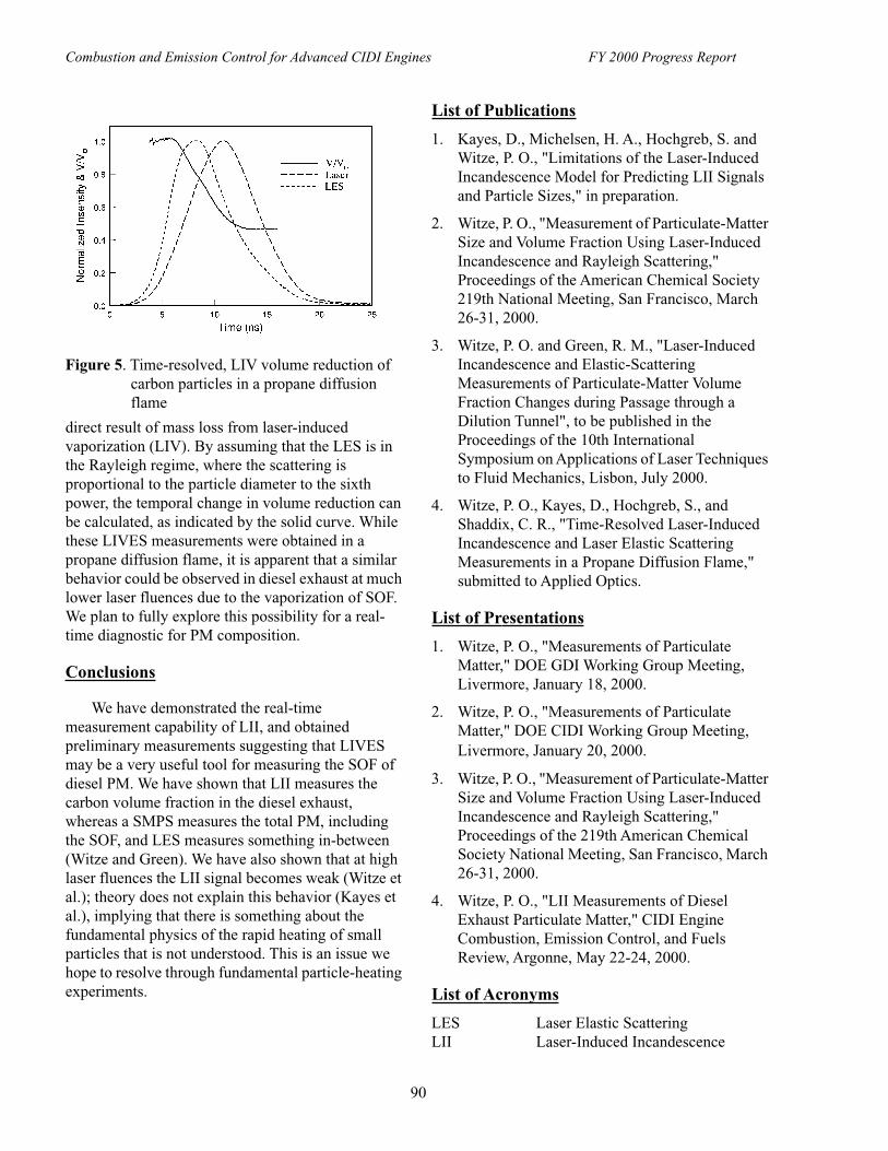
Combustion and Emission Control for Advanced CIDI Engines FY 2000 Progress Report
90
direct result of mass loss from laser-induced vaporization (LIV). By assuming that the LES is in the Rayleigh regime, where the scattering is proportional to the particle diameter to the sixth power, the temporal change in volume reduction can be calculated, as indicated by the solid curve. While these LIVES measurements were obtained in a propane diffusion flame, it is apparent that a similar behavior could be observed in diesel exhaust at much lower laser fluences due to the vaporization of SOF. We plan to fully explore this possibility for a real-time diagnostic for PM composition.
Conclusions
We have demonstrated the real-time measurement capability of LII, and obtained preliminary measurements suggesting that LIVES may be a very useful tool for measuring the SOF of diesel PM. We have shown that LII measures the carbon volume fraction in the diesel exhaust, whereas a SMPS measures the total PM, including the SOF, and LES measures something in-between (Witze and Green). We have also shown that at high laser fluences the LII signal becomes weak (Witze et al.); theory does not explain this behavior (Kayes et al.), implying that there is something about the fundamental physics of the rapid heating of small particles that is not understood. This is an issue we hope to resolve through fundamental particle-heating experiments.
List of Publications
1. Kayes, D., Michelsen, H. A., Hochgreb, S. and Witze, P. O., "Limitations of the Laser-Induced Incandescence Model for Predicting LII Signals and Particle Sizes," in preparation.
2. Witze, P. O., "Measurement of Particulate-Matter Size and Volume Fraction Using Laser-Induced Incandescence and Rayleigh Scattering," Proceedings of the American Chemical Society 219th National Meeting, San Francisco, March 26-31, 2000.
3. Witze, P. O. and Green, R. M., "Laser-Induced Incandescence and Elastic-Scattering Measurements of Particulate-Matter Volume Fraction Changes during Passage through a Dilution Tunnel", to be published in the Proceedings of the 10th International Symposium on Applications of Laser Techniques to Fluid Mechanics, Lisbon, July 2000.
4. Witze, P. O., Kayes, D., Hochgreb, S., and Shaddix, C. R., "Time-Resolved Laser-Induced Incandescence and Laser Elastic Scattering Measurements in a Propane Diffusion Flame," submitted to Applied Optics.
List of Presentations
1. Witze, P. O., "Measurements of Particulate Matter," DOE GDI Working Group Meeting, Livermore, January 18, 2000.
2. Witze, P. O., "Measurements of Particulate Matter," DOE CIDI Working Group Meeting, Livermore, January 20, 2000.
3. Witze, P. O., "Measurement of Particulate-Matter Size and Volume Fraction Using Laser-Induced Incandescence and Rayleigh Scattering," Proceedings of the 219th American Chemical Society National Meeting, San Francisco, March 26-31, 2000.
4. Witze, P. O., "LII Measurements of Diesel Exhaust Particulate Matter," CIDI Engine Combustion, Emission Control, and Fuels Review, Argonne, May 22-24, 2000.
List of Acronyms
LES Laser Elastic ScatteringLII Laser-Induced Incandescence
Figure 5. Time-resolved, LIV volume reduction of carbon particles in a propane diffusion flame

Combustion and Emission Control for Advanced CIDI Engines FY 2000 Progress Report
91
LIVES Laser-Induced Vaporization with Elastic Scattering
PM Particulate MatterRDG-PFA Rayleigh-Debye-Gans Polydisperse
Fractal AgglomerateSMPS Scanning Mobility Particle SizerSOF soluble organic fraction

Combustion and Emission Control for Advanced CIDI Engines FY 2000 Progress Report
92
B. Diesel Particle Scatterometer
Arlon Hunt (Primary Contact), Ian Shepherd, and John StoreyLawrence Berkeley National Laboratory70-108 University of CaliforniaBerkeley, CA 94720(510) 486-5370, fax (510) 486-7303, e-mail: [email protected]
DOE Program Manager: Kathi Epping(202) 586-7425, fax: (202)-586-9811, e-mail: [email protected]
ORNL Contact: John Storey(865) 574-0574, fax: (865) 574-2102, e-mail: [email protected]
This Project addresses the following OTT R&D Plan Barriers and Tasks:
Barriers
B. PM Emissions
Tasks
2. Sensors and Controls
Objectives
• Develop the Diesel Particle Scatterometer (DPS) for real-time diesel particle size measurements.
• Use the instrument to study particle characteristics as a function of engine type, load, RPM, fuel composition, and post-combustion processes (aftertreatment, dilution, etc.).
• Extend DPS capabilities in time, sensitivity, and application.
Approach
• Measure angle-dependent polarized light scattering from diesel exhaust, including the scattering intensity (millisecond response) and polarization transformations.
• Determine size distribution and the refractive and absorptive properties (n, k) of soot by comparing measured data with modeled scattering.
• Model soot scattering as: spheres - Mie scattering theory to fit data, agglomerates -represent clusters as coupled dipoles.
Accomplishments
• Installed and used two DPS instruments for real-time particle size measurements.
• Upgraded DPS hardware and software.
• Developed high-speed mode to follow rapid variations of particle loading.
• Used DPS to measure effectiveness of diesel afterburner and study engine cycling.
• Contacted instrument companies to begin commercialization of the DPS.
Future Directions
• Apply DPS to specific issues including engine type, operation, and fuel effects.

Combustion and Emission Control for Advanced CIDI Engines FY 2000 Progress Report
93
• Study performance of aftertreatment devices and exhaust dilution effects.
• Extend instrumental and software capabilities.
• Carry out DPS commercialization through tech transfer.
• Dialogue with California agencies.
Introduction
Particulate emissions from diesel engines are of increasing importance to regulatory agencies and to the public at large. Until now there has been very little real-time instrumentation to characterize diesel particulates as to their size distribution, composition, or morphology and almost no way to obtain meaningful measurements of engine emissions during transients. It has become clear that overall engine emissions in diesel engines are dependent on engine design, operation, and a trade-off between NOx and particulates. The NOx/PM trade-off is particularly relevant to determining the optimum EGR rates. We are developing and testing a new instrument, the Diesel Particle Scatterometer (DPS) for real-time diesel particle size and property measurements. We have designed, built and compared the DPS with other instruments and techniques for measuring diesel particulates. Presently we are operating two instruments, one at LBNL and one at ORNL. Figure 1 shows a photograph of the DPS. We are using the instruments to study how particle characteristics change with engine design, operation, fuel composition, and the effect of aftertreatment devices and dilution effects.
Approach
To characterize the diesel particles we measure angle-dependent polarized light scattering from diesel exhaust when illuminated with modulated laser light. In particular, the DPS measures both the scattering intensity and certain polarization transformations (matrix elements) of the incident to scattered laser light. The matrix elements are determined by the synchronous detection of the polarized light that is modulated at a 50 kHz rate by the polarization modulator and by the total scattered light. The detector output is digitized and analyzed by the software developed for the instrument. The three angle-dependent matrix elements are plotted on the computer monitor and are fit by modeled
calculations using a Levenburg-Marquardt optimization program. The result is plotted as a size distribution and refractive and absorptive optical properties of the particles. The absorptive component of the index of refraction gives a measure of the graphic carbon content of the exhaust particles. An important advantage of the instrument is the rapid response time; it has been tested at greater than 1 Hz data acquisition rate. This speed allows for the measurement of engine transients and even cylinder-to-cylinder to variations.
Results
We have installed and used two DPS instruments for real-time particle size and property measurements. This year we upgraded the software and installed additional detectors to improve the performance of the instrument. In addition to its normal operation discussed in last year’s report, we have also used a new, high-speed data acquisition mode to follow cylinder-to-cylinder variations of particle loading.
Figure 2 illustrates the sub-millisecond time response of the DPS to the exhaust generated at different exhaust gas recirculation (EGR) rates by a four-cylinder Volkswagen TDI engine operated at ORNL at a range of EGR rates. The total time shown
Figure 1. Diesel Particulate Scatterometer

Combustion and Emission Control for Advanced CIDI Engines FY 2000 Progress Report
94
for each graph is about 100 milliseconds. These measurements show the dramatic increase in particle loading with a small change in EGR rate and indicates that it may be possible to develop a very sensitive EGR control sensor based on the current instrument.
A further set of tests on this engine demonstrates the ability of the DPS in its high speed data acquisition mode to resolve particle loading variation due to changes in engine speed and load. Figure 3 shows the time variation of light scattering intensity during the test. Note the sharp transient when the running conditions change from idle to cruise.
The DPS was also used to determine the effectiveness of a prototype diesel afterburner being developed by Grahn Industries of Palo Alto, California. Figure 4 presents the change in particle size during this test and demonstrates the burn-out of the soot particles achieved in the afterburner.
Instrument companies have been contacted to determine their interest in commercialization of the DPS and copyright and patent applications have been submitted. A brochure package created by the LBNL Technology Transfer Department has been distributed to over 400 businesses/organizations and responses to the brochure are now accumulating.
Collaborations continue with: Prof. R. Dibble at the U.C. Berkeley Engine Laboratory (alternative fuels); Dr. R. Manliev of the Illinois Institute of Technology (instrument calibration); and Prof. P. Hull of Tennessee State University (particulate modeling with neural nets and coupled dipole model).
Figure 2. Particle Loading at Two EGR Rates (One Engine Cycle, VW TDI CIDI Engine)
Figure 3. DPS Response at Three Engine Operating Conditions
Figure 4. Particle Mean Radius as a Function of Afterburner Temperature

Combustion and Emission Control for Advanced CIDI Engines FY 2000 Progress Report
95
Conclusions
The DPS was upgraded by the addition of new detectors and the incorporation of improved data acquisition and analysis software. A high-speed data acquisition mode was developed to follow rapid changes in particle loading to resolve cylinder-to-cylinder variations. Successful measurements of the effects of EGR rate and engine load and speed on particulate loading were conducted in a VW-TDI engine. A possible EGR control sensor based on the current instrument was identified. The DPS was also used to determine the effectiveness of a prototype Diesel exhaust afterburner in reducing particulate emissions. Instrument companies were contacted for commercialization of the DPS.
List of Publications
1. A.J. Hunt, I.G. Shepherd, and J. M. Storey, "Rapid, In Situ Characterization of Diesel Particulates," Windsor Workshop on Transportation Fuels, Toronto, Ontario, Canada, June, 1999.
2. A.J. Hunt, I.G. Shepherd, and J. M. Storey, "Diesel Particle Scatterometer," DOE CIDI Engine Combustion, Emission Control, and Fuels Review, Argonne National Laboratory, May, 2000.
List of Acronyms
DPS Diesel Particulate ScatterometerEGR Exhaust Gas RecirculationLBNL Lawrence Berkeley National
LaboratoryNOx Oxides of NitrogenORNL Oak Ridge National LaboratoryRPM Revolutions per MinuteTDI Turbocharged Direct Injection

Combustion and Emission Control for Advanced CIDI Engines FY 2000 Progress Report
96
C. The Effect of Injector and In-Cylinder Conditions on Soot Formation in CIDI Engines
Dennis L. SiebersSandia National LaboratoriesP.O. Box 969, MS 9053Livermore, CA 94551-9053(925) 294-2078, fax: (925) 294-1004, e-mail: [email protected]
DOE Program Manager: Kathi Epping(202) 586-7425, fax: (202) 586-9811, e-mail: [email protected]
DOE Program Manager: Gurpreet Singh(202) 586-2333, fax: (202) 586-4166, e-mail: [email protected]
This Project addresses the following OTT R&D Plan Barriers and Tasks:
Barriers
A. NOx Emissions
B. PM Emissions
Tasks
1a. Advanced Fuel Systems
Objectives
• Investigate the effects of engine and injector parameters on soot formation in direct-injection (DI) diesel sprays:
- determine the effects of engine and injector conditions on DI diesel spray lift-off length, a key parameter in the soot formation process.
- provide a database for validating combustion and soot models in the multidimensional, computational models being developed for diesel engine design and optimization.
Approach
• Utilize advanced optical diagnostics coupled with a unique optically-accessible diesel combustion simulation facility to conduct these investigations.
- Develop a natural light emission technique for measuring flame lift-off location.
- Measure flame lift-off length with natural light emission technique determined to be the best for locating the flame lift-off.
- Conduct experiments over a wide range of conditions, including those in current as well as proposed advanced diesel engines.
Accomplishments
• Began development of a comprehensive database on the effects of in-cylinder engine and injector conditions on diesel spray lift-off length.
• Showed how changes in engine and injector parameters made to meet emissions regulations have changed the diesel combustion process. Results are providing insight on how future changes in these parameters will affect the diesel combustion and emissions processes.

Combustion and Emission Control for Advanced CIDI Engines FY 2000 Progress Report
97
• Developed an OH chemiluminescence technique for measuring flame lift-off length on DI diesel sprays.
• Upgraded laboratory computer control, data acquisition, and gas supply systems and hardware.
Future Directions
• Complete lift-off length measurements. These measurements will provide the framework needed for interpreting and understanding the direct measurements of the soot formation process to be made next.
• Make quantitative measurements of the effects of in-cylinder engine and injector conditions (including EGR) on soot formation.
• Investigate wall impingement effects on the evolution of diesel combustion and emissions processes.
• Investigate injection rate modulation effects on diesel combustion and emissions.
Introduction
There is growing evidence to suggest that flame "lift-off" plays a significant role in DI diesel combustion and emissions formation processes, making lift-off length of significant practical importance to diesel engine designers. The lift-off length is the distance from the injector tip to the initial flame location on a DI diesel spray. As the injected fuel progresses through this region of the spray, air entrained into the spray mixes with the fuel. The fuel premixed with air upstream of the lift-off location, reacts in a fuel rich combustion zone just downstream of the lift-off length. The product gases of this rich reaction zone are conducive to forming soot. Measurements show that small soot particles begin forming in these product gases, and then grow as the gases are transported downstream in the spray.
The goal of this research is to investigate the soot formation process downstream of the lift-off length in DI diesel sprays and determine how various parameters affect this process. The first phase of this research is to determine the effects of injector and engine conditions on the lift-off length of a direct-injection (DI) diesel spray. This investigation was started this year. Presently, there is very little understanding of the role that flame lift-off plays in DI diesel combustion and emissions formation processes. The lift-off length data are essential for understanding and interpreting the soot concentration measurements to be made downstream of the lift-off length in the next phase of the research. Improving
our understanding of soot formation in a diesel spray, and the role that flame lift-off plays in the soot formation process, will aid the development of lower emission diesel engines.
In addition, during the past year the upgrade of the diesel combustion simulation facility used for these experiments was completed.
Results
The research was performed in the Diesel Combustion Simulation Facility (DCSF) using an electronically controlled, common-rail diesel fuel
Figure 1. Photograph of the combustion vessel in operation.
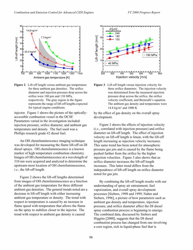
Combustion and Emission Control for Advanced CIDI Engines FY 2000 Progress Report
98
injector. Figure 1 shows the picture of the optically-accessible combustion vessel in the DCSF. Parameters varied in the investigation included: injection pressure, orifice diameter, and ambient gas temperature and density. The fuel used was a Phillips research grade #2 diesel fuel.
An OH chemiluminescence imaging technique was developed for measuring the flame lift-off on DI diesel sprays. OH chemiluminescence is a known marker of high temperature combustion chemistry. Images of OH chemiluminescence at a wavelength of 310 nm were acquired and analyzed to determine the upstream-most location of OH chemiluminescence, i.e., the lift-off length.
Figure 2 shows the lift-off lengths determined from images of OH chemiluminescence as a function of the ambient gas temperature for three different ambient gas densities. The general trends noted are a decrease in lift-off length with either increasing ambient gas temperature or density. The trend with respect to temperature is caused by an increase in flame speed with temperature that allows the flame on the spray to stabilize closer to the injector. The trend with respect to ambient gas density is caused
by the effect of gas density on the overall spray development.
Figure 3 shows the effects of injection velocity (i.e., correlated with injection pressure) and orifice diameter on lift-off length. The effect of injection velocity on lift-off length is linear, with the lift-off length increasing as injection velocity increases. This same trend has been noted for atmospheric pressure gas jets and is caused by the flame being pushed further from the orifice by the higher injection velocities. Figure 3 also shows that as orifice diameter increases the lift-off length increases. This latter trend differs from the independence of lift-off length on orifice diameter noted for gas jets.
By combining the lift-off length results with our understanding of spray air entrainment, fuel vaporization, and overall spray development processes [Siebers, 1998 and 1999; Naber and Siebers, 1996], a picture of how parameters such as ambient gas density and temperature, injection pressure, and orifice diameter affect the DI diesel spray combustion process is beginning to emerge. The combined data, discussed by Siebers and Higgins [2000], suggests that the DI diesel combustion process has changed from one involving a core region, rich in liquid-phase fuel that is
Figure 2. Lift-off length versus ambient gas temperature for three ambient gas densities. The orifice diameter and injection pressure drop across the orifice were 180 µm and 138 MPa, respectively. The gray region in the figure represents the range of lift-off lengths expected for typical engine conditions.
Figure 3. Lift-off length versus injection velocity for three orifice diameters. The injection velocity was determined from the measured injection pressure drop across the orifice, the orifice velocity coefficient, and Bernoulli’s equation. The ambient gas density and temperature were 14.8 kg/m3 and 1000 K

Combustion and Emission Control for Advanced CIDI Engines FY 2000 Progress Report
99
surrounded by combustion, to one in which fuel vaporization is largely completed prior to any combustion (i.e., the current picture for heavy-duty diesels). The changes are due to greater air entrainment upstream of the lift-off length caused by changes in engine design made to meet more stringent emissions regulations over time. These changes include: increased injection pressure, reduced orifice diameter, and reduced in-cylinder gas temperature.
Conclusions
Lift-off lengths determined from images of natural light emission at 310 nm show that as injection pressure (i.e., correlated with injection velocity) or orifice diameter increase, the lift-off length increases, and that as ambient gas density or temperature increase the lift-off length decreases. The results suggest that air entrainment upstream of the lift-off length will vary with conditions thus altering all remaining combustion and emissions formation processes downstream of the flame lift-off location.
An important overall observation was made by considering the lift-off length data in conjunction with liquid-phase fuel penetration and spray development data. The picture developed from the combined data suggests that DI diesel combustion and emission processes have been evolving over time in response to changes made to help meet emissions regulations. The trends observed will ultimately help explain observed effects of engine and injector parameters on soot formation. These trends will also provide robust tests for models being developed for DI diesel combustion and emissions processes.
List of References
1. D. Siebers and B. Higgens, "Effects of Injector Conditions on the Flame Lift-Off Length of DI Diesel Sprays," accepted for Thiesel 2000, Conference on Thermofluidynamic Processes in Diesel Engines, Valencia, Spain, September, 2000.
2. D. Siebers, "Scaling Liquid-Phase Fuel Penetration in Diesel Sprays Based on Mixing-Limited Vaporization," Paper No. 1999-01-0528, SAE International Congress, Detroit, MI, February, 1999.
3. D. Siebers, "Liquid-Phase Fuel Penetration in Diesel Sprays," Transactions of the SAE, Vol. 107, Sec. 3, pp. 1205-1227, 1998.
4. J. Naber and D. Siebers, "Effects of Gas Density and Vaporization on Penetration and Dispersion of Diesel Sprays," Transactions of the SAE, Vol. 105, Sec. 3, pp. 82-111, 1996.
List of Publications
1. D. L. Siebers and B. Higgens, "Effects of Injector Conditions on the Flame Lift-Off Length of DI Diesel Sprays," accepted for Thiesel 2000, Conference on Thermofluidynamic Processes in Diesel Engines, Valencia, Spain, September, 2000.
List of Presentations
1. D. Siebers, "Diesel Spray Lifted Flame Phenomena," Diesel Combustion/Alternative Fuels CRADA Meeting, USCAR, Detroit, MI, June, 2000.
2. D. Siebers, "Diesel Combustion Cross-Cut Research," CIDI Combustion, Emission Control & Fuels R&D Laboratory Merit Review & Peer Evaluation, Argonne National Laboratory, Argonne, IL, May, 2000.
3. D. Siebers, "Diesel Spray Flame Lift-Off Research," OAAT Mid-Year Review, Sandia National Laboratories, Livermore, CA, 2000.
4. D. Siebers, "Progress on the Investigation of Flame Lift-Off in Diesel Sprays," Diesel Combustion/Alternative Fuels CRADA Meeting, Sandia National Laboratories, January, 2000.
5. D. Siebers, "Work in Progress - Diesel Combustion Simulation Facility," Diesel Combustion/Alternative Fuels CRADA Meeting, USCAR, Detroit, MI, October, 1999.
List of Acronyms
DCSF Diesel Combustion Simulation Facility
DI Direct injectionEGR Exhaust Gas Recirculation

Combustion and Emission Control for Advanced CIDI Engines FY 2000 Progress Report
100
D. Microwave-Regenerated Exhaust Particulate Filter Technology
Dick NixdorfIndustrial Ceramic Solutions, LLC1010 Commerce Park Drive, Suite IOak Ridge, TN 37830(865) 482-7552, fax: (865) 482-7505, e-mail: [email protected]
DOE Program Manager: Ken Howden(202) 586-3631, fax: (202) 586-9811, e-mail: [email protected]
DOE Program Manager: Kathi Epping(202) 586-7425, fax: (202) 586-9811, e-mail: [email protected]
DOE Program Manager: Pat Davis(202) 586-8061, fax: ( 202) 586-9811, e-mail: [email protected]
Subcontractors: Microwave Materials Technologies, Inc., Knoxville, TN
This Project addresses the following OTT R&D Plan Barriers and Tasks:
Barriers
B. PM Emissions
Tasks
5c. Microwave Regenerating Diesel Particulate Filter
Objectives
• Follow up the FY 1999 bench scale testing to actual engine test cell work on three types of diesel engines.
• Demonstrate a 75% efficiency in the removal of exhaust particulate matter.
• Demonstrate microwave regeneration efficiency to clean the filter to within 90% of the new filter condition, while the engine is operating at idle speed.
• Provide data on microwave regeneration power requirements and the frequency of regeneration cycles needed during typical diesel engine operating conditions in a light-duty vehicle.
Approach
• Design and fabricate a silicon carbide fiber filter cartridge and microwave regeneration system sized for a PNGV-type diesel engine.
• Test this microwave filter system on a Ford 1.2 liter DIATA diesel engine, an International 7.3 liter diesel engine, and a Volkswagen 1.9 liter diesel engine.
• Analyze the data from the three diesel engine tests to determine particulate removal efficiency, regeneration efficiency, power required for microwave cleaning of the filter cartridge and approximate the cycle time between regenerations.

Combustion and Emission Control for Advanced CIDI Engines FY 2000 Progress Report
101
Accomplishments
• Over the three engine tests, the microwave filter system demonstrated 80% - 95% diesel particulate removal efficiency.
• Microwave regeneration of the filter cartridge, at engine idle operating conditions, demonstrated the ability to return the filter to within 95% - 100% of the "new" filter exhaust flow capacity.
• Calculations based on the data showed that a 1.9 liter Volkswagen engine, operating at cruising speed, would require regeneration approximately every six hours. The regeneration will consume 1.75 kW of power over a period of two minutes.
• The fuel economy penalty assuming regeneration every six hours using 1.75 kW microwave power (2.7 kW engine electrical power) is estimated to be 0.3 percent. No estimate of the impact of increased engine backpressure on fuel economy was made, but it is believed to be minimal due to the low backpressure build-up before regeneration is triggered.
• This microwave regenerated filter system demonstrated potential compliance with the EPA 2007 Tier 2 standards for diesel particulate emissions.
Future Directions
• Durability of the microwave regenerated filter system on an operating vehicle needs to be demonstrated.
• The next step in the development will be the installation and durability testing of the filter system on a vehicle for road testing.
• Future work will include product development of the microwave filter system for a selected car and engine type to demonstrate commercial potential.
Introduction
Current diesel engine particulate filter technologies depend on a catalyst to assist in the regeneration of the filter. Catalyst technology requires an exhaust temperature of approximately 350oC to be effective. Small diesel engines only achieve this exhaust temperature under hard acceleration, with extended high vehicle speeds, or by specific engine and fuel system manipulation techniques. The Microwave Regenerated Particulate Filter can achieve acceptable particulate removal efficiencies and regenerate at the low exhaust temperatures typical of light-duty vehicle urban driving cycle conditions. It may also be a solution to the cold-start HC and CO emissions from diesel and gasoline engines. Microwave heating of catalyst substrates and other diesel soot traps has been tried in previous investigations by others. This technology is unique due to the discovery of a special silicon carbide fiber that efficiently converts microwave
energy to heat energy. A small mass of these fibers can achieve temperatures of 1,200oC in 9 seconds in a standard household microwave oven. ICS has developed a process to incorporate this discovery into a filter cartridge and microwave regeneration system for use in diesel engine exhaust streams, as shown in Figure 1.
Figure 1. Microwave-Regenerated Ceramic Filter System

Combustion and Emission Control for Advanced CIDI Engines FY 2000 Progress Report
102
Approach
After FY 1999 bench testing, the microwave filter system has advanced to tests on commercial diesel engines. The first trial on a diesel engine for the microwave filter system occurred on the 1.2 liter DIATA diesel at the Ford Motor Company’s Scientific Research Laboratory. Figure 2 shows the entry and exit sides of the silicon carbide filter after a filtration cycle on the DIATA engine, where 86% of the diesel particulate was removed. Data were obtained to demonstrate particulate removal efficiency and regeneration efficiency. Since it takes
several hours to load the silicon carbide fiber filter to the regeneration point on these small engines, the filter system was also tested on a production 7.3 liter diesel engine at the University of Tennessee. This larger engine allowed multiple loadings and regeneration cycles of the filter system in a relatively short period of time. That test apparatus, which is shown in Figure 3, provided data on the filter’s soot loading capacity, multiple consecutive regeneration cycle efficiencies, and the microwave regeneration power requirements. A final test to obtain analytical exhaust emissions data was conducted on a 1997 Volkswagen 1.9 liter engine at the Oak Ridge National Laboratory diesel engine test facility. These data provided answers to the program evaluation committee’s questions on particle size distribution of the soot passing through the filter and on the emissions released during microwave regeneration of the filter. A combination of the results of the three diesel engine tests led to the calculation of the time span between regenerations and the fuel penalty for using the microwave regenerated particulate filter technology.
Results
Figure 4 shows the loading and microwave regeneration cycles of the filter system through six successive cycles during the International 7.3 liter diesel engine test. It should be noted that the last two regenerations returned the filter to 100% of its "new" filter condition (measured relative to the pressure drop at 60 cfm flowrate through a new filter). Figure 5, based on the Volkswagen 1.9 liter diesel steady-state testing at ORNL, shows that the microwave-
Figure 2. Entry and Exit Sides of the Filter Cartridge After a 1.2 Liter Diesel Engine Filtration Cycle
Figure 3. Test Apparatus on the Exhaust of a 7.3 Liter Light-Duty Diesel Truck
Figure 4. Pressure Differential across the Filter from Successive Loadings and Regenerations (7.3 Liter Diesel Engine)

Combustion and Emission Control for Advanced CIDI Engines FY 2000 Progress Report
103
regenerated filter is capable of compliance with the EPA Tier 2 particulate emission standards for diesel engines.
Conclusions
The FY 2000 objectives required a 75% reduction in diesel particulate; test results demonstrated an 85%-95% efficiency. The objectives required a 90% regeneration efficiency; test results demonstrated a 95%-100% regeneration efficiency. Most existing exhaust particulate reduction technologies come with a 5% fuel penalty; the microwave filter fuel penalty, as demonstrated in these tests, is 0.3%. Existing catalyst technologies require adjustments to engine operating conditions and/or the addition of fuel additives to regenerate at exhaust temperatures typical of light-duty diesel vehicle operation. The microwave system is independent of those adjustments and/or additives. These three tests on different types of commercial diesel engines demonstrate the ability of the Microwave Regenerated Diesel Particulate Filter System to provide a possible solution to particulate emission control issues for diesel vehicles. The next phase of durability testing, with on-road vehicle demonstrations, can lead to commercial development of the microwave system by the automotive companies.
List of Publications
1. Nixdorf, R. and J. Parks, "Emerging Technologies in Emission Abatement for Diesel Engines", page 10, CADDET Energy Efficiency Newsletter Number 2, June 2000.
List of Presentations
1. Nixdorf, R., "Microwave Regenerated Particulate Filter-Statement of Work", PNGV 4SDI Committee; USCAR; Detroit, MI; March 5, 2000.
2. Nixdorf, R., "Microwave Regenerated Particulate Filter-Project Status", PNGV 4SDI Committee; Detroit Diesel Corporation; Detroit, MI; March 5, 2000.
3. Nixdorf, R., "Microwave Regenerated Particulate Filter", DOE FY 2000 Merit Review and Peer Evaluation National Laboratory, Argonne National Laboratory, March 22, 2000.
List of Acronyms
CO Carbon monoxideDIATA Direct Injection, Aluminum
Through-bolt AssemblyHC HydrocarbonsICS Industrial Ceramic Solutions, LLCPNGV Partnership for a New Generation of
Vehicles
Figure 5. 1.9 Liter Volkswagen Filter Particulate Reduction Results (FTP simulation using steady-state tests)