gas turbine performance by rainer kurz
TRANSCRIPT

8/12/2019 Gas Turbine Performance by Rainer Kurz
http://slidepdf.com/reader/full/gas-turbine-performance-by-rainer-kurz 1/16

8/12/2019 Gas Turbine Performance by Rainer Kurz
http://slidepdf.com/reader/full/gas-turbine-performance-by-rainer-kurz 2/16
THERMODYNAMICS OF THEGAS TURBINE CYCLE (BRAYTON CYCLE)
The conversion of heat released by burning fuel into mechanicalenergy in a gas turbine is achieved by first compressing air in anair compressor, then injecting and burning fuel at (ideally) constantpressure, and then expanding the hot gas in the turbine (BraytonCycle, Figure 3). The turbine provides the necessary power tooperate the compressor. Whatever power is left is used as themechanical output of the engine. This thermodynamic cycle can bedisplayed in an enthalpy-entropy (h-s) diagram (Figure 3). The airis compressed in the engine compressor from state 1 to state 2. Theheat added in the combustor brings the cycle from 2 to 3. The hotgas is then expanded. In a single shaft turbine, the expansion isfrom 3 to 7, while in a two shaft engine, the gas is expanded from3 to 5 in the gas generator turbine and afterwards from 5 to 7 in thepower turbine. The difference between Lines 1-2 and 3-7 describesthe work output of the turbine, i.e., most of the work generated bythe expansion 3-7 is used to provide the work 1-2 to drive the com-pressor.
In a two shaft engine, the distances from 1 to 2 and from 3 to 5must be approximately equal, because the compressor work has tobe provided by the gas generator turbine work output. Line 5-7describes the work output of the power turbine.
Figure 3. Enthalpy-Entropy Diagram for the Brayton Cycle.
For a perfect gas, enthalpy and temperature are related by:
(1)
For the actual process, the enthalpy change∆h for any step canbe related to a temperature rise∆T by a suitable choice of a heatcapacity cp for each of the steps.
The entire process can be described (assuming that the massflow is the same in the entire machine, i.e., neglecting the fuelmass flow and bleed flows, and further assuming that the respec-tive heat capacities cp, cpe, and cp,a are suitable averages):
(2)
In this equation, the first term is the work input by the compreand the third term describes the work extracted by the tursection. The second term is the temperature increase from burthe fuel in the combustor.
For two shaft engines, where the gas generator turbine habalance the power requirements of the compressor, and the upower output is generated by the power turbine, the equation acan be rearranged to find:
(3)
This relationship neglects mechanical losses and the differebetween the gas flow into the compressor and into the turbineto the addition of fuel mass flow. However, the resulting inacccies are small, and do not add to the understanding of the genprinciples.
The compressor and the turbine sections of the engine followthermodynamic relationships between pressure increase and winput, which are for the compressor:
(4)
and the turbine:
(5)
The efficiency of a gas turbine is defined by comparing amount of power contained in the fuel fed into the engine witamount of power yielded. The thermal efficiency is thus:
(6)
and the heat rate is:
(7)
In this paper, T3, turbine inlet temperature (TIT) and turbinrotor inlet temperature (TRIT) will be (loosely) referenced as ftemperatures. The differences, which lie simply in the fact temperatures upstream of the first turbine nozzle (TIT) different from the temperatures downstream of the first no(TRIT) due to the cooling of the nozzles, are not important founderstanding of the topic of this paper. APPENDIX A showexample for a typical gas turbine (GT) cycle.
A QUICK EXCURSION TO AERODYNAMICSAny gas turbine consists of several turbomachines. First, the
an air compressor, and after the combustion has taken place, tis a turbine section. Depending on the design of the gas turbineturbine section may consist either of a gas generator turbine, woperates on the same shaft as the air compressor, and a poturbine, which is on a separate shaft.
The task of the compressor is to bring the inlet air from ambpressure to an elevated pressure. To do this, power is necessi.e., the compressor imparts mechanical power into the air. same relationships that apply to the compressor can also be apto the turbine, except that the turbine extracts work from the fThe transfer of energy is accomplished with rotating rowblades, while the stationary rows allow conversion of kinetic energy (i.e., velocity) into pressure or vice versa.
PROCEEDINGS OF THE THIRTY-FOURTH TURBOMACHINERY SYMPOSIUM • 2005132
∆ ∆h c T p=
( ) ( )( )
− − + − =
− =
c T T c T T P W
c T T E W W
p pe
pe f f
a 2 1 3 7
3 2
/
/
( ) ( )( )
− − = −
− =
c T T c T T
c T T P W
p pe
pe
a 2 1 3 5
5 7 /
( ) P h
W
c
W T T
c
W T p
p p p
c= = − =
−
−
∆2 1
1 2
1
1
1η
γ
γ
( ) P h
W
c
W T T
c
W T
p p
p pt = = − = −
−
∆3 7 3
7
3
1
1
η
γ
γ
η th f f
PW E
=
HRW E
Pth
f f = =
1
η

8/12/2019 Gas Turbine Performance by Rainer Kurz
http://slidepdf.com/reader/full/gas-turbine-performance-by-rainer-kurz 3/16
The fundamental law describing the conversion of mechanicalenergy into pressure in a turbomachine is Euler’s Law. Euler’s lawconnects thermodynamic properties (head) with aerodynamicproperties (i.e., velocities u and c, Figure 4):
(8)
Figure 4. Velocities in a Typical Compressor Stage.
or, for axial flow machines, where the rotational speed u is aboutthe same for inlet and exit of a stage:
(9)
This correlation expresses the fact that the force on the rotatingblade in direction of the rotation is proportional to the deflection of the flow in circumferential direction, i.e.:
(10)
and therefore that power introduced into the flow is the angularvelocityω times the torque generated by Fu:
(11)
A rotating compressor blade passage (stage) imparts energy on thefluid (air) by increasing the fluid’s angular momentum (torque).
Mach Number
The aerodynamic behavior of a turbine or compressor is signif-icantly influenced by the Mach number of the flow. The sameturbine or compressor will show significant differences inoperating range (flow range between stall and choke), pressureratio, and efficiency.
The Mach number increases with increasing flow velocity, anddecreasing temperature T. It also depends on the gas composition,which determines the ratio of specific heatsγ and the gas constantR. To characterize the level of the Mach number of a turboma-chine, the “machine” Mach number Mn is frequently used. Mn doesnot refer to a gas velocity, but to the circumferential speed u of acomponent, for example a blade tip at the diameter D:
(12)
This points to the fact that the Mach number of the componentin question will increase once the speed N is increased. The conse-quences for the operation of the gas turbine are that:• The engine compressor Mach number depends on its speed, theambient temperature, and the relative humidity.• The gas generator turbine Mach number depends on its speed,the firing temperature, and the exhaust gas composition (thus, theload, the fuel, and the relative humidity).
• The power turbine Mach number depends on its speed, thepower turbine inlet temperature, and the exhaust gas composition.
For a given geometry, the reference diameter will always besame. Thus, the machine Mach number can be defined alsterms of a speed, for example, the gas generator speed, and geso-called corrected gas generator speed:
(13)
Even though Ncorr is not dimensionless, it is a convenient way writing the machine Mach number of the component. In
following text, the author will also use this simplified expresN/√T, which is based on the above explanations.In a modern gas turbine, the compressor front stages
transonic, which means that the relative flow velocity into the ris higher than the speed of sound, while the flow velocity leathe rotor is below the speed of sound (Figure 5). Turbine stusually see subsonic inlet velocities, but the velocities withinblade channels can be locally supersonic (Figure 6).
Figure 5. Mach Number Distribution for Typical TransonicCompressor Blades. The Flow Enters at Supersonic Speeds, and Is
Decelerated to Subsonic Speeds at the Exit. (Courtesy Schodl,1977)
Figure 6. Velocity Distribution in a Turbine Nozzle at Different Pressure Ratios. As Soon as the Maximum Local Flow Velocity
Exceeds Mach 1 (At a Pressure Ratio of 1.5 in this Example), the Inlet Flow Can No Longer Be Increased. (Courtesy Kurz, 1991)
Component performance maps show a significant sensitivitchanges in Mach numbers. There is a strong dependency of loenthalpy rise or decrease, and flow range for a given blade rothe characteristic Mach number. Figures 7 and 8, with the c
GAS TURBINE PERFORMANCE 133
∆ h u c u cu u= −2 2 1 1
( )∆ h u c cu u= −2 1
( ) F W c cu u u= −1 2
( ) ( )[ ] P r F r W c c W u c c W hu u u u u= = − = − = ω ω 1 2 1 2 ∆
M u
RT
DN
RT n = =
γ
π
γ
2
N N
T T corr
ref
=
/

8/12/2019 Gas Turbine Performance by Rainer Kurz
http://slidepdf.com/reader/full/gas-turbine-performance-by-rainer-kurz 4/16
pressor maps for typical gas turbine compressors, show in particu-lar the narrowing of the operating range with an increase in Machnumber, which in this case is due to increasing compressor speedNGP(Cohen, et al., 1996).
Figure 7. Typical Compressor Performance Map with Operating Lines for a Single Shaft Engine.
Figure 8. Typical Compressor Performance Map with Operating Lines for a Two Shaft Engine.
For turbine nozzles, one of the effects connected with the Machnumber is the limit to the maximum flow that can pass through anozzle. Beyond a certain pressure ratio, the amount of actual flowQ that can pass through the nozzle can no longer be increased byincreasing the pressure ratio. As demonstrated with Figure 6,which shows the flow velocities in a turbine nozzle for increasingpressure ratios, the velocity or Mach number levels in the nozzlebecome higher and higher, until the speed of sound (= Mach 1) isreached in the throat (for a pressure ratio of 1.7 in the example). Afurther increase of the pressure ratio yields higher velocities down-stream of the throat, but the through-flow (which is proportional tothe velocity at the inlet into the nozzle) can no longer be increased.
Because each gas turbine consists of several aerodynamic com-ponents, the Mach number of each of these components would haveto be kept constant in order to achieve a similar operating conditionfor the overall machine. While the characteristic temperature for theengine compressor is the ambient temperature, the characteristictemperature for the gas generator turbine and the power turbine isthe firing temperature T 3 and the power turbine inlet temperatureT5, respectively. Therefore, if two operating points (op1 and op2)yield the same machine Mach numbers for the gas compressor andthe gas generator turbine, and both operating points are at therespective optimum power turbine speed, then the thermal efficien-cies for both operating points will be the same—as long as secondorder effects, such as Reynolds number variations, effects of gapsand clearances, etc., are not considered.
The requirement to maintain the machine Mach number for thecompressor and gas generator turbine can be expressed by NGPcorr
= constant (which leads to identical Mach numbers for the cpressor):
(14)
and, in order to maintain at the same time the same Mach numfor the gas generator turbine, which rotates at the same speed acompressor, required for the firing temperature is:
(15)
In this case, the fact that the volumetric flow through the tursection is determined by the nozzle geometry also enfor(approximately) identical head and flow coefficients for compsor and turbine.
Therefore, the engine heat rate will remain constant, whileengine power will be changed proportional to the change in density. This approach does not take effects like Reynolds numchanges, changes in clearances with temperature, changes incharacteristics, or the effect of accessory loads into account. approach also finds its limitations in mechanical and temperalimits of an actual engine that restrict actual speeds and firing peratures (Kurz, et al., 1999).
Reynolds NumberWhile the Mach number essentially accounts for the compr
ibility effects of the working gas, the Reynolds number descrthe relative importance of friction effects. In industrial turbines, where neither the working temperatures nor the worpressures change as dramatically as in the operation of aircengines, the effects of changes in the Reynolds number typically not very pronounced. A change in the ambient tempture from 0°F to 100°F changes the Reynolds number of thecompressor stage by about 40 percent. The typical operaReynolds numbers of compressor blades and turbine bladesabove the levels where the effect of changing the Reynolds nuis significant.
Blade Cooling
The temperature in the hot section of gas turbines requirescooling of nozzles and blades (as well as cooling for the combliner). Pressurized air from the engine compressor is brought tblade and nozzle internals. In some designs, steam is used rathan air. There are a number of different ways the coolingaccomplished (Figure 9). The air is pushed through the insidthe blade with the goal of removing as much heat from the bsurface as possible. To this end, ribs are used to increase the bulence and thus the heat transfer (convection cooling), and jeair are blown though small holes to impinge on the blade in(impingement cooling). Another design brings cold air frominside of the blade through small holes to the outer blade surfthis generating a thin layer of cooler air between the blade surand the hot gas (film cooling). The amount of air used impactperformance of the gas turbine, because some (but not all) owork to compress the air is lost if air is used for cooling purpCOMBUSTION
The engine combustor is the place where fuel is injec(through fuel injectors) into the air previously compressed inengine compressor. The released fuel energy causes the tempture to rise:
(16)
The heat capacity ˜cpe in the equation above is a suitable averagheat capacity. Modern combustors convert the energy stored i
PROCEEDINGS OF THE THIRTY-FOURTH TURBOMACHINERY SYMPOSIUM • 2005134
N
T
N
T
GP op
op
GP op
op
,
,
,
,
1
1 1
2
1 2
=
T
T
T
T op
op
op
op
3 1
1 1
3 2
1 2
,
,
,
,
=
( )~ /c T T E W W pe f f 3 2− =
8/12/2019 Gas Turbine Performance by Rainer Kurz
http://slidepdf.com/reader/full/gas-turbine-performance-by-rainer-kurz 5/16
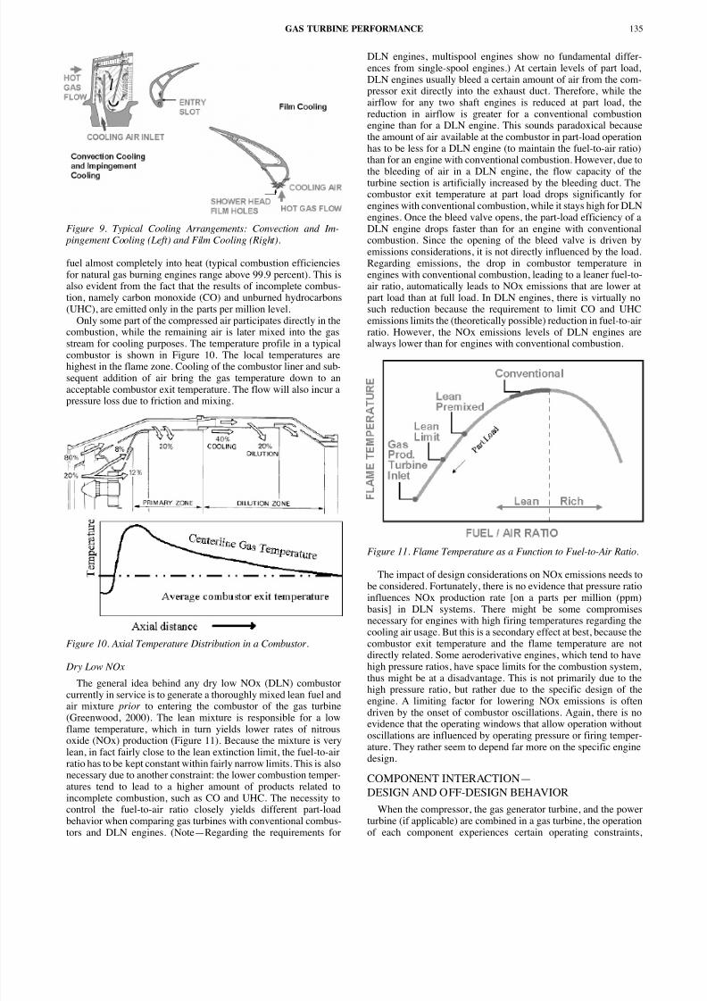
Figure 9. Typical Cooling Arrangements: Convection and Im- pingement Cooling (Left) and Film Cooling (Right).
fuel almost completely into heat (typical combustion efficienciesfor natural gas burning engines range above 99.9 percent). This isalso evident from the fact that the results of incomplete combus-tion, namely carbon monoxide (CO) and unburned hydrocarbons(UHC), are emitted only in the parts per million level.
Only some part of the compressed air participates directly in thecombustion, while the remaining air is later mixed into the gasstream for cooling purposes. The temperature profile in a typicalcombustor is shown in Figure 10. The local temperatures arehighest in the flame zone. Cooling of the combustor liner and sub-sequent addition of air bring the gas temperature down to anacceptable combustor exit temperature. The flow will also incur apressure loss due to friction and mixing.
Figure 10. Axial Temperature Distribution in a Combustor.
Dry Low NOx
The general idea behind any dry low NOx (DLN) combustorcurrently in service is to generate a thoroughly mixed lean fuel andair mixture prior to entering the combustor of the gas turbine(Greenwood, 2000). The lean mixture is responsible for a lowflame temperature, which in turn yields lower rates of nitrousoxide (NOx) production (Figure 11). Because the mixture is verylean, in fact fairly close to the lean extinction limit, the fuel-to-airratio has to be kept constant within fairly narrow limits. This is alsonecessary due to another constraint: the lower combustion temper-atures tend to lead to a higher amount of products related toincomplete combustion, such as CO and UHC. The necessity tocontrol the fuel-to-air ratio closely yields different part-loadbehavior when comparing gas turbines with conventional combus-tors and DLN engines. (Note—Regarding the requirements for
DLN engines, multispool engines show no fundamental diences from single-spool engines.) At certain levels of part lDLN engines usually bleed a certain amount of air from the cpressor exit directly into the exhaust duct. Therefore, whileairflow for any two shaft engines is reduced at part load, reduction in airflow is greater for a conventional combusengine than for a DLN engine. This sounds paradoxical becthe amount of air available at the combustor in part-load operahas to be less for a DLN engine (to maintain the fuel-to-air rathan for an engine with conventional combustion. However, d
the bleeding of air in a DLN engine, the flow capacity of turbine section is artificially increased by the bleeding duct. combustor exit temperature at part load drops significantlyengines with conventional combustion, while it stays high for engines. Once the bleed valve opens, the part-load efficiencyDLN engine drops faster than for an engine with conventicombustion. Since the opening of the bleed valve is drivenemissions considerations, it is not directly influenced by the lRegarding emissions, the drop in combustor temperatureengines with conventional combustion, leading to a leaner fueair ratio, automatically leads to NOx emissions that are lowepart load than at full load. In DLN engines, there is virtuallysuch reduction because the requirement to limit CO and Uemissions limits the (theoretically possible) reduction in fuel-tratio. However, the NOx emissions levels of DLN enginesalways lower than for engines with conventional combustion
Figure 11. Flame Temperature as a Function to Fuel-to-Air Ratio.
The impact of design considerations on NOx emissions neebe considered. Fortunately, there is no evidence that pressure influences NOx production rate [on a parts per million (pbasis] in DLN systems. There might be some compromnecessary for engines with high firing temperatures regardingcooling air usage. But this is a secondary effect at best, becauscombustor exit temperature and the flame temperature aredirectly related. Some aeroderivative engines, which tend to hhigh pressure ratios, have space limits for the combustion systhus might be at a disadvantage. This is not primarily due tohigh pressure ratio, but rather due to the specific design ofengine. A limiting factor for lowering NOx emissions is odriven by the onset of combustor oscillations. Again, there ievidence that the operating windows that allow operation witoscillations are influenced by operating pressure or firing temature. They rather seem to depend far more on the specific endesign.
COMPONENT INTERACTION—DESIGN AND OFF-DESIGN BEHAVIOR
When the compressor, the gas generator turbine, and the poturbine (if applicable) are combined in a gas turbine, the operaof each component experiences certain operating constra
GAS TURBINE PERFORMANCE 135

8/12/2019 Gas Turbine Performance by Rainer Kurz
http://slidepdf.com/reader/full/gas-turbine-performance-by-rainer-kurz 6/16
which are caused by the interaction between the components(Figure 12).
Figure 12. Interaction Between the Gas Turbine Components.
For example, the engine compressor will compress a certainmass flow, which in turn dictates the compressor dischargepressure necessary to force the mass flow through the turbinesection. On the other hand, the gas generator turbine has to producesufficient power to drive the generator. The firing temperatureinfluences the power that the turbines can produce, but it alsoimpacts the discharge pressure necessary from the compressor.
The components are designed to work together at their highestefficiencies at a design point, but the operation of the componentsat any other than the design point must also be considered. Theconstraints and requirements are different for single shaft and twoshaft engines, hence they are treated separately. In the followingsection, the author will look into the interaction between the enginecomponents, because it is this interaction that generates the typicalbehavior of gas turbines.
Single Shaft Engines
A single shaft engine consists of an air compressor, a combustor,and a turbine. The air compressor generates air at a high pressure,which is fed into the combustor where the fuel is burned. The com-bustion products and excess air leave the combustor at highpressure and high temperature. This gas is expanded in the gasgenerator turbine, which provides the power to turn the air com-pressor. The excess power is used to drive the load. Most singleshaft turbines are used to drive electric generators at constantspeeds. The author will not consider the rare case of single shaftturbines driving mechanical loads at varying speeds. The operationof the components requires the following compatibility conditions:• Compressor speed = gas generator turbine speed• Mass flow through turbine = mass flow through compressorbleed flows + fuel mass flow• Compressor power < turbine powerTypical compressor and turbine maps are shown in Figures 7 and8, respectively.
The fact that the gas turbine operates at constant speed meansany operating point of the engine compressor (for given ambientconditions) lies on a single speed line. Load increases are initiatedby increasing the fuel flow, which in turn increases the firing tem-perature. Due to the fact that the first turbine nozzle is usuallychoked, the compressor operating point moves to a higher pressureratio to compensate for the reduced density (from the higher firingtemperature). The possible operating points of the compressordepending on the load running are also shown in the compressormaps (Figures 7 and 8).
In the case of the single shaft engine driving a generator,reduction in output power results in only minute changes in com-pressor mass flow as well as some reduction in compressorpressure ratio. A single shaft engine has no unique matching tem-perature. Used as a generator drive, it will operate at a single speedand can be temperature topped at any ambient temperature as longas the load is large enough.
Two Shaft Engines
A two shaft gas turbine (Figure 2) consists of an air comprea combustor, a gas generator turbine, and a power turbine. [NoSome engines are configured as multispool engines. In this cthe gas generator has a low-pressure compressor driven by a pressure turbine and a high-pressure compressor driven bhigh-pressure turbine. For this configuration, the shaft connethe low-pressure (LP) compressor and turbine rotates insideshaft connecting the high-pressure (HP) compressor and turbingeneral, all the operating characteristics described above aapply to these engines.] The air compressor generates air at a pressure, which is fed into to the combustor where the fueburned. The combustion products and excess air leave combustor at high pressure and high temperature. This gaexpanded in the gas generator turbine, which has the sole tasproviding power to turn the air compressor. After leaving thegenerator turbine, the gas still has a high pressure and a high perature. It is now further expanded in the power turbine. power turbine is connected to the driven equipment. It musnoted at this point that the power turbine (together with the drequipment) can and will run at a speed that is independent ospeed of the gas generator portion of the gas turbine (i.e., thcompressor and the gas generator turbine).
The gas generator is controlled by the amount of fuel thasupplied to the combustor. Its two operating constraints are
firing temperature and the maximum gas generator speed (on sengines, torque limits may also constrain the operation at ambient temperatures). If the fuel flow is increased, both fitemperature and gas generator speed increase, until one of theoperating limits is reached. Variable stator vanes at the engcompressor are frequently used, however, not for the purposcontrolling the airflow, but rather to optimize the gas produspeed. In two shaft engines, the airflow is controlled by the capacities of the gas generator turbine and power turbine nozz
Increasing the speed and temperature of the gas generaprovides the power turbine with gas at a higher energy (i.e., hipressure, higher temperature, and higher mass flow), which althe power turbine to produce more power. If the power suppliethe power turbine is greater than the power absorbed by the lthe power turbine together with the driven compressor will ac
erate until equilibrium is reached.The operation of the components requires the following cpatibility conditions:• Compressor speed = gas generator turbine speed• Mass flow through turbine = mass flow through compressobleed flows + fuel mass flow• Compressor power = gas generator turbine power (mechani-cal losses)• The subsequent free power turbine adds the requirement thapressure after the gas producer (GP) turbine has to be high ento force the flow through the power turbine.
Typical compressor and turbine maps are shown in Figurand 13, respectively. The gas generator for a two shaft engadapts to different load requirements (and, accordingly, diffefuel flow) by changing both speed and firing temperature. Nthat the compressor operating points are very different betwesingle shaft and a two shaft engine.
Two shaft engines operate with the gas generator turbine andpower turbine in series. The power turbine pressure ratio p5/pa isthus related to the compressor pressure ratio p2/pa by the identity:
(17)
The pressure drop in the gas generator turbine p5/p3 and thepressure increase in the compressor p2/pa are related insofar as the
PROCEEDINGS OF THE THIRTY-FOURTH TURBOMACHINERY SYMPOSIUM • 2005136
p
p
p
p
p
p
p
pa a
5 2 3
2
5
3
=

8/12/2019 Gas Turbine Performance by Rainer Kurz
http://slidepdf.com/reader/full/gas-turbine-performance-by-rainer-kurz 7/16
Figure 13. Schematic Turbine Performance Map for Two Turbines(Gas Generator and Power Turbine) in Series.
gas generator turbine has to provide enough power to drive thecompressor.
The maximum possible pressure ratio p 5/pa is controlled by theflow capacity Q 5 of the power turbine. In particular if the powerturbine is choked, it will cause the gas generator turbine tooperate at one fixed point (Figure 13). In many cases, both the gasgenerator turbine first-stage nozzle and the power turbine nozzleoperate at or near choked flow conditions. In this case, the actual
flow Q 3 through the gas generator turbine nozzle is practicallyconstant. The mass flow is then only dependent on the combustorexit pressure p 3, the firing temperature T 3, the gas composition(which determines γ and thus the volume increase during theexpansion), and the geometry of the nozzle, which determines thethrough-flow area (in reality, it is determined by the criticalnozzle area, the clearance area, and the effective bleed valvearea).
The above relationship has the following consequences:
• Increasing the firing temperature (without changing speed orgeometry) will lead to a lower mass flow.
• Increasing the gas generator speed, thus increasing p2 and p3,will allow for a larger mass flow.
• Pressure ratio, speed, and firing temperature are all related, andcannot be changed independently of each other. The turbinegeometry determines both flow capacities Q3 and Q5, as well as thegas generator turbine efficiency. The compressor geometry andspeed set the airflow.
• With variable inlet guide vanes (IGVs) the airflow can be alteredwithout changing the gas generator speed, thus also setting a newT3 and a different compressor pressure ratio p2/p1. The relationshipbetween p2/p1 and T3 remains, however, unchanged. The turbineflow capacities alone determine the gas generator match, not theIGV setting. Closing the IGVs will raise the speed of a temperaturetopped gas generator, but since the temperature remains constant,the airflow tends to remain unchanged (because the flow throughthe gas generator turbine nozzle Q3 remains constant). If, however,η ggt increases due to the change in speed, T3 has to drop, leadingto an increase in compressor mass flow. The gas generator pumpsmore airflow with the IGV closed and the higher speed than withthe IGV open and the lower speed. The IGVs thus allow trimmingof the engine such that the rated T3 is always reached at fullcorrected gas generator speed (NGP). Therefore, at high ambienttemperatures, when the gas generator would normally slow down,IGVs can be used to keep the speed at a higher level, thus avoidingefficiency penalties in the gas generator turbine. Reducing the netpower output in a two shaft engine involves a reduction in com-pressor speed and hence in air flow, pressure ratio, and temperaturerise. From a comparison of the maps (Figure 14) one can see thatthe compressor in a two shaft engine operates for most of the loadpoints close to its best efficiency.
“A”
“B”
“C”
Figure 14. Gas Turbine Performance Maps—A and B: Two Shaft;C: Single Shaft.
Two shaft engines have a power turbine where the shaft ismechanically coupled with the gas generator shaft. These comnents need to be “matched,” such that the overall performancthe gas turbine is optimized for a defined operating ambient tperature. The speed of the gas generator is therefore not contrby the speed of the driven equipment (such as in single sgenerator set applications). The gas generator speed only depon the load applied to the engine. If the power turbine outputto be increased, the fuel control valve allows more fuel to entecombustor. This will lead to an increase both in gas generspeed and in firing temperature, thus making more power avaiat the power turbine.
The setting of the flow capacity of the power turbine obviously a great influence on the possible operating points ogas generator. For a high resistance of the power turbine (i.e.,mass flow W for a given p5/p1), the gas generator reaches itslimiting firing temperature at lower ambient temperatures twith a low resistance of the power turbine. By altering the exit
GAS TURBINE PERFORMANCE 137

8/12/2019 Gas Turbine Performance by Rainer Kurz
http://slidepdf.com/reader/full/gas-turbine-performance-by-rainer-kurz 8/16
angle of the first stage power turbine nozzle the required pressureratio for a certain flow can be modified (i.e., the flow capacity).This effect is used to match the power turbine with the gasgenerator for different ambient temperatures.
Due to mechanical constraints, both the gas generator speed andthe firing temperature have upper limits that cannot be exceededwithout damaging the engine or reducing its life. Depending on:• The ambient temperature,• The accessory load, and
• The engine geometry (in particular the first power turbinenozzle),the engine will reach one of the two limits first. At ambient tem-peratures below the match temperature, the engine will beoperating at its maximum gas generator speed, but below itsmaximum firing temperature (speed topping). At ambient temper-atures above the match temperature, the engine will operate at itsmaximum firing temperature, but not at its maximum gas generatorspeed (temperature topping). The match temperature is thus theambient temperature at which the engine reaches both limits at thesame time (Figure 14a and b).
Because the first power turbine nozzle determines the amount of pressure ratio needed by the power turbine to allow a certain gasflow it also determines the available pressure ratio for the gasgenerator turbine. If the pressure ratio available for the gasgenerator does not allow balancing of the power requirement of theengine compressor (refer to the enthalpy-entropy diagram), the gasgenerator will have to slow down, thus reducing the gas flowthrough the power turbine. This will reduce the pressure rationecessary over the power turbine, thus leaving more head for thegas generator to satisfy the compressor power requirements.
Some effects can cause the gas turbine to exhibit an alteredmatch temperature. Gas fuel with a low heating value or waterinjection increase the mass flow through the turbine relative to thecompressor mass flow. The temperature topping will thus beshifted to higher ambient temperatures. Dual fuel engines that arematched on gas will top early on liquid fuel. This is caused by thechange in the thermodynamic properties of the combustion productdue to the different carbon to hydrogen ratio of the fuels. Thematching equations indicate that a reduction in compressor effi-
ciency (due to fouling, inlet distortions) or turbine efficiency(increased tip clearance, excessive internal leaks, corrosion) willalso cause early topping. Accessory loads also have the effect of leading to earlier topping.
Single Shaft Versus Two Shaft Engines
The choice of whether to use a single shaft or two shaft powerplant is largely determined by the characteristics of the driven load.If the load speed is constant, as in the case of an electric generator,a single shaft unit is often specified; an engine specificallydesigned for electric power generation would make use of a singleshaft configuration. An alternative, however, is the use of a twoshaft engine. If the load needs to be driven with varying speeds(compressors, pumps), two shaft engines are advantageous.
The two types have different characteristics regarding the supplyof exhaust heat to a cogeneration or combined cycle plant,primarily due to the differences in exhaust flow as load is reduced;the essentially constant air flow and compressor power in a singleshaft unit results in a larger decrease of exhaust temperature for agiven reduction in power, which might necessitate the burning of supplementary fuel in the waste heat boiler under operating condi-tions where it would be unnecessary with a two shaft. In bothcases, the exhaust temperature may be increased by the use of variable inlet guide vanes. Cogeneration systems have been suc-cessfully built using both single shaft and two shaft units.
The torque characteristics are very different, and the variation of torque with output speed at a given power may well determine theengine’s suitability for certain applications. The compressor of a
single shaft engine is constrained to turn at some multiple ofload speed, fixed by the transmission gear ratio, so that a reducin load speed implies a reduction in compressor speed. This rein a reduction in mass flow hence of output of torque. This tyturbine is only of limited use for mechanical drive purposes.two shaft unit, having a free power turbine, however, has a favorable torque characteristic. For a constant fuel flow, constant gas generator speed, the free power turbine can prorelatively constant power for a wide speed range. This is due tfact that the compressor can supply an essentially constant flo
a given compressor speed, irrespective of the free turbine spAlso, at fixed gas generator operating conditions, reductiooutput speed results in an increase in torque. It is quite possibobtain a stall torque of twice the torque delivered at full speed
The actual range of speed over which the torque conversioefficient depends on the efficiency characteristic of the poturbine. The typical turbine efficiency characteristic shownFigure 14 suggests that the efficiency penalty will not be grethan about 5 or 6 percent over a speed range from half to full sp
Load
Any gas turbine will experience a reduced efficiency at part (Figure 15). The reduction in efficiency with part load differs design to design. In particular, DLN engines show different pload efficiencies than their conventional combustion counterp
The necessity to control the fuel to air ratio closely yields diffepart load behavior when comparing gas turbines with DLN cbustors and with conventional combustors. A typical waycontrolling these engines is by controlling the airflow intocombustor, thus keeping the combustor primary zone temperwithin narrow limits. The part load behavior of single shafttwo shaft, standard combustion, and dry low Nox concepts aredamentally different. This is both due to the different aerodynconfiguration and the requirements of keeping the fuel to air within a narrow window for DLN engines.
Figure 15. Thermal Efficiency of Typical Industrial Gas Turbinesas a Function of Load.
To operate the engine at part load, the fuel flow is adjusted, usome control parameter (for example the flow through the drcompressor, or a certain kW value for a generator) is satisfOther adjustments, such as guide vane settings or bypassing cbustion air may be necessary.
For a single shaft engine, which has to operate at constantgenerator speed (to keep the generator frequency constant),means that the firing temperature will be changed with loadgovernor will keep the speed constant and will increase the flow with increasing load, thus increasing the firing temperauntil the control limit is reached. Due to the constant speed,airflow through the engine will not vary greatly between full and part load. This means that the fuel to air ratio drops signcantly at part load and the combustor exit temperature drsignificantly from full load to part load. Therefore, most sishaft dry low NOx engines use variable stator vanes on the en
PROCEEDINGS OF THE THIRTY-FOURTH TURBOMACHINERY SYMPOSIUM • 2005138

8/12/2019 Gas Turbine Performance by Rainer Kurz
http://slidepdf.com/reader/full/gas-turbine-performance-by-rainer-kurz 9/16
compressor to vary the airflow, and thus keep the fuel to air ratiorelatively constant.
For a given mass flow, any increase in firing temperature wouldincrease the volume flow through the turbine section. Therefore thepressure supplied from the compressor has to be increased,because the turbine nozzle is at or near choked conditions. Sincethe compressor also operates at constant speed, the result is areduction of mass flow until equilibrium is reached. A typical per-formance map for a single shaft engine shows this increase incompressor discharge pressure at increased load. If the engine is
equipped with variable inlet guide vanes (VIGVs) to keep the fuelto air ratio in the combustor constant, a reduction in load willrequire a closing of the VIGVs to reduce the airflow. Closing theVIGVs also reduces the pressure ratio of the compressor atconstant speed.
For single shaft engines as described above, the part load effi-ciencies of gas turbines with DLN combustion and conventionalcombustion are very similar. The need to bleed combustion air fortwo shaft engines typically leads to a lower part load efficiency forengines equipped with DLN combustors.
For a two shaft engine, both gas generator speed and firing tem-perature change with load. An increase in load at the power turbinewill cause the fuel flow to increase. Because the gas generator isnot mechanically coupled with the power turbine, it will acceler-ate, thus increasing airflow, compressor discharge pressure, andmass flow. The increase in gas generator speed means that thecompressor now operates at a higher Mach number. At the sametime the increased fuel flow will also increase the firing tempera-ture. The relative increase is governed by the fact that the powerturbine requires a certain pressure ratio to allow a given amount of airflow pass. This forces an equilibrium where the followingrequirements have to be met:• The compressor power equals gas generator turbine power. Thisdetermines the available pressure upstream of the power turbine(PT).• The available pressure ratio at the power turbine is sufficient toallow the airflow to be forced through the power turbine.
Depending on the ambient temperature relative to the enginematch temperature, the fuel flow into the engine will either belimited by reaching the maximum firing temperature or themaximum gas generator speed. The ambient temperature, whereboth control limits are reached at the same time, is called enginematch temperature.
Variable stator vanes at the engine compressor are frequentlyused, however, not for the purpose of controlling the airflow. Thisis due to the fact that in two shaft engines, the airflow is controlledby the flow capacities of the gas generator turbine and powerturbine nozzles. To control the fuel to air ratio in the combustor,another control feature has to be added for two shaft engines withdry low Nox combustors. Usually, a certain amount of air is bledfrom the compressor exit directly into the exhaust duct. This leadsto the fact that while the airflow for two shaft engines is reduced atpart load, the reduction in airflow is larger for an engine with astandard combustion system. Like in single shaft engines, thecombustor exit temperature at part load drops significantly forengines with standard combustion, while it stays relatively high forDLN engines. The drop in combustor temperature in engines withstandard combustion, which indicates the leaner fuel to air ratio,automatically leads to NOx emissions that are lower at part loadthan at full load. In DLN engines, there is virtually no suchreduction, because the requirement to l imit CO and UHC emissionslimits the (theoretically possible) reduction in fuel to air ratio.
Power Turbine Speed
For any operating condition of the gas generator, there is anoptimum power turbine speed at which the power turbine operatesat its highest efficiency, and thus produces the highest amount of
power for a given gas generator operating point. Aerodynamithis optimum point is characterized by a certain ratio of actual Q5 over roating speed NPT. The volumetric flow depends on thambient temperature and the load. This explains why the optimpower turbine speed is a function of ambient temperature and
If the power turbine does not operate at the optimum poturbine speed, the power output and the efficiency of the poturbine will be lower (Figure 14b). The impact of changingpower turbine speed is easily described by:
(18)
This equation can be derived from basic relationships (BrunKurz, 2001) and is pretty accurate for any arbitrary power tur
When using this relationship, it must be considered that optimum power turbine speed (Npt,opt) depends on the gasgenerator load and the ambient temperature (Kurz and B2001). In general, the optimum power turbine speed is reduceincreasing ambient temperatures and lower load (Figure 14b)heat rate becomes for a constant gas generator operating poin
(19)
Off-optimum speed of the power turbine reduces the efficieand the ability to extract head from the flow. Even if NGG(and thefuel flow) does not change, the amount of power that is prodby the PT is reduced. Also, because of the unchanged fuel flowengine heat rate increases and the exhaust temperature increaccordingly. Theoretically, any engine would reach its maximexhaust temperature at high ambient, full load, and locked PT
Another interesting result of the above is the torque behaviothe power turbine, considering that torque is power dividedspeed:
(20)
The torque is thus a linear function of the speed, with maximum torque at the lowest speed. This explains one of the attractions of a free power turbine: to provide the necessary toto start the driven equipment is usually not difficult (compareelectric motor drives or reciprocating engines) because the higtorque is already available at low speeds of the power turbine
Influence of Emission Control Technologies
All emission control technologies that use lean-premix comtion require a precise management of the fuel to air ratio inprimary zone of the combustor (i.e. where the initial combustakes place) as well as a precise distribution of combustor lcooling and dilution flows. Deviations in these areas can leaincreased NOx production, higher CO or UHC levels, or flam(Greenwood, 2000).
Lean-premix combustion achieves reduction in NOx emissby lowering the flame temperature. The flame temperature is dmined by the fuel to air ratio in the combustion zone.stoichiometric fuel to air ratio (such as in conventional comtors) leads to high flame temperatures, while a lean fuel to air can lower the flame temperature significantly. However, a leanto air mixture also means that the combustor is operating closthe lean flameout limit.
Any part load operation will cause reduction of fuel to air rbecause the reduction in air flow is smaller than the reductiofuel flow. Several different approaches to control the fuel toratio are possible to avoid flameout at part load or transient sitions, for example:
GAS TURBINE PERFORMANCE 139
P P
N N
N N opt
PT
PT opt
PT
PT opt = −
2
2
, ,
HR
HR
P
Popt
opt =
τ
τ opt
PT
PT opt
N
N = −
2
,

8/12/2019 Gas Turbine Performance by Rainer Kurz
http://slidepdf.com/reader/full/gas-turbine-performance-by-rainer-kurz 10/16
• Bleeding air overboard,• Using variable inlet guide vanes, and• Managing the ratio between fuel burned in lean premix modeand in a diffusion flame,to name a few. Obviously, all these approaches can have an effecton the part load performance characteristics of the gas turbine.
Variable Inlet and Stator Vanes
Many modern gas turbines use variable inlet guide vanes andvariable stator vanes in the engine compressor. Adjustable vanesallow altering of the stage characteristics of compressor stages(refer to the explanation on Euler equations in the previous section,“A QUICK EXCURSION TO AERODYNAMICS”) because theychange the head making capability of the stage by increasing orreducing the preswirl contribution. This means that for a prescribedpressure ratio they also alter the flow through the compressor. It istherefore possible to change the flow through the compressorwithout altering its speed. There are three important applications:1. During startup of the engine it is possible to keep the compres-sor from operating in surge.2. The airflow can be controlled to maintain a constant fuel to airratio in the combustor for dry low NOx applications on single shaftmachines.3. Two shaft engines can be kept from dropping in gas generatorspeed at ambient temperatures higher than the match temperature,i.e., the gas generator turbine will continue to operate at its highestefficiency.
Accessory Loads
Accessory loads are due to mechanically driven lube oil orhydraulic pumps. While the accessory load can be treated fairlyeasily in a single shaft engine—its power requirement is subtractedfrom the gross engine output—this is somewhat more complicatedin a two shaft machine.
In a two shaft gas turbine, the accessory load is typically takenfrom the gas generator. In order to satisfy the equilibrium condi-tions the gas generator will have to run hotter than without the load.This could lead to more power output at conditions that are not tem-perature limited. When the firing temperature is limited (i.e., forambient temperatures above the match point), the power output willfall off more rapidly than without the load. That means that anaccessory load of 50 hp may lead to power losses at the powerturbine of 100 or more hp at higher ambient temperatures. The heatrate will increase due to accessory loads at all ambient tempera-tures. The net effect of accessory loads can also be described as amove of the match point to lower ambient temperatures.
Control Temperature
One of the two operating limits of a gas turbine is the turbinerotor inlet temperature (TRIT or T3). Unfortunately, it is notpossible to measure this temperature directly—a temperatureprobe would only last for a few hours at temperatures that high.Therefore, the inlet temperature into the power turbine (T
5) is
measured instead. The ratio between T3 and T5 is determinedduring the factory test, where T5 is measured and T3 is determinedfrom a thermodynamic energy balance. This energy balancerequires the accurate determination of output power and air flow,and can therefore be performed best during the factory test.
It must be noted that both T3 and T5 are circumferentially andradially very nonuniformly distributed in the reference planes (i.e.,at the combustor exit, at the rotor inlet, at the power turbine inlet).Performance calculations use a thermodynamic average tempera-ture. This is not exactly the temperature one would measure as theaverage of a number of circumferentially distributed temperatureprobes.
Rather than controlling T3 the control system limits engine operations to the T5 that corresponds to the rated T3. However, the ratiobetween T3 and T5 is not always constant, but varies with thambient temperature; the ratio T3/T5 is reduced at higher ambienttemperatures. Modern control algorithms can take this iaccount.
Engines can also be controlled by their exhaust tempera(T7). For single shaft engines, measuring T7 or T5 are equivalentchoices. For two shaft engines, measuring T7 instead of T5 adds thecomplication that the T7 control temperature additionally depend
on the power turbine speed, while the relationship between T3 andT5 does not depend on the power turbine speed.
INFLUENCE OF AMBIENT CONDITIONS Ambient Temperature
Changes in ambient temperature have an impact on full-lpower and heat rate, but also on part-load performance optimum power turbine speed (Figure 14). Manufacturers typiprovide performance maps that describe these relationshipsInternational Organization for Standardization (ISO) conditiThese curves are the result of the interaction between the varrotating components and the control system. This is particultrue for DLN engines.
If the ambient temperature changes, the engine is subject tofollowing effects:
• The air density changes. Increased ambient temperature lowthe density of the inlet air, thus reducing the mass flow througturbine, and therefore reduces the power output (which is protional to the mass flow) even further. At constant speed, whervolume flow remains approximately constant, the mass flowincrease with decreasing temperature and will decrease wincreasing temperature.• The pressure ratio of the compressor at constant speed gsmaller with increasing temperature. This can be determined fa Mollier diagram, showing that the higher the inlet temperatuthe more work (or head) is required to achieve a certain presrise. The increased work has to be provided by the gas geneturbine, and is thus lost for the power turbine, as can be seen ienthalpy-entropy diagram.
At the same time NGgcorr(i.e., the machine Mach number) aconstant speed is reduced at higher ambient temperature. explained previously, the inlet Mach number of the engine cpressor will increase for a given speed, if the ambient temperais reduced. The gas generator Mach number will increasereduced firing temperature at constant gas generator speed.
The enthalpy-entropy diagram (Figure 3) describes the Bracycle for a two shaft gas turbine. Lines 1-2 and 3-4 mustapproximately equal, because the compressor work has toprovided by the gas generator turbine work output. Line describes the work output of the power turbine. At higher amtemperatures, the starting point 1 moves to a higher temperaBecause the head produced by the compressor is proportionthe speed squared, it will not change if the speed remains the sHowever, the pressure ratio produced, and thus the dischapressure, will be lower than before. Looking at the combusprocess 2-3, with a higher compressor discharge temperatureconsidering that the firing temperature T3 is limited, one sees thatless heat input is possible, i.e., less fuel will be consumed. expansion process has, due to the lower p2 = p3, less pressure ratioavailable, or a larger part of the available expansion work is bused up in the gas generator turbine, leaving less work availablthe power turbine.
On two shaft engines, a reduction in gas generator speed ocat high ambient temperatures. This is due to the fact that the elibrium condition between the power requirement of compressor (which increases at high ambient temperatures ipressure ratio must be maintained) and the power productio
PROCEEDINGS OF THE THIRTY-FOURTH TURBOMACHINERY SYMPOSIUM • 2005140

8/12/2019 Gas Turbine Performance by Rainer Kurz
http://slidepdf.com/reader/full/gas-turbine-performance-by-rainer-kurz 11/16
the gas generator turbine (which is not directly influenced by theambient temperature as long as compressor discharge pressure andfiring temperature remain) will be satisfied at a lower speed.
The lower speed often leads to a reduction of turbine efficiency.The inlet volumetric flow into the gas generator turbine is deter-mined by the first stage turbine nozzle, and the Q3/NGGratio (i.e.,the operating point of the gas generator turbine) therefore movesaway from the optimum. Variable compressor guide vanes allowkeeping the gas generator speed constant at higher ambient tem-peratures, thus avoiding efficiency penalties.
In a single shaft, constant speed gas turbine one would see aconstant head (because the head stays roughly constant for aconstant compressor speed), and thus a reduced pressure ratio.Because the flow capacity of the turbine section determines thepressure-flow-firing temperature relationship, an equilibrium willbe found at a lower flow and a lower pressure ratio, thus a reducedpower output.• The compressor discharge temperature at constant speedincreases with increasing temperature. Thus, the amount of heatthat can be added to the gas at a given maximum firing tempera-ture is reduced.• The relevant Reynolds number changes.
At full load, single shaft engines will run at temperature toppingat all ambient temperatures, while two shaft engines will run either
at temperature topping (at ambient temperatures higher than thematch temperature) or at speed topping (at ambient temperatureslower than the match temperature). At speed topping, the enginewill not reach its full firing temperature, while at temperaturetopping, the engine will not reach its maximum speed.
The net effect of higher ambient temperatures is an increase inheat rate and a reduction in power. The impact of ambient temper-ature is usually less pronounced for the heat rate than for the poweroutput, because changes in the ambient temperature impact less thecomponent efficiencies than the overall cycle output.
Inlet and Exhaust Pressure Losses
Any gas turbine needs an inlet and exhaust system to operate. Theinlet system consists of one or several filtration systems, a silencer,ducting, and possibly deicing, fogging, evaporative cooling, and
other systems. The exhaust system may include a silencer, ducting,and waste heat recovery systems. All these systems will causepressure drops, i.e., the engine will actually see an inlet pressure thatis lower than ambient pressure and will exhaust against a pressurethat is higher than the ambient pressure. These inevitable pressurelosses in the inlet and exhaust system cause a reduction in power andcycle efficiency of the engine. The reduction in power, compared toan engine at ISO conditions, can be described by simple correctioncurves, which are usually supplied by the manufacturer. The onesshown in Figure 16 describe the power reduction for every inch (ormillimeter) of water pressure loss. These curves can be easilyapproximated by second order polynomials. The impact on heat rateis easily calculated by taking the fuel flow from ISO conditions anddividing it by the reduced power.
Figure 16. Correction Factors for Inlet Losses, Exhaust Losses,and Site Elevation.
Ambient Pressure
The impact of operating the engine at lower ambient press(for example, due to site elevation or simply due to changatmospheric conditions) is that of a reduced air density (Figureand 17). The engine, thus, sees a lower mass flow (while the vmetric flow is unchanged). The changed density only impactpower output, but not the efficiency of the engine. However, iengine drives accessory equipment through the gas generatoris no longer true because the ratio between gas generator workrequired accessory power (which is independent of changes iambient conditions) is affected.
Figure 17. Power and Heat Rate as a Function of Site Elevation(Typical).
The impact is universal for any engine, except for the resusome secondary effects such as accessory loads. If the ambpressure is known, the performance correction can be eaaccomplished by:
(21)
If only the site elevation is known, the ambient pressure at noconditions is:
(22)
Fuel
While the influence of the fuel composition on performancrather complex, fortunately the effect on performance is rasmall if the fuel is natural gas. Fuel gas with a large amount of components [such as carbon dioxide (CO2) or nitrogen (N2)] havea low Wobbe index, while substances with a large amountheavier hydrocarbons have a high Wobbe index. Pure methana Wobbe index of about 1220.
In general, engines will provide slightly more power if Wobbe index:
(23)
is reduced. This is due to the fact that the amount of fuel mass increases for a given amount of fuel energy when the Wobbe iis reduced. This increases the mass flow though the turbine secwhich increases the output of the turbine. This effect is to sdegree counteracted by the fact that the compressor pressure increases to push the additional flow through the flow restriturbine. In order to do this, the compressor will absorb somemore power. The compressor will also operate closer to its margin. The above is valid irrespective of whether the enginetwo shaft or single shaft engine.
The fuel gas pressure at skid edge has to be high enough toovercome all pressure losses in the fuel system and the combustor
GAS TURBINE PERFORMANCE 141
( )δ =
p in Hg Hg
ambient _"
. "29 929
( ) p p eambient sealevel
elevation ft
=
−27200
WI LHV
SG=
8/12/2019 Gas Turbine Performance by Rainer Kurz
http://slidepdf.com/reader/full/gas-turbine-performance-by-rainer-kurz 12/16
pressure, which is roughly equal to the compressor dischargepressure p 2. The compressor discharge pressure at full load changeswith the ambient temperature, and, therefore, a fuel gas pressurethat is too low for the engine to reach full load at low ambient tem-perature may be sufficient if the ambient temperature increases.
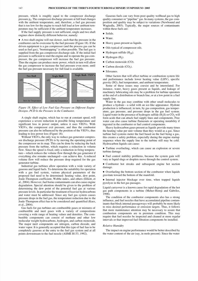
If the fuel supply pressure is not sufficient, single and two shaftengines show distinctly different behavior, namely:• A two shaft engine will run slower, such that the pressure in thecombustor can be overcome by the fuel pressure (Figure 18). If thedriven equipment is a gas compressor (and the process gas can beused as fuel gas), “bootstrapping” is often possible. The fuel gas issupplied from the gas compressor discharge side. If the initial fuelpressure is sufficient to start the engine and to operate the gas com-pressor, the gas compressor will increase the fuel gas pressure.Thus the engine can produce more power, which in turn will allowthe gas compressor to increase the fuel pressure even more, untilthe fuel gas pressure necessary for full load is available.
Figure 18. Effect of Low Fuel Gas Pressure on Different Engine Designs. PCD Is the Pressure in the Combustor.
A single shaft engine, which has to run at constant speed, willexperience a severe reduction in possible firing temperature andsignificant loss in power output, unless it uses VIGVs. WithVIGVs, the compressor exit pressure, and thus the combustorpressure can also be influenced by the position of the VIGVs, thusleading to less power loss (Figure 18).
Without VIGVs, the only way to reduce gas generator compres-sor discharge pressure (PCD) is by moving the operating point of the compressor on its map. This can be done by reducing the back
pressure from the turbine, which requires a reduction in volumeflow. Since the speed is fixed, only a reduction in firing tempera-ture—which reduces the volume flow through the gas generator if everything else remains unchanged—can achieve this. A reducedvolume flow will reduce the pressure drop required for the gasgenerator turbine.
Industrial gas turbines allow operation with a wide variety of gaseous and liquid fuels. To determine the suitability for operationwith a gas fuel system, various physical parameters of theproposed fuel need to be determined: heating value, dew point,Joule-Thompson coefficient, Wobbe index, and others (Elliott, etal., 2004). However, fuel borne contaminants can also cause enginedegradation. Special attention should be given to the problem of determining the dew point of the potential fuel gas at variouspressure levels. In particular the treatment of heavier hydrocarbonsand water must be addressed. Since any fuel gas system causespressure drops in the fuel gas, the temperature reduction due to theJoule-Thompson effect has to be considered and quantified (Kurz,et al., 2004).
Gas fuels for gas turbines are combustible gases or mixtures of combustible and inert gases with a variety of compositionscovering a wide range of heating values and densities. The com-bustible components can consist of methane and other lowmolecular weight hydrocarbons, hydrogen, and carbon monoxide.The major inert components are nitrogen, carbon dioxide, andwater vapor. It is generally accepted that this type of fuel has to becompletely gaseous at the entry to the fuel gas system and at allpoints downstream to the fuel nozzle (ASME B133, 1992).
Gaseous fuels can vary from poor quality wellhead gas to hquality consumer or “pipeline” gas. In many systems, the gas cposition and quality may be subject to variations (NewboundWagiealla, 2003). Typically, the major sources of contaminawithin these fuels are:
• Solids.
• Water.
• Heavy gases present as liquids.
• Oils typical of compressor oils.• Hydrogen sulfide (H2S).• Hydrogen (H2).
• Carbon monoxide (CO).
• Carbon dioxide (CO2).
• Siloxanes.Other factors that will affect turbine or combustion system
and performance include lower heating value (LHV), specgravity (SG), fuel temperature, and ambient temperature.
Some of these issues may coexist and be interrelated. instance, water, heavy gases present as liquids, and leakagemachinery lubricating oils may be a problem for turbine operat the end of a distribution or branch line, or at a low point in asupply line.Water in the gas may combine with other small moleculeproduce a hydrate—a solid with an ice-like appearance. Hydproduction is influenced, in turn, by gas composition, gas temature, gas pressure, and pressure drops in the gas fuel systLiquid water in the presence of hydrogen sulfide (H2S) or CO2 willform acids that can attack fuel supply lines and components. water can also cause turbine flameouts or operating instabiliingested in the combustor or fuel control components.
Heavy hydrocarbon gases present as liquids provide many tthe heating value per unit volume than they would as a gas. Sturbine fuel systems meter the fuel based on the fuel being a this creates a safety problem, especially during the engine stasequence when the supply line to the turbine still may be cHydrocarbon liquids can cause:
• Turbine overfueling, which can cause an explosion or sevturbine damage.• Fuel control stability problems, because the system gain vary as liquid slugs or droplets move through the control syst• Combustor hot streaks and subsequent engine hot secdamage.• Overfueling the bottom section of the combustor when liqgravitate toward the bottom of the manifold.• Internal injector blockage over time, when trapped liqupyrolyze in the hot gas passages.Liquid carryover is a known cause for rapid degradation of thgas path components in a turbine (Meher-Homji and Gabr1998).
The condition of the combustor components also has a stronginfluence, and fuel nozzles that have accumulated pipeline contam-inants that block internal passageways will probably be more likelyto miss desired performance or emission targets. Thus, it followsthat more maintenance attention may be necessary to assure thatcombustion components are in premium condition. This mayrequire that fuel nozzles be inspected and cleaned at more regularintervals or that improved fuel filtration components be installed.
Relative Humidity
The impact on engine performance would be better describethe water content of the air (say, in mole percent). Since the w
PROCEEDINGS OF THE THIRTY-FOURTH TURBOMACHINERY SYMPOSIUM • 2005142

8/12/2019 Gas Turbine Performance by Rainer Kurz
http://slidepdf.com/reader/full/gas-turbine-performance-by-rainer-kurz 13/16
concentration in the air for the same relative humidity increaseswith increasing temperature, the effects on engine performance arenegligible for low ambient temperatures and fairly small (in therange of 1 or 2 percent) even at high temperatures of 38°C (100°F).Since the water content changes the thermodynamic properties of air (such as density and heat capacity), it causes a variety of changes in the engine, such that on some engines performance isincreased with increased humidity, while other engines showreduced performance at increased humidity.
WHAT DO TYPICAL MAPS SHOW?Because the gas turbine performance varies significantly from
one design to the other, the procedure to determine the perform-ance of the engine for a specified operating point is to use themanufacturer’s performance maps.
Typical engine performance maps are shown in Figure 14c forsingle shaft engines and in Figure 14a and b for two shaft engines.In general, these maps can be used to determine the engine full loadoutput at a given ambient temperature and a given power turbinespeed. They also show the fuel flow at any load, as well as exhaustflow and temperature. Additional maps allow correction for inletand exhaust losses as well as for the site elevation. For diagnosticpurposes, the maps also allow determination of the expected com-pressor discharge pressure, control temperature (typically powerturbine inlet temperature or exhaust temperature), and gas generatorspeed at any operating point. Discrepancies between the expectedand the actual values may be indicative of engine problems.
In order to fully understand the information displayed on engineperformance maps, one wants to determine what the reason is foran engine to behave the way it does.
API 616 (1998) prescribes another form of representing engineperformance than described above. The map for single shaftengines in API 616 (1998) is not particularly useful for single shaftengines driving generators, because it shows the performance as afunction of gas generator speed. For these generator set applica-tions, however, the gas generator speed is always constant. TheAPI 616 maps used to represent two shaft engines do not allowdescription of the engine performance at varying ambient temper-atures. Also, the control temperature for two shaft engines isusually not the exhaust temperature (as postulated in one of theAPI 616 curves), but the power turbine inlet temperature. The mostuseful curve in API 616 is essentially a subset of the power turbinecurve in Figure 14b.
It should be noted that, particularly in the field, the measurementof power output, heat rate, exhaust flow, and exhaust temperatureare usually rather difficult (Brun and Kurz, 2001). Understandingthe operating principles of the engine is therefore a useful tool of interpreting data.
PERFORMANCE DEGRADATIONAny prime mover exhibits the effects of wear and tear over time.
The problem of predicting the effects of wear and tear on the per-formance of any engine is still a matter of discussion. Because thefunction of a gas turbine is the result of the finetuned cooperationof many different components, the gas turbine has to be treated asa system, rather than as isolated components (Kurz and Brun,2001).Treating the gas turbine package as a system reveals the effectsof degradation on the match of the components as well as on thematch with the driven equipment. The mechanisms that causeengine degradation, are:• Changes in blade surfaces due to erosion or fouling, and theeffect on the blade aerodynamics.• Changes in seal geometries and clearances, and the effect onparasitic flows.• Changes in the combustion system (e.g., which result indifferent pattern factors).
The function of a gas turbine is the result of the finetuned ceration of many different components. Any of these parts can swear and tear over the lifetime of the package, and thus adversely affect the operation of the system. In particular the adynamic components, such as the engine compressor, the turbthe driven pump or compressor have to operate in an environthat will invariably degrade their performance. The understanof the mechanisms that cause degradation, as well as the effthat the degradation of certain components can cause for overall system, are a matter of interest.
Several mechanisms cause the degradation of engines:• Fouling is caused by the adherence of particles to airfoils annulus surfaces. The adherence is caused by oil or water mThe result is a buildup of material that causes increased surfroughness and to some degree changes the shape of the airfothe material buildup forms thicker layers of deposits). Many ocontaminants are smaller than 2µm. Fouling can normally be elim-inated by cleaning.• Hot corrosion is the loss of material from flow path componcaused by chemical reactions between the component and cecontaminants, such as salts, mineral acids, or reactive gases. products of these chemical reactions may adhere to the aerocponents as scale. High temperature oxidation, on the other hanthe chemical reaction between the component’s metal atoms oxygen from the surrounding hot gaseous environment. Thetection through an oxide scale will in turn be reduced by mechanical damage such as cracking or spalling, for examduring thermal cycles.• Erosion is the abrasive removal of material from the flow path byhard particles impinging on flow surfaces. These particles typicallyhave to be larger than 20 µ m in diameter to cause erosion byimpact. Erosion is probably more a problem for aeroengine appli-cations, because state-of-the-art filtration systems used forindustrial applications will typically eliminate the bulk of the largerparticles. Erosion can also become a problem for driven compres-sors or pumps where the process gas or fluid carries solid materials.
• Damage is often caused by large foreign objects strikingflow path components. These objects may enter the engine witinlet air, or the gas compressor with the gas stream, or are the rof broken off pieces of the engine itself. Pieces of ice breakinthe inlet, or carbon buildup breaking off from fuel nozzles cancause damage.• Abrasion is caused when a rotating surface rubs on a statiosurface. Many engines use abradable surfaces, where a ceramount of rubbing is allowed during the run-in of the enginorder to establish proper clearances. The material removal typically increase seal or tip gaps.While some of these effects can be reversed by cleaningwashing the engine, others require the adjustment, repair,replacement of components.
It should be noted that the determination of the exact amounperformance degradation in the field is rather difficult. Test untainties are typically significant, especially if packainstrumentation as opposed to a calibrated test facility is u
Even trending involves significant uncertainties, because incases the engine performance has to be corrected from datum ditions to a reference condition.
Three major effects determine the performance deterioratiothe compressor:• Increased tip clearances• Changes in airfoil geometry• Changes in airfoil surface qualityWhile the first two effects typically lead to nonrecoverable dedation, the latter effect can at least partially be reversed by wasthe compressor.
GAS TURBINE PERFORMANCE 143

8/12/2019 Gas Turbine Performance by Rainer Kurz
http://slidepdf.com/reader/full/gas-turbine-performance-by-rainer-kurz 14/16
The overall effect of degradation on an engine compressoryields added losses and lower capability of generating head.Typically, a degraded compressor also will have a reduced surge orstall margin (Spakovszki, et al., 1999). This will not have any sig-nificant effect on the steady-state operation, as long as other effectsthat lower the stall margin (such as water or steam injection) areavoided (Brun, et al., 2005). For a given speed of a degraded com-pressor, each subsequent stage will see lower Mach numbers(because of the higher temperature) and an increased axial velocitycomponent (becauseρ = p/RT, where p is reduced, T is increased,
thus the density gets reduced).The net effect will be that, while in the new machine all stageswere working at their optimum efficiency point at design surgemargins, the degradation will force all stages after the first one towork at off-optimum surge margins and lower than design effi-ciency. This will not only lower the overall efficiency and thepressure ratio than can be achieved, but also the operating range.
Calculations for a typical axial compressor (Kurz and Brun,2001) reveal that the combined effects of airfoil fouling andincreased clearances lead to loss of pressure ratio, loss of effi-ciency, and loss of range or stall margin. In particular the increasedclearances cause choke at lower flow.
Recoverable and Nonrecoverable Degradation
The distinction between recoverable and nonrecoverable degra-
dation is somewhat misleading. The majority of degradation isrecoverable; however the effort is very different depending on thetype of degradation. The recovery effort may be as small as wateror detergent online washing, or detergent on-crank washing. Thedegradation recovery by any means of washing is usually referredto as recoverable degradation. However, a significant amount of degradation can be recovered by engine adjustments (such asresetting variable geometry). Last, but not least, various degrees of component replacement in overhaul can bring the system perform-ance back to as-new conditions.
Protection Against Degradation
While engine degradation cannot entirely be avoided, certainprecautions can clearly slow the effects down. These precautionsinclude the careful selection and maintenance of the air filtration
equipment, and the careful treatment of fuel, steam, or water thatare injected into the combustion process. It also includes obeyingmanufacturers’ recommendations regarding shutdown and restart-ing procedures. For the driven equipment surge avoidance, processgas free of solids and liquids and operation within the design limitsneed to be mentioned. With regards to steam injection, it must benoted that the requirements for contaminant limits for a gas turbineare, due to the higher process temperatures, more stringent than fora steam turbine.
The site location and environment conditions, which dictateairborne contaminants, their size, concentration, and composition,need to be considered in the selection of air filtration. Atmosphericconditions, such as humidity, smog, precipitation, mist, fog, dust,oil fumes, industrial exhausts, will primarily affect the engine com-pressor. Fuel quality will impact the hot section. The cleanliness of the process gas, entrained particles, or liquids will affect the drivenequipment performance. Given all these variables, the rate of degradation is impossible to predict with reasonable accuracy.
Thorough on-crank washing can remove deposits from theengine compressor blades and is an effective means for recoveringdegradation of the engine compressor. The engine has to be shutdown and allowed to cool down prior to applying detergent to theengine compressor while it rotates at slow speed. Online cleaning,where detergent is sprayed into the engine running at load, canextend the periods between on-crank washing, but it cannot replaceit. If the compressor blades can be accessed with moderate effort(for example, when the compressor casing is horizontally split),hand cleaning of the blades can be very effective.
TRANSIENT BEHAVIORAll the above considerations were made with the assump
that the engine operates at steady-state conditions. The aushould briefly discuss the engine operation during load transii.e., when load is added or removed.
Figure 19 shows the engine limits (for a two shaft engine) fstart to the full load design point. The engine initially is accelerby a starter. At a certain gas power (GP) speed, fuel is injectedlight-off occurs. The fuel flow is increased until the first limaximum firing temperature, is encountered. The engine contito accelerate, while the fuel flow is further increased. Soon,surge limit of the engine compressor limits the fuel flow. Whilstarter continues to accelerate the engine, a point is reached wthe steady-state operating line can be reached without violasurge or temperature limits. At this point, the engine can opeself sustaining, i.e., the starter can disengage. The maximum aceration (i.e., the maximum load addition) can now be achieveincreasing to the maximum possible fuel flow. However, maximum possible fuel flow is limited by either the surge limthe engine compressor or the maximum firing temperature. Iload suddenly drops, the maximum rate deceleration is limitethe flameout limits of the engine.
Figure 19. Start and Acceleration Map for a Gas Turbine.
CONCLUSIONThe previous pages have given some insight into the work
principles of a gas turbine, and what the effect of these workprinciples on the operating characteristics of gas turbines is. Bon this foundation, it was explained what the effects of changambient temperature, barometric pressure, inlet and exhaust lorelative humidity, accessory loads, different fuel gases, or chain power turbine speed are. The topics presented aim at enhanthe understanding of the operation principles of a gas turbinindustrial applications.
NOMENCLATUREA = Through-flow areac = Velocity vector in stationary framecp = Specific heatEf = Lower heating valueh = EnthalpyL = LengthM = Mach numberMn = Machine Mach numberN = Rotational speed in rpmNGP = Gas generator speedp = Stagnation pressureP = PowerQ = Volumetric flow rateq = Heat flowR = Specific gas constant
PROCEEDINGS OF THE THIRTY-FOURTH TURBOMACHINERY SYMPOSIUM • 2005144

8/12/2019 Gas Turbine Performance by Rainer Kurz
http://slidepdf.com/reader/full/gas-turbine-performance-by-rainer-kurz 15/16
s = EntropyT = TemperatureU = Blade velocityV = Velocity vectorW = Mass flow ratesw = Velocity vector in rotating frame∆ = Differenceη = Efficiency τ = Torqueγ = Specific heat ratioω = Rotational speed in rad/sec = 2?N/60
Subscripts
1 = At engine inlet2 = At engine compressor exit3 = At turbine inlet5 = At power turbine inlet7 = At engine exitt = Turbinec = CompressorI = Tangential direction
APPENDIX A—GAS TURBINE CYCLE CALCULATION
A gas turbine may be designed for the following parameters forthe compressor:
• pa = 14.73 psia (1.013 bara) p2 = 147.3 psia (10.13 bara) W =100 lb/s (45 kg/s) = 85 percent• Ta = 100°F (37.8°C) = 560 R (311 K)and the turbine (neglecting the fuel mass flow and the combustorpressure drop):• pa = 14.73 psia (1.013 bara) p3 = 147.3 psia (10.13 bara) W =100 lb/s (45 kg/s) = 85 percent• T3 = 1600°F (870°C) = 2060 R (1144 K)
One uses the relationships for work H and power P:
(A-1)
and the gas properties for air: cp = 0.24 Btu/lbR (1.007 kJ/kgK);γ= 1.4 (this is a simplified assumption, because the gas properties of the exhaust gas are somewhat different from air).
The compressor temperature rise is:
(A-2)
and the compressor discharge temperature is therefore:
(A-3)
This indicates that the compressor consumed the work:
(A-4)
and the power:
(A-5)
The power extraction of the turbine causes a temperature drop:
(A-6)
and thus an exhaust temperature of:
(A-7)
Thereby extracting the work:
(A-8)
producing a power of:
(A-9)
The net engine output is the difference between the poproduced by the turbine and absorbed by the compressor:
(A-10)
With a compressor exit temperature of 713°F (379°C) anturbine inlet temperature of 1600°F (870°C), one needs to addto bring the gas from 713°F (379°C) to 1600°F (870°C):
(A-11)
With this, the engine heat rate can be calculated from:
(A-12)
and the thermal efficiency is:
(A-13)
APPENDIX B—THERMODYNAMICAL PARAMETERSFOR EXHAUST GASES
The specific heat and ratios of specific heats, which determthe performance of the turbine section, depend on the fuel to
ratio, the fuel composition, and the relative humidity of the airmain constituents of the exhaust gas are nitrogen, oxygen, cadioxide, and water. The specific heat (cp) and gas constant (R) of all these constituents are known, so it is easy to calculate overall cp andγ, once the mole fractions of the constituents yi areknown:
(B-1)
Table B-1 givesγ, cp, and R of the above substances at 10 ba800°C (145.04 psi, 1472°F).
Table B-1. Specific Heat (C p), Ratio of Specific Heats and GasConstants (R) for Some Components of the Exhaust Gas.
GAS TURBINE PERFORMANCE 145
H c T
P W H
p=
=
∆
( )T T T p
p R K
c2 1
1 2
1
1
1 613 341− =
− =
−
η
γ
γ
( )560 613 713 379 R R F C + = ° °
( ) P lb s Btu lb Btu s hp
kg s kJ kg kJ s kW
= × = =
= × = =
100 147 14700 20800
45 344 15480 15480
/ / /
/ / /
( )T T T p
p R K 3 7 1 3
7
3
1 844 469
1
− = −
=
−
η
γ
γ
( ) H Btu lb kj kg = × = = × =
. / . / ,24 613 147 1007 341 344
( )T F C 7 1600 844 756 1144 469 402= − = ° = − = °
( ) H Btu lb kJ kg = × = = × =. / . / ,24 844 202 1007 469 472
( ) P lb s Btu lb Btu s hp
kg s kJ kg kJ s kW
= × = =
= × = =
100 202 20200 28583
45 472 21240 21240
/ / /
/ / /
( ) P hp hp hp
kW kW kW net
= − =
= − =
28583 20800 7783
21240 15480 5760
( )( )( )
Q W c T Btu s MMBtu hr
kJ s GJ hr
p= = × × − = =
= × × − = =
∆ 100 0 24 1600 713 21300 76 7
45 1007 870 379 22250 80 1
. / . /
. / . /
( ) HR Btu hphr
kJ kWh
= =
= =
767 7783 9850
801 5760 13900
. / /
. / / ,
η th kW kJ s= =5760 22250 25 9%/ / .
c y c
c
c R
p i p ii
N
p
p m
=
=−
=
∑ ,
1
γ
cp (kJ/kgK) R (kJ/kgK) = 1/(1-R/cp)
Air 1.156 287 1.33
CO 2 1.255 189 1.18
H 2O 2.352 461 1.24

8/12/2019 Gas Turbine Performance by Rainer Kurz
http://slidepdf.com/reader/full/gas-turbine-performance-by-rainer-kurz 16/16
Assuming an expansion over a constant pressure ratio andconstant efficiency, then:
(B-2)
Thus, the temperature differential over the turbine depends onthe fuel gas composition and the water content of the inlet air. The
practical consequence of the above is the fact that most enginesmeasure T5 rather than T3 for control purposes. The ratio T5/T3 isoften assumed constant. However, in reality it is dependent on thefuel to air ratio, the fuel gas, and the water content of the air (i.e.,the relative humidity and the ambient temperature).
Another effect that must be considered is the fact that the rela-tionship between the pressure ratio and the Mach number dependon γ. That means that the maximum volumetric flow through thefirst stage GP nozzle and the first stage PT nozzle also depend onthe exhaust gas composition, which means that different fuel com-positions (if the differences are very large) can influence the enginematch.
REFERENCESAPI Standard 616, 1998, “Gas Turbines for Refinery Service,”
Fourth Edition, American Petroleum Institute, Washington,D.C.ASME/ANSI Standard B133, 1992, “Gas Turbine Procurement,”
American Society of Mechanical Engineers, New York, NewYork.
Brun, K., Kurz, R., and Simmons, H., 2005, “Aerodynamic In-stability and Life Limiting Effects of Inlet and Interstage WaterInjection into Gas Turbine Axial Compressors,” ASMEGT2005-68007.
Brun, K. and Kurz, R., 2001, “Measurement Uncertainties En-countered During Gas Turbine Driven Compressor FieldTesting,” ASME Journal of Engineering for Gas Turbines and Power , 123 , pp. 62-69.
Cohen, H., Rogers, G. F. C., and Saravanamuttoo, H. I. H., 1996,Gas Turbine Theory , New York, New York: LongmanScientific & Technical.
Elliott, F. G., Kurz, R., Etheridge, C., and O’Connell, J. P., 20“Fuel System Suitability Considerations for Industrial GTurbines,” ASME Journal of Engineering for Gas Turbinesand Power , 126 , pp. 119-126.
Greenwood, S. A., 2000, “Low Emission Combustion Technofor Stationary Gas Turbine Engines,”Proceedings of theTwenty-Ninth Turbomachinery Symposium , TurbomachineryLaboratory, Texas A&M University, pp. 125-134.
Kurz, R., 1991, “Transonic Flow Through Turbine Cascades 3 Different Pitch-to-Chord Ratios,” Proceedings of the 1ISABE, Nottingham, England.
Kurz, R. and Brun, K., 2001, “Degradation in Gas TurbSystems,” ASME Journal of Engineering for Gas Turbinesand Power , 123 , pp. 70-77.
Kurz, R. , Brun, K., and Legrand, D. D., 1999, “Field PerformTesting of Gas Turbine Driven Compressor Sets,”Proceedingsof the Twenty-Eighth Turbomachinery Symposium , Turboma-chinery Laboratory, Texas A&M University, pp. 213-230.
Kurz, R., Etheridge, C., and Kaiser, R., 2004, “On Fuel Suitabfor Gas Turbines,”Proceedings of the Thirty-Third Turbo-machinery Symposium , Turbomachinery Laboratory, TexasA&M University, pp. 67-75.
Meher-Homji, C. B. and Gabriles, G. A., 1998, “Gas Turbine BFailures—Causes, Avoidance, and Troubleshooting,”Pro-ceedings of the Twenty-Seventh Turbomachinery Symposium ,Turbomachinery Laboratory, Texas A&M University, pp. 1180.
Newbound, T. D. and Wagiealla, W., 2003, “On-Line HydrocaDew Point Monitoring in Fuel Gas,” ASME GT2003-388
Spakovszky, Z. S., Gertz, J. B., Sharma, O. P., Paduano, J. Epstein, A. H., and Greitzer, E. M., 1999, “Influence Compressor Deterioration on Engine Dynamic Behavior Transient Stall Margin,” ASME 99-GT-439.
Schodl, R., 1977, “Entwicklung des Laser-Zwei-Fokus Verfahfuer die beruehrungslose Messung der Stroemungsvektoinsbesondere in Turbomaschinen,” Dissertation RWAachen, Germany.
PROCEEDINGS OF THE THIRTY-FOURTH TURBOMACHINERY SYMPOSIUM • 2005146
∆ ∆ ∆T
hc
hc
T p
p p ex
t s
p ext = = = −
−
, ,
η η
γ
γ
35
31
1