generation interconnection facility study report for pjm
TRANSCRIPT
Generation Interconnection Facility Study Report
For
PJM Generation Interconnection Request
Queue Position Z1-069
Gold-Sabinsville 115kV
August 2015

© PJM Interconnection 2015. All rights reserved. 2 Z1-069 Gold-Sabinsville 115kV
A. Transmission Owner Facilities Study Summary
1. Description of Project Big Level Wind LLC (hereinafter referred to as “Developer”) has proposed the addition of 70 MW of WIND generation with 19% (13.3 MW) capacity to the Potter – Niles Valley 115kV kV circuit between Gold substation and Sabinsville substation, approximately five (5) miles from Gold substation. This means that the remaining 56.7 MW can be curtailed should a system reliability constraint occur.
This project is generally located in north-central Pennsylvania (Potter County). The generation facility will interconnect with Pennsylvania Electric Company, a FirstEnergy Company (FE), (hereinafter referred to as "Transmission Owner") at a new three-breaker ring bus-configured switching station (interconnection substation).
2. Amendments to the System Impact Study data or System Impact Study Results Combined/distributed “Engineering Oversight and Commissioning (EOC)” with the following:
n4492 (Line Loop) n4493 (Interconnection Substation) n4483 T-121 Interconnection Substation n4494 Niles Valley Substation
The following work has been removed from the scope of this project:
Add a wavetrap to the Z1-069 – Niles Valley line at Sabinsville substation. Update drawings, references and nameplates for line name change.
Carrier relay upgrade on Z1-069 and Farmers Valley line exits at Potter substation.
3. Interconnection Customer’s Submitted Milestone Schedule Developer’s requested Commercial Operation Date (COD) for the generation facility is December 30, 2017. Transmission Owner’s proposed schedule might not match Developer’s requested Milestone Schedule. A Project Kickoff meeting must occur by March 1, 2016 to meet the Milestone Schedule listed below:
Developer’s Requested Milestone Schedule:
06/01/2017 Initial Back-feed through Project Substation Date 12/30/2017 Project Commercial Operation Date

© PJM Interconnection 2015. All rights reserved. 3 Z1-069 Gold-Sabinsville 115kV
A proposed fifteen (15)-month Direct Connection and Non-Direct connection schedule is estimated to complete the engineering, construction and associated activities, which are detailed in the “Direct Connection” and “Non-Direct Connection” sections below. In order to meet Developer’s requested Back-feed date of 06/01/2017, an Interconnection Construction Service Agreement must be fully-executed, and Construction Kick-Off Meeting must occur, by March 1, 2016.
4. Scope of Customer’s Work
Direct Connection Facilities
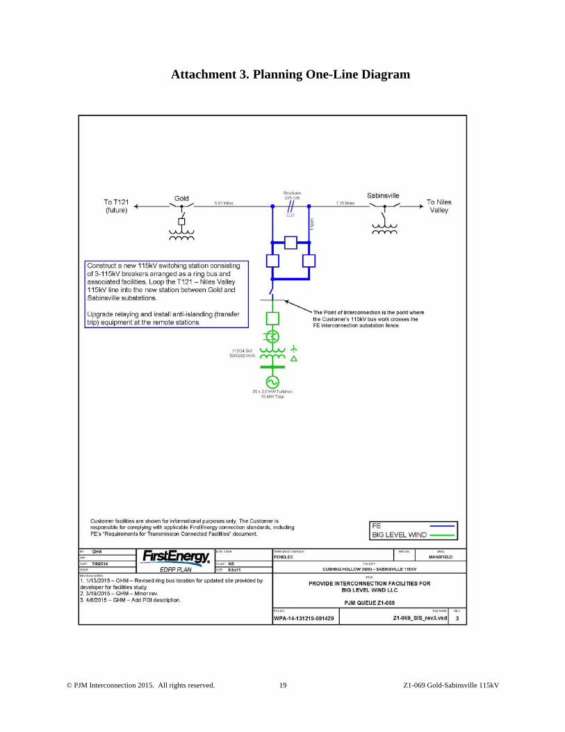
Developer will construct facilities, including the WIND collection system and generation step-up (GSU) transformer, and connect to the new 115 kV three-breaker ring bus. The interconnection point will be located at the point where Developer-owned facilities connect to the Transmission Owner-owned 115 kV three-breaker ring bus, as shown in the attached one-line diagram, Attachment 3.
Point of Interconnection (POI): the point where Developer’s 115 kV bus work crosses the Transmission Owner interconnection substation fence.
Developer is required to own, install, and maintain a fully-rated, fault-interrupting circuit breaker on the high-side of the GSU transformer, between the position on the three-breaker ring bus and the generating station.
The direct connection facilities include line terminal equipment on Transmission Owner’s side of the point of interconnection. This typically includes operational metering, dead-end structure, and a three-phase, gang-operated disconnect switch. These facilities are considered radial equipment from the terminal to the point of interconnection.
Project Scope
It is proposed that this project be connected via a new 115 kV three-breaker ring bus. The new interconnection substation is to be constructed on the Potter – Niles Valley 115kV kV circuit between Gold substation and Sabinsville substation, approximately 5 miles from Gold substation. The loop would extend approximately 200 ft. Developer is responsible for constructing all of the facilities on its side of the point of interconnection, which will be located at the point where the Developer-owned facilities connect to the Transmission Owner-owned 115 kV three-breaker ring bus, as shown in the attached one-line diagram, Attachment 3.
5. Description of Facilities Included in the Facilities Study
Direct Connection Facilities
1. Niles Valley-Potter 115kV line loop (PJM Network Upgrade Number n4492) 2. New 115kV ring bus substation (PJM Network Upgrade Number n4493)

© PJM Interconnection 2015. All rights reserved. 4 Z1-069 Gold-Sabinsville 115kV
Non-Direct Connection Facilities
3. Protection changes at T121 substation (PJM Network Upgrade Number n4483) 4. Protection changes at Niles Valley substation (PJM Network Upgrade Number n4494)
6. Total Costs of Transmission Owner Facilities included in Facilities Study The following table summarizes the total estimated costs according to FERC criteria. The estimated costs are in 2015 dollars. The taxes are a CIAC (Contribution in Aid of Construction) Federal Income Tax Gross Up charge. This tax may or may not be charged based on whether or not this project meets the eligibility requirements of IRS Notice 88-129.
Description NUN Estimated Cost Tax (if applicable)
Direct Connection Facilities Niles Valley-Potter 115kV line loop N4492 $ 377,100 $ 116,000New 115kV ring bus substation N4493 $ 6,130,300 $ 1,904,500 Non-Direct Connection Facilities Protection changes at T121 substation N4483 $ 307,100 $ 95,-000Protection changes at Niles Valley substation
N4494 $ 280,400 $ 86,800
Total Estimated Costs $ 7,094,900 $ 2,202,300
7. Summary of Milestone Schedules for Completion of Work Included in Facilities Study: A proposed fifteen (15)-month Direct Connection and Non-Direct Connection schedule is estimated to complete the engineering, construction and the associated activities, from the date of a fully executed Interconnection Construction Service Agreement and Construction Kick-Off Meeting. This schedule assumes that all issues covered by the “Environmental, Real Estate and Permitting Issues” section of this document are resolved, and outages will occur as planned. Construction can not begin until after all applicable permits and/or easements have been obtained.
Activity Start Month
End Month
Preliminary Engineering 1 2 Permits & Real Estate 6 9 Detailed Engineering 4 14 Equipment Procurement - Delivery 3 14 Below Grade Construction 8 14 Above Grade Construction 12 15 Testing & Commissioning 14 15
© PJM Interconnection 2015. All rights reserved. 5 Z1-069 Gold-Sabinsville 115kV
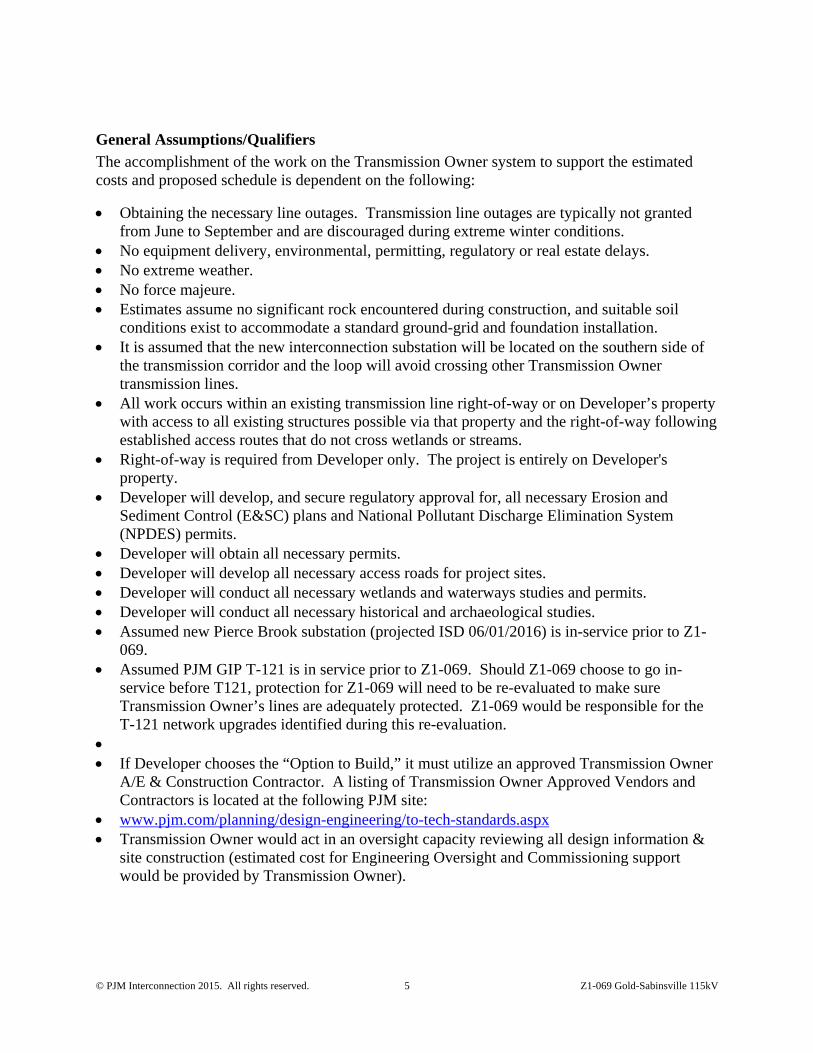
General Assumptions/Qualifiers
The accomplishment of the work on the Transmission Owner system to support the estimated costs and proposed schedule is dependent on the following:
Obtaining the necessary line outages. Transmission line outages are typically not granted from June to September and are discouraged during extreme winter conditions.
No equipment delivery, environmental, permitting, regulatory or real estate delays. No extreme weather. No force majeure. Estimates assume no significant rock encountered during construction, and suitable soil
conditions exist to accommodate a standard ground-grid and foundation installation. It is assumed that the new interconnection substation will be located on the southern side of
the transmission corridor and the loop will avoid crossing other Transmission Owner transmission lines.
All work occurs within an existing transmission line right-of-way or on Developer’s property with access to all existing structures possible via that property and the right-of-way following established access routes that do not cross wetlands or streams.
Right-of-way is required from Developer only. The project is entirely on Developer's property.
Developer will develop, and secure regulatory approval for, all necessary Erosion and Sediment Control (E&SC) plans and National Pollutant Discharge Elimination System (NPDES) permits.
Developer will obtain all necessary permits. Developer will develop all necessary access roads for project sites. Developer will conduct all necessary wetlands and waterways studies and permits. Developer will conduct all necessary historical and archaeological studies. Assumed new Pierce Brook substation (projected ISD 06/01/2016) is in-service prior to Z1-
069. Assumed PJM GIP T-121 is in service prior to Z1-069. Should Z1-069 choose to go in-
service before T121, protection for Z1-069 will need to be re-evaluated to make sure Transmission Owner’s lines are adequately protected. Z1-069 would be responsible for the T-121 network upgrades identified during this re-evaluation.
If Developer chooses the “Option to Build,” it must utilize an approved Transmission Owner
A/E & Construction Contractor. A listing of Transmission Owner Approved Vendors and Contractors is located at the following PJM site:
www.pjm.com/planning/design-engineering/to-tech-standards.aspx Transmission Owner would act in an oversight capacity reviewing all design information &
site construction (estimated cost for Engineering Oversight and Commissioning support would be provided by Transmission Owner).
© PJM Interconnection 2015. All rights reserved. 6 Z1-069 Gold-Sabinsville 115kV
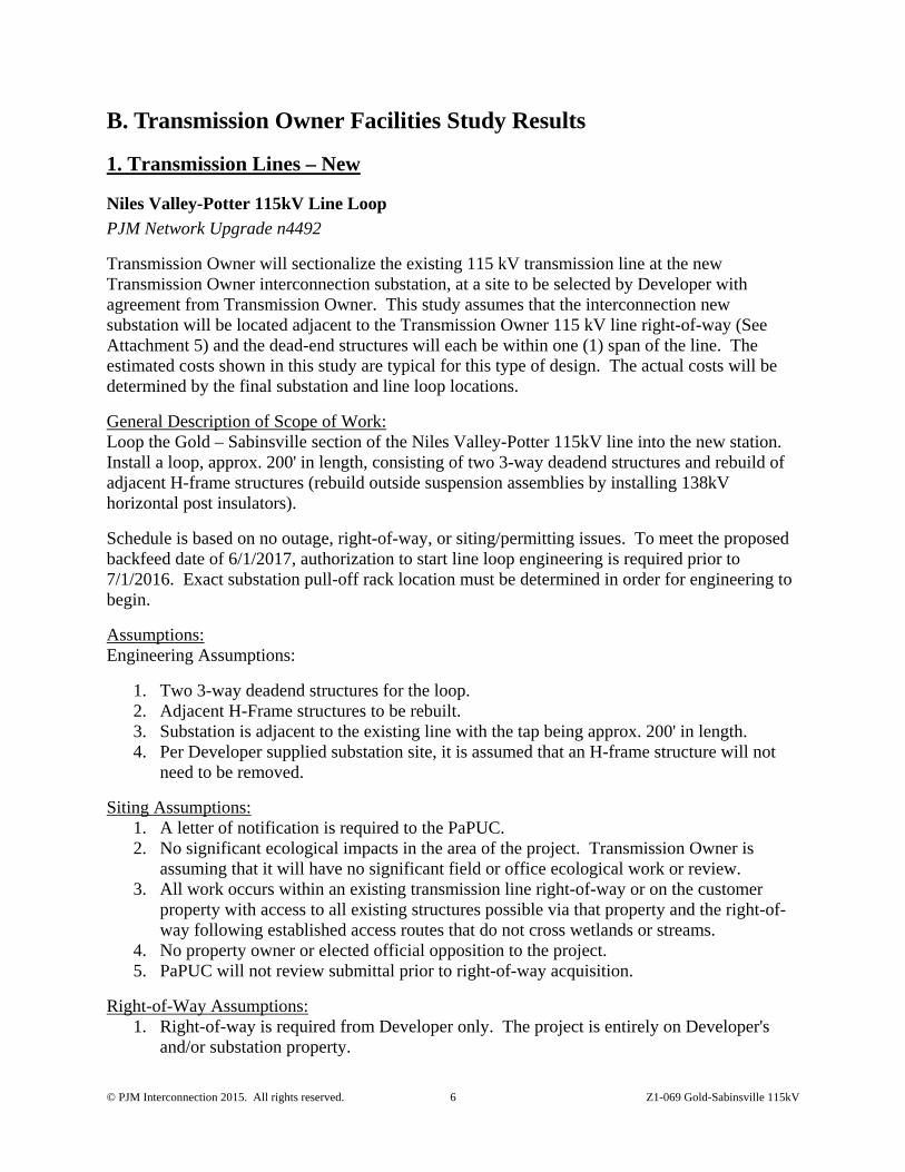
B. Transmission Owner Facilities Study Results
1. Transmission Lines – New
Niles Valley-Potter 115kV Line Loop
PJM Network Upgrade n4492
Transmission Owner will sectionalize the existing 115 kV transmission line at the new Transmission Owner interconnection substation, at a site to be selected by Developer with agreement from Transmission Owner. This study assumes that the interconnection new substation will be located adjacent to the Transmission Owner 115 kV line right-of-way (See Attachment 5) and the dead-end structures will each be within one (1) span of the line. The estimated costs shown in this study are typical for this type of design. The actual costs will be determined by the final substation and line loop locations.
General Description of Scope of Work: Loop the Gold – Sabinsville section of the Niles Valley-Potter 115kV line into the new station. Install a loop, approx. 200' in length, consisting of two 3-way deadend structures and rebuild of adjacent H-frame structures (rebuild outside suspension assemblies by installing 138kV horizontal post insulators).
Schedule is based on no outage, right-of-way, or siting/permitting issues. To meet the proposed backfeed date of 6/1/2017, authorization to start line loop engineering is required prior to 7/1/2016. Exact substation pull-off rack location must be determined in order for engineering to begin.
Assumptions: Engineering Assumptions:
1. Two 3-way deadend structures for the loop. 2. Adjacent H-Frame structures to be rebuilt. 3. Substation is adjacent to the existing line with the tap being approx. 200' in length. 4. Per Developer supplied substation site, it is assumed that an H-frame structure will not
need to be removed.
Siting Assumptions: 1. A letter of notification is required to the PaPUC. 2. No significant ecological impacts in the area of the project. Transmission Owner is
assuming that it will have no significant field or office ecological work or review. 3. All work occurs within an existing transmission line right-of-way or on the customer
property with access to all existing structures possible via that property and the right-of-way following established access routes that do not cross wetlands or streams.
4. No property owner or elected official opposition to the project. 5. PaPUC will not review submittal prior to right-of-way acquisition.
Right-of-Way Assumptions: 1. Right-of-way is required from Developer only. The project is entirely on Developer's
and/or substation property.

© PJM Interconnection 2015. All rights reserved. 7 Z1-069 Gold-Sabinsville 115kV
2. Right-of-way acquisition must occur prior to PaPUC review of LON submittal.
2. Transmission Line – Upgrades None.
3. New Substation/Switchyard Facilities
Transmission Owner Interconnection Substation
PJM Network Upgrade n4493
Transmission Owner will design, furnish and install the following for the new three-breaker 115 kV ring bus substation:
Three (3) 115 kV, 3000 ampere, 40 kA interrupting power circuit breakers Six (6) 115 kV, 2000 ampere, three-pole, manually-operated, group disconnect switches One (1) 115 kV, 2000 ampere, three-pole, motor-operated, disconnect switch Six (6) surge arresters for application on a 115 kV system Nine (9) 115 kV capacitor voltage transformers for relaying One (1) 115 kV power voltage transformer for station service Two (2) 115 kV transmission line termination structures 115 kV bus and conductor with associated structures Prefabricated building with battery and charger Transmission Owner relaying and controls per the Protection Requirements (provided as
Attachment 2). SCADA RTU Foundations for the equipment listed above. Substation fencing, cable trench & conduit system, ground grid and stoning.
Assumptions / Notes: A rough-graded, level site and access road is to be provided by Developer. Developer will acquire adequate land size to accommodate the Transmission Owner
interconnection substation. Transmission Owner did not perform an evaluation to determine if Developer has secured an adequate amount of land for the interconnection substation.
4. Upgrades to Substation / Switchyard Facilities
T-121 Interconnection Substation
PJM Network Upgrade n4483

© PJM Interconnection 2015. All rights reserved. 8 Z1-069 Gold-Sabinsville 115kV
Per the attached Protection Requirements, Transmission Owner will upgrade anti-islanding scheme and add BU DCB relaying for 115kV Z1-069 interconnection station line exit (Niles Valley line exit existing) and upgrade anti-islanding scheme for 115kV Potter line exit.
Assumptions / Notes: Estimates assume existing AC/DC systems are adequate for required additions. Estimates assume existing SCADA RTU system is adequate for required additions. Estimates assume T121 Interconnection Substation will be in service prior to the Z1-069
Interconnection Substation.
Niles Valley Substation
PJM Network Upgrade n4494
Per the attached Protection Requirements, Transmission Owner will upgrade anti-islanding scheme & install BU DCB relaying for 115kV Z1-069 interconnection station line exit (assume T121 interconnection station line exit exists) and upgrade anti-islanding scheme for 115kV Mansfield line exit.
Assumptions/Notes: Estimates assume existing AC/DC systems are adequate for required additions. Estimates assume existing SCADA RTU system is adequate for required additions. Estimates assume T121 Interconnection Substation will be in service prior to the Z1-069
Interconnection Substation.
5. Metering & Communications Developer shall install, own, operate, test and maintain the necessary revenue metering equipment. Developer shall provide Transmission Owner with dial-up communication to the revenue meter.
Transmission Owner’s Revenue Metering Requirements may be found in the Requirements for Transmission Connected Facilities document located at the following links:
www.firstenergycorp.com/feconnect www.pjm.com/planning/design-engineering/to-tech-standards.aspx
These requirements are in addition to any metering required by PJM.
Assuming Transmission Owner is installing the interconnection substation, Transmission Owner will provide the telecommunication circuits for the SCADA RTU and the telephone in the Transmission Owner interconnection substation.
Transmission Owner will obtain real-time, site-specific, generation data from PJM, via the required communication link from Developer to PJM. Transmission Owner will work with PJM and Developer to ensure the generation data provided to PJM meets Transmission Owner's requirements.

© PJM Interconnection 2015. All rights reserved. 9 Z1-069 Gold-Sabinsville 115kV
Communications for transmission line protection between the new interconnection substation, and the T-121 Interconnection Substation will be via Power Line Carrier (PLC).
Communications for transmission line protection between the new interconnection substation, and the Niles Valley Substation will be via Power Line Carrier (PLC).
Communications for transmission line protection between the new interconnection substation, and Developer’s generation (collector) substation, will be via fiber optics (see “Fiber Optic Communication Channels” section below).
Fiber Optic Communication Channels
Developer will design, provide, install, own and maintain a fiber optic communications cable between the new interconnection substation and the generation (collector) substation. Developer is responsible for obtaining and maintaining all associated Rights-of-Way (ROW), Easements, and Permits for its fiber cable.
6. Environmental, Real Estate and Permitting Issues The following are possible environmental, real estate and permitting issues:
Environmental permitting, Real Estate acquisition, and Pennsylvania Public Utility Commission (PUC) notification durations vary, some up to six (6) months after preliminary engineering is completed to provide the required information.
Prior to agreement by Developer to purchase the property, a Phase 1 Environmental Assessment should be conducted for the entire site to avoid assumption of environmental liabilities by Developer or Transmission Owner.
Based on a cursory review of the site, it is anticipated that some potential environmental issues that involve permitting or approvals could prolong the interconnection process. Therefore, if Transmission Owner will construct the interconnection substation and transmission line loop, Transmission Owner must receive the following before it will commit to the timeline in the Direct Connection and Non-Direct Connection Schedule section in this Facilities Study Report: A flat, rough-graded site with access road for the substation and corresponding transmission tap structures, with all state and federal, and local environmental permits and approvals for the interconnection substation and transmission line loop, relative to environmental requirements for:
erosion and sediment control management of stormwater encroachments on waterbodies and wetlands historic and archaeological resources
The Transmission Owner interconnection substation may involve environmental surveys, permits, approvals and plans with federal, state, and/or local agencies.
© PJM Interconnection 2015. All rights reserved. 10 Z1-069 Gold-Sabinsville 115kV
If Developer chooses the “Option to Build,” Developer will provide copies of all of the relative environmental permits and other necessary approvals to Transmission Owner before Transmission Owner accepts the interconnection facilities.
Developer is required to install an access road from the new interconnection substation to the nearest public road (must be approved by Transmission Owner), and obtain access rights for Transmission Owner. Developer is responsible to maintain access road and ensure unimpeded access for Transmission Owner at all times.
Developer is responsible for all property acquisition (including easements/rights-of-way (ROW) for transmission, distribution and communication facilities needed for the generator interconnection.
If Developer owns the project property, in fee title, Transmission Owner will require a fee property transfer for the interconnection substation site which may require subdivision approval, together with permanent access rights to and from the substation, as well as a perpetual easement for any transmission lines to the substation. Developer is responsible for all costs, including but not limited to subdivision, associated with the property transfer.
If Developer leases the project property, the Developer will be required to obtain fee property from the underlying fee property owner, on behalf of Transmission Owner, for the interconnection substation site, together with permanent access rights to and from the substation, as well as a perpetual easement for any transmission lines to the substation.
If Developer owns the project property, in fee title, Transmission Owner MAY consider acceptance of an exclusive perpetual substation easement, together with permanent access rights to and from the substation, as well as a perpetual easement for any transmission lines to the substation.
If Developer leases the project property, Transmission Owner MAY consider acceptance of an exclusive perpetual substation easement, together with permanent access rights to and from the substation, as well as a perpetual easement for any transmission lines to the substation.
All property rights must be surveyed and metes and bounds descriptions prepared for incorporation into Transmission Owner’s document forms, for transfer of title.
The Transmission Owner interconnection substation and transmission line loop may involve PA PUC notification/approval.
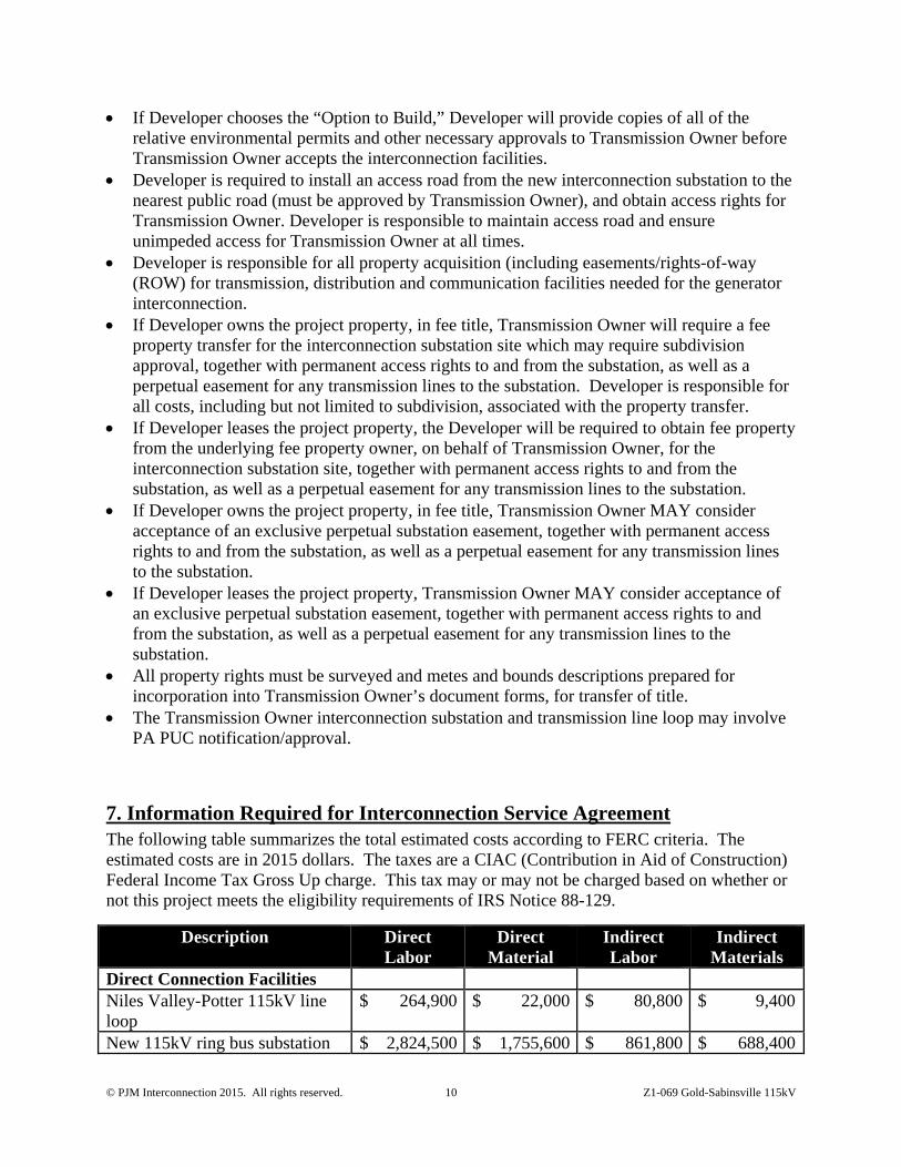
7. Information Required for Interconnection Service Agreement The following table summarizes the total estimated costs according to FERC criteria. The estimated costs are in 2015 dollars. The taxes are a CIAC (Contribution in Aid of Construction) Federal Income Tax Gross Up charge. This tax may or may not be charged based on whether or not this project meets the eligibility requirements of IRS Notice 88-129.
Description Direct Labor
Direct Material
Indirect Labor
Indirect Materials
Direct Connection Facilities Niles Valley-Potter 115kV line loop
$ 264,900 $ 22,000 $ 80,800 $ 9,400
New 115kV ring bus substation $ 2,824,500 $ 1,755,600 $ 861,800 $ 688,400

© PJM Interconnection 2015. All rights reserved. 11 Z1-069 Gold-Sabinsville 115kV
Description Direct Labor
Direct Material
Indirect Labor
Indirect Materials
Non-Direct Connection Facilities
Protection changes at T121 $ 173,800 $ 56,200 $ 53,100 $ 24,000Protection changes at Niles Valley
$ 163,600 $ 46,800 $ 50,000 $ 20,000
Total $ 3,426,800 $ 1,880,600 $ 1,045,700 $ 741,800
© PJM Interconnection 2015. All rights reserved. 12 Z1-069 Gold-Sabinsville 115kV
Attachment 1. Generation Protection Requirements
The proposed interconnection facilities must be designed in accordance with the Transmission Owner’s Requirements for Transmission Connected Facilities document located at either of the following links:
www.firstenergycorp.com/feconnect www.pjm.com/planning/design-engineering/to-tech-standards.aspx
If Developer chooses “Option to Build,” it will also be responsible for following Transmission Owner’s Approved Vendors and Contractors document located at the PJM site (second link above).
The following is an excerpt taken from Transmission Owner’s Requirements for Transmission Connected Facilities document:
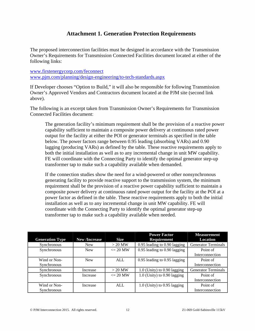
The generation facility’s minimum requirement shall be the provision of a reactive power capability sufficient to maintain a composite power delivery at continuous rated power output for the facility at either the POI or generator terminals as specified in the table below. The power factors range between 0.95 leading (absorbing VARs) and 0.90 lagging (producing VARs) as defined by the table. These reactive requirements apply to both the initial installation as well as to any incremental change in unit MW capability. FE will coordinate with the Connecting Party to identify the optimal generator step-up transformer tap to make such a capability available when demanded.
If the connection studies show the need for a wind-powered or other nonsynchronous generating facility to provide reactive support to the transmission system, the minimum requirement shall be the provision of a reactive power capability sufficient to maintain a composite power delivery at continuous rated power output for the facility at the POI at a power factor as defined in the table. These reactive requirements apply to both the initial installation as well as to any incremental change in unit MW capability. FE will coordinate with the Connecting Party to identify the optimal generator step-up transformer tap to make such a capability available when needed.
Generation Type New /Increase Size Power Factor Requirement
Measurement Location
Synchronous New > 20 MW 0.95 leading to 0.90 lagging Generator Terminals Synchronous New <= 20 MW 0.95 leading to 0.90 lagging Point of
Interconnection Wind or Non-Synchronous
New ALL 0.95 leading to 0.95 lagging Point of Interconnection
Synchronous Increase > 20 MW 1.0 (Unity) to 0.90 lagging Generator Terminals Synchronous Increase <= 20 MW 1.0 (Unity) to 0.90 lagging Point of
Interconnection Wind or Non-Synchronous
Increase ALL 1.0 (Unity) to 0.95 lagging Point of Interconnection

© PJM Interconnection 2015. All rights reserved. 13 Z1-069 Gold-Sabinsville 115kV
Induction generators and other generators with no inherent VAR (reactive power) control capability, or those that have a restricted VAR capability less than the defined requirements, must provide dynamic supplementary reactive support located at the generation facility with electrical characteristics equivalent to that provided by a similar-sized synchronous generator.
Design Requirements Developer is responsible for specifying appropriate equipment and facilities such that the parallel generation is compatible with Transmission Owner’s Transmission System. Developer is also responsible for meeting any applicable federal, state, and local codes.
Design Criteria Facilities owned and operated by Transmission Owner shall comply with the applicable Transmission Owner technical requirements and standards posted on the PJM website per the PJM Tariff, and the following criteria. Where there are different requirements for the same criterion, the more restrictive shall apply. Developer must abide by any PJM, RFC or NERC criteria imposed that is more restrictive than those of Transmission Owner.
General Design Requirements
System phasing (counter clockwise) 1-2-3 System frequency: 60 hertz Elevation, AMSL: 2254 feet Isokeraunic level: 40 Maximum ambient temperature: 40 degrees C Minimum ambient temperature: -40 degrees C Maximum conductor operating temperature: Contact Transmission Owner Wind Loading (round shapes): Per ASCE 7-98, per Fig. 6-1
depending on location Ice loading – Substations (no wind): 25 mm Seismic zone: Per ASCE 7-98, per Fig. 9.4.1.1(a)
and (b). Equipment qualification per IEEE 693-97
Voltage and Current Ratings
Nominal phase-to-phase: 115 kV Maximum phase-to-phase: 121 kV Basic impulse level (BIL): 550 kV Maximum continuous current carrying capacity: 2000 A Design fault current: 40 kA Single Contingency (breaker failure) clearing time: 30 cycles

© PJM Interconnection 2015. All rights reserved. 14 Z1-069 Gold-Sabinsville 115kV
Clearances and Spacing
Recommended rigid bus center-to-center phase spacing: 84” Minimum phase-to-phase, metal-to-metal distance: 53” Recommended phase-to-ground: 45” Minimum phase-to-ground: 42” Low bus height above top of foundations (match existing): 15’-1” High bus height above top of foundations (match existing): 21’-1” Minimum vertical clearance from live parts to grade: 11’-7” Minimum horizontal clearance from live parts: 6’-1” Minimum conductor clearance above roads in switchyard: 20’-2” Minimum bottom of insulator to top of foundation: 8’-6”

© PJM Interconnection 2015. All rights reserved. 15 Z1-069 Gold-Sabinsville 115kV
Attachment 2. Detailed Protection Requirements
Note: Assumed PJM GIP T-121 is in service prior to Z1-069. Should Z1-069 choose to go in-service before T121, protection for Z1-069 will need to be re-evaluated to make sure Transmission Owner’s lines are adequately protected.
Following is the protection scope information (Facilities Study Stage only) for the Z1-069 wind generation project. These relay requirements reflect only the project scope for the installation of the Z1-069 Interconnection Substation on the Potter – Niles Valley 115kV line, approximately 5.01 miles from Gold Tap towards Sabinsville Tap. Dual pilot relaying is required for stability on the Z1-069 – T121 115kV line and the Z1-069 – Niles Valley 115kV line. This study assumes that T121 will be in service prior to Z1-069, and that the Z1-069 Collector Substation will be directly adjacent to the Z1-069 Interconnection Substation.
Short Circuit Analysis Fault values for the Z1-069 Interconnection Substation location with the new generation in service are:
Three phase = 4923 A Single line to ground = 5605 A Z1= 1.4561 + j 10.0932 % Z0= 0.8489 + j 6.4192 %
Impedances are given on a 100 MVA and 115kV base. The fault currents provided are bolted, symmetrical values for normal system conditions, using the PJM Short Circuit case. Future increases in fault currents are possible and it is the Developer’s responsibility to upgrade its equipment and/or protective equipment coordination when necessary.
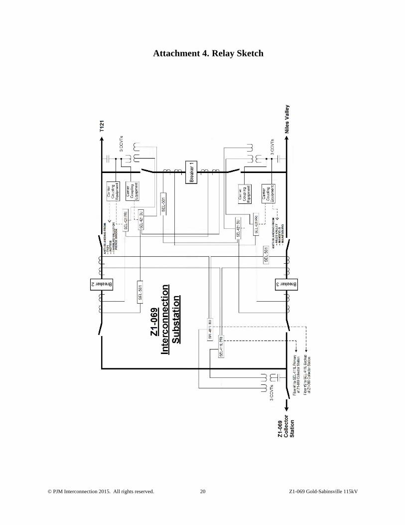
Z1-069 Interconnection Substation Construct a new three breaker 115kV ring bus. Install three SEL-501 relays, one per breaker, for Failure to Trip protection. Install three sets of three-phase CCVTs, one for each line exit. Install three SATEC meters, one per line exit. Install a GPS Clock, and SEL RTAC for remote relay access and SCADA distance to fault.
Z1-069 Interconnection Substation: T121 Interconnection Substation 115kV line exit – Install a dual pilot line protection scheme using SEL-421 primary and SEL-421 backup relays for Directional Comparison Blocking (DCB) over Power Line Carrier (PLC) using separate phases. These relays shall also provide step distance and directional overcurrent protection, reclosing, and sync check. Install one RFL-9780 Frequency Shift Keyed (FSK) Transmitter/Receiver (Tx/Rx) to transmit and receive anti-islanding to and from T121. Install two Ametek UPLC Tx/Rx units for the primary and backup DCB line protection schemes. For primary line protection and anti-islanding carrier coupling on one phase, install a wide band line tuner, wide band wave trap, and skewed hybrid. For backup line protection carrier coupling on a second phase, install a single-frequency line tuner and single-frequency wave trap.
© PJM Interconnection 2015. All rights reserved. 16 Z1-069 Gold-Sabinsville 115kV
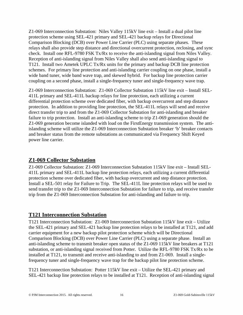
Z1-069 Interconnection Substation: Niles Valley 115kV line exit – Install a dual pilot line protection scheme using SEL-421 primary and SEL-421 backup relays for Directional Comparison Blocking (DCB) over Power Line Carrier (PLC) using separate phases. These relays shall also provide step distance and directional overcurrent protection, reclosing, and sync check. Install one RFL-9780 FSK Tx/Rx to receive the anti-islanding signal from Niles Valley. Reception of anti-islanding signal from Niles Valley shall also send anti-islanding signal to T121. Install two Ametek UPLC Tx/Rx units for the primary and backup DCB line protection schemes. For primary line protection and anti-islanding carrier coupling on one phase, install a wide band tuner, wide band wave trap, and skewed hybrid. For backup line protection carrier coupling on a second phase, install a single-frequency tuner and single-frequency wave trap.
Z1-069 Interconnection Substation: Z1-069 Collector Substation 115kV line exit – Install SEL-411L primary and SEL-411L backup relays for line protection, each utilizing a current differential protection scheme over dedicated fiber, with backup overcurrent and step distance protection. In addition to providing line protection, the SEL-411L relays will send and receive direct transfer trip to and from the Z1-069 Collector Substation for anti-islanding and breaker failure to trip protection. Install an anti-islanding scheme to trip Z1-069 generation should the Z1-069 generation become islanded with load on the FirstEnergy transmission system. The anti-islanding scheme will utilize the Z1-069 Interconnection Substation breaker ‘b’ breaker contacts and breaker status from the remote substations as communicated via Frequency Shift Keyed power line carrier.
Z1-069 Collector Substation Z1-069 Collector Substation: Z1-069 Interconnection Substation 115kV line exit – Install SEL-411L primary and SEL-411L backup line protection relays, each utilizing a current differential protection scheme over dedicated fiber, with backup overcurrent and step distance protection. Install a SEL-501 relay for Failure to Trip. The SEL-411L line protection relays will be used to send transfer trip to the Z1-069 Interconnection Substation for failure to trip, and receive transfer trip from the Z1-069 Interconnection Substation for anti-islanding and failure to trip.
T121 Interconnection Substation T121 Interconnection Substation: Z1-069 Interconnection Substation 115kV line exit – Utilize the SEL-421 primary and SEL-421 backup line protection relays to be installed at T121, and add carrier equipment for a new backup pilot protection scheme which will be Directional Comparison Blocking (DCB) over Power Line Carrier (PLC) using a separate phase. Install an anti-islanding scheme to transmit breaker open status of the Z1-069 115kV line breakers at T121 substation, or anti-islanding signal received from Potter. Utilize the RFL-9780 FSK Tx/Rx to be installed at T121, to transmit and receive anti-islanding to and from Z1-069. Install a single-frequency tuner and single-frequency wave trap for the backup pilot line protection scheme.
T121 Interconnection Substation: Potter 115kV line exit – Utilize the SEL-421 primary and SEL-421 backup line protection relays to be installed at T121. Reception of anti-islanding signal

© PJM Interconnection 2015. All rights reserved. 17 Z1-069 Gold-Sabinsville 115kV
from Potter shall send anti-islanding signal to Z1-069. Utilize the RFL-9780 FSK Tx/Rx to be installed at T121 on the Potter 115kV line exit.
Potter Substation Potter Substation: T121 Interconnection Substation 115kV line exit – Utilize existing SEL-321 primary and SEL-311A backup line protection relays. Utilize the carrier equipment (RFL-9780 Tx/Rx, wide band tuner, wide band wave trap, and skewed hybrid) to be installed for T121, to transmit breaker open status of the 115kV Bus Tie breaker at Potter substation, or anti-islanding signal received from Pierce Brook.
Potter Substation: Pierce Brook 115kV line exit – Pierce Brook substation is planned for construction between Potter and Farmers Valley, with a preliminary in-service date of 06/01/2016. Utilize the carrier equipment (RFL-9780 Tx/Rx, wide band tuner, wide band wave trap, and skewed hybrid) to be installed for T121, to receive breaker open status from Pierce Brook substation. If Pierce Brook is not in service before Z1-069, the anti-islanding scheme at Potter shall receive breaker open status from Farmers Valley substation. Reception of anti-islanding signal from Pierce Brook / Farmers Valley shall send an anti-islanding signal to the T121 Interconnection Substation.
Pierce Brook / Farmers Valley Substation Pierce Brook Substation: Potter 115kV line exit – Pierce Brook substation is planned for construction between Potter and Farmers Valley, with a preliminary in-service date of 06/01/2016. If Pierce Brook is in-service before Z1-069, the following changes will be made at Pierce Brook substation on the Potter 115kV line exit, with no changes at Farmers Valley. If Pierce Brook is not in-service before T121, the following changes will be made at Farmers Valley substation on the Potter 115kV line exit. Utilize the carrier equipment (RFL-9780 Tx/Rx, wide band tuner, wide band wave trap, and skewed hybrid) to be installed for T121, to transmit breaker open status of the Potter 115kV line breaker(s) at Pierce Brook / Farmers Valley substation.
Niles Valley Substation Niles Valley Substation: Z1-069 Interconnection Substation 115kV line exit – Utilize the SEL-421 primary and SEL-421 backup line protection relays to be installed for T121, but add carrier equipment for a new backup pilot protection scheme which will be Directional Comparison Blocking (DCB) over Power Line Carrier (PLC) using a separate phase. Utilize the carrier equipment (RFL-9780 Tx/Rx, wide band tuner, wide band wave trap, and skewed hybrid) to be installed for T121, to transmit breaker open status of the T121 Interconnection Substation 115kV line breaker at Niles Valley substation, or breaker open status of the Mansfield 115kV line breaker at Niles Valley substation, or anti-islanding signal received from Mansfield.

© PJM Interconnection 2015. All rights reserved. 18 Z1-069 Gold-Sabinsville 115kV
Niles Valley Substation: Mansfield 115kV line exit – Utilize the carrier equipment (RFL-9780 Tx/Rx, wide band tuner, wide band wave trap, and skewed hybrid) to be installed for T121, to receive breaker open status from Mansfield substation. Reception of anti-islanding signal from Mansfield shall send anti-islanding signal to the Z1-069 Interconnection Substation.
Mansfield Substation Mansfield Substation: Niles Valley 115kV line exit – Utilize the carrier equipment (RFL-9780 Tx/Rx, wide band tuner, wide band wave trap, and skewed hybrid) to be installed for T121, to transmit breaker open status of the Niles Valley 115kV line breaker at Mansfield substation, or breaker open status of the Mainesburg 115kV line breaker at Mansfield substation, or anti-islanding signal received from Mainesburg.
Mansfield Substation: Mainesburg 115kV line exit – Utilize the carrier equipment (RFL-9780 Tx/Rx, wide band tuner, wide band wave trap, and skewed hybrid) to be installed for T121, to receive breaker open status from Mainesburg substation. Reception of anti-islanding signal from Mainesburg shall send anti-islanding signal to Niles Valley.
Mainesburg Substation
Mainesburg Substation: Mansfield 115kV line exit – Utilize the carrier equipment (RFL-9780 Tx/Rx, wide band tuner, wide band wave trap, and skewed hybrid) to be installed for T121, to transmit breaker open status of the Mansfield 115kV line breakers at Mainesburg.
© PJM Interconnection 2015. All rights reserved. 19 Z1-069 Gold-Sabinsville 115kV
Attachment 3. Planning One-Line Diagram
© PJM Interconnection 2015. All rights reserved. 20 Z1-069 Gold-Sabinsville 115kV
Attachment 4. Relay Sketch

© PJM Interconnection 2015. All rights reserved. 21 Z1-069 Gold-Sabinsville 115kV
Attachment 5. Typical Interconnection Substation Location Plan

© PJM Interconnection 2015. All rights reserved. 22 Z1-069 Gold-Sabinsville 115kV
Attachment 6. Conceptual Site Plan By Developer

© PJM Interconnection 2015. All rights reserved. 23 Z1-069 Gold-Sabinsville 115kV
Notes/Assumptions:
Per Transmission Owner:
This report assumes that the new interconnection substation will be located adjacent to the Transmission Owner 115 kV line right-of-way and the dead-end structures will each be within one (1) span of the line.
Assumed Developer will acquire adequate land size to accommodate the Transmission Owner interconnection substation. Transmission Owner did not perform an evaluation to determine if Developer has secured an adequate amount of land for the interconnection substation.
This report assumes the interconnection substation and generation (collector) substation are adjacent (i.e. share a common fence); the 115 kV connection between the substations will be via rigid bus over the fence (i.e. no 115 kV transmission line between the substations).
Per Developer:
Map shows the interconnection and collector substation yard location. It is expected no wind turbine would be closer than 500 feet to the interconnection substation.

© PJM Interconnection 2015. All rights reserved. 24 Z1-069 Gold-Sabinsville 115kV
Attachment 7. Dynamic Simulation Analysis
Executive Summary Generator Interconnection Request Z1-069 is for the addition of a 70 MW Maximum Facility Output (MFO) wind farm, consisting of 35 Gamesa G90 2.0 MW wind turbines. Z1-069 is connected to the PENELEC system with a Point of Interconnection (POI) 4.74 miles from the Gold 115 kV substation on the circuit between Gold 115 kV and Sabinsville 115 kV substations in Potter County, Pennsylvania.
Z1-069 is now at the system impact study phase of PJM’s Generation and Transmission Interconnection Process. This report describes a dynamic simulation analysis of Z1-069 as part of the overall system impact study.
The load flow scenario for the analysis was the 2017 summer peak case, which was derived from the case employed for the S57/S58 dynamic evaluation, and modified to include applicable queue projects. Z1-069 was dispatched at maximum power output, with unity power factor at the collector bus and approximately 1.0 pu voltage at the generator bus.
Z1-069 was tested for compliance with NERC, PJM and other applicable criteria. 27 contingencies were studied, each with a 10 second simulation time period. Studied faults included:
1. Steady state operation 2. Three phase faults with normal clearing time 3. Single phase faults with single phase stuck breaker 4. Single phase faults with delayed clearing at remote end due to primary relaying failure
For all simulations, the queue project under study along with the rest of the PJM system were required to maintain synchronism and with all states returning to an acceptable new condition following the disturbance.
The results indicate that for the 27 contingencies tested on the 2017 summer peak case:
1. the system with Z1-069 included was found to be transiently stable, 2. Z1-069 was not able to ride through contingencies 1D.03 and 1D.05 (delayed clearing
contingencies adjacent to Z1-069) 3. voltages at the POI and nearby buses returned to an acceptable range for all
contingencies, with system stability being maintained.
It was found that if redundant relays were installed at the Z1-069 POI to reduce 1D fault clearing times, Z1-069 is able to ride through all contingencies studied in this System Impact Study.
© PJM Interconnection 2015. All rights reserved. 25 Z1-069 Gold-Sabinsville 115kV
Introduction Generator Interconnection Request Z1-069 is for the addition of a 70 MW Maximum Facility Output (MFO) wind farm, consisting of 35 Gamesa G90 2.0 MW wind turbines. Z1-069 is connected to the PENELEC system with a Point of Interconnection (POI) 4.74 miles from the Gold 115 kV substation on the circuit between Gold 115 kV and Sabinsville 115 kV substations in Potter County, Pennsylvania.
As the Regional Transmission Operator, PJM Interconnection is responsible for planning the incorporation of generators into the grid. Z1-069 is now at the system impact study phase of PJM’s Generation and Transmission Interconnection Process.
PJM contracted Power Systems Consultants (PSC) to carry out this dynamic simulation analysis of Z1-069 as part of the overall system impact study. This analysis is effectively a screening study to determine whether the addition of Z1-069 will meet the dynamics requirements of the NERC and PJM reliability standards.
In this report the Z1-069 project and how it is proposed to be connected to the grid is first described, followed by a description of how the project is modeled in this study. The fault cases are then described and analyzed, and lastly a discussion of the results is provided.
Description of Project Z1-069 consists of 35 Gamesa G90 2.0 MW wind turbines. Z1-069 is connected to the PENELEC system via a collector transformer with a rating of 60/80/100 (OA/F1/F2) MVA at 115/34.5 kV. The PSS/E dynamic model for the Z1-069 plant is based on a Gamesa G90 model (GXX048_v32.lib) supplied by PJM.
Figure 1 shows the simplified one-line diagram of the Z1-069 loadflow model. Table 1 lists the parameters given in the impact study data and the corresponding parameters of the Z1-069 loadflow model.

© PJM Interconnection 2015. All rights reserved. 26 Z1-069 Gold-Sabinsville 115kV
Figure 1: Z1-069 Plant Model
© PJM Interconnection 2015. All rights reserved. 27 Z1-069 Gold-Sabinsville 115kV
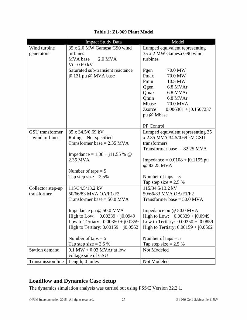
Table 1: Z1-069 Plant Model
Impact Study Data Model Wind turbine generators
35 x 2.0 MW Gamesa G90 wind turbines MVA base 2.0 MVA Vt =0.69 kV Saturated sub-transient reactance j0.131 pu @ MVA base
Lumped equivalent representing 35 x 2 MW Gamesa G90 wind turbines Pgen 70.0 MW Pmax 70.0 MW Pmin 10.5 MW Qgen 6.8 MVAr Qmax 6.8 MVAr Qmin 6.8 MVAr Mbase 70.0 MVA Zsorce 0.006301 + j0.1507237 pu @ Mbase PF Control
GSU transformer – wind turbines
35 x 34.5/0.69 kV Rating = Not specified Transformer base = 2.35 MVA Impedance = 1.08 + j11.55 % @ 2.35 MVA Number of taps = 5 Tap step size = 2.5%
Lumped equivalent representing 35 x 2.35 MVA 34.5/0.69 kV GSU transformers Transformer base = 82.25 MVA Impedance = 0.0108 + j0.1155 pu @ 82.25 MVA Number of taps = 5 Tap step size = 2.5 %
Collector step-up transformer
115/34.5/13.2 kV 50/66/83 MVA OA/F1/F2 Transformer base = 50.0 MVA Impedance pu @ 50.0 MVA High to Low: 0.00339 + j0.0949 Low to Tertiary: 0.00350 + j0.0859 High to Tertiary: 0.00159 + j0.0562 Number of taps = 5 Tap step size = 2.5 %
115/34.5/13.2 kV 50/66/83 MVA OA/F1/F2 Transformer base = 50.0 MVA Impedance pu @ 50.0 MVA High to Low: 0.00339 + j0.0949 Low to Tertiary: 0.00350 + j0.0859 High to Tertiary: 0.00159 + j0.0562 Number of taps = 5 Tap step size = 2.5 %
Station demand 0.1 MW + 0.03 MVAr at low voltage side of GSU
Not Modeled
Transmission line Length, 0 miles Not Modeled
Loadflow and Dynamics Case Setup The dynamics simulation analysis was carried out using PSS/E Version 32.2.1.

© PJM Interconnection 2015. All rights reserved. 28 Z1-069 Gold-Sabinsville 115kV
The load flow scenario and fault cases for this study are based on PJM’s Region Transmission Planning Process and discussions with PJM.
The selected load flow scenario is the 2017 summer peak case (which was derived from case employed for the S57/S58 dynamic evaluation), with the following modifications:
1. Addition of all applicable queue projects prior to Z1-069. 2. Addition of Z1-069 queue project. 3. Removal of withdrawn and subsequent queue projects in the vicinity of Z1-069. 4. Dispatch of units in the PJM system in order to maintain slack generators within limits. 5. Removal of several distant generation units from the dynamic simulation to avoid
initialization problems. 6. In the load flow the Z1-069 was set to maximum power output, with unity power factor at
the collector bus and approximately 1.0 pu voltage at the generator bus.
Generation within the PJM500 system (area 225 in the PSS/E case) and all generation within a 6-bus radius of Z1-069 has been dispatched online at maximum output (PMAX).
Fault Cases Table 2 to Table 6 list the contingencies that were studied, with representative worst case total clearing times provided by PJM. Each contingency was studied over a 10 second simulation time interval. Faults were applied to transmission circuits and transformers connected to the POI or one bus removed (up to two buses removed for delayed (Zone 2) clearing faults).
The studied faults included :
1. Steady state operation 2. Three phase faults with normal clearing time 3. Single phase faults with single phase stuck breaker 4. Single phase faults with delayed clearing at remote end due to primary relaying failure
The one line diagram of the PENELEC network in Attachment 2 shows where faults were applied.
The positive sequence fault impedances for single line to ground faults were derived from a separate short circuit case provided by PJM, modified by PSC to ensure that connected generators in the vicinity of Z1-069 have not withdrawn from the PJM queue, and are not greater than the queue position under study.
Evaluation Criteria This study is focused on Z1-069, along with the rest of the PJM system, maintaining synchronism and having all states return to an acceptable new condition following the disturbance. The recovery criteria applicable to this study are as per PJM’s Region Transmission Planning Process:
© PJM Interconnection 2015. All rights reserved. 29 Z1-069 Gold-Sabinsville 115kV
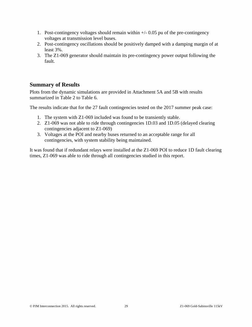
1. Post-contingency voltages should remain within +/- 0.05 pu of the pre-contingency voltages at transmission level buses.
2. Post-contingency oscillations should be positively damped with a damping margin of at least 3%.
3. The Z1-069 generator should maintain its pre-contingency power output following the fault.
Summary of Results Plots from the dynamic simulations are provided in Attachment 5A and 5B with results summarized in Table 2 to Table 6.
The results indicate that for the 27 fault contingencies tested on the 2017 summer peak case:
1. The system with Z1-069 included was found to be transiently stable. 2. Z1-069 was not able to ride through contingencies 1D.03 and 1D.05 (delayed clearing
contingencies adjacent to Z1-069) 3. Voltages at the POI and nearby buses returned to an acceptable range for all
contingencies, with system stability being maintained.
It was found that if redundant relays were installed at the Z1-069 POI to reduce 1D fault clearing times, Z1-069 was able to ride through all contingencies studied in this report.
© PJM Interconnection 2015. All rights reserved. 30 Z1-069 Gold-Sabinsville 115kV
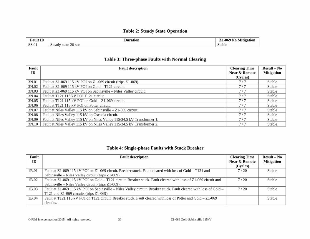
Table 2: Steady State Operation
Fault ID Duration Z1-069 No Mitigation SS.01 Steady state 20 sec Stable
Table 3: Three-phase Faults with Normal Clearing
Fault ID
Fault description Clearing Time Near & Remote
(Cycles)
Result – No Mitigation
3N.01 Fault at Z1-069 115 kV POI on Z1-069 circuit (trips Z1-069). 7 / 7 Stable3N.02 Fault at Z1-069 115 kV POI on Gold – T121 circuit. 7 / 7 Stable3N.03 Fault at Z1-069 115 kV POI on Sabinsville – Niles Valley circuit. 7 / 7 Stable3N.04 Fault at T121 115 kV POI T121 circuit. 7 / 7 Stable3N.05 Fault at T121 115 kV POI on Gold – Z1-069 circuit. 7 / 7 Stable3N.06 Fault at T121 115 kV POI on Potter circuit. 7 / 7 Stable3N.07 Fault at Niles Valley 115 kV on Sabinsville – Z1-069 circuit. 7 / 7 Stable3N.08 Fault at Niles Valley 115 kV on Osceola circuit. 7 / 7 Stable3N.09 Fault at Niles Valley 115 kV on Niles Valley 115/34.5 kV Transformer 1. 7 / 7 Stable3N.10 Fault at Niles Valley 115 kV on Niles Valley 115/34.5 kV Transformer 2. 7 / 7 Stable
Table 4: Single-phase Faults with Stuck Breaker
Fault ID
Fault description Clearing Time Near & Remote
(Cycles)
Result – No Mitigation
1B.01 Fault at Z1-069 115 kV POI on Z1-069 circuit. Breaker stuck. Fault cleared with loss of Gold – T121 and Sabinsville – Niles Valley circuit (trips Z1-069).
7 / 20 Stable
1B.02 Fault at Z1-069 115 kV POI on Gold – T121 circuit. Breaker stuck. Fault cleared with loss of Z1-069 circuit and Sabinsville – Niles Valley circuit (trips Z1-069).
7 / 20 Stable
1B.03 Fault at Z1-069 115 kV POI on Sabinsville – Niles Valley circuit. Breaker stuck. Fault cleared with loss of Gold – T121 and Z1-069 circuits (trips Z1-069).
7 / 20 Stable
1B.04 Fault at T121 115 kV POI on T121 circuit. Breaker stuck. Fault cleared with loss of Potter and Gold – Z1-069 circuits.
Stable

© PJM Interconnection 2015. All rights reserved. 31 Z1-069 Gold-Sabinsville 115kV
Fault ID
Fault description Clearing Time Near & Remote
(Cycles)
Result – No Mitigation
1B.05 Fault at T121 115 kV POI on Gold – Z1-069 circuit. Breaker stuck. Fault cleared with loss of T121 and Potter circuits.
7 / 20 Stable
1B.06 Fault at T121 115 kV POI on Potter circuit. Breaker stuck. Fault cleared with loss of T121 and Gold – Z1-069 circuits.
7 / 20 Stable
1B.07 Fault at Niles Valley 115 kV on Sabinsville – Z1-069 circuit. Breaker stuck. Fault cleared with loss of all Niles Valley 115 kV circuits.
7 / 20 Stable
1B.08 Fault at Niles Valley 115 kV on Osceola circuit. Breaker stuck. Fault cleared with loss of all Niles Valley 115 kV circuits.
7 / 20 Stable
1B.09 Fault at Niles Valley 115 kV on Niles Valley 115/34.5 kV Transformer 1. Breaker stuck. Fault cleared with loss of all Niles Valley 115 kV circuits.
7 / 20 Stable
1B.10 Fault at Niles Valley 115 kV on Niles Valley 115/34.5 kV Transformer 2. Breaker stuck. Fault cleared with loss of all Niles Valley 115 kV circuits.
7 / 20 Stable
Table 5: Single-phase Faults with Delayed Clearing at Remote End
Fault ID
Fault description Clearing Time Near & Remote
(Cycles)
Result – No Mitigation
1D.01 Fault at Z1-069 115 kV POI on Gold – T121 circuit. Delayed clearing at remote end. 7 / 36 Stable1D.02 Fault at Z1-069 115 kV POI on Sabinsville – Niles Valley circuit. Delayed clearing at remote end. 7 / 36 Stable1D.03 Fault at T121 115 kV POI on Gold – Z1-069 circuit. Delayed clearing at remote end. 7 / 36 Unstable
(trips Z1-069)1D.04 Fault at Potter 115 kV on T121 circuit. Delayed clearing at remote end. 7 / 36 Stable1D.05 Fault at Niles Valley 115 kV on Sabinsville –Z1-069 circuit. Delayed clearing at remote end. 7 / 36 Unstable
(trips Z1-069)1D.06 Fault at Osceola 115 kV on Niles Valley circuit. Delayed clearing at remote end. 7 / 36 Stable1D.07 Fault at Mansfield 115 kV on Niles Valley circuit. Delayed clearing at remote end. 7 / 36 Stable
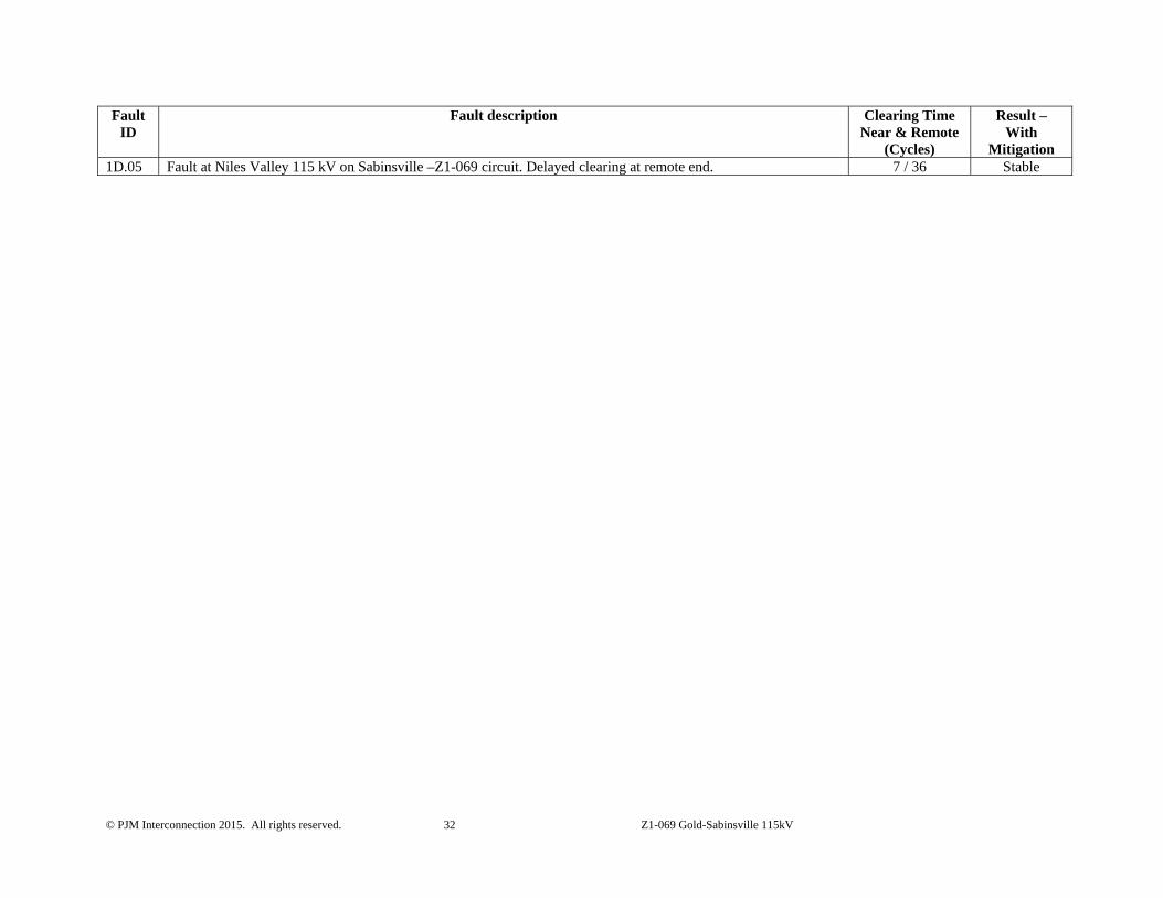
Table 6: Single-phase Faults with Delayed Clearing at Remote End
Fault ID
Fault description Clearing Time Near & Remote
(Cycles)
Result – With
Mitigation 1D.03 Fault at T121 115 kV POI on Gold – Z1-069 circuit. Delayed clearing at remote end. 7 / 36 Stable
© PJM Interconnection 2015. All rights reserved. 32 Z1-069 Gold-Sabinsville 115kV
Fault ID
Fault description Clearing Time Near & Remote
(Cycles)
Result – With
Mitigation 1D.05 Fault at Niles Valley 115 kV on Sabinsville –Z1-069 circuit. Delayed clearing at remote end. 7 / 36 Stable