generator grid connection guide
TRANSCRIPT

A N I N T R O D U C T I O N T O P O W E R S Y S T E M S A N D T H E C O N N E C T I O N P R O C E S S
Generator Grid Connection Guide: An introduction to Power Systems and the Connection Process

G E N E R AT O R G R I D C O N N E C T I O N G U I D E :
Version One 5 May 2008
DISCLAIMER
This document is published by Western Power as an information service. It does not purport to contain all the information that may be necessary to enable a person to assess whether to pursue a particular investment. It contains only general information and should not be relied upon as a substitute for independent research and professional advice.
Western Power makes no representations or warranty as to the accuracy, reliability, completeness or suitability for particular purposes of the information in this document.
COPYRIGHT NOTICE
All rights reserved. This entire publication is subject to the laws of copyright and intellectual property rights. This publication may not be resold or reproduced without the prior permission of Western Power, except as permitted under the Copyright Act 1968.
PREPARED FOR PREPARED BY
Maunsell Limited 47 George Street, Newmarket, Auckland 1023, New Zealand P O Box 4241, Shortland Street, Auckland 1140, New Zealand T +64 9 379 1200 F +64 9 379 1201 www.maunsell.com
May 2008 60025984 © Maunsell Limited 2007

A N I N T R O D U C T I O N T O P O W E R S Y S T E M S A N D T H E C O N N E C T I O N P R O C E S S
Table of contents
1.0 Power system overview 1
1.1 What is a power system? 1
1.2 Key components of large electrical power systems 1
1.2.1 Generators that convert mechanical energy to electrical energy 1
1.2.2 Transformers that prepare for efficient transmission of electrical energy 1
1.2.3 Transmission and distribution lines to carry the power between generation and load 1
1.2.4 Substations where electrical energy can be redirected and modified (reformed) 2
1.2.5 Loads where electrical energy is consumed 2
1.2.6 Auxiliary systems 2
2.0 Generation 3
2.1 Introduction – how a generator works 3
2.2 Generator types 3
2.2.1 Synchronous machines 3
2.2.2 Induction machines 3
2.2.3 Inverter connected 4
2.2.4 Comment 4
2.3 Energy sources / types of generation 4
2.3.1 Thermal Turbines 5
2.3.2 Photovoltaic 5
2.3.3 Wind 5
2.3.4 Cogeneration 5
2.3.5 Water 6
2.3.6 Distributed generation 6
3.0 Power quality issues that may limit the amount of generation that can be connected 7
3.1 Voltage 7
3.2 Frequency 8
3.3 Current 8
3.4 Impedance 8
3.5 Power 8
3.6 Complex power 8
3.6.1 Reactive Power 9
3.6.2 Real Power 9

G E N E R AT O R G R I D C O N N E C T I O N G U I D E :
4.0 Transmission and distribution systems 11
4.1 Why we need different voltages 11
4.2 Transmission circuits 12
4.2.1 What is a transmission circuit? 12
4.2.2 Transmission network types 12
4.3 Lines 14
4.3.1 Overhead line 14
4.3.2 Cable 14
4.3.3 Line/cable comparison 14
4.3.4 HVDC 14
4.4 Substations 14
4.4.1 What are substations for? 14
4.4.2 Substation equipment 15
4.4.2.1 Transformer 15
4.4.2.2 Circuit breaker 16
4.4.2.3 Bus 16
4.4.2.4 Disconnector 16
4.4.2.5 Earth switch 16
4.4.2.6 Instrument transformer 16
4.4.2.7 Surge arrestors 17
4.4.2.8 Reactive power support 17
4.4.2.9 Earthing 17
4.4.2.10 Relay room 18
4.4.3 Substation configurations 18
4.4.3.1 Single busbar (Single breaker per circuit) 19
4.4.3.2 Mesh 19
4.4.3.3 Double busbar 19
4.4.3.4 Breaker and a half (1.5 circuit breaker) 19
5.0 Faults 21
5.1.1 Types of faults 21
5.1.2 Stages of a fault 21
5.1.3 Factors influencing fault currents 22
5.1.4 Fault ratings 22
6.0 Earthing 23
6.1 Introduction 23
6.1.1 What is earthing? 23
6.1.2 Why is it required? 23
6.2 Earthing 23
6.2.1 Transformer and generator earthing 23
6.3 Lightning protection 25
6.4 Surge protection 26

A N I N T R O D U C T I O N T O P O W E R S Y S T E M S A N D T H E C O N N E C T I O N P R O C E S S
7.0 Protection 27
7.1 What is protection? 27
7.2 Why is protection required? 27
7.2.1 system stability 27
7.2.2 Voltage stability 28
7.2.3 Security of supply 28
7.3 Generator protection principles 28
7.3.1 Overcurrent protection 29
7.3.2 Overvoltage protection 29
7.3.3 Low forward power/reverse power protection 29
7.3.4 Unbalanced loading 29
7.4 Protection equipment 29
7.4.1 Fuse 29
7.4.1 Circuit breaker 29
7.4.1 Relay 29
8.0 Operation 31
8.1 Synchronising equipment 31
8.2 Modes of generator operation 31
8.2.1 Frequency control 31
8.2.2 Voltage control 32
8.2.3 Power factor control 32
8.2.4 Islanded operation 32
9.0 Generation/load balance 33
9.1 Swinging generators 33
9.2 Dispatch of generators 33
9.3 Reserve generation 33
10.0 Glossary 35
11.0 Appendix 37
11.1 Explanation of application process 37
11.2 Generator modelling requirements 39
11.2.1 Main Simulation Types 40
11.2.2 The importance of accurate data 42
11.2.3 Additional simulation types 42
11.2.4 Application of studies with respect to the technical rules 42
11.3 Governance of power systems in West Australia 43
11.4 Explanation of relevant legislation and codes 43
11.5 Differences between East and West Australia 45
11.6 Costs to connect 45
11.7 Self evaluations – connection checklist 46

G E N E R AT O R G R I D C O N N E C T I O N G U I D E :
A N I N T R O D U C T I O N T O P O W E R S Y S T E M S A N D T H E C O N N E C T I O N P R O C E S S
PrefaceWelcome to the Generation Grid Connection Guide. This guide provides a high level overview of the issues associated with the connection of a generator to the SWIS. It is intended to assist in understanding the requirements of the Western Power technical rules but does not replace the technical rules.
Power systems are complex. The rules governing connection to the system are, necessarily, highly technical. This document provides background information on aspects of power systems that are particularly pertinent to generators. For readers without a background in the field, it provides a non-technical introduction to the terminology and some of the basic concepts.
It should be noted that this is a highly simplified overview. A fully informed understanding requires significant professional engineering expertise. The physics involved is complicated and generally requires advanced mathematical analysis to gain a full understanding. Most generator proponents will require the advice and services of specialised power system analysis engineers in order to provide required data and meet the requirements for connection. Particularly for a large generator, the connection process can be involved, and the engineering data that must be provided for a full assessment is highly technical. This is because any user of a power system can affect other users. Therefore changes to the system must be carefully assessed to ensure that there will not be adverse consequences and that all users will continue to receive acceptable system performance.
We value your feedback about the format and content of this guide and any additional information you believe we need to take into account. Comments on this document should be sent to:
Manager Network Planning & Development Western Power Corporation GPO Box L921, Perth WA 6842 Telephone: (08) 9326 6293 Facsimile: (08) 92185167 [email protected]
Western Power looks forward to working with you.
Laurie Curro Manager Network Planning & Development Western Power

G E N E R AT O R G R I D C O N N E C T I O N G U I D E :

A N I N T R O D U C T I O N T O P O W E R S Y S T E M S A N D T H E C O N N E C T I O N P R O C E S S
1.0 Power system overview
1.1 What is a power system?
A power system provides a means of harnessing power from energy sources, and transporting the power to areas where it can be used for production and consumption. Three factors motivate the use of large electric power systems:
1. The conversion of mechanical power to electrical power is relatively efficient, and the transport of electricity over long distances is cheap, efficient, and convenient (it is usually better to move the electricity than to move the fuel). Electricity is therefore an effective form in which to transport energy.
2. Electrical power is convenient for many end-uses.
3. Large power systems have significant efficiencies of scale that bring both economic and technical benefits. For instance:
• thecheapestfuelsourcecanbeusedevenwhenitisfarfromtheload;
• reserveplantcanbesharedamongmanyusers,allowingamorereliablesupplytobeprovidedatlowercost;
• inalargesystem,thefrequencydisturbancefromtheaccidentalshutdownofapowerstationissmallerthan for the same shutdown in a small system.
1.2 Key components of large electrical power systems
1.2.1 Generators that convert mechanical energy to electrical energy
Generators convert energy from a mechanical source (such as a diesel engine) into electrical energy.
1.2.2 Transformers that prepare for efficient transmission of electrical energy
The voltage of the electrical energy is then increased using a step up transformer that allows the energy to be transported long distances to where it is required, with reduced losses. The losses are proportional to the square of the current. Increasing the voltage reduces the required current to provide the same power.
Transformers often have manually or automatically operated tapchangers that allow the voltage level on one side of the transformer to be adjusted relative to the other side. Compared with synchronous generator voltage control, this is a relatively slow and coarse mechanism.
1.2.3 Transmission and distribution lines to carry the power between generation and load
The energy is transferred at high voltage from one geographical area to another using transmission lines. Using high voltage reduces power losses in the lines. At high voltage the lines require a lot of insulation (large air gaps if overhead) to stop the energy from bypassing the area it is required.
The almost universal use of rapidly alternating voltage allows the voltage level to be changed easily using transformers, but means that the energy delivered on an individual line also alternates. Large power systems therefore use three separate lines (called phases) so that the individual fluctuations cancel out and a steady power can be delivered. This also allows the sizes of motors and transformers to be smaller (for the same power delivery) and allows less copper to be used in the lines (for the same power delivery).
PA
GE
1

G E N E R AT O R G R I D C O N N E C T I O N G U I D E :
Large generators (and large loads) have three output (or input) phases to match this system.
Traditionally, the direction of power flow on bulk transmission networks has been unpredictable. Like a freeway system, high capacity must be provided for flows throughout the network.
By contrast, distribution networks historically have only served loads. The power flow direction has been predictable, and the required capacity is smaller towards the ends of the network. A tree structure is natural, like a road feeder network.
In recent times, distributed generation has become more common, with large quantities of small generation being connected directly to the distribution network. Connection of generators directly to the distribution network is making it increasingly difficult to predict the power flow through the network, and many existing networks require modification to cater for the new generation sources.
1.2.4 Substations where electrical energy can be redirected and modified (reformed)
At each end of a transmission line there are switching stations (also called substations) that can direct the energy where required and allow lines to be taken out of service when necessary. If there is large demand for energy close by, the voltage may then be stepped down using a supply transformer. The lower voltage level is suitable for distribution of the energy over moderate distances to central points of residential, commercial and industrial load.
1.2.5 Loads where electrical energy is consumed
After the energy is stepped down from transmission voltage, the energy feeds out to local street supplies, where the voltage is further reduced to a level directly usable by consumer loads.
Industrial and some large consumer loads may use the energy distributed over three phases. However, most small consumer loads use the energy from a single phase, and are balanced evenly between all three phases.
1.2.6 Auxiliary systems
In order to ensure the effective operation of the key primary systems described above, various secondary systems are necessary to provide control and monitoring functionality and to deal appropriately with equipment problems, particularly power system faults
PA
GE
2

A N I N T R O D U C T I O N T O P O W E R S Y S T E M S A N D T H E C O N N E C T I O N P R O C E S S
2.0 Generation
2.1 Introduction – how a generator works
A generator has an input shaft that is driven by a ‘prime mover’ such as a diesel engine, or a steam, wind, or water (hydro) turbine. The prime mover supplies mechanical energy to the generator input shaft. Inside the generator,
• theinputshaftturnsarotor that creates a rotating magnetic field.
• thisfieldcrossesstator (fixed or static) windings (wire coils) in the generator housing. These windings are connected to the generator output
• thechangingmagneticfieldcreatesavoltageonthegeneratoroutputbytheprocessofmagnetic induction.
when the generator output is connected (through a transmission system) to a load, currents flow that carry electrical energy to the load
2.2 Generator types
Electrically, there are two main types of generator in common use on power systems: synchronous generators and induction generators. Most generators are synchronous generators. Electric motors are available in corresponding forms, however synchronous motors are rare and used only in special applications.
2.2.1 Synchronous machines
A synchronous machine as indicated by its name requires the rotor to spin at a fixed speed relative to the frequency of the power system. The rotor spinning frequency can be equal to that of the power system (3000 RPM in Australia), or can be reduced to a fraction of the frequency (to give, for instance, 1500 RPM or 750 RPM) by adding additional sets of coils in each phase in the stator. These coils are called poles. The turbine (or prime mover) can spin at other, fixed speeds (e.g. 6300 RPM) if a mechanical gearbox is used to change the speed to one that a synchronous machine accepts.
The rotor has a winding that is powered by a steady (direct current) power supply and the constant current forms a magnetic field, which rotates with the rotor. A synchronous generator can control its output voltage by changing the amount of current fed into the rotor winding. Historically, this has generally been the cheapest way to provide fast voltage control on power systems, and so almost all generators (and all large generators) have been of the synchronous type.
2.2.2 Induction machines
Induction machines are not speed-locked to the system frequency, although in normal operation they operate within a small speed range. Their chief advantage is that they are mechanically simpler, and cheaper to manufacture. However they have adverse effects on power system performance (compared with synchronous machines, or other types of load).
Squirrel Cage
The squirrel cage induction machine is named because of the use of a cylindrical rotor cage inside the rotor, which looks somewhat like cage that squirrels exercise on (or in the southern hemisphere a mouse wheel).
The rotor does not require a power supply to maintain a magnetic field. Instead the coils in the armature induce currents to flow along the rotor bars, and a resulting magnetic field forms. The rotor is very tolerant to changes in
PA
GE
3

G E N E R AT O R G R I D C O N N E C T I O N G U I D E :
speed because the magnetic field present on the rotor is not ’held in place’, as by an external power supply in a synchronous machine.
Doubly Fed Induction Generator (DFIG)
A Doubly Fed Induction Generator behaves something like a mixture of a normal induction machine (like the Squirrel Cage) and a synchronous machine. Inverter fed, three phase windings on the rotor as well as the stator allow the magnetic field of the rotor to rotate independent of the mechanical rotation. This allows the rotor field to remain aligned to the field of the power system frequency in the armature, while the rotor speed varies.
A DFIG is very useful in wind generation, as the blades can spin at a range of speeds. The aerodynamic efficiency of wind turbines is greatest at a particular rotation speed, and the optimal speed varies when the wind speed changes. Therefore variable speed operation maximises the efficiency of the wind capture. In addition this type of generator can help to control system voltage (unlike a squirrel cage induction machine). Usually the inverter is only small (relative to the machine size) and so the speed range and amount of voltage support are both limited.
2.2.3 Inverter connected
An inverter is an electronic device that can output an alternating current, from a direct current input or from an input that is oscillating at a different frequency. This allows a source that produces direct current (such as a photovoltaic system) to be connected to the power system (which uses alternating current).
Another application is to allow a synchronous machine to be operated at variable speed. Compared with a doubly fed induction generator, a mechanically simpler arrangement can be used (by avoiding the use of high power slip-rings), however the inverter cannot have a smaller rating than the main machine output.
Inverters can provide excellent voltage control, even when the energy source is unavailable.
2.2.4 Comment
In practice, most generators on power systems are synchronous (and regulate voltage), and most loads are induction motors (with the remainder being resistive or static). It would be possible in principle to reverse this and have a power system with induction generators, and synchronous motor loads (with the loads regulating voltage). It could even be argued that this is preferred, since it is the load voltage that is of most interest and so it is better that the regulation occurs near the load.
However there are few generators, and very many loads. It is, generally, cheaper and more efficient to provide the expensive (and somewhat complicated) voltage control equipment on the small number of generators. In principle it is not necessary to provide this control on every generator (and there have been proposals in the technical literature to use large, induction generators), however this has not eventuated in practice.
Many early wind generators used induction machines (which are cheaper, and, importantly, require a lighter, mechanically simpler, and less maintenance-intensive machine in the turbine nacelle). This was acceptable while the machines and wind farms were relatively small but they are now approaching or exceeding the size of conventional powerplants. Given the circumstances outlined above, it is not surprising to find that over time, induction generators are increasingly being required to install supplementary voltage control equipment to overcome the inherent limitations of the generators.
2.3 Energy sources / types of generation
The quality of power available through a power system not only depends having an adequate amount of generation present, with a suitable reserve margin, but also the type of energy source used for the generation. It is important to model the physical control of the energy source when considering the effect the generator will have on system stability. In some cases the design of a generating unit can be tailored to suit the stability characteristics required on the system.
PA
GE
4

A N I N T R O D U C T I O N T O P O W E R S Y S T E M S A N D T H E C O N N E C T I O N P R O C E S S
2.3.1 Thermal Turbines
The energy source for thermal generation can be fuels such as coal, gas, biomass, or any material that can be burnt to produce heat energy, or other heat sources such as nuclear, geothermal, or (experimentally) solar-thermal energy. For steam-turbines, the stored energy in the source is used to heat water to generate high pressure, high temperature steam that is passed through a set of turbines. The turbine sets convert heat energy into rotational energy. The waste steam is then condensed and the water returned to the boiler where the cycle continues. Gas turbines do not use an intermediate stage of water heating and instead directly pass the hot, high pressure combustion gasses through a series of turbine blades. For increased efficiency, combined cycle turbines use an initial gas turbine stage, with the exhaust gas then used to heat water to feed a steam turbine.
Steam turbine thermal generation generally requires a significant amount of time to ramp up to full power output after an initial start, due to the time taken to raise the equipment to operating temperatures. After operating at constant output for some time, it can take time to respond to a signal to ramp the power output up or down. This limits the ability of steam thermal generation to pick up extra load that appears with little warning.
2.3.2 Photovoltaic
Photovoltaic generation involves converting energy from the light spectrum directly into electrical energy through the use of semi-conducting materials. Photovoltaic generation produces power in direct current (DC). This means the current does not alternate direction at 50 cycles a second, as in conventional alternating current (AC) generation. An inverter is used to connect to the power system.
The inverter can provide fast voltage control, even at night when the sun is unavailable. The output from photovoltaic has the advantage that the output is likely to be available during system peak loads as our peak load is generally driven by temperature.
2.3.3 Wind
A ‘wind farm’ is typically made up of numerous turbine sets distributed over a moderate geographical area that each produce a small amount of power, in the order of 0.5-2MW.
Wind generators are a renewable fuel source, and only cost as much as initial capital expenditure and maintenance.
Wind generation has a variable output based on wind speed so cannot be scheduled using conventional techniques. This is a particular issue when the portion of wind generation is high, relative to the total generation pool. Provision is required for other types of generation to step in should the wind speed and resulting power output fall unexpectedly.
Traditionally wind farms use induction generators however these will no longer meet the requirements of the technical rules unless they have significant reactive support.
Wind farms that use doubly fed induction machines can provide voltage control although often within a limited range, and may not require additional reactive support to meet the requirements of the technical rules. Inverter connected machines should in principle be able to provide full voltage control even when the wind is unavailable but to date commercially available machines have generally not done so.
2.3.4 Cogeneration
Industrial or commercial plants with a requirement for steam/hot water now often include generating plant utilising or producing steam to improve overall economics, as a Cogeneration or Combined Heat and Power (CHP) scheme.
PA
GE
5

G E N E R AT O R G R I D C O N N E C T I O N G U I D E :
The plant will typically have a connection to the public utility system and such generation is referred to as ‘embedded’ generation. The generating plant may be capable of export of surplus power, or simply reduce the import of power from the Utility.
A cogeneration scheme directly coupled to the plant heating system has limited ability to vary its electrical output to meet power system needs without varying the heat output to the rest of the plant. The scheme can have an auxiliary firing system fitted to allow the generator to have maximum electrical output even when the plant heat demand is low, increasing the flexibility of power supply.
2.3.5 Water
Hydro generation converts potential energy into electrical energy using a water turbine connected by a shaft to the generating unit. The turbine can be designed for generation with differing levels of waterhead. The responsiveness of the generating unit to change power output varies significantly with the design of the turbine and penstock unit.
Hydro generation is generally quicker to respond to a requirement to suddenly increase output than thermal generation and can also come on line much faster.
2.3.6 Distributed generation
Distributed generation involves the connection of small generation on the distribution network in areas close to load centres. The power generated by distributed generation often is consumed on the network to which it is connected, without being increased in voltage for transmission over long distances.
Existing distribution networks have been developed in an environment where distributed generation was rare and small. There design has taken advantage of simplifications that this allows (such as tapering the capacity towards the end of the network, low fault ratings, and the use of much simpler control and protection systems than are used on transmission networks). Connecting large amounts of generation to existing distribution networks (designed under different circumstances) is often problematic. Distribution connected generation has safety issues in ensuring adequate clearance of faults as well as issues associated with the voltage profiles, conductor ratings and fault ratings.
Obtained from Areva Protection guide.
PA
GE
6
A N I N T R O D U C T I O N T O P O W E R S Y S T E M S A N D T H E C O N N E C T I O N P R O C E S S
3.0 Power quality issues that may limit the amount of generation that can be connected
The power system needs to run in a stable state and be able to deliver power to consumers at an acceptable quality. All connected equipment must operate in the desired manner.
The correct operation of a network requires the voltage to stay within an operational range, which all electrical equipment is designed to handle. Broadly, the essential qualities are listed below:
• sinusoidalwaveform,withalowlevelofdisturbances(frommotorstarting,harmonicsetc.)
• aconstantpowersystemfrequencyof50Hz
At times of heavy loading on the power system, the current through any piece of equipment should not be above its design rated level. During a fault all equipment should be able to handle the current flowing to the fault point.
The impedance of generators, transformers, and transmission circuits should be low enough to allow power to flow to where it is required without excessive voltage drop from generation to load. The impedance should be sufficient to ensure that the fault current on any one piece of equipment will not be excessive.
A new generator has the responsibility to ensure that they can output power over their full output range, while meeting the power quality requirements of the technical rules.
3.1 Voltage
The voltage the grid is designed to operate at is referred to as nominal voltage. Nominal voltage can also be referred to as 1 per unit (pu) or 100 per cent (of nominal voltage). When a point at the grid is operating at 1.05pu or 105 per cent, this means that the voltage measured at that point is 5 per cent higher than the nominal voltage.
The voltage varies on a power system depending on the size and location of loading, and the route the power has to travel from generation to load.
Normally, if the voltage at any point on a network rises above 110% or drops below 90%, the quality of power delivered is unacceptable as it may cause damage to connected equipment.
Closer to the power consumer, the range of acceptable voltage variation during normal operation decreases to plus or minus 6 per cent.
Transformers play a vital role in voltage regulation by changing their voltage conversion ratio (tapchanging) depending on loading conditions of the system to keep the system within voltage limits. Transformers take time however to change taps, and are not able to smooth out surges and other short term voltage variation.
The quality of power transfer on a network may also be poor if the voltage varies erratically. The most common problems are:
• Flicker – Large loads connected to the network that vary or switch regularly can cause small voltage variations on the surrounding network. These cause brightness of incandescent lights to change, which is irritating to users.
• Dips – Starting a large motor on a weak network can cause a large voltage dip, which can last up to 10 seconds. A dip in voltage can cause other loads connected nearby to switch off, or in severe cases damage.
• Harmonics – The connection of large variable speed drives to a network introduces power noise onto the surrounding network, called harmonics. The current flow caused by these harmonics can cause other electrical devices to overheat. The prolonged presence of harmonics on a system will shorten the life of sensitive equipment.
PA
GE
7

G E N E R AT O R G R I D C O N N E C T I O N G U I D E :
• unbalance – Unequal loading on each of three phases of the power system will cause the network to be unbalanced. In this situation, machines that run on three phases for consistent power output will have fluctuating power output at the same rate of the system frequency. This can cause mechanical damage to motors, and also damage sensitive electrical equipment.
3.2 Frequency
The frequency of the power system directly relates to the rotational speed of machines connected to the power system. The frequency needs to be maintained to avoid damage to motors. If the frequency drops, generation must be increased to bring the frequency back to normal levels. Generation needs to be able to run over the full range of allowable network frequency, as the unscheduled trip of a generator can decrease system stability.
3.3 Current
The current flowing through a given circuit in the network should not exceed the rating of connected equipment. Currents above the rated current can cause equipment to suffer excessive mechanical stress and overheat (which may result in permanent damage).
A fault at some point along a circuit can cause large currents to flow in the network to the fault point. The equipment surrounding the fault needs to be capable of handling large currents without overheating until protection can isolate the supply of power to the fault.
3.4 Impedance
The impedance of an electrical circuit needs to be low enough that the generator can supply the maximum desired export power without causing the voltage to drop too low at either end.
Occasionally, when new generation is connected to strong points on the network, additional impedance may be required to prevent the fault contribution of the generator from exceeding the fault ratings of nearby network equipment.
3.5 Power
Occasionally on a power system there are limits placed on generator power output. This may occur during the outage of an electrical circuit which helps transfer from the generator, or also when voltages on the system reach the limits of allowable range.
Typical operating constraints are normally discovered before a new generator is installed by simulating a range of operating scenarios with proposed generation. If limits are considered too constrictive other electrical equipment can be installed to increase the range of operation.
3.6 Complex power
Complex power is the combination of the power required to enable power transfer across a power system (the reactive, or imaginary part) and the useable power being transferred from generation to load (the real part). The real and reactive power parts are discussed separately as they behave differently on the power system.
PA
GE
8
A N I N T R O D U C T I O N T O P O W E R S Y S T E M S A N D T H E C O N N E C T I O N P R O C E S S
3.6.1 Reactive Power
Reactive (or imaginary) power provides the force that enables power transfer across the power system. In other words, it supports the voltage necessary to drive real power through the electrical circuits to the areas of load. Transformers and many motors absorb reactive power, and use it to establish a magnetic field, allowing energy to flow through the magnetic coupling. Generators and capacitors produce reactive power, and their output is balanced to meet total reactive demand on the power system. Generators can provide a variable level of reactive power by changing the excitation of the rotor, and can provide continuous voltage control with the help of voltage monitoring control circuits. Capacitors are fixed devices that can switch in blocks to provide a set level of reactive power and are used to boost the voltage.
Reactive power support is required to stabilise the voltage. If there is insufficient reactive power the voltage will reduce. If the shortfall is great enough it will lead to voltage collapse.
If there is too much reactive power provided then there are issues with over voltages. This is a particular problem with long lightly loaded lines.
3.6.2 Real Power
Real power is the power available on a power system to be converted by loads into other forms of energy. The real power output of generation must be balanced by the power consumed by loads and losses. If the generation is greater than the energy used then the frequency will increase. If the generation is less than the energy used then the frequency will fall. To maintain a constant power system frequency the generation must be exactly matched to the loads and losses.
PA
GE
9

G E N E R AT O R G R I D C O N N E C T I O N G U I D E :
PA
GE
10

A N I N T R O D U C T I O N T O P O W E R S Y S T E M S A N D T H E C O N N E C T I O N P R O C E S S
4.0 Transmission and distribution systemsIn road networks, a range of designs are used depending on the circumstances. Freeways allow many cars to travel at once, with many lanes (so that travel is still possible even if a lane is closed due to an accident or maintenance), and with no interruption from traffic controls. Smaller regional roads that feed into and out of the freeways have traffic lights and lower carrying capacities. In the suburbs, lanes are even narrower and stop signs are common.
Power systems have similar characteristics. A useful distinction is between transmission and distribution subsystems. Typical characteristics are as follows:
Property Transmission Distribution
Voltage level Extremely High (66,000 Volts up to 330,000 Volts or more)
High (22,000 Volts) and Low (415 V and 240 V)
Degree of redundancy High (backups provided) Lower (Backup limited)
Structure Meshed (Alternate paths always in service)
Radial (Branching and tapering, l ike a tree)
Transfer levels High (tens to hundreds of MW or more) Lower (ten MW or less)
Protection High speed, sophisticated (unit or distance), duplicated
Slower, simpler (overcurrent and earth fault), limited or remote backup
Number of connections Low (less than ten) Very high (hundreds)
Neutral No neutral Neutral may be present
Earthwire Overhead earthwire commonly used Underslung or (usually) no earthwire
4.1 Why we need different voltages
Low voltages are used in general low power applications as they hold a sufficient amount of energy for most consumer needs, whilst not being too destructive during a fault
Medium voltage and relatively high current is used in generation and loads to enhance the magnetic coupling (allowing the conversion of large amounts of power between mechanical and electrical form).
High voltage is used in distribution to allow bulk power to be distributed moderate distances with relatively little voltage drop. Distribution voltages allow economic plant configurations to be deployed over a wide area where a large number of equipment items need to be deployed. A relatively higher level of losses is tolerated to save on capital cost.
Extra high voltage is used in transmission to allow a high level of power transfer per ampere of current flowing through the line. As line losses are proportional to the square of the current and are not influenced by an increase in the system voltage, power can be transferred more efficiently, with fewer losses over the length of the transmission line per MW transferred. This means that at a higher system voltage more power can be transferred for the same conductor size, which makes extra high voltage systems more economical for transferring large amounts of power.
Transmission lines operating at extra high voltage form the backbone of a large power system, and are able to transfer large quantities of power over large distances, without losing excessive amounts of power in losses.
PA
GE
11

G E N E R AT O R G R I D C O N N E C T I O N G U I D E :
4.2 Transmission circuits
4.2.1 What is a transmission circuit?
A transmission circuit is a connection between two points (sometimes three) to allow the transfer of electrical energy. One circuit for a three-phase alternating current power system will have three conductors.
There is an advantage to have two points connected by more than one electrical circuit together, as this avoids loss of supply (or blackout) if one circuit has a fault or is out of service for maintenance.
A transmission circuit may be overhead or underground or a combination of both.
4.2.2 Transmission network types
The transmission system is constructed to provide an economic and reliable link between the generation and the load centres.
Transmission System
Sub-transmission systems distribute the power from load centres or “points of supply”, to the specific local area substations (also called zone substations) where the power is further distributed.
Large power consumers, such as industrial sites or large commercial sites may require their own zone substation, in which case they have a dedicated sub-transmission connection to their premises.
PA
GE
12

A N I N T R O D U C T I O N T O P O W E R S Y S T E M S A N D T H E C O N N E C T I O N P R O C E S S
Distribution systems distribute the power from zone substations to roadside substations or other local reticulation, which forms the final link to bring the power down to a voltage level where it is safe to use. Mostly these systems are radial from each zone substation with an open point between feeders of adjacent networks to allow transfer of loads between adjacent points of supply
Local reticulation inside customer sites may be as simple as an LV service main from a distribution transformer to the customers Main Switch Board (MSB), or it may be a combination of HV and LV meshed reticulation providing multiple supplies and embedded generation.
Typical sub-transmission system
Typical distribution system
PA
GE
13

G E N E R AT O R G R I D C O N N E C T I O N G U I D E :
4.3 Lines
4.3.1 Overhead line
An overhead transmission line uses steel towers or wooden, concrete or metal poles that hold the conductors at a safe distance above ground to avoid a short circuit (or fault).
Between the cross arm installed on the pole or tower and the electrical conductor, there are a stack of insulators, that prevent current from flowing to the pole (and on to the ground).
4.3.2 Cable
A cable surrounds each electrical conductor with an insulating material and a grounded conductive screen. This allows the cable installed in buildings or directly in the ground without letting the conductor short circuit.
4.3.3 Line/cable comparison
Property Overhead line Cable
Ease of installation Simple Difficult
Transmission over long distances Good Poor
Use indoors, and in highly populated areas Difficult Very Good
Visual impact High None
Reliability Good Very good
Complexity of repair Simple Difficult
Cost of material Low Very high
Cost of installation Low Very high
4.3.4 HVDC
HVDC stands for High Voltage Direct Current, and is useful for the transmission of large amounts of power over long distances. Complex equipment is required for the installation of an HVDC circuit, and does not compete economically with an Alternating Current (AC) transmission line over short distances.
4.4 Substations
4.4.1 What are substations for?
A substation is a point on the power system that connects multiple circuits and may also change the voltage to more useable levels. The common uses for a substation are listed below:
• connectionofageneratortoatransmissionnetworkbymeansofastep-up transformer.
• connection of a customer network by means of a step-down transformer.
• the ability to share power between multiple electrical circuits.
• in the event of a fault on a connected circuit, substations can clear the fault and re-distribute power accordingly, therefore minimising disruption to power supply.
• planned disconnection of circuits to allow maintenance to occur on power system equipment, without disrupting power supply.
PA
GE
14

A N I N T R O D U C T I O N T O P O W E R S Y S T E M S A N D T H E C O N N E C T I O N P R O C E S S
A substation may consist solely of a transformer and two switches, and be mounted on a pole. A main substation on a particular network however is more likely to be a site complete with control room, indoor and/or outdoor switchgear and transformers.
4.4.2 Substation equipment
4.4.2.1 Transformer
Transformers allow the voltage level of a network to be increased to transfer large amounts of power over long distances, and then bring the voltage level back down to a level useable by consumers.
Transformersservetwopurposes:theycantransferpoweracrosstwosystemsofdifferentvoltages;and/ortheycan provide electrical isolation between electrical systems.
A 2-winding transformer can connect a network of one voltage level to the primary winding, and one network to the secondary winding. Transformers commonly contain all 3 phases in the same enclosure, so there are 3 primary windings (one for each phase), and 3 secondary windings.
The ratio between the number of turns on the primary and secondary windings determines the voltage conversion ratio.
As transmission voltages can vary depending on network loading, the voltage conversion ratio of a transformer can be fine-tuned using a tap changer. A tap changer can increase or decrease the number of turns on one side of a transformer to change the voltage conversion ratio. The significance of this is that the voltage of the primary network can vary while the transformer regulates the voltage of the secondary network.
The electrical isolation between the primary and the secondary network is achieved by having no direct electrical connection between the conductors on the primary and secondary sides. Furthermore, the magnetic coupling resists changes in the amount of current flowing (presented as an impedance), which limits the magnitude of fault current.
There are three main types of transformers that are used for power transfer between transmission networks.
Generator step-up (or generator transformer) – a generator transformer is made to accept the large currents generated at medium voltage and transfer the power to the transmission system at a high voltage level, and relatively low current. Generator transformers typically have a large voltage ratio and have a delta connection on the generator side to limit the flow of zero sequence current.
Interconnection transformer– an interconnection transformer transfers power between transmission networks of different voltages. These transformers have a small voltage ratio.
Step-down transformer – a step-down transformer reduces the voltage from one level to another. There are two main categories for step down transformers:
• supply(zonesubstation)transformer–thisstepsthevoltagedownfromtransmissionorsub-transmissiontodistributionvoltagelevels;and
• distributiontransformer–stepsthevoltagedownfromdistributionhighvoltagetolowvoltage.
Other types of transformers are used in the power systems such as earthing transformer, current transformers and voltage transformers
PA
GE
15

G E N E R AT O R G R I D C O N N E C T I O N G U I D E :
4.4.2.2 Circuit breaker
Circuit breakers (commonly abbreviated as CB), are switches which are used commonly in Substations that are capable of breaking fault current. In the event of a fault, circuit breakers can be switched very rapidly to minimise the amount of damage that occurs at the fault location and all connected equipment as well as minimising the disturbance to customers.
During fault conditions, it is likely that large currents (possibly due to a short circuit) will flow through the circuit breaker. The circuit breaker needs to be designed to be able to open the switch (or break the connection) during this maximum current flow, in order to successfully clear the fault.
4.4.2.3 Bus
The bus describes the electrical conductor that connects all the circuits together in a substation. It allows the current from any connected circuit to flow to any other circuit. The current flow through the bus cannot be directly controlled, however the switching of equipment can change the current flow. Different bus configurations are used in different circumstances. These are discussed further in section 5.4.3
4.4.2.4 Disconnector
Disconnectors provide a visible electrical isolation gap between two points on an electrical network.
If maintenance was required on a transmission line, theoretically it would be sufficient to open the circuit breakers at each end, and connect a connection to earth on each side of the maintenance crew for safety. However, circuit breakers do not show a visible break in the network, and do not adequately demonstrate to local personnel that a section of the network is isolated.
Disconnectors can also allow the quick reinstatement of all non-faulted equipment after a fault has occurred. This is specifically important when dealing with circuit breaker failure.
Furthermore, disconnectors provide a mechanism for isolating both terminals of the circuit breakers so that maintenance can be carried out on the circuit breaker itself.
4.4.2.5 Earth switch
An earth switch allows the earthing of parts of a circuit, as a safety precaution during maintenance. The earth switchwillprotectagainstinadvertentre-liveningofanelectricalcircuitduringmaintenance;andwillprovideapath for any stray currents that may flow if the circuit is in close proximity to other live circuits.
4.4.2.6 Instrument transformer
Instrument transformers form the eyes and ears of the power system. These devices allow the safe measurement of current and voltage present on the main conductors. As indicated by the name, these measurement devices transform the electrical property they are measuring down to a level suitable for input into electronic devices as well as insulating the measuring devices from the power system. These devices feed information to relays which monitorthesystem;andtothenetworkoperator,sotheycanmanagethepowerflow.
Voltage transformer
A voltage transformer operates similarly to a step-down power transformer, in that it reduces the voltage from any system voltage (i.e. 6.6kV – 330kV) down to around 110V. However the main difference with a voltage transformer is that it is not designed for power transfer, and is only designed to transfer the minimum amount of power necessary to make an accurate voltage measurement (typically 100-200VA).
PA
GE
16

A N I N T R O D U C T I O N T O P O W E R S Y S T E M S A N D T H E C O N N E C T I O N P R O C E S S
Current transformer
A current transformer generally uses the primary conductor as the non primary winding. It uses a secondary coil that is would around a toroidal core that is positioned around the main conductor to measure the current. The numberofturnsofthesecondarycoildeterminesthecurrentreductionratio;theratioischosentoreducenormaloperating current down to a level that protection equipment can use to make measurements.
An open circuit of the secondary winding of a current transformer is very dangerous as the secondary winding of a current transformer acts as a current source. This means that the secondary winding would try to ‘drive’ the current through whatever material that forms the open point of the circuit. It could deliver a fatal level of current to personnel in close proximity, as well as damaging the insulation on the secondary of the current transformer.
4.4.2.7 Surge arrestors
Surge arrestors are a form of ‘pressure release’ for a power system. They allow current to flow to earth through them if the voltage becomes too high. Surge arrestors are very useful at preventing equipment damage due to lightning strikes, switching surges, and other unexpected over-voltages that can occur.
A surge arrestor is not the same as a short circuit, as when it allows current to flow to earth it does not reduce the voltage level of the connected electrical network below its nominal operating value.
4.4.2.8 Reactive power support
Reactive power gives the power system the voltage support it needs to transfer real power from generation to loads.
Reactive power support can be installed at any point on a network (although substations are commonly chosen) to help stabilise the surrounding network and ensure normal operation. Common types of reactive power support are listed below:
Capacitor bank – At times of large loading on a power system at points that are distant to generation, the voltage can drop to undesirable operational levels, and in extreme cases lead to unplanned load tripping. The net effect of installing capacitors is a boost in voltage, and helps alleviate voltage sag during heavy loading.
This is caused by a decrease in the reactive power flow in the supply circuit, and a subsequent reduction of the voltage drop along the length of the circuit.
Shunt reactor – A shunt reactor can be required to prevent over-voltages from occurring at parts of the network, either during periods of light loading or when a supply point in the network rises with the export of large volumes of power.
Static Var Compensator (SVC) – An SVC allows a variable amount of reactive power to be supplied or consumed which is consequently used to control the voltage of a point on the network to a desired level over a range of different operating scenarios.
An SVC employs the use of heavy duty electronic switches, which switch many times a second to regulate the amount of reactive power produced or consumed.
4.4.2.9 Earthing
At most substations all equipment with metallic parts, which are not part of the main electrical circuit, are earthed to ensure safety and provide a common reference for the power system.
At large substations the physical connection to the ground is usually made by buried copper conductors connected together in grid like fashion. In smaller installations or for transmission poles the earthing connection can consist of a single pin driven into the ground.
See section on earthing for more information.
PA
GE
17

G E N E R AT O R G R I D C O N N E C T I O N G U I D E :
4.4.2.10 Relay room
The control room contains the ‘brains’ of a substation. The control room has three essential roles to ensure the substation is operated reliably and safely:
1. to allow an operator to locally control the operation of switching equipment, during maintenance, or to reinstate a circuit following a fault.
2. to house the protection that automatically switches circuits out of service if a fault is detected.
3. communication of the current status of the substation (switches open, warnings and alarms, etc.) using a SCADA system.
As the power supply to the control room is essential for managing the flow of power through the substation, there are back-up battery power supplies to maintain operation for a sufficient amount of time during a conventional power outage.
Substation control
Substation control allows the operation of equipment within the substation by operators. If maintenance is required on a piece of equipment, an operator can switch out sections of the substation to make the equipment safe to work on, while maintaining power supply to consumers.
If there is a fault on a circuit connected to the substation, the protection will automatically disconnect the faulty equipment. An operator may then reconfigure the network to restore supply.
Protection
The role of protection is to initiate the operation of a circuit breaker to clear a fault at or near the substation as quickly as possible to minimise damage to equipment, people, and loss of power to consumers. More information on the role of protection is available in the protection section.
Communications
A substation has communications equipment installed so the status of the power flow through multiple substations can be observed from a central operating room. This allows the power system to be monitored as a whole – and plays a vital part in the dispatch of generation, and allocation of sufficient reserve capacity on the power system. A SCADA interface forms the main backbone of the power system communications system (see explanation below).
Communication is also used to aid the operation of protection equipment.
SCADA system
A Supervisory Control And Data Acquisition System (SCADA) consists of a software package that collects real time data from the communications interface of relays, alarms and control systems. The SCADA system allows a system operator to get an overview of the system health from a centralised location – without having to visit the substation.
4.4.3 Substation configurations
Different substation configurations are used for substations with differing levels of importance. For a 330kV bus, Western Power requires a minimum of a mesh configuration to provide some security against a bus fault occurrence in order to meet the reliability requirements of the technical rules. A mesh configuration is not readily expandable and so if the site is likely to have more than six switches, a breaker and a half configuration is used.
PA
GE
18

A N I N T R O D U C T I O N T O P O W E R S Y S T E M S A N D T H E C O N N E C T I O N P R O C E S S
4.4.3.1 Single busbar (Single breaker per circuit)
The single busbar arrangement is simple to operate, places minimum reliance on signalling for satisfactory operation of protection and facilitates the economical addition of future feeder bays.
A single busbar arrangement generally will have a circuit breaker present on each connected circuit, which will protect the substation from outage during an external fault. However, a bus fault will cause a complete outage of the substation until the cause of the fault can be resolved.
A single busbar arrangement can have extra security of supply by installing a bus section breaker. A bus section breaker will split the bus into two sections, allowing half the bus to continue operating following a bus fault on either section.
4.4.3.2 Mesh
A substation with a mesh configuration utilises four circuit breakers to control four circuits. The scheme offers better features and facilities than the single busbar without a bus section breaker. However it cannot easily be expanded, beyond the original design, in the event that additional circuits are required.
4.4.3.3 Double busbar
A double busbar arrangement allows for the connection of each circuit to either of two busbars (bus ‘A’ or bus ‘B’) using busbar selector disconnectors. In the event of a fault on either busbar, each circuit can be rapidly switched across to the other busbar, with minimum disruption.
4.4.3.4 Breaker and a half (1.5 circuit breaker)
A breaker and a half configuration uses three circuit breakers to connect two circuits (or 1.5 circuit breakers per circuit). This arrangement offers the benefits of a double busbar arrangement, as well as offering an increased level of security. The breaker and a half arrangement has the ability for each circuit to switch between busbars without an outage. Supply is maintained for a single busbar outage. Some level of supply is also maintained for the outage of both busbars depending upon the arrangement of the circuits.
PA
GE
19

G E N E R AT O R G R I D C O N N E C T I O N G U I D E :
PA
GE
20

A N I N T R O D U C T I O N T O P O W E R S Y S T E M S A N D T H E C O N N E C T I O N P R O C E S S
5.0 FaultsA fault on a power system is caused by a breakdown of insulation between the main electrical conductor (or conductors) causing an interruption to normal power flow. These events are unpredictable and unavoidable. In order to avoid damage to the remainder of the network, and (further) disruption to users, the faulted components are disconnected by protection systems.
Factors that may cause the insulation to breakdown are listed below:
• temporaryover-voltagesonthepowersystem,causedbysystemresonance,lightlyloadedcircuitsetc.
• atmosphericconditions,suchaslightning,windetc.
• pollutionformingacurrentleakagepathacrossexposedinsulators
• vermin
• equipmentfailure
• humanerror(incorrectswitching)
5.1.1 Types of faults
The most common types of fault are single phase to ground faults. These fault types are unbalanced faults, as the fault condition is not placed evenly on each phase. A fault of all three phases will form a balanced fault.
Balanced fault
A three phase fault involves the short circuit of all three phases of one electrical circuit. A three phase fault is also referred to as being a balanced fault as all fault current flows through the conductors without flowing through ground;andallthreephasesareaffectedevenlybythefault.
A three phase fault on a system generally causes the greatest amount of disruption to the power system. This is because the short circuit causes the voltage and corresponding power transfer capability to collapse on all three phases.
Unbalanced fault
An unbalanced fault describes any fault that causes fault current to flow unevenly in the three phases of the faulted circuit. The most common kind of unbalanced fault is a single phase to ground fault. This is especially true on transmission lines, where the likelihood of short-circuiting between two phases is low due to a large separation between phases.
A single phase to ground fault within a terminal substation will have higher fault current than a three phase fault, however will generally cause less disruption to the overall power transfer capability as the two ‘healthy’ phases are able to transfer a limited amount of power.
5.1.2 Stages of a fault
Pre-fault – The pre-fault conditions of the power system largely determine the amount of current that will flow, should a fault occur.
Sub-transient – The sub-transient stage deals with the initial surge of current that flows into the fault once a fault has been established. The current peak within this stage determines the mechanical shock loading on equipment, and the energy contained in the current surge determines how quickly equipment will overheat.
PA
GE
21

G E N E R AT O R G R I D C O N N E C T I O N G U I D E :
Transient – The transient stage looks at the tail end of the current surge that occurs after the fault inception. Circuit breakers are often required to break the current flow during this stage to isolate the fault, and help the system recover. However, technology advances made in circuit breakers and relays are allowing more responsive action, and may require the circuit breaker to rated to breaking current at sub-transient levels.
Steady state – The steady state fault current is an indication of the current that would flow if the fault was left uncleared on the system, after the initial surge has stabilised. The steady state of a fault is rarely observed on transmission circuits as a fault is generally cleared during the initial current surge. However in distribution circuits, a remote fault on the system is more likely to appear similar to a large load, and may take longer to clear, therefore approaching the steady state current value.
5.1.3 Factors influencing fault currents
The total current that flows at the point of a fault is made up of the contributions from many sources on an electricalnetwork.Thecurrentcontributeddoesnotcomesolelyfromgenerators;motorsmayalsocontributecurrent to the fault that comes from the energy stored in the motors rotating magnetic field.
Generally speaking a fault that occurs close to generation will have a high fault current, while a fault on a network point that is distant to generation will have low fault current.
Impedance
The impedance of the lines between the fault point and the points of generation on the network will largely determine the value of fault current that will flow at the fault. The total impedance from the fault to the points of supply is known as the source impedance (or sometimes called system impedance).
If the system impedance at a particular network point is small, then the point will have a large fault current, should a fault occur. The size of impedance is dependant on the power transfer capacity of the circuits to which the point is connected. A point with small power transfer capacity will have a high system impedance.
The initial peak fault current is also affected by the ratio between the resistance and reactance of the source impedance. If the system reactance is significantly larger than the system resistance, then the initial DC current flow will be sustained for a longer period of time.
Network strength
A network point that would have a large fault current flowing if there were to be a fault is said to have a high fault level. Conversely a network point with a small fault current can be referred to as a point with a low fault level.
The fault level of a network point determines the ‘strength’ of the point, or the ability of the point to transfer power in a stable condition.
From this it can be said that a new generator connected to a strong point in the network (point with a high fault level) will have less trouble exporting power, from a stability point of view, than the connection of the generator to a weak point (low fault level) in the network.
5.1.4 Fault ratings
In order to limit the scale of damage from a fault all unfaulted equipment needs to be able to handle current flowing to the fault location until the fault can be cleared by protection. If this were not the case one fault would cause cascading failures and damage to the surrounding network.
The addition of new generation to an existing network may cause the fault level to increase beyond the fault ratings of equipment currently connected at this point. In this case equipment may need to be replaced with equipment of higher fault rating, or a device that reduces the fault contribution from the generator.
PA
GE
22

A N I N T R O D U C T I O N T O P O W E R S Y S T E M S A N D T H E C O N N E C T I O N P R O C E S S
6.0 Earthing
6.1 Introduction
6.1.1 What is earthing?
The earth has been used almost as long as there have been large power systems, as a reference point from which to measure the voltage of the power system.
The earth generally has the same voltage in any geographical area because it is a very good conductor (except for some areas where there are certain non-metallic rock formations).
Equipment connected to the power system is earthed (connected by a metal conductor to ground), to ensure the equipment operates safely and reliably.
6.1.2 Why is it required?
The earthing of power system equipment is important for two main reasons:
When an insulation fault occurs in a piece of earthed equipment, the majority of the fault current will be safely diverted into the ground without causing damage to people or other equipment.
A fault where a live conductor comes in contact with the earth can be detected more easily by protection, allowing the fault to be cleared more rapidly and protecting other equipment in the power system.
6.2 Earthing
An earth-grid is installed at a substation to limit the rise in voltage of the surrounding ground area during a fault where a large amount is flowing into or out of the earth grid via the earth itself.
The earth grid also evens out the voltage rise around the substation, so that no current flows through people working in the general area of the substation.
6.2.1 Transformer and generator earthing
The neutrals of power system transformers are grounded to allow out of balance earth currents to flow during faults thus limiting voltage rise on healthy phases and permitting selective ground fault relaying to be installed. Supply transformers, generator transformers and distribution transformers usually (but not all) have star connected secondary windings with solidly grounded neutrals and delta connected primaries.
The method of grounding determines how a system behaves during earth faults.
Solid or effective grounding results in high earth fault currents and a dramatic voltage drop while the fault is present. The neutral reference remains approximately fixed with respect to the sound phases and therefore there is little sound phase potential rise.
High impedance system grounding will result in minimal earth fault current. Phase voltages remain at full value and high sound phase potentials can result as the neutral reference shifts to be equal in potential to the faulted phase potential. In extended systems the system reactance and capacitance can combine to raise the voltage further, sometimes to dangerous levels.
PA
GE
23

G E N E R AT O R G R I D C O N N E C T I O N G U I D E :
Low impedance grounding is being increasingly used. This allows about transformer full load current to flow to an earth fault. Supply voltages remain close to their full pre-fault value. Sound phase potentials will rise however will not rise to phase to phase values during the fault as the grounding impedance is small.
The generators have gone through an evolution of stator grounding techniques. Large generators with their own unit transformers are now almost universally high resistance grounded to limit stator damage by restricting fault currents to a very low level. Smaller generators which are directly connected to 11kV distribution systems are often low resistance grounded.
The following table summarises common earthing systems and their attributes:
Earthing method Used in Earth fault current System voltages during the fault
Protection consequences
Solid Earthing (no specific earthing impedance added)
Transmission Systems
Distribution Systems
High fault currents. Typically higher than phase fault currents. Potential for much damage.
Severe collapse of faulted phase voltage.
Plenty of fault current for discriminative relaying. Can be too much causing relay rating problems.
Low Impedance Earthing
(Typically 4.84 ohms used on WPC country transmission systems
Sub-transmission systems, industrial or distribution systems with embedded generation or other rotating plant.
Fault current is much higher than load current
Potential fault damage is limited.
Unfaulted voltages rise to less than full line to line voltage above earth.
Adequate current available for discriminative conventional feeder earth fault protection and smaller distribution transformers protected by fuses.
System High Impedance Earthing. Typically 30-36 ohms used on WPC metropolitan transmission systems
Transmission system.
Kept small. (around or even below load current)
Sound phase voltage goes to line to line voltage above earth potential. Voltage transients minimised.
Insufficient current may be available for discriminative earth fault protection. Some applications of directional earth fault protection available.
Generator High Impedance Earthing
Generator earthing where individual generator transformers are available. Also generation bus earthing.
Kept small. Typically 5 to 15 Amps to limit damage.
Sound phase voltage goes to line to line voltage above earth potential. Voltage transients minimised.
Insufficient current usually available for discriminative earth fault protection. Some applications of directional earth fault protection available.
Ungrounded Systems
Very small and limited local systems.
Current limited by system capacitance to less than five amps.
Voltages uncontrolled and can reach high values in adverse conditions.
Specialised protection and current transformers are required.
PA
GE
24
A N I N T R O D U C T I O N T O P O W E R S Y S T E M S A N D T H E C O N N E C T I O N P R O C E S S
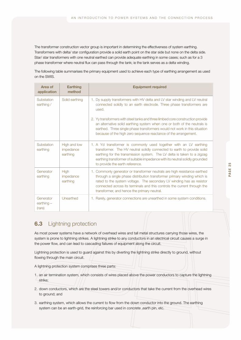
The transformer construction vector group is important in determining the effectiveness of system earthing. Transformers with delta/ star configuration provide a solid earth point on the star side but none on the delta side. Star/startransformerswithoneneutralearthedcanprovideadequateearthinginsomecases;suchasfora3phasetransformerwhereneutralfluxcanpassthroughthetank;iethetankservesasadeltawinding.
The following table summarises the primary equipment used to achieve each type of earthing arrangement as used on the SWIS.
Area of application
Earthing method
Equipment required
Substation earthing /
Solid earthing 1. Dy supply transformers with HV delta and LV star winding and LV neutral connected solidly to an earth electrode. Three phase transformers are used.
2. Yy transformers with steel tanks and three limbed core construction provide an alternative solid earthing system when one or both of the neutrals is earthed. Three single phase transformers would not work in this situation because of the high zero sequence reactance of the arrangement.
Substation earthing
High and low impedance earthing
1. A Yd transformer is commonly used together with an LV earthing transformer. The HV neutral solidly connected to earth to provide solid earthing for the transmission system. The LV delta is taken to a zigzag earthing transformer of suitable impedance with its neutral solidly grounded to provide the earth reference.
Generator earthing
High impedance earthing
1. Commonly generator or transformer neutrals are high resistance earthed through a single phase distribution transformer primary winding which is rated to the system voltage. The secondary LV winding has as resistor connected across its terminals and this controls the current through the transformer, and hence the primary neutral.
Generator earthing – (rare)
Unearthed 1. Rarely, generator connections are unearthed in some system conditions.
6.3 Lightning protection
As most power systems have a network of overhead wires and tall metal structures carrying those wires, the system is prone to lightning strikes. A lightning strike to any conductors in an electrical circuit causes a surge in the power flow, and can lead to cascading failures of equipment along the circuit.
Lightning protection is used to guard against this by diverting the lightning strike directly to ground, without flowing through the main circuit.
A lightning protection system comprises three parts:
1. an air termination system, which consists of wires placed above the power conductors to capture the lightning strike;
2. down conductors, which are the steel towers and/or conductors that take the current from the overhead wires toground;and
3. earthing system, which allows the current to flow from the down conductor into the ground. The earthing system can be an earth-grid, the reinforcing bar used in concrete ,earth pin, etc.
PA
GE
25

G E N E R AT O R G R I D C O N N E C T I O N G U I D E :
6.4 Surge protection
Surge arrestors may be installed on a power system to protect equipment against voltage and current spikes that may flow along a circuit due to a lightning strike (should it not be adequately protected by lightning protection), or switching surges.
Surge protection is commonly installed near transformers to prevent a power surge from causing an insulation fault in the transformer, which can involve lengthy repair times and significant expense. They are also installed on the lines at the entry to substations to prevent damage to instrument transformers.
PA
GE
26

A N I N T R O D U C T I O N T O P O W E R S Y S T E M S A N D T H E C O N N E C T I O N P R O C E S S
7.0 Protection
7.1 What is protection?
Protection equipment takes continuous measurements of various electrical properties of the power system to make sure the system is operating correctly. Protection relays look for indications that there are faults on the system, and then make decisions as to whether it should switch the power off on its allocated protection area. Once a fault has been diagnosed as being within the area the relay is meant to protect, the relay sends a signal to a circuit breaker to switch it off (trip), consequently shutting off the power supply to the fault. The relay should be able to clear a fault to prevent damage to other plant and to maintain system stability.
Protection is designed to detect and trip for a multitude of different fault types. As a result setting the relay requires care, as the relay needs to be set so that it does not trip for normal operating conditions – however trips correctly for all fault types.
7.2 Why is protection required?
Protection serves a number of purposes in a reliable power system:
- the protection of people. A fault releases a large amount of energy at the point of a fault. This energy can easily pass through people standing in the general area of the fault, as well as people near the point of supply. The quicker a fault can be disconnected from the network, the smaller the chance of harm occurring to personnel.
- the protection of assets. The equipment supplying a faulted point on a network will overheat, and likely fail (and consequently become damaged) if the fault is not cleared quickly enough.
- the security of supply. The quick operation of protection to isolate a fault will preserve the supply of power to other parts of the network, reducing disruption to a minimum number of consumers.
- system stability. The quick operation of protection stops the whole power system from becoming unstable. An uncleared fault will may cause the system voltage to collapse and generation to become unstable, leading to incorrect operation and possible damage.
7.2.1 system stability
The system stability largely depends on the ability of a generator to ride through a fault.
If one generator trips off the system, a load imbalance will be created equal to the power output of the tripped generator prior to the trip. Unless other generation can be ramped up to re-balance the system the network will have an unstable frequency.
Generators are required by the network operator to ride through a fault in accordance with the requirements of the technical rules.
The limit at which a fault needs to be cleared before the generator itself needs to be tripped is called the Critical Fault Clearance Time (CFCT).
PA
GE
27

G E N E R AT O R G R I D C O N N E C T I O N G U I D E :
7.2.2 Voltage stability
The system voltage stability depends on the amount of reactive power reserves available to the system during a contingency event. In the event of a fault, the voltage can reduce to 20 to 30 per cent of its typical operating value. At low voltages, capacitor banks lose their ability to supply sufficient amounts of reactive power, and dynamic forms of reactive power supply (such as generation) become critical to restore the system to an acceptable operating voltage.
7.2.3 Security of supply
Security of supply refers to the probability of a fault on the power system causing subsequent loss of supply to consumers. A high security (hence more reliable) supply can be obtained by having backup options for power supply.
In most power systems it is common to build two transmission circuits connecting supply points to load. Installation of two circuits allows for one circuit to be removed from service for any reason, whilst still maintaining supply. This level of security is referred to as N-1 security.
A higher security of supply can be desired for critical services by providing more than one level of redundancy, i.e. N-1-1.
7.3 Generator protection principles
Each type of equipment can have various types of protection installed to protect against the incorrect and potentially damaging operation of that equipment. For example a circuit breaker needs a protection device that knows whether the breaker has switched successfully, whereas the protection for a transformer needs to know if a winding fault has occurred.
The following list outlines abnormal generator operating conditions, which may require some form of protection:
- stator electrical faults
- overload
- overvoltage
- unbalanced loading
- overfluxing
- inadvertent energisation
- rotor electrical faults
- loss of excitation
- loss of synchronism
- failure of prime mover
- lubrication oil failure
- overspeeding
- rotor distortion
- difference in expansion between rotating and stationary parts
- excessive vibration
- core lamination faults
PA
GE
28

A N I N T R O D U C T I O N T O P O W E R S Y S T E M S A N D T H E C O N N E C T I O N P R O C E S S
Protection can be installed to detect these abnormal operating conditions and trip the generator if the condition is sufficiently severe.
The most common types of protection are explained below. For more information see the generator protection section in the Areva Protection Guide.
7.3.1 Overcurrent protection
Overcurrent protection is an essential part of a generator protection scheme. High currents that are above the generator design ratings will cause overheating and subsequent damage to the generator.
7.3.2 Overvoltage protection
Overvoltage protection is important to prevent excessive voltages from breaking down the winding insulation in the generator and causing a fault.
7.3.3 Low forward power/reverse power protection
If the mechanical driving power of the rotor fails in some way, the generator will cease to output power and begin to operate as a motor, possibly causing damage to mechanical machinery connected to the rotor. Protection can detect if the power output of the generator drops to an undesired level, and can also detect if the generator begins to absorb power.
7.3.4 Unbalanced loading
A generator may become unbalanced if a fault occurs on only one or two phases of a three phase system. This can cause the rotor to vibrate and wobble, potentially causing mechanical damage. Protection can be installed to compare all three phases to ensure the power output is balanced.
7.4 Protection equipment
Various types of protection are used depending on the likelihood of faults, the nature of the protected equipment, and the value of the protected equipment and load.
7.4.1 Fuse
A fuse offers a compact solution for the protection of parts of a circuit, however once a fuse is blown, the circuit must be switched off to install a new fuse. Fuses are of significant value when limiting the scale of faults on distribution networks, which are spread over significant geographical area.
7.4.2 Circuit breaker
A circuit breaker is a device that is capable of interrupting a fault current, on receipt of an initiating signal. After the fault is removed, circuit breakers can be closed to restore supply.
7.4.3 Relay
Relays detect the presence of faults and initiate circuit breaker operation.
PA
GE
29

G E N E R AT O R G R I D C O N N E C T I O N G U I D E :
PA
GE
30

A N I N T R O D U C T I O N T O P O W E R S Y S T E M S A N D T H E C O N N E C T I O N P R O C E S S
8.0 Operation
8.1 Synchronising equipment
It is important that a generator is fully running and synchronised with an external power network before it is physically connected, so that no equipment is damaged. To be ready to connect to a power network, the following conditions should be present:
• thevoltagelevelofgenerationshouldmatchthevoltageleveloftheexternalnetwork.
• thefrequencyofgenerationshouldmatchthefrequencyoftheexternalnetwork.
• thepointofcycle(orphaseangle)foreachphaseofgenerationshouldequalthepointofcycleforeachcorresponding phase of the external network.
A synchronising relay checks these conditions by measuring the voltage on both sides of the circuit breaker used for connecting the generator to the grid. Once synchronous conditions are met, the circuit breaker is allowed to close.
Modern synchronising relays and control equipment can fine tune the generator to a point where the generator and external network are closely matched, and then automatically close the electrical circuit to bring the generator online.
Care is required to prevent the incorrect operation of protection from connecting two power systems that are out of synchronism. Protection schemes generally take care of this by ensuring that connection of two power systems occurs at circuit breakers that are monitored by synchronising relays.
8.2 Modes of generator operation
There are various modes of controlling real and reactive power output from a generator, and each mode affects the quality of the surrounding power system in different ways.
Some generators will take responsibility for the frequency control on the network. For any power system, there must be at least one generator controlling the frequency. These generators balance any instantaneous changes in active and reactive power demand on the network.
Other generators may take a joint responsibility for the voltage control for parts of the network. There is no minimumnumberofgeneratorsthatarerequiredtorunonvoltagecontrolmode;howeveraparticulargeneratormay be required to run in voltage control mode to keep the voltage stable on weak areas of the network.
A generator can also output power without providing frequency regulation and voltage control of the system. This mode allows the generator to put out a constant level of power, regardless of the load.
8.2.1 Frequency control
The frequency of the power system needs to be kept relatively constant, so equipment connected to the power system will act reliably. The frequency of the power system affects the rotation speed of synchronous machines, and also some electric clocks use the power frequency to measure time.
There are two methods for controlling the frequency of the power system:
• isochronous mode – When operating in isochronous mode the generator will vary its power output as power demand changes to fix the frequency to 50Hz. Additional generators on the same power system will continue to produce a scheduled amount of power unless manual intervention is necessary (i.e. during extreme loading scenarios).
PA
GE
31

G E N E R AT O R G R I D C O N N E C T I O N G U I D E :
• droop mode – Multiple generators can share the responsibility of generator/load balance by operating in droop mode. The generator control in droop mode looks at the power system frequency, and adjusts the output of the generator from its nominal setpoint depending on the extent of the system frequency variation fromthetargetvalue.Forinstance;at50.1Hzthegeneratormayputout10MW(orminimumsetpoint)andat 40.9 Hz the generator puts out 100MW. Normally a four per cent change in frequency results in a 100 per cent change in output. This mode allows for load sharing between generators of different size during system frequency changes. However the frequency is not fixed like in isochronous mode.
Isochronous mode can also provide a droop response in the short term and then over a longer time frame return the frequency to 50 Hz.
8.2.2 Voltage control
Synchronous generators (and reactive compensation plant associated with induction generators) are able to deliberately affect the voltage at their connection point. Operation of these types of generation with automatic voltage control is preferred as it gives the best system performance. The voltage control setpoints may need to be carefully coordinated with other system components. This mode can be helpful to allow a generator have greater flexibility with scheduling power output with respect to varying system conditions. This is especially true when considering a generator exporting power from a weak area of the network.
8.2.3 Power factor control
An alternative is for a generator to give an amount of voltage support that increases in proportion to the generator output. This mode is often used when a relatively weak generator is connected to a relatively strong network. It is a simple way to avoid the generator controls. The disadvantage is that the support provided by the generator is not adjusted to suit varying network conditions.
A method of sharing the contribution to voltage control based on machine size is to have the machine control the voltage at the generator terminals rather than at the point of connection. This effectively provides a level of voltage droop control.
8.2.4 Islanded operation
An ‘island’ on the power system refers to an electrical separation in the network that causes the power system to break up into 2 or more power systems, which can then operate independently of each other if there is a sufficient balance between generation and load. An island can often occur when a single circuit supplying a network area faults, and is disconnected by protection.
Generation can be designed to continue operation if the section of network to which it is connected becomes islanded. In this role the generator needs to take responsibility for the frequency control and voltage control on the islanded power system.
A power system split requires careful generator control to avoid an outage of the power supply on either side of the split. The more power flowing through the circuit where the network is split, the harder it will be to maintain a continuous power supply without outage.
Additionally, care needs to be taken when re-connecting an island to the main grid without a power outage. Synchronising relays are required to check that both systems are in synchronism with each other.
PA
GE
32
A N I N T R O D U C T I O N T O P O W E R S Y S T E M S A N D T H E C O N N E C T I O N P R O C E S S
9.0 Generation/load balance
9.1 Swinging generators
Swinging generators take the role of the real-time balance of power supply and demand, as well as maintaining a constant power system frequency of 50 Hertz. These generators are controlled by electronic control systems in Frequency control mode (see Section 9.2.1), which are monitored by the Independent Market Operator (IMO).
The total capacity of swinging generation needs to have enough range to handle short-term demand changes on the power system. Additional generation can be scheduled over the medium and long term to meet the daily trend of power consumption.
If the swinging generators are producing close to their power output limits, the IMO may request that the power output of some reserve generation is ramped up. This will allow the swinging generators to operate more comfort-ably within their range of power output.
9.2 Dispatch of generators
The South West Interconnected System (SWIS) has an Independent Market Operator or IMO, that take the role of matching supply and demand for power as well as administrating a Short Term Energy Market (STEM). The IMO also has created a set of market rules, which outline the needs of all persons who use the power system in some form.
Generators must subscribe to the market rules as a ‘Market Generator’ if the size of generation is 10MW or larger.
Generation smaller than 10MW have the option of subscription, and this may be an option if power is generated on a large consumers network, where power is never anticipated to be exported onto the larger grid.
A large, consistent source of generation will require a generator to register to the market rules as a scheduled generator. This allows the IMO to allocate enough generation to meet demand through the following day of opera-tion.
A generation source that cannot be forecast to provide a consistent level of power needs to be registered as a non-scheduled generator. Wind and solar generation operate in this category.
9.3 Reserve generation
The Independent Market Operator has to make sure that there is sufficient extra capacity available to generate for any increase in load above forecast values, as well as providing a safety margin should any generator on the system trip, and leave a large load imbalance.
The IMO allocates a larger generation capacity than anticipated demand to leave a margin for either unforeseen loss of the largest generator, or unforeseen load increase. During either of these scenarios, a generator may be asked to ramp up power output to balance generation to the current level of demand.
Non-scheduled generation will not usually form part of the generation reserves.
PA
GE
33

G E N E R AT O R G R I D C O N N E C T I O N G U I D E :
PA
GE
34

A N I N T R O D U C T I O N T O P O W E R S Y S T E M S A N D T H E C O N N E C T I O N P R O C E S S
10.0 Glossary
Real power The supply of energy per second
Reactive power The type of power that flows in capacitors and inductors and is used to control voltage in the network.
Faults Breakdown of insulation causing current to flow between phases or from phases to earth
Circuit breakers A device capable of disconnecting a circuit during a fault
Short circuit See Faults
Transformers Devices used to transform the voltages on an alternating current network
Surge arrestors A device for limiting the overvoltages on the network
Synchronising relays A relay that provides signals to a generator so that the generators speed, phase angle and voltage match the network prior to closing the generator circuit breaker.
Protection Devices used to detect network faults and initiate isolation of the faulted equipment.
SCADA Supervisory Control and Data Acquisition
Earthing See section 7.0
Sub-transient reactance The impedance of a generator presented to the network immediately following the application of a fault.
Stepup/step down transformer
A transformer used to raise/lower voltage ad measured from source to load side.
Waterhead The hight of the water column supply a hydraulic turbine
Tapchangers A device used to change the ratio of a transformer and hence assist with the control of voltage.
Power quality Measure of the degree to which the shape of the voltage wave matches the ideal.
Sinusoidal Shaped as a Sine wave
PA
GE
35

G E N E R AT O R G R I D C O N N E C T I O N G U I D E :
PA
GE
36

A N I N T R O D U C T I O N T O P O W E R S Y S T E M S A N D T H E C O N N E C T I O N P R O C E S S
11.0 AppendixGrid connection is a formal process. It involves participation in a queue of applications (to enable first-come, first served access to unused capacity in the network) and culminates in a legally binding Connection Offer. Particularly for large generators (or generators that are large relative to the network strength at the proposed connection point) it requires significant technical and economic studies to be carried out, using information specific to the design of the individual generator to be connected.
Generator proponents may be unable or unwilling to commit to the full connection process. For instance:
• theprojectmaybeatapreliminarystageofassessmentandrequireonlyanindicationoffeasibility,ratherthanreservation of a place in the queue followed by a connection offer.
• theprojectmaybeatapreliminaryfundingstageandnotyetreadytocommitthefundsrequiredforpreparation of an access offer.
• theengineeringdesignoftheproject(includingselectionofaparticularmanufacturerandmodelofgenerator)may not yet be finalised and so engineering data cannot yet be provided.
In these circumstances, a preliminary study (without queue reservation and processing of an access offer) may be more appropriate.
11.1 Explanation of application process
Connection to Western Power Network
The application process to connect to the Western Power Network is given on the following page.
WesternPowerrequirestechnicalinformationaboutthegeneratingunittobeinstalled;fuelsourcetobeused,and various design characteristics that determine the response of the generator to system changes. Western Power then run system impact studies, which assess the performance of the generator with respect to the operating ranges outlined in the technical rules, which are explained in section 1.3. More information on the studies performed by Western Power is given in Section 1.2.
Western Power has a spreadsheet of required technical data on their website, with different versions available for transmission or distribution connections. This spreadsheet can be found at:
http://www.westernpower.com.au/mainContent/connectionsUpgrades/newConnections/Generators.html P
AG
E 3
7
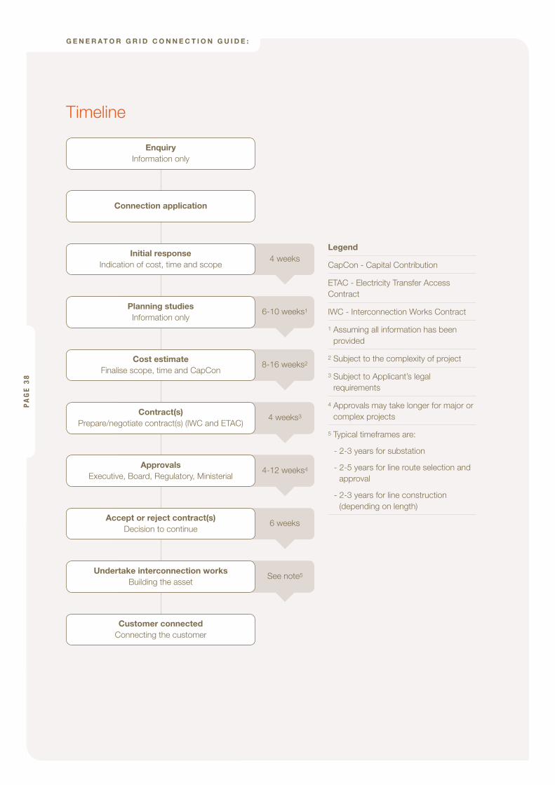
G E N E R AT O R G R I D C O N N E C T I O N G U I D E :
PA
GE
38
Enquiry Information only
Connection application
Initial response Indication of cost, time and scope
4 weeks
Planning studies Information only
6-10 weeks1
Cost estimate Finalise scope, time and CapCon
8-16 weeks2
Contract(s) Prepare/negotiate contract(s) (IWC and ETAC)
4 weeks3
Approvals Executive, Board, Regulatory, Ministerial
4-12 weeks4
Accept or reject contract(s) Decision to continue
6 weeks
Undertake interconnection works Building the asset
See note5
Customer connected Connecting the customer
Legend
CapCon - Capital Contribution
ETAC - Electricity Transfer Access Contract
IWC - Interconnection Works Contract
1 Assuming all information has been provided
2 Subject to the complexity of project
3 Subject to Applicant’s legal requirements
4 Approvals may take longer for major or complex projects
5 Typical timeframes are:
- 2-3 years for substation
- 2-5 years for line route selection and approval
- 2-3 years for line construction (depending on length)
Timeline

A N I N T R O D U C T I O N T O P O W E R S Y S T E M S A N D T H E C O N N E C T I O N P R O C E S S
PA
GE
39
D R A F TRegistration as a Market Generator with the Independent Market Operator (IMO)
Companies that plan on adding new generation are required to register as a market participant with the IMO. The registration process will setup the financial framework used to engage in trading and complete financial transactions.
Further details of the registration process with the IMO are given here:
http://www.imowa.com.au/Attachments/Prudential/General%20registration%20instructions_rev4.pdf
Registration of generation facilities with the IMO
Once the company has registered as a market participant, the company is then required to apply for registration of each new generation facility with the IMO. The application is an online process, and requires information about contractual agreements for operation as well as relevant technical information about the generator facility.
Further details of the registration process with the IMO are given here:
http://www.imowa.com.au/Attachments/Prudential/General%20registration%20instructions_rev4.pdf
Generating License with ERA
Application for a generating license is required if the amount of generation at the connection point is greater than 30 MW. A guide to the application process is given on the ERA website, or using the link below:
http://www.era.wa.gov.au/cproot/4976/20586/Licence%20Application%20Guidelines%20and%20Forms.pdf
11.2 Generator modelling requirements
The operation of a generator needs to be modelled and simulated as part of the power system before commissioning to check the generator can follow the guidelines for operation outlined in the technical rules.
The modelling process includes several types of simulation, with each simulation testing the performance of the generator a different group of requirements as outlined in the technical rules.
During the analysis process, particular attention is paid to the operation of the generation during a time where the power system is under stress (most likely due to a contingency event).
The analysis results provide the basis for managing the generation output and local network over a full range of contingency events in a stable and reliable manner. The results will also indicate whether extra electrical equipment is required to achieve the desired power output over a full range of contingency events, while complying with the requirements of the technical rules.

G E N E R AT O R G R I D C O N N E C T I O N G U I D E :
PA
GE
40
DR
AF
T
The
gene
rato
r is
requ
ired
to c
ontr
ibut
e to
war
ds th
e co
st o
f any
upg
rade
s re
quire
d to
com
ply
with
the
tech
nica
l rul
es. M
ore
info
rmat
ion
is g
iven
in S
ectio
n 1.
6 C
osts
to c
on-
nect
. The
Cap
ital C
ontr
ibut
ions
Pol
icy
is a
vaila
ble
at:
http
://w
ww
.wes
tern
pow
er.c
om.a
u/do
cum
ents
/Acc
essA
rran
gem
ent/
2007
/Acc
ess%
20A
rran
gem
ent/
AM
EN
DE
D_P
RO
PO
SE
D_A
CC
ES
S_A
RR
AN
GE
ME
NT_
-_A
PP
EN
DIX
_3_-
_C
AP
ITA
L_C
11.2
.1 M
ain
Sim
ulat
ion
Type
s
Tab
le 1
: out
lines
the
mai
n ty
pes
of s
imul
atio
n re
qui
red
bef
ore
conn
ectin
g to
a p
ower
sys
tem
.
Sim
ulat
ion
Typ
eD
escr
ipti
on/
Pur
po
seP
ote
ntia
l Iss
ues
Det
ecte
dD
ata
Req
uire
d
Load
flow
Load
flow
ana
lysi
s ch
ecks
that
a g
ener
a-to
r ca
n pr
oduc
e an
y le
vel o
f pow
er d
urin
g an
y fe
asib
le lo
adin
g co
nditi
on p
lace
d on
the
pow
er s
yste
m, w
ithou
t bei
ng c
onst
rain
ed b
y th
e op
erat
ing
limits
of t
he p
ower
sys
tem
.
Con
tinge
ncy
even
ts s
uch
as th
e pl
anne
d or
un
plan
ned
outa
ge o
f maj
or e
lect
rical
equ
ip-
men
t are
stu
died
com
preh
ensi
vely
to c
heck
w
hat g
ener
atio
n op
erat
ing
cons
trai
nts
will
appl
y du
ring
the
cont
inge
ncy.
Ove
r/un
der
volta
ges
•
Ove
rload
ing
•
Ade
quat
e ac
tive
and
reac
tive
•po
wer
rese
rves
Ope
ratio
nal c
onst
rain
ts/p
reca
u-•
tions
requ
ired.
Sin
gle
Line
Dia
gram
sho
win
g m
ajor
tran
sfor
mer
s, b
us
•na
mes
, vol
tage
leve
ls, l
ines
/cab
les/
othe
r el
ectr
ical
equ
ip-
men
t and
poi
nt o
f con
nect
ion
to tr
ansm
issi
on s
yste
m, a
s w
ell a
s lo
cal n
etw
ork.
Res
ista
nce
and
reac
tanc
e da
ta fo
r al
l maj
or e
quip
men
t in
•th
e m
odel
led
netw
ork.
Thi
s in
clud
es li
ne le
ngth
s.
Siz
e of
gen
erat
or(s
), an
d op
erat
ing
limits
.•
Rat
ed c
urre
nt, v
olta
ge r
ange
of e
xist
ing
and
prop
osed
•
elec
tric
al e
quip
men
t.
Load
siz
e in
act
ive
and
reac
tive
pow
er.
•
Info
rmat
ion
on v
olta
ge a
nd ta
ppin
g co
ntro
l.•
Sho
rt c
ircui
tS
hort
Circ
uit a
naly
sis
serv
es th
e fo
llow
ing
purp
oses
:
Allo
win
g th
e cu
rren
t trig
ger
leve
l of p
rote
c-•
tion
rela
ys to
be
accu
rate
ly s
et.
Ens
urin
g el
ectr
ical
equ
ipm
ent i
s ad
equa
te-
•ly
rat
ed to
han
dle
faul
t cur
rent
.
Pro
vidi
ng in
form
atio
n re
quire
d to
des
ign
•th
e ea
rthi
ng s
yste
m.
Faul
t rat
ing
of c
onne
cted
equ
ip-
•m
ent e
xcee
ded.
Com
plet
e se
t of l
oad
flow
dat
a•
Zero
seq
uenc
e im
peda
nce
for
all e
quip
men
t (ne
cess
ary
for
•ea
rth
faul
ts)
Gen
erat
ion
and
load
sub
-tra
nsie
nt re
acta
nce
valu
es.
•
Ear
thin
g de
tails
for
tran
sfor
mer
s, g
ener
ator
s an
d ot
her
•m
isce
llane
ous
elec
tric
al e
quip
men
t.

A N I N T R O D U C T I O N T O P O W E R S Y S T E M S A N D T H E C O N N E C T I O N P R O C E S S
Sim
ulat
ion
Typ
eD
escr
ipti
on/
Pur
po
seP
ote
ntia
l Iss
ues
Det
ecte
dD
ata
Req
uire
d
Sta
bilit
y st
udie
sS
tabi
lity
stud
ies
look
at h
ow a
pow
er s
yste
m
oper
ates
dur
ing
dist
urba
nces
. A c
omm
on
obje
ctiv
e is
to s
ee h
ow lo
ng a
pro
tect
ion
devi
ce c
an ta
ke to
cle
ar a
faul
t bef
ore
the
gene
rato
r (a
nd p
ossi
bly
the
surr
ound
ing
pow
er s
yste
m) b
ecom
es u
nsta
ble.
Sta
bilit
y st
udie
s al
so a
id in
fine
-tun
ing
the
gene
ratio
n co
ntro
l sys
tem
s th
at m
anag
e po
wer
tran
sfer
.
Insu
ffici
ent t
ime
to c
lear
a fa
ult.
•
Freq
uent
inte
rrup
tions
to p
ower
•
tran
sfer
cau
sed
by u
npla
nned
ge
nera
tor/
equ
ipm
ent o
utag
e.
Unw
ante
d or
poo
rly d
ampe
d •
Pow
er tr
ansf
er fl
uctu
atio
ns a
nd
osci
llatio
ns a
risin
g fro
m c
ontr
ol
syst
em c
onfli
cts.
Exc
essi
ve fr
eque
ncy
varia
tions
.•
Insu
ffici
ent v
olta
ge re
cove
ry a
fter
•tr
ansi
ent e
vent
s.
Com
plet
e se
t of d
ata
incl
udin
g:
Load
Flo
w a
nd F
ault
Leve
l Dat
a•
Gen
erat
ion
and
load
sub
-tra
nsie
nt re
acta
nce
valu
es a
nd
•tim
e co
nsta
nts
and
othe
r m
odel
ling
para
met
ers.
Mec
hani
cal c
onst
ants
and
phy
sica
l pro
pert
ies
for
the
•ge
nera
tor
and
load
s
Blo
ck d
iagr
am o
utlin
ing
the
logi
c us
ed to
con
trol
the
gen-
•er
ator
s re
al a
nd re
activ
e po
wer
out
put
A m
odel
of t
he g
ener
ator
and
con
trol
sch
eme
suita
ble
for
•op
erat
ing
on W
este
rn P
ower
’s a
naly
sis
prog
ram
.
Tab
le 1
: Typ
es o
f sim
ulat
ion
per
form
ed t
o ch
eck
the
inte
ract
ion
of a
gen
erat
or w
ith a
pow
er s
yste
m.
PA
GE
41

G E N E R AT O R G R I D C O N N E C T I O N G U I D E :
11.2.2 The importance of accurate data
In order to obtain realistic results from simulation studies, accurate data must be used. In general, this will require the details of the proposed design to be finalised before studies can begin. The generator type (manufacturer and model), and in many cases details of particular control systems (manufacturer and model for excitation and governor systems) are key inputs to the studies and accurate data is required. Studies use data specific to the individual type of machine being proposed for installation. This includes measured “type test” data, and physical models based on the details of the particular installation and its controls. This test data must be based on or measured from the performance of real machines so that a definitive answer can be obtained from the studies. Study results can differ significantly even for machines of the same general type, as they depend on the details of the individual equipment.
Each issue identified in section 1.2.1 can pose a problem to the power system if inadequate or inaccurate data is provided for studies.
The results of the generator modelling studies are used to fine tune protection and control systems so that the system will perform correctly during normal operating conditions, and will recover quickly from faults.
Inaccurate generator data can lead to the control systems being inappropriately tuned, which can cause the system to oscillate under normal operating conditions, as well as taking longer to recover after faults have occurred.
Data which have a critical role in the stability of the generator are as follows:
• inertiaoftheprimemoverandgenerator
• timeconstantsofthefueldeliverysystem
• governor/Excitertimeconstants
• overallresponsetimeofthegeneratortochangesonthepowersystem
11.2.3 Additional simulation types
The following simulation types can be used to simulate other disruptions to the power system:
• Harmonics–Itisnecessarytoperformharmonicsstudiesforconnectedgenerationifsignificantamountsofthe installed equipment use Variable Speed Drives, Inverters or any other power electronic equipment. These types of equipment switch many times per second, and can degrade the quality of power delivered to other equipment.
• Motorstarting–Iflargemotorsarepresentonthegenerationsystem,thenmotorstartingstudiesarerequiredto ensure that the voltage during start does not drop low enough to cause disruption to other equipment. Motor studies may also be required to ensure that power plant auxiliaries (especially boiler feed pumps) can recover successfully from a system voltage disturbance.
The necessity of these studies will depend on the characteristics of the generator as well as the type of auxiliary electrical plant installed.
11.2.4 Application of studies with respect to the technical rules
Each type of study will check for problems using the Technical rules as a basis for investigation. Table 2 shows the sections of the technical rules that are applicable to each type of study.
PA
GE
42

A N I N T R O D U C T I O N T O P O W E R S Y S T E M S A N D T H E C O N N E C T I O N P R O C E S S
Simulation type Relevant sections of the technical rules
Load Flow 2.2.2 – Steady State Power Frequency Voltage2.2.5 – Negative Phase Sequence Voltage (Unbalanced Load Flow)
Short Circuit 2.5.7 – Maximum Fault Currents
Stability Studies 2.2.1 – Frequency Variations2.2.7 – Transient Rotor Angle Stability2.2.8 – Oscillatory Rotor Angle Stability2.2.9 – Short Term Voltage Stability2.2.10 – Temporary Over-Voltages2.2.11 – Long Term Voltage Stability2.3.7 – Power System Stability and Dynamic Performance2.9.4 – Maximum Total Fault Clearance Times
Power Quality 2.2.3 – Flicker2.2.4 – Harmonics
Motor Starting 2.2.2 (b)– Step Changes in steady state voltage levels2.2.3 – Flicker
Table 2: Relevant Sections of the technical rules for different study types.
The additional sections of Chapter 2 outline the obligations of Western Power to meet operating criteria, as well as specifying how the models are to be set up in order to perform studies.
Section 3 outlines the obligations of a user (the generator) to meet operating criteria at the point of connection to the network operated by Western Power.
11.3 Governance of power systems in West Australia
The Office of Energy administers the legal framework for the operation of the power system, on behalf of the State Government.
Economic regulation of the power system is administered by the Economic Regulation Authority (ERA), who is also responsible for Gas, Rail and Water networks. The economic regulation allows for the Independent Market Operator (IMO) to manage the wholesale energy market, according to the Market rules written and agreed to by the ERA.
technical rules have been written by Western Power to ensure the satisfactory operation of the power system and have been agreed to by the ERA. These rules ensure the operation of the power system reflects the interests of all stakeholders.
11.4 Explanation of relevant legislation and codes
The Office of Energy governs the power system in Western Australia.
Electricity Industry Act 2004 (Office of Energy) – This legislation gives responsibilities for the economic administration of the power system to the ERA. Provision is also made for the formation of the Electricity Networks Access Code.
http://www.slp.wa.gov.au/statutes/swans.nsf/DisplayPDF?Openagent&Type=S&ID=61E650A8AECA07FE482571A800056796
PA
GE
43

G E N E R AT O R G R I D C O N N E C T I O N G U I D E :
Electricity Networks Access Code 2004 – This code outlines commercial arrangements, including charges that apply to electricity generators and retailers accessing Western Power’s electricity network within the South West Interconnected System (SWIS). Initially, only the SWIS is covered under the Access Code, but there is potential for other networks to be covered.
http://www.slp.wa.gov.au/gazette/gazette.nsf/gazlist/2C360789573C223148256F5C0010ED84/$file/gg205.pdf
Technical rules (Western Power) – The technical rules promote the economically efficient, safe and reliable production and supply of electricity and electricity related services in the South West interconnected system. These rules are written by Western Power and approved by the Economic Regulation Authority.
http://www.westernpower.com.au/mainContent/workingWithPower/NetworkAccessServices/accessArrangement/accessArrangement.html#Technical
Wholesale Electricity Market Design Summary – This document outlines the structure of the wholesale electricity market, and gives a general overview of the market rules.
http://www.imowa.com.au/Attachments/MarketSummarySeptember2006.pdf
Market rules (IMO and ERA) – The market rules provide legislation about how the wholesale electricity market is to be run.
http://www.imowa.com.au/market_rules.htm
The Wholesale Market Objectives are defined in the Wholesale Market Rules. They are:
1. to promote the economically efficient, safe and reliable production and supply of electricity and electricity relatedservicesintheSouthWestinterconnectedsystem;
2. to encourage competition among generators and retailers in the South West interconnected system, including byfacilitatingefficiententryofnewcompetitors;
3. to avoid discrimination in that market against particular energy options and technologies, including sustainable energy options and technologies such as those that make use of renewable resources or that reduce overall greenhousegasemissions;
4. to minimise the long-term cost of electricity supplied to customers from the South West interconnected system;and
5. to encourage the taking of measures to manage the amount of electricity used and when it is used.
Network Quality and Reliability of Supply Code (Office of Energy) – This document sets out determine the limits of acceptable variation of power quality on the power system, and the penalties for exceeding these limits. These standards include the maximum amount in minutes per year that a customer is without power.
http://www.energy.wa.gov.au/2/3193/64/network_quality.pm
Metering Code 2005 (Office of Energy) – Details the generators metering requirements for the power they generate.
http://www.slp.wa.gov.au/gazette/GAZETTE.NSF/gazlist/1B502E19E514347D482570DF0010E50E/$file/gg243.pdf
PA
GE
44

A N I N T R O D U C T I O N T O P O W E R S Y S T E M S A N D T H E C O N N E C T I O N P R O C E S S
11.5 Differences between East and West Australia
Requirements to enter into the market as a prospective generator differ from the East Coast of Australia, due to differences in the regulatory framework between Australian states.
A prospective generator in Western Australia needs to invest in network upgrades, should they be required. This allows the generator to operate at full capacity without exceeding normal limits. Unlike other jurisdictions, the generator then has the right to transfer their full capacity into the network in the future, without making further capital investment. This protects a generator already connected to the system from being constrained in the future or having to contribute towards grid investment necessary for the new generation of a third party. The Access Charges cover the cost of maintaining this capability.
11.6 Costs to connect
The following list identifies the typical costs that a prospective generator can expect when connecting generation of 30MW or more to the South West Interconnected System.
• ERAlicenseprocessingfee–ThisfeeispayabletolicensethegenerationfacilitywiththeERA.
• IMOregistrationfees–OnefeeispayabletoregisterasamarketgeneratorwiththeIMO.Thisfeecoversthe administration cost of the admission of the generation company to the Wholesale Electricity Market. An additional fee is payable for each new generation facility registered with the IMO.
• anERAlicenseisnotrequiredforgeneratorsbelow30MW,andregistrationwithIMOisnotrequiredforgenerators under 10MW.
• WesternPowerProcessingCosts–WesternPowerchargesacosttoensureanewgenerationfacilitymeetsthe technical rules for connection to the South West Interconnected System. This involves modelling the network with the new generator connected to check system performance. Western Power will estimate a processing cost based on information contained in the application for access before any modelling is carried out.
• CapitalContributiontowardsgridupgrades(ifrequired)–Ifthesystemperformancelimitsarenotmetoverthefull range of generation, Western Power will suggest a grid upgrade solution. The generator will incur costs for the grid upgrade. Western Power will then assure that the Generator will be able to produce power over its entire range without any future capital investment in the grid.
Capital contribution costs can be broken up into two categories:
1. shallow network reinforcements – Grid upgrades required at or near the point of connection are referred to as shallow network reinforcements. The shallow network reinforcements are the costs associated with the extra connection assets required to connect the generator to the grid.
2. deep network reinforcements – The addition of a new generator to the system may also cause operational limits to be exceeded at distant points on the transmission network. In this case the system will require deep network reinforcements to ensure the network can transfer the generator power output to the load. The deep reinforcements could be new transformers, static var compensators (SVCs) capacitor banks and lines that are remote from the new generator.
• WesternPowerConnectionCosts–Thesearechargesto‘usethesystem’onanongoingbasis.
PA
GE
45

G E N E R AT O R G R I D C O N N E C T I O N G U I D E :
11.7 Self evaluations – connection checklist
The following checklist should be completed before approaching Western Power for access to the South West Interconnected System (SWIS).
1. the requirements for connection of generation outlined in sections 3.2 and 3.3 of the technical rules should be read, understood and incorporated into the generation design.
The application to Western Power for connection should include the following information (most of the technical data can be completed in the application spreadsheet):
1. generator technical data should be provided to Western Power (most of this data is obtainable from the generator manufacturer)
2. provision of a single line diagram(s) showing generators, the generator switchboard, loads powered by local supply, transformer information etc.
3. details of the protection design (type of protection used, as well as protection configuration), outlining compliance with generator’s tolerance to acceptable variations in power quality.
4. the requested services start date and requested services end date, for works.
5. the capacity requested for power transfer into the grid.
6. a full description of any exemptions to the technical rules sought by the applicant under Chapter 12 of the Code together with an explanation of why compliance cannot be achieved.
PA
GE
46

A N I N T R O D U C T I O N T O P O W E R S Y S T E M S A N D T H E C O N N E C T I O N P R O C E S S

G E N E R AT O R G R I D C O N N E C T I O N G U I D E :
Customer Services Division 363 Wellington Street Perth WA 6000