generator protection m-3425a - jsk
TRANSCRIPT
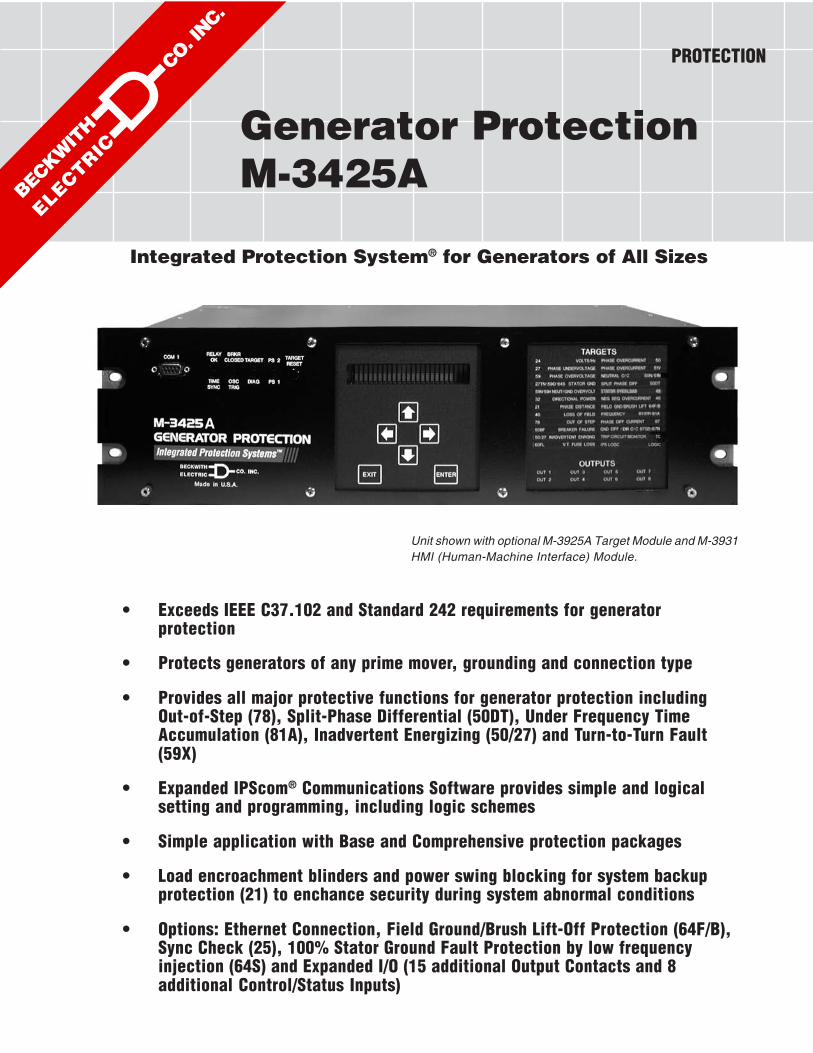
Generator ProtectionM-3425A
Integrated Protection System® for Generators of All Sizes
• Exceeds IEEE C37.102 and Standard 242 requirements for generatorprotection
• Protects generators of any prime mover, grounding and connection type
• Provides all major protective functions for generator protection includingOut-of-Step (78), Split-Phase Differential (50DT), Under Frequency TimeAccumulation (81A), Inadvertent Energizing (50/27) and Turn-to-Turn Fault(59X)
• Expanded IPScom® Communications Software provides simple and logicalsetting and programming, including logic schemes
• Simple application with Base and Comprehensive protection packages
• Load encroachment blinders and power swing blocking for system backupprotection (21) to enchance security during system abnormal conditions
• Options: Ethernet Connection, Field Ground/Brush Lift-Off Protection (64F/B),Sync Check (25), 100% Stator Ground Fault Protection by low frequencyinjection (64S) and Expanded I/O (15 additional Output Contacts and 8additional Control/Status Inputs)
Unit shown with optional M-3925A Target Module and M-3931HMI (Human-Machine Interface) Module.
PROTECTION

–2–
M-3425A Generator Protection Relay
Optional Protective Functions• Sync Check with Phase Angle, ΔV and ΔF
with dead line/dead bus options (25)• Field Ground (64F) and Brush Lift Off (64B)
(Includes M-3921 Field Ground Coupler)• 100% Stator Ground protection by low fre-
quency injection (64S). The following equip-ment is supplied with the 64S option:– 20 Hz signal generator (430-00426)– Band-pass Filter (430-00429)
Standard Features• Eight programmable outputs and six pro-
grammable inputs• Oscillographic recording with COMTRADE
or BECO format• Time-stamped target storage for 32 events• Metering of all measured parameters and
calculated values• Three communications ports (two RS-232
and one RS-485)• M-3820D IPScom® Communications Soft-
ware• Includes MODBUS and BECO 2200
protocols• Standard 19" rack-mount design (vertical
mounting available)• Removable printed circuit board and power
supply• 50 and 60 Hz models available• Both 1A and 5 A rated CT inputs available• Additional trip inputs for externally connected
devices• IRIG-B time synchronization• Operating Temperature: –20° C to +70° C• Sequence of Events Log• Trip Circuit Monitoring• Breaker Monitoring• Four Setpoint Groups
Optional Features• Redundant power supply• M-3925A Target Module• M-3931 Human-Machine Interface (HMI)
Module• RJ45 Ethernet port utilizing MODBUS over
TCP/IP and BECO2200 over TCP/IP proto-cols
• M-3801D IPSplot® PLUS Oscillograph Analy-sis Software
• Expanded I/O (15 additional outputs and 8additional inputs)
Protective FunctionsBase Package
• Overexcitation (V/Hz) (24)• Phase Undervoltage (27)• Directional power sensitive triple-setpoint Re-
verse Power, Low Forward Power or Over-power detection, one of which can be used forsequential tripping (32)
• Dual-zone, offset-mho Loss of Field (40), whichmay be applied with undervoltage controlledaccelerated tripping
• Sensitive Negative Sequence Overcurrent pro-tection and alarm (46)
• Instantaneous Phase Overcurrent (50)• Inadvertent Energizing (50/27)• Generator Breaker Failure (50BF)• Instantaneous Neutral Overcurrent (50N)• Inverse Time Neutral Overcurrent (51N)• Three-phase Inverse Time Overcurrent
(51V) with voltage control and voltage re-straint.
• Phase Overvoltage (59)• Neutral Overvoltage (59N)• Multi-purpose Overvoltage (59X)• VT Fuse-Loss Detection and blocking
(60FL)• Residual Directional Overcurrent (67N)• Four-step Over/Underfrequency (81)• Phase Differential Current (87)• Ground (zero sequence) Differential Current
(87GD)• IPSlogicTM takes the contact input status and
function status and generates outputs byemploying (OR, AND, and NOT) booleanlogic and a timer.
Protective FunctionsComprehensive PackageThe Comprehensive Package includes all BasePackage functions, as well as the following:
• Three-zone Phase Distance protection forphase fault backup protection (21). Zone threecan be used for Out-of-Step Blocking. Loadencroachment blinders can be applied.
• 100% Stator Ground Fault protection using ThirdHarmonic Neutral Undervoltage (27TN) or (59D)Third Harmonic Voltage Differential (ratio)
• Stator Overload (49) (Positive SequenceOvercurrent)
• Definite Time Overcurrent (50DT) can be usedfor split phase differential
• Out-of-Step (78)• UnderFrequency Accumulation (81A)• Rate of Change of Frequency (81R)

–3–
M-3425A Generator Protection Relay
PROTECTIVE FUNCTIONSDevice SetpointNumber Function Ranges Increment Accuracy†
Phase Distance (three-zone mho characteristic)
Circle Diameter #1,#2,#3 0.1 to 100.0 Ω 0.1 Ω 0.1 Ω or 5%(0.5 to 500.0 Ω) ( 0.5 Ω or 5%)
Offset #1,#2,#3 –100.0 to 100.0 Ω 0.1 Ω 0.1 Ω or 5%(–500.0 to 500.0 Ω) ( 0.5 Ω or 5%)
Impedance Angle #1,#2,#3 0° to 90° 1° 1°
Load Encroachment Blinder #1,#2,#3Angle 1° to 90° 1° 1°R Reach 0.1 to 100 Ω
Time Delay #1,#2,#3 1 to 8160 Cycles 1 Cycle 1 Cycle or 1%
Out-of-Step Delay 1 to 8160 Cycles 1 Cycle 1 Cycle or 1%
Overcurrent Supervision 0.1 to 20 A 0.1 A 0.1 A or 2%(0.02 to 4 A) 0.01 A 0.02 A or 2%
When out-of-step blocking on Zone 1 or Zone 2 is enabled, Zone 3 will not trip and it will be used to detect theout-of-step condition for blocking Function 21 #1 and/or 21 #2.
Volts / Hz
Definite TimePickup #1, #2 100 to 200% 1% 1%
Time Delay #1, #2 30 to 8160 Cycles 1 Cycle 25 Cycles
Inverse Time
Pickup 100 to 200% 1% 1%Characteristic Curves Inverse Time #1–#4 — —
Time Dial: Curve #1 1 to 100 1Time Dial: Curves #2–#4 0.0 to 9.0 0.1
Reset Rate 1 to 999 Sec. 1 Sec. .02 Sec. or 1%(from threshold of trip)
The percent pickup is based on nominal VT secondary voltage and nominal system frequency settings. Thepickup accuracy stated is only applicable from 10 to 80 Hz, 0 to 180 V, 100 to 150% V/Hz and a nominal voltagesetting of 120 V.
Phase Undervoltage
Pickup #1, #2, #3 5 to 180 V 1 V 0.5 V or 0.5%0.8 V or 0.75%*
Time Delay #1, #2, #3 1 to 8160 Cycles 1 Cycle 1 Cycle or 0.5%**
* When both RMS and Line-Ground to Line-Line VT connection is selected.
**When RMS (total waveform) is selected, timing accuracy is O20 cycles or 1%.
†Select the greater of these accuracy values. Values in parentheses apply to 1 A CT secondary rating.
21
24
27

–4–
M-3425A Generator Protection Relay
PROTECTIVE FUNCTIONS (cont.)Device SetpointNumber Function Ranges Increment Accuracy†
Third-Harmonic Undervoltage, Neutral
Pickup #1, #2 0.10 to 14.00 V 0.01 V 0.1 V or 1%
Positive SequenceVoltage Block 5 to 180 V 1 V 0.5 V or 0.5%
Forward Under Power Block 0.01 to 1.00 PU 0.01 PU 0.01 PU or 2%
Reverse Under Power Block –1.00 to –0.01 PU 0.01 PU 0.01 PU or 2%
Lead Under var Block –1.00 to –0.01 PU 0.01 PU 0.01 PU or 2%
Lag Under var Block 0.01 to 1.00 PU 0.01 PU 0.01 PU or 2%
Lead Power Factor Block 0.01 to 1.00 0.01 0.03 PU or 3%
Lag Power Factor Block 0.01 to 1.00 0.01 0.03 PU or 3%
High Band ForwardPower Block 0.01 to 1.00 PU 0.01 PU 0.01 PU or 2%
Low Band ForwardPower Block 0.01 to 1.00 PU 0.01 PU 0.01 PU or 2%
Time Delay #1, #2 1 to 8160 Cycles 1 Cycle 1 Cycle or 1%
Directional Power
Pickup #1, #2, #3 –3.000 to +3.000 PU 0.001 PU 0.002 PU or 2%
Time Delay #1, #2, #3 1 to 8160 Cycles 1 Cycle +16 Cycles or 1%
The minimum Pickup limits are –.002 and +.002 respectively.
The per-unit pickup is based on nominal VT secondary voltage and nominal CT secondary current settings. Thisfunction can be selected as either overpower or underpower in the forward direction (positive setting) or reversedirection (negative setting). Element #3 can be set as real power or reactive power. This function includes aprogrammable target LED that may be disabled.
Loss of Field (dual-zone offset-mho characteristic)
Circle Diameter #1, #2 0.1 to 100.0 Ω 0.1 Ω 0.1 Ω or 5%(0.5 to 500.0 Ω) ( 0.5 Ω or 5%)
Offset #1, #2 –50.0 to 50.0 Ω 0.1 Ω 0.1 Ω or 5%(–250.0 to 250.0 Ω) ( 0.5 Ω or 5%)
Time Delay #1, #2 1 to 8160 Cycles 1 Cycle 1 Cycle or 1%
Time Delay withVoltage Control #1, #2 1 to 8160 Cycles 1 Cycle 1 Cycle or 1%
Voltage Control 5 to 180 V 1 V 0.5 V or 0.5%(positive sequence)
Directional Element 0° to 20° 1° —
Time delay with voltage control for each zone can be individually enabled.
†Select the greater of these accuracy values. Values in parentheses apply to 1 A CT secondary rating.
40
32
27TN

–5–
M-3425A Generator Protection Relay
PROTECTIVE FUNCTIONS (cont.)Device SetpointNumber Function Ranges Increment Accuracy†
Negative Sequence Overcurrent
Definite TimePickup 3 to 100% 1% 0.5% of 5 A
( 0.5% of 1 A)
Time Delay 1 to 8160 Cycles 1 Cycle 1 Cycle or 1%
Inverse TimePickup 3 to 100% 1% 0.5 % of 5 A
( 0.5% of 1 A)
Time Dial Setting 1 to 95 1 3 Cycles or 3%(K= I
22t)
Definite MaximumTime to Trip 600 to 65,500 Cycles 1 Cycle 1 Cycle or 1%
Definite Minimum Time 12 Cycles — fixed
Reset Time (Linear) 1 to 600 Seconds 1 Second —(from threshold of trip)
Pickup is based on the generator nominal current setting.
Stator Overload Protection
Time Constant #1, #2 1.0 to 999.9 minutes 0.1 minutes
Maximum Overload Current 1.00 to 10.00 A 0.01 A 0.1 A or 2%(0.20 to 2.00 A)
Instantaneous Phase Overcurrent
Pickup #1, #2 0.1 to 240.0 A 0.1 A 0.1 A or 3%(0.1 to 48.0 A) ( 0.02 A or 3%)
Time Delay #1, #2 1 to 8160 Cycles 1 Cycle 1 Cycle or 1%
When frequency f is < (fnom –5 ) Hz add an additional time of (1.5/f + 0.033) sec to the time delay accuracy.
Breaker Failure
PickupPhase Current 0.10 to 10.00 A 0.01 A 0.1 A or 2%
(0.02 to 2.00 A) ( 0.02 A or 2%)
Neutral Current 0.10 to 10.00 A 0.01 A 0.1 A or 2%(0.02 to 2.00 A) ( 0.02 A or 2%)
Time Delay 1 to 8160 Cycles 1 Cycle 1 Cycle or 1%
50BF can be initiated from designated M-3425A output contacts or programmable control/status inputs.
Definite Time Overcurrent
Pickup Phase A #1, #2 0.20 A to 240.00 A 0.01 A 0.1 A or 3%(0.04 A to 48.00 A) ( 0.02 A or 3%)
Pickup Phase B #1, #2 (same as above)
Pickup Phase C #1, #2 (same as above)
Time Delay #1, #2 1 to 8160 Cycles 1 Cycle 1 Cycle or 1%
This function uses generator line-side currents.
When 50DT function is used for split-phase differential protection, 50BF, 87, and 87GD functions should not beused, and the IA, IB and IC inputs must be connected to the split phase differential currents.
†Select the greater of these accuracy values. Values in parentheses apply to 1 A CT secondary rating.
50DT
50
50BF
50BF-Ph
50BF-N
46
49

–6–
M-3425A Generator Protection Relay
PROTECTIVE FUNCTIONS (cont.)Device SetpointNumber Function Ranges Increment Accuracy†
Instantaneous Neutral Overcurrent
Pickup 0.1 to 240.0 A 0.1 A 0.1 A or 3%(0.1 to 48.0 A) ( 0.02 A or 3%)
Time Delay 1 to 8160 Cycles 1 Cycle 1 Cycle or 1%
When the frequency f is < (fnom –5) Hz add an additional time of (1.5/f + 0.033) sec to the time delay accuracy.
Inadvertent Energizing
OvercurrentPickup 0.5 to 15.00 A 0.01 A 0.1 A or 2%
(0.1 to 3.00 A) ( 0.02 A or 2%)
UndervoltagePickup 5 to 130 V 1 V 0.5 V
Pick-up Time Delay 1 to 8160 Cycles 1 Cycle 1 Cycle or 1%
Drop-out Time Delay 1 to 8160 Cycles 1 Cycle 1 Cycle or 1%
Inverse Time Neutral Overcurrent
Pickup 0.25 to 12.00 A 0.01 A 0.1 A or 1%(0.05 to 2.40 A) ( 0.02 A or 1%)
Characteristic Curve Definite Time/Inverse/Very Inverse/Extremely Inverse/IEC CurvesModerately Inverse/Very Inverse/Extremely Inverse/IEEE Curves
Time Dial 0.5 to 11.0 0.1 3 Cycles or 3%*0.05 to 1.10 (IEC curves) 0.01
0.85 to 1.15 (IEEE curves) 0.01
* For IEC Curves the timing accuracy is 5%.
When the frequency f is < (fnom –5 )Hz add an additional time of (1.5/f + 0.033) sec to the time delay accuracy.
Inverse Time Phase Overcurrent, with Voltage Control or Voltage Restraint
Pickup 0.50 to 12.00 A 0.01 A 0.1 A or 1%(0.10 to 2.40 A) ( 0.02 A or 1%)
Characteristic Curve Definite Time/Inverse/Very Inverse/Extremely Inverse/IEC CurvesModerately Inverse/Very Inverse/Extremely Inverse/IEEE Curves
Time Dial 0.5 to 11.0 0.1 3 Cycles or 3%*0.05 to 1.10 (IEC curves) 0.01
0.85 to 1.15 (IEEE curves) 0.01
Voltage Control (VC) 5 to 180 V 1 V 0.5 V or 0.5% or
Voltage Restraint (VR) Linear Restraint — —
* For IEC Curves the timing accuracy is 5%.
51V
51N
50N
50/27
50
27
†Select the greater of these accuracy values. Values in parentheses apply to 1 A CT secondary rating.

–7–
M-3425A Generator Protection Relay
PROTECTIVE FUNCTIONS (cont.)Device SetpointNumber Function Ranges Increment Accuracy†
Phase Overvoltage
Pickup #1, #2, #3 5 to 180 V 1 V 0.5 V or 0.5%0.8 V or 0.75%*
Time Delay #1, #2, #3 1 to 8160 Cycles 1 Cycle 1 Cycle or 1%**
Input Voltage Select Phase or Positive Sequence***
* When both RMS and Line-Ground to Line-Line is selected.
** When RMS (total waveform) is selected, timing accuracy is +20 cycles or 1%.
*** When positive sequence voltage is selected, the 59 Function uses discrete Fourier transform (DFT) for magnitude calculation, irrespective of the RMS/DFT selection, and timing accuracy is 1 Cycle or 1%.
Third-Harmonic Voltage Differential Ratio
Ratio (Vx/V
N) 0.1 to 5.0 0.1
Time Delay 1 to 8160 Cycles 1 Cycle 1 Cycle or 1%
Positive Seq Voltage Block 5 to 180 V 1 V 0.5 V or 0.5%
Line Side Voltage VX or 3V
0 (calculated)
The 59D function with VX cannot be enabled if the 25 function is enabled. The line side voltage can be selected asthe third harmonic of 3V0 (equivalent to VA + VB + VC) or VX.
3V0 selection for line side voltage can only be used with line-ground VT configuration.
Neutral Overvoltage
Pickup #1, #2, #3 5.0 to 180.0 V 0.1 V 0.5 V or 0.5%
Time Delay #1, #2, #3 1 to 8160 Cycles 1 Cycle 1 Cycle or 1%
When 64S is purchased, the 59N Time Delay Accuracy is –1 to +5 cycles.
Multi-purpose Overvoltage
Pickup #1, #2 5.0 to 180.0 V 0.1 V 0.5 V or 0.5%
Time Delay #1, #2 1 to 8160 Cycles 1 Cycle 1 Cycle or 1%
Multi-purpose input that may be used for turn-to-turn stator ground protection, bus ground protection, or as anextra Phase-Phase, or Phase-Ground voltage input.
VT Fuse-Loss Detection
A VT fuse-loss condition is detected by using the positive and negative sequence componentsof the voltages and currents. VT fuse-loss output can be initiated from internally generatedlogic, and/or from input contacts.
Alarm Time Delay 1 to 8160 Cycles 1 Cycle 1 Cycle or 1%
Three Phase VTFuse Loss Detection Enable/Disable
59
59N
60FL
59X
59D
†Select the greater of these accuracy values. Values in parentheses apply to 1 A CT secondary rating.
–8–
M-3425A Generator Protection Relay
PROTECTIVE FUNCTIONS (cont.)Device SetpointNumber Function Ranges Increment Accuracy†
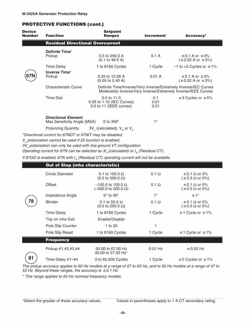
Residual Directional Overcurrent
Definite Time*Pickup 0.5 to 240.0 A 0.1 A 0.1 A or 3%
(0.1 to 48.0 A) ( 0.02 A or 3%)
Time Delay 1 to 8160 Cycles 1 Cycle –1 to +3 Cycles or 1%
Inverse Time*Pickup 0.25 to 12.00 A 0.01 A 0.1 A or 3%
(0.05 to 2.40 A) ( 0.02 A or 3%)
Characteristic Curve Definite Time/Inverse/Very Inverse/Extremely Inverse/IEC CurvesModerately Inverse/Very Inverse/Extremely Inverse/IEEE Curves
Time Dial 0.5 to 11.0 0.1 3 Cycles or 5%0.05 to 1.10 (IEC Curves) 0.010.5 to 11 (IEEE curves) 0.01
Directional ElementMax Sensitivity Angle (MSA) 0 to 359° 1°
Polarizing Quantity 3Vo (calculated), VN or VX
*Directional control for 67NDT or 67NIT may be disabled.VX polarization cannot be used if 25 function is enabled.3Vo polarization can only be used with line-ground VT configuration.Operating current for 67N can be selected as 3Io (calculated) or IN (Residual CT).
If 87GD is enabled, 67N with IN (Residual CT) operating current will not be available.
Out of Step (mho characteristic)
Circle Diameter 0.1 to 100.0 Ω 0.1 Ω 0.1 Ω or 5%(0.5 to 500.0 Ω) ( 0.5 Ω or 5%)
Offset –100.0 to 100.0 Ω 0.1 Ω 0.1 Ω or 5%(–500.0 to 500.0 Ω) ( 0.5 Ω or 5%)
Impedance Angle 0° to 90° 1° 1°
Blinder 0.1 to 50.0 Ω 0.1 Ω 0.1 Ω or 5%(0.5 to 250.0 Ω) ( 0.5 Ω or 5%)
Time Delay 1 to 8160 Cycles 1 Cycle 1 Cycle or 1%
Trip on mho Exit Enable/Disable
Pole Slip Counter 1 to 20 1
Pole Slip Reset 1 to 8160 Cycles 1 Cycle 1 Cycle or 1%
Frequency
Pickup #1,#2,#3,#4 50.00 to 67.00 Hz 0.01 Hz 0.02 Hz40.00 to 57.00 Hz*
Time Delay #1–#4 3 to 65,500 Cycles 1 Cycle 2 Cycles or 1%
The pickup accuracy applies to 60 Hz models at a range of 57 to 63 Hz, and to 50 Hz models at a range of 47 to53 Hz. Beyond these ranges, the accuracy is 0.1 Hz.
* This range applies to 50 Hz nominal frequency models.
†Select the greater of these accuracy values. Values in parentheses apply to 1 A CT secondary rating.
81
78
67N

–9–
M-3425A Generator Protection Relay
PROTECTIVE FUNCTIONS (cont.)Device SetpointNumber Function Ranges Increment Accuracy†
Frequency AccumulationFrequency AccumulationFrequency AccumulationFrequency AccumulationFrequency Accumulation
Bands #1, #2, #3, #4, #5, #6High Band #1 50.00 to 67.00 Hz 0.01 Hz 0.02 Hz
40.00 to 57.00 Hz*
Low Band #1–#6 50.00 to 67.00 Hz 0.01 Hz 0.02 Hz40.00 to 57.00 Hz*
Delay #1–#6 3 to 360,000 Cycles 1 Cycle 2 Cycles or 1%
When using multiple frequency bands, the lower limit of the previous band becomes the upper limit for the next band,i.e., Low Band #2 is the upper limit for Band #3, and so forth. Frequency bands must be used in sequential order, 1 to 6.Band #1 must be enabled to use Bands #2–#6. If any band is disabled, all following bands are disabled.
When frequency is within an enabled band limit, accumulation time starts (there is an internal ten cycle delay prior toaccumulation) and allows the underfrequency blade resonance to be established to avoid unnecessary accumulation oftime. When duration is greater than set delay, the alarm asserts and a target log entry is made.
The pickup accuracy applies to 60 Hz models at a range of 57 to 63 Hz, and 50 Hz models at a range of 47 to 53 Hz.Beyond these ranges, the accuracy is 0.1 Hz.
* This range applies to 50 Hz nominal frequency models.
Rate of Change of Frequency
Pickup #1, #2 0.10 to 20.00 Hz/Sec. 0.01 Hz/Sec. 0.05 Hz/Sec. or 5%
Time Delay #1, #2 3 to 8160 Cycles 1 Cycle + 20 Cycles
Negative SequenceVoltage Inhibit 0 to 99% 1% 0.5%
Phase Differential Current
Pickup #1, #2 0.20 A to 3.00 A 0.01 A 0.1 A or 5%(0.04 to 0.60 A) ( 0.02 A or 5%)
Percent Slope #1, #2 1 to 100% 1% 2%
Time Delay* #1, #2 1 to 8160 Cycles 1 Cycle 1 Cycle or 1%
CT Correction** 0.50 to 2.00 0.01
*When a time delay of 1 cycle is selected, the response time is less than 1–1/2 cycles.
**The CT Correction factor is multiplied by IA,IB,IC.
Ground (zero sequence) Differential Current
Pickup 0.20 to 10.00 A 0.01 A 0.1 A or 5%(0.04 to 2.00 A) ( 0.02 A or 5%)
Time Delay 1 to 8160 Cycles 1 Cycle 1 Cycle or 1%
CT Ratio Correction (RC) 0.10 to 7.99 0.01
The 87GD function is provided primarily for low-impedance grounded generator applications. This functionoperates as a directional differential. If 3I0 or In is extremely small (less than 0.2 secondary Amps), the elementbecomes non-directional.
If 67N function with IN (Residual) operating current is enabled, 87GD will not be available. Also, if 50DT is used forsplit-phase differential, 87GD function will not be available.
†Select the greater of these accuracy values. Values in parentheses apply to 1 A CT secondary rating.
87
87GD
81R
81A

–10–
M-3425A Generator Protection Relay
PROTECTIVE FUNCTIONS (cont.)Device SetpointNumber Function Ranges Increment Accuracy†
IPSlogicTM
IPSlogic uses element pickups, element trip commands, control/status input state changes,output contact close signals to develop 6 programmable logic schemes.
Time Delay #1–#6 1 to 8160 Cycles 1 Cycle 1 Cycle or 1%
Breaker Monitoring
Pickup 0 to 50,000 kA Cycles 1 kA Cycles 1 kACyclesor kA2 Cycles or kA2 Cycles or kA2 Cycles
Time Delay 0.1 to 4095.9 Cycles 0.1 Cycles 1 Cycle or 1%
Timing Method IT or I2T
Preset Accumulators 0 to 50,000 kA Cycles 1 kA CyclePhase A, B, C
The Breaker Monitor feature calculates an estimate of the per-phase wear on the breaker contacts by measuring andintegrating the current (or current squared) through the breaker contacts as an arc.
The per-phase values are added to an accumulated total for each phase, and then compared to a user-programmedthreshhold value. When the threshhold is exceeded in any phase, the relay can set a programmable output contact.
The accumulated value for each phase can be displayed.
The Breaker Monitoring feature requires an initiating contact to begin accumulation, and the accumulation begins afterthe set time delay.
Trip Circuit Monitoring
Time Delay 1 to 8160 Cycles 1 Cycle 1 Cycle or 1%
The AUX input is provided for monitoring the integrity of the trip circuit. This input can be used for nominal trip coilvoltages of 24 V dc, 48 V dc, 125 V dc and 250 V dc.
Nominal Settings
Nominal Voltage 50.0 to 140.0 V 0.1 V —
Nominal Current 0.50 to 6.00 A 0.01 A —
VT Configuration Line-Line/Line-Ground/Line-Ground to Line-Line*
Delta/Wye UnitTransformer Disable/Delta AB/Delta AC
Seal-In Delay 2 to 8160 Cycles 1 Cycle 1 Cycle or 1%
*When Line-Ground to Line-Line is selected, the relay internally calculates the line-line voltages from the line-groundvoltages for all voltage-sensitive functions. This Line-Ground to Line-Line selection should only be used for a VTconnected Line-Ground with a secondary voltage of 69 V (not 120 V).
†Select the greater of these accuracy values. Values in parentheses apply to 1 A CT secondary rating.
IPS
BM
TC

–11–
M-3425A Generator Protection Relay
64F
64B
25
25S
25D
64S
OPTIONAL PROTECTIVE FUNCTIONSDevice SetpointNumber Function Ranges Increment Accuracy†
Sync Check
Dead CheckDead Voltage Limit 0 to 60 V 1 V 0.5 V or ±0.5%
Dead Time Delay 1 to 8160 Cycles 1 Cycle –1 to +3 Cycles or 1%
Sync CheckPhase Angle Window 0° to 90° 1° 1°
Upper Voltage Limit 60 to 140 V 1 V 0.5 V or ±0.5%
Lower Voltage Limit 40 to 120 V 1 V 0.5 V or ±0.5%
Delta Voltage Limit 1.0 to 50.0 V 0.1 V 0.5 V or ±0.5%
Delta Frequency Limit 0.001 to 0.500 Hz 0.001 Hz 0.0007 Hz or ±5%
Sync Check Time Delay 1 to 8160 Cycles 1 Cycle –1 to +3 Cycles or ±1%
Various combinations of input supervised hot/dead closing schemes may be selected. The 25 function cannot beenabled if the 59D function with VX or 67N function with VX is enabled.
Field Ground Protection
Pickup #1, #2 5 to 100 KΩ 1 KΩ 10% or ±1KΩTime Delay #1, #2 1 to 8160 Cycles 1 Cycle ( 2
IF +1) Sec.
Injection Frequency (IF) 0.10 to 1.00 Hz 0.01 Hz
Brush Lift-Off Detection (measuring control circuit)Pickup 0 to 5000 mV 1 mV
Time Delay 1 to 8160 Cycles 1 Cycle ( 2IF +1) Sec.
When 64F is purchased, an external Coupler Module (M-3921) is provided for isolation from dc field voltages.
Figure 8, Field Ground Protection Block Diagram, illustrates a typical connection utilizing the M-3921 FieldGround Coupler. Hardware dimensional and mounting information is shown in Figure 9, M-3921 Field GroundCoupler Mounting Dimensions.
100% Stator Ground Protection by low frequency injection
Pickup 2 to 40 mA 1 mA 1 mATime Delay 1 to 8160 Cycles 1 Cycle 1 Cycle* or 1%
Undervoltage Inhibit 5 to 30 V 1 V 0.5 V to 0.5%
External low frequency generator, band pass filter and current transformer are required for this function. 59D and27TN function should be disabled when the 64S function is enabled. 59N may be applied when this function isenabled.
* Time Delay accuracy in cycles is based on 20 Hz frequency.
†Select the greater of these accuracy values. Values in parentheses apply to 1 A CT secondary rating.

–12–
M-3425A Generator Protection Relay
DescriptionThe M-3425A Generator Protection Relay is suitable for all generator ratings and prime movers. Typicalconnection diagrams are illustrated in Figure 4, M-3425A One-Line Functional Diagram (configured for phasedifferential), and Figure 5, One-Line Functional Diagram (configured for split-phase differential).
Configuration OptionsThe M-3425A Generator Protection Relay is available in either a Base or Comprehensive package ofprotective functions. This provides the user with flexibility in selecting a protective system to best suit theapplication. Additional Optional Protective Functions may be added at the time of purchase at per-functionpricing.
The Human-Machine Interface (HMI) Module, Target Module, or redundant power supply can be selected attime of purchase.
When the Field Ground (64F) Premium Protective Function is purchased, an external coupler module(M-3921) is provided for isolation from the dc field voltages.
When 100% Stator Ground (64S) protection using low-frequency injection is purchased, an external bandpass filter and frequency generator is provided.
Multiple Setpoint Profiles (Groups)The relay supports four setpoint profiles. This feature allows multiple setpoint profiles to be defined for differentpower system configurations or generator operating modes. Profiles can be switched either manually usingthe Human-Machine Interface (HMI), by communications, programmable logic or by control/status inputs.
■■■■■ NOTE: During profile switching, relay operation is disabled for approximately 1 second.
MeteringThe relay provides metering of voltages (phase, neutral and sequence quantities), currents (phase, neutraland sequence quantities), real power, reactive power, power factor and impedance measurements.
Metering accuracies are:
Voltage: 0.5 V or 0.5%, whichever is greater0.8 V or 0.75%, whichever is greater (when both RMS and Line-Ground to Line-Line are
selected)
Current: 5 A rating, 0.1 A or 3%, whichever is greater1 A rating, 0.02 A or 3%, whichever is greater
Power: 0.01 PU or 2% of VA applied, whichever is greater
Frequency: 0.02 Hz (from 57 to 63 Hz for 60 Hz models; from 47 to 53 Hz for 50 Hz models)0.1 Hz beyond 63 Hz for 60 Hz models, and beyond 53 Hz for 50 Hz models
Volts/Hz: 1%
Oscillographic RecorderThe oscillographic recorder provides comprehensive data recording of all monitored waveforms, storing up to472 cycles of data. The total record length is user-configurable from 1 to 16 partitions. The sampling rate is 16times the power system nominal frequency (50 or 60 Hz). The recorder may be triggered using either thedesignated control/status inputs, trip outputs, or using serial communications. When untriggered, the recordercontinuously stores waveform data, thereby keeping the most recent data in memory. When triggered, therecorder stores pre-trigger data, then continues to store data in memory for a user-defined, post-trigger delayperiod. The data records can be stored in either Beckwith Electric format or COMTRADE format.
Target StorageInformation associated with the last 32 trips is stored. The information includes the function(s) operated, thefunctions picked up, input/output status, time stamp, and phase and neutral currents at the time of trip.

–13–
M-3425A Generator Protection Relay
Sequence of Events LogThe Sequence of Events Log records relay element status, I/O status, measured values and calculated valuestime stamped with 1 ms resolution at user-defined events. The Sequence of Events Log includes 512 of themost recently recorded relay events. The events and the associated data is available for viewing utilizing theM-3820D IPScom Communications Software.
CalculationsCurrent and Voltage RMS Values: Uses Discrete Fourier Transform algorithm on sampled voltage and currentsignals to extract fundamental frequency phasors for relay calculations. RMS calculation for the 50, 51N, 59and 27 functions, and the 24 function are obtained using the time domain approach to obtain accuracy over awide frequency band. When the RMS option is selected, the magnitude calculation for 59 and 27 functions isaccurate over a wide frequency range (10 to 80 Hz). When the DFT option is selected, the magnitudecalculation is accurate near nominal frequency (50 Hz/60 Hz) but will degrade outside the nominal frequency.For 50 and 51N functions the DFT is used when the frequency is 55 Hz to 65 Hz for 60 Hz (nominal) and 45 Hzto 55Hz for 50 Hz (nominal), outside of this range RMS calculation is used.
Power Input OptionsNominal 110/120/230/240 V ac, 50/60 Hz, or nominal 110/125/220/250 V dc. Operates properly from 85 V acto 265 V ac and from 80 V dc to 312.5 V dc. Withstands 300 V ac or 315 V dc for 1 second. Nominal burden 40VA at 120 V ac/125 V dc.
Nominal 24/48 V dc, operates properly from 18 V dc to 56 V dc, withstands 65 V dc for 1 second. Burden 25 VAat 24 V dc and 30 VA at 48 V dc.
An optional redundant power supply is available for units that are purchased without the expanded I/O.
For those units purchased with the expanded I/O, the unit includes two power supplies which are required topower the relay. Burden (nominal) 46 VA @120 V ac.
Sensing InputsFive Voltage Inputs: Rated for a nominal voltage of 50 V ac to 140 V ac at 60 Hz or 50 Hz. Will withstand 240V continuous voltage and 360 V for 10 seconds. Source voltages may be line-to-ground or line-to-lineconnected. Phase sequence ABC or ACB is software selectable. Voltage transformer burden less than 0.2 VAat 120 V ac.
Seven Current Inputs: Rated nominal current (IR) of 5.0 A or 1.0 A at 60 Hz or 50 Hz. Will withstand 3I
Rcontinuous current and 100I
R for 1 second. Current transformer burden is less than 0.5 VA at 5 A, or 0.3 VA
at 1 A.
Control/Status InputsThe control/status inputs, INPUT1 through INPUT6, can be programmed to block any relay protective function,to trigger the oscillograph recorder, to operate one or more outputs or can be an input into IPSlogicTM. Toprovide breaker status LED indication on the front panel, the INPUT1 control/status input contact must beconnected to the 52b breaker status contact.
The optional expanded I/O includes an additional 8 programmable control/status inputs (INPUT7 throughINPUT14).
▲ CAUTION: The control/status inputs should be connected to dry contacts only, and are internally connected(wetted) with a 24 V dc power supply.
Output ContactsAny of the functions can be individually programmed to activate any one or more of the eight programmableoutput contacts OUTPUT1 through OUTPUT8. Any output contact can also be selected as pulsed or latched.IPSlogic can also be used to activate an output contact.
The optional expanded I/O includes an additional 15 programmable output contacts (OUTPUT9 throughOUTPUT23). These contacts are configurable only using IPScom software.
The eight output contacts (six form ‘a’ and two form ‘c’), the power supply alarm output contact (form ‘b’), theself-test alarm output contact (form ‘c’) and the optional 15 expanded I/O output contacts (form 'a') are all ratedper ANSI/IEEE C37.90-1989 for tripping. Make 30 A for 0.2 seconds, carry 8 A, break 6 A at 120 V ac, break0.5 A at 48 V dc; 0.3 A, 125 V dc; 0.2 A, 250 V dc with L/R=40 mSec.
–14–
M-3425A Generator Protection Relay
IPSlogicThis feature can be programmed utilizing the IPScom® Communications Software. IPSlogic takes the contactinput status and function status, and by employing (OR, AND, and NOT) boolean logic and a timer, canactivate an output or change setting profiles.
Target/Status Indicators and ControlsThe RELAY OK LED reveals proper cycling of the microcomputer. The BRKR CLOSED LED will turn on whenthe breaker is closed (when the 52b contact input is open). The OSC TRIG LED indicates that oscillographicdata has been recorded in the unit's memory. The TARGET LED will turn on when any of the relay functionsoperate. Pressing and releasing the TARGET RESET button resets the target LED if the conditions causingthe operation have been removed. Holding the TARGET RESET button displays the present pickup status ofthe relay functions. The PS1 and PS2 LEDs will remain on as long as power is applied to the unit and the powersupply is operating properly. TIME SYNC LED illuminates when valid IRIG-B signal is applied and timesynchronization has been established.
CommunicationCommunications ports include rear panel RS-232 and RS-485 ports, a front panel RS-232 port, a rear-panelIRIG-B port and an Ethernet port (optional). The communications protocol implements serial, byte-oriented,asynchronous communication, providing the following functions when used with the Windows™-compatibleM-3820D IPScom® Communications Software. MODBUS and BECO 2200 protocols are supported providing:
• Interrogation and modification of setpoints
• Time-stamped information for the 32 most recent trips
• Real-time metering of all quantities measured
• Downloading of recorded oscillographic data and Sequence of Events Recorder data.
When the optional Ethernet port is purchased it also provides MODBUS over TCP/IP and BECO2200 overTCP/IP protocols.
IRIG-BThe M-3425A Generator Protection Relay can accept either modulated or demodulated IRIG-B time clocksynchronization signal. The IRIG-B time synchronization information is used to correct the hour, minutes,seconds, and milliseconds information.
HMI Module (optional)Local access to the relay is provided through an optional M-3931 HMI (Human-Machine Interface) Module,allowing for easy-to-use, menu-driven access to all functions via six buttons and a 2-line by 24 characteralphanumeric vacuum florescent display. Features of the HMI Module include :
• User-definable access codes allow three levels of security
• Interrogation and modification of setpoints
• Time-stamped information for the 32 most recent trips
• Real-time metering of all quantities measured
Target Module (optional)An optional M-3925A Target Module provides 24 target and 8 output LEDs. Appropriate target LEDs will lightwhen the corresponding function operates. The targets can be reset with the TARGET RESET pushbutton.The OUTPUT LEDs indicate the status of the programmable output relays.

–15–
M-3425A Generator Protection Relay
Temperature Controller MonitoringAny Temperature Controller equipped with a contact output may be connected to the M-3425A and controlledby the relay's IPSlogic function. Figure 1 is an example of a typical Temperature Controller Monitoringapplication.
TemperatureController
Omron E5C2P.D. 750
or equivalent
IN X
IN RTN
M-3425A
IPSlogic
Alarm/TripR1
C
R2
Figure 1 Typical Temperature Controller Monitoring Application
I/O Expansion (optional)Optional I/O Expansion provides an additional 15 form 'a' output contacts and an additional 8 control/statusinputs. Output LEDs indicate the status of the output relays.
Tests and StandardsThe relay complies with the following type tests and standards:
Voltage Withstand
Dielectric WithstandIEC 60255-5 3,500 V dc for 1 minute applied to each independent circuit to earth
3,500 V dc for 1 minute applied between each independent circuit1,500 V dc for 1 minute applied to IRIG-B circuit to earth1,500 V dc for 1 minute applied between IRIG-B to each independent circuit1,500 V dc for 1 minute applied between RS-485 to each independent circuit
Impulse VoltageIEC 60255-5 5,000 V pk, +/- polarity applied to each independent circuit to earth
5,000 V pk, +/- polarity applied between each independent circuit1.2 by 50 μs, 500 ohms impedance, three surges at 1 every 5 seconds
Insulation ResistanceIEC 60255-5 > 40 Megaohms

–16–
M-3425A Generator Protection Relay
Electrical Environment
Electrostatic Discharge TestEN 60255-22-2 Class 4 (8 kV)—point contact discharge
EN 60255-22-2 Class 4 (15kV)–air discharge
Fast Transient Disturbance TestEN 60255-22-4 Class A (4 kV, 2.5 kHz)
Surge Withstand CapabilityANSI/IEEE 2,500 V pk-pk oscillatory applied to each independent circuit to earthC37.90.1- 2,500 V pk-pk oscillatory applied between each independent circuit1989 5,000 V pk Fast Transient applied to each independent circuit to earth
5,000 V pk Fast Transient applied between each independent circuit
ANSI/IEEE 2,500 V pk-pk oscillatory applied to each independent circuit to earthC37.90.1- 2,500 V pk-pk oscillatory applied between each independent circuit 2002 4,000 V pk Fast Transient burst applied to each independent circuit to earth
4,000 V pk Fast Transient burst applied between each independent circuit
■ NOTE: The signal is applied to the digital data circuits (RS-232, RS-485, IRIG-B, Ethernet communicationport and field ground coupling port) through capacitive coupling clamp.
Radiated SusceptibilityANSI/IEEE 25-1000 Mhz @ 35 V/mC37.90.2
Output ContactsANSI/IEEE Make 30 A for 0.2 seconds, off for 15 seconds for 2,000 operations, per Section 6.7.1, TrippingC37.90.0 Output Performance Requirements
Atmospheric Environment
TemperatureIEC 60068-2-1 Cold, –20° CIEC 60068-2-2 Dry Heat, +70° CIEC 60068-2-3 Damp Heat, +40° C @ 93% RH
Mechanical Environment
VibrationIEC 60255-21-1Vibration response Class 1, 0.5 g
Vibration endurance Class 1, 1.0 g
IEC 60255-21-2Shock Response Class 1, 5.0 gShock Withstand Class 1, 15.0 gBump Endurance Class 1, 10.0 g
–17–
M-3425A Generator Protection Relay
ComplianceUL-Listed per 508 – Industrial Control Equipment
UL-Listed Component per 508A Table SA1.1 Industrial Control Panels
CSA-Certified per C22.2 No. 14-95 – Industrial Control Equipment
CE Safety Directive – EN61010-1:2001, CAT II, Pollution Degree 2 (Pending for expanded I/O option.)
PhysicalWithout Optional Expanded I/O
Size: 19.00" wide x 5.21" high x 10.20" deep (48.3 cm x 13.2 cm x 25.9 cm)
Mounting: The unit is a standard 19", semiflush, three-unit high, rack-mount panel design, conforming toANSI/EIA RS-310C and DIN 41494 Part 5 specifications. Vertical or horizontal panel-mount options areavailable.
Approximate Weight: 17 lbs (7.7 kg)
Approximate Shipping Weight: 25 lbs (11.3 kg)
With Optional Expanded I/O
Size: 19.00" wide x 6.96" high x 10.2" deep (48.3 cm x 17.7 cm x 25.9 cm)
Mounting: The unit is a standard 19", semiflush, four-unit high, rack-mount panel design, conforming to ANSI/EIA RS-310C and DIN 41494 Part 5 specifications. Vertical or horizontal panel-mount options are available.
Approximate Weight: 19 lbs (8.6 kg)
Approximate Shipping Weight: 26 lbs (11.8 kg)
Patent & WarrantyThe M-3425A Generator Protection Relay is covered by U.S. Patents 5,592,393 and 5,224,011.
The M-3425A Generator Protection Relay is covered by a five year warranty from date of shipment.
Specification subject to change without notice.
External ConnectionsM-3425A external connection points are illustrated in Figures 2 and 3.

–18–
M-3425A Generator Protection Relay
�����������
�����������
������������
������
������
���
���
���
��
��
���
����
�����
������
�
��� ������!!�
��"���#$
�����
���%&��'��������
�������
!�!(���(����
�������
�')
�')
���������
������
��������������� ���������������������
����(����
&����� *�������&��'�����������+�������������
�'��%
���,
������
������
���
�-�
�����
���
��
���
����
��'�����
�
�
��
(�
�������
��
���
��
(.
��
��
�
���
��
�
.
!"
�
�
�
�
�
���
����
����
����������������
�"�"�"�"�!�!�!�!
������������
������������
��
����������������
��������
�
��
���!
�"��
�
����
����
���!
�"
���
�/��
����
���
����
,!
�� 0
�� �
��
�!�"
����
���
�� ��
��
����
�
����
����
���!
����
��"
����
��
��� (�
�����
����
��
��
���
*
*���� ��
���
*
�����12�(�����22222222222222222222222222222222222222222222����&���12�(��
(.
.(
����
���(
��� �
���
�(��
�
��������� �
�(������-�')
������
����
����������3
�
���"���
����-�
�
Fig
ure
2E
xter
nal C
onne
ctio
ns (
Wit
hout
Opt
iona
l Exp
ande
d I/
O)
■■■■ ■N
OT
ES
:
1.S
ee M
-342
5A In
stru
ctio
n B
ook
Sec
tion
2.3,
Set
poin
ts a
nd T
ime
Set
tings
, sub
sect
ion
for
64B
/F F
ield
Gro
und
Pro
tect
ion.
2.B
efor
e m
akin
g co
nnec
tions
to th
e T
rip C
ircui
t Mon
itorin
g in
put,
see
M-3
425A
Inst
ruct
ion
Boo
k S
ectio
n 5.
5, C
ircui
t Boa
rd S
witc
hes
and
Jum
pers
,fo
r th
e in
form
atio
n re
gard
ing
setti
ng T
rip C
ircui
t Mon
itorin
g in
put v
olta
ge. C
onne
ctin
g a
volta
ge o
ther
than
the
volta
ge th
at th
e un
it is
con
figur
edto
may
res
ult i
n m
is-o
pera
tion
or p
erm
anen
t dam
age
to th
e un
it.
3.8888 8
WA
RN
ING
: ON
LY
DR
Y C
ON
TA
CT
S m
ust
be
con
nec
ted
to
inp
uts
(te
rmin
als
5 th
rou
gh
10
wit
h 1
1 co
mm
on
) b
ecau
se t
hes
e co
nta
ctin
pu
ts a
re in
tern
ally
wet
ted
. Ap
plic
atio
n o
f ex
tern
al v
olt
age
on
th
ese
inp
uts
may
res
ult
in d
amag
e to
th
e u
nit
s.
4.8888 8
WA
RN
ING
: T
he
pro
tect
ive
gro
un
din
g t
erm
inal
mu
st b
e co
nn
ecte
d t
o a
n e
arth
ed g
rou
nd
an
y ti
me
exte
rnal
co
nn
ecti
on
s h
ave
bee
nm
ade
to t
he
un
it.

–19–
M-3425A Generator Protection Relay
�� ���
����
����
����
����
�!
"�
����
����
������
�����
����
��'�����
����
!�!(���(����
��"���#$
�����
��� ������!!�
���%&��'��������
�������
&����� *�������&��'�����������+�������������
�'��%
��������������� ���������������������
!�!�
!!�
!"��
����
����
����
�!�"
"�"
"�"�
"�"�
"�"!
"""�
�-�
����������������
������������
���������!�!�!�!
�"�"�"�"��������
����������������
���
��
������
�!��
�"
�������
�� �
��
��� (�
��
���
�
�� ��
� �
��
�
�
�����
����
.(
(�
.��
��
��
�
���,
�
���
������
����
���
�����
��� �
�����
�!
��
"
����
����
��"
�����������
�����������
����
���
����
����
�!��
��"
����
��
��
��
���
�
��� �
����(����
������
/�� ,
�!
�������
����
���!
��
���!
��"
����
��
����
0��
��
�������
��
��
�
��
��
�
�!��
����
��
����
�"��
���
����
���
��
�
����
"
����
�!�"
!!�
!�!�
!�!�
��
�
��
��
��
��
"!
*
��*
���
��
��
*
���
���
���
���
�(�
��
���
���
��
( ���
..
((
��������� �
�(������-�')
�����12�(�����22222222222222222222222����&���12�(��
�')
�')
���������
������
������������
������
���
��
���
3�
���
��
����
����� �
���
����
�
Fig
ure
3E
xter
nal C
onne
ctio
ns (
Wit
h O
ptio
nal E
xpan
ed I
/O)
■■■■ ■N
OT
ES
:
1.S
ee M
-342
5A In
stru
ctio
n B
ook
Sec
tion
2.3,
Set
poin
ts a
nd T
ime
Set
tings
, sub
sect
ion
for
64B
/F F
ield
Gro
und
Pro
tect
ion.
2.B
efor
e m
akin
g co
nnec
tions
to th
e T
rip C
ircui
t Mon
itorin
g in
put,
see
M-3
425A
Inst
ruct
ion
Boo
k S
ectio
n 5.
5, C
ircui
t Boa
rd S
witc
hes
and
Jum
pers
,fo
r th
e in
form
atio
n re
gard
ing
setti
ng T
rip C
ircui
t Mon
itorin
g in
put v
olta
ge. C
onne
ctin
g a
volta
ge o
ther
than
the
volta
ge th
at th
e un
it is
con
figur
edto
may
res
ult i
n m
is-o
pera
tion
or p
erm
anen
t dam
age
to th
e un
it.
3.8888 8
WA
RN
ING
: ON
LY
DR
Y C
ON
TA
CT
S m
ust
be
con
nec
ted
to in
pu
ts (t
erm
inal
s 5
thro
ug
h 1
0 w
ith
11
com
mo
n a
nd
term
inal
s 68
thro
ug
h75
wit
h 6
6 an
d 6
7 co
mm
on
) b
ecau
se t
hes
e co
nta
ct i
np
uts
are
in
tern
ally
wet
ted
. A
pp
licat
ion
of
exte
rnal
vo
ltag
e o
n t
hes
e in
pu
ts m
ayre
sult
in d
amag
e to
th
e u
nit
s.
4.8888 8
WA
RN
ING
: T
he
pro
tect
ive
gro
un
din
g t
erm
inal
mu
st b
e co
nn
ecte
d t
o a
n e
arth
ed g
rou
nd
an
y ti
me
exte
rnal
co
nn
ecti
on
s h
ave
bee
nm
ade
to t
he
un
it.

–20–
M-3425A Generator Protection Relay
50DT
Utility System
52Unit
52Gen
50BFPh
87
492132 504078 60FL 51V 50/27
27
81R 81 27 59 24
64F 64B
M-3921+
-
CT
VT
M-3425A
87GD 50N50
BFN 51N
R
64S27TN
27
32R
High-impedance Grounding with ThirdHarmonic 100% Ground Fault Protection
Low-impedance Grounding with Ground Differentialand Overcurrent Stator Ground Fault Protection
These functions are available inthe Comprehensive Package. Asubset of these functions are alsoavailable in a Base Package.
This function is available as aoptional protective function.
This function provides control forthe function to which it points.
M-3425A TypicalConnection Diagram
25
59D
VT (Note 1)
Targets(Optional)
Integral HMI(Optional)
Metering
Waveform Capture
IRIG-B
Front RS232Communication
Multiple SettingGroups
Programmable I/O
Self Diagnostics
Dual Power Supply(Optional)
Rear Ethernet Port (Optional)
Rear RS-485Communication
BreakerMonitoring
Trip CircuitMonitoring
67N67N Polarization(Software Select)
81A
50N50BFN 51N
46
59X
59N
3VO (Calculated)VX
VN
3IO
IN
67N Operating Current(Software Select)
VT (Note 1)
(Note 3)
(Note 5)
CT (Residual)(Note 4)
59D Line SideVoltage
(Software Select)
VX3VO (Calculated)
CT (Neutral)(Notes 2 & 5)
CTM
(Metering)
M
(Metering)
Rear RS232Communication
Event Log
■ NOTES:1. When 25 function is enabled, 59X, 59D with V
X and 67N with V
X are not available, and vice versa.
2. When 67N function with IN (Residual) operating current is enabled, 87GD is not available, and vice
versa.3. When VT source is used as a turn-to-turn fault protection device (See M-3425A Instruction Book,
Chapter 2, Application, for additional 59X applications.)4. The current input I
N can be connected either from neutral current or residual current.
5. The 50BFN, 50N, 51N, 59D, 67N (with IN or V
N) and 87GD functions are unavailable when the 64S
function has been purchased. See the M-3425A Instruction Book for connection details.
Figure 4 One-Line Functional Diagram (Configured with Phase Differential)

–21–
M-3425A Generator Protection Relay
Utility System
52Unit
52Gen
81R 81 59 27 24
M-3921+
-
VT
CT
M-3425A
50N 51N
R
CT
27
32R
High-impedance Grounding with ThirdHarmonic 100% Ground Fault Protection
Low-impedance Grounding withOvercurrent Stator Ground Fault Protection
These functions are available inthe Comprehensive Package. Asubset of these functions are alsoavailable in a Base Package.
This function is available as aoptional protective function.
This function provides control forthe function to which it points.
M-3425A TypicalConnection Diagram(Configured for Split-Phase Differential)
25
59D
50DT
67N
Targets(Optional)
Integral HMI(Optional)
Metering
Waveform Capture
IRIG-B
Front RS232Communication
Multiple SettingGroups
Programmable I/O
Self Diagnostics
Dual Power Supply(Optional)
Rear EthernetPort (Optional)
Rear RS-485Communication
BreakerMonitoring
Trip CircuitMonitoring
27TN
81A
46492132 504078 60FL 51V 50/27
2764F 64B
59X
64S 59N
CT (Residual)(Note 5)
VT (Note 1)
VT (Note 1)
67N Polarization(Software Select)
3VO (Calculated)
VX
VN
(Note 2)
CT (Note 3)
(Note 4)
59D Line SideVoltage
(Software Select)
VX 3VO (Calculated)
CT (Neutral)(Note 5)
M
(Metering)
M
(Metering)
Rear RS232Communication
Event Log
■ NOTES:
1. When 25 function is enabled, 59X, 59D with VX and 67N with V
X are not available, and vice versa.
2. When used as a turn-turn fault protection device.
3. CTs are connected for split-phase differential current.
4. 67N operating current can only be selected to IN
(Residual) for this configuration.
5. The current input (IN) can be connected either from neutral current or residual current.
6. The 50BFN, 50N, 51N, 59D, 67N (with IN or V
N) and 87GD functions are unavailable when the 64S
function has been purchased. See the M-3425A Instruction Book for connection details.
Figure 5 One-Line Functional Diagram (configured for split-phase diffential)

–22–
M-3425A Generator Protection Relay
������������� �
������������� �
������������
�����������
������������
������������
����������
����������
���������������������� �!�"����#�$$�$
������%�&�'(�$���$����)��*+(�$���(����*(���'(�(�$�
���4���5
,(���-�(.
�����������/��������������0��1�/2
Figure 6 Horizontal Mounting Dimensions (Without Expanded I/O)
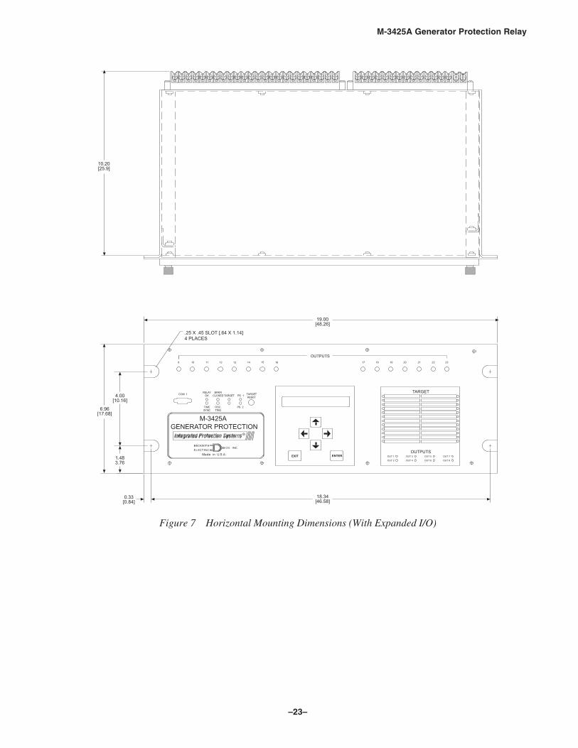
■ NOTE: Panels for vertical mounting are available (See Figure 8).
–23–
M-3425A Generator Protection Relay
���2�2���2����24���2�2����5�2������
�"�4�����5
��"�4�!���5
��4����5
������!�
���4���"5
���4���5
�����4�����5
�/67 89 ������
�+������
�%����+
��� � �� �
�� �
��%�������
�������
��� ��
�
�������� ��
�(����� ��������2����������
��" � �� �� �� �� ��
��������! �"�� � �� �� ��
�
�� ���� ��
��
'�
� ��� �
%�� &�
���� ����� ���2�
���2�
���2�
���2�
���2�
���2�
����������2!
���2�
��� ��
Figure 7 Horizontal Mounting Dimensions (With Expanded I/O)
–24–
M-3425A Generator Protection Relay
03����� �-(���*� �!�"����#�$$�$
������%�&�'(�$���$����)��*+(�$���(���*(���'(�(�$�
���4���5
�����4�����5
����4��!�5 ��!�
4����5
�"�4�����5 �!���
4���"!5�0#:/;
���"4����5
����4�����5
�!��4�����5
�� �
��24���52<��!24���5����2��<
,(���-�(.
,4�0!!45&4&�� �0 ��6�45,4�7�8���954��!0 5�
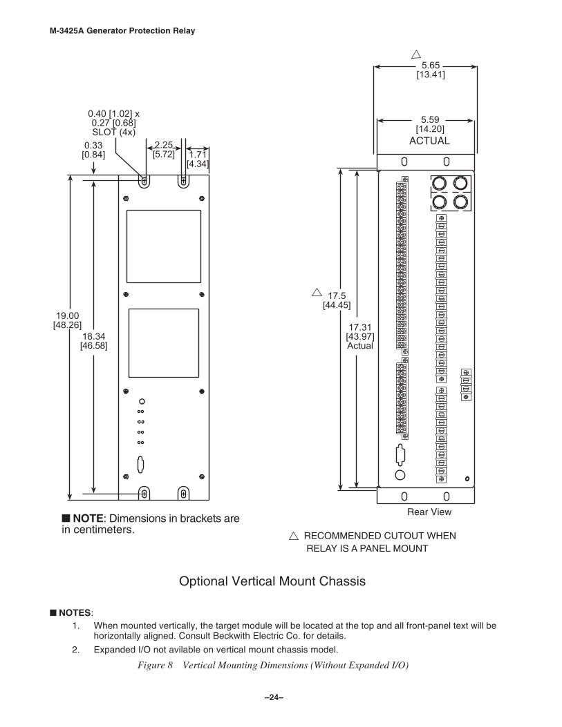
■ NOTES:1. When mounted vertically, the target module will be located at the top and all front-panel text will be
horizontally aligned. Consult Beckwith Electric Co. for details.
2. Expanded I/O not avilable on vertical mount chassis model.
Figure 8 Vertical Mounting Dimensions (Without Expanded I/O)
–25–
M-3425A Generator Protection Relay
�����������
�����������
�����������
�������
���������
�����������
����������
���������
����������
����������
���������
�������
: ;��������1�<2
: ;��������1�<2
,4�0!!45&4&�� �0 ���5&,&��� 58��954��!=����
,4�0!!45&4&�� �0 ��� 58��954��!=�����14<�45&4&�8>02
�0�4,5�4%��<<?����
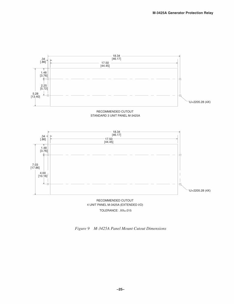
Figure 9 M-3425A Panel Mount Cutout Dimensions
–26–
M-3425A Generator Protection Relay
M-3921 Field Ground Coupler
�������������� ������
���������
@�����A��������������
�B���� �C�A��������
��D��� ��!���"������������!!��D
��#��A��$��E% ��&�'(
A�����) ��*����@��"�
�*�F�A�����G��!*
�+���������H!��"
A��,�����
G��!*�!
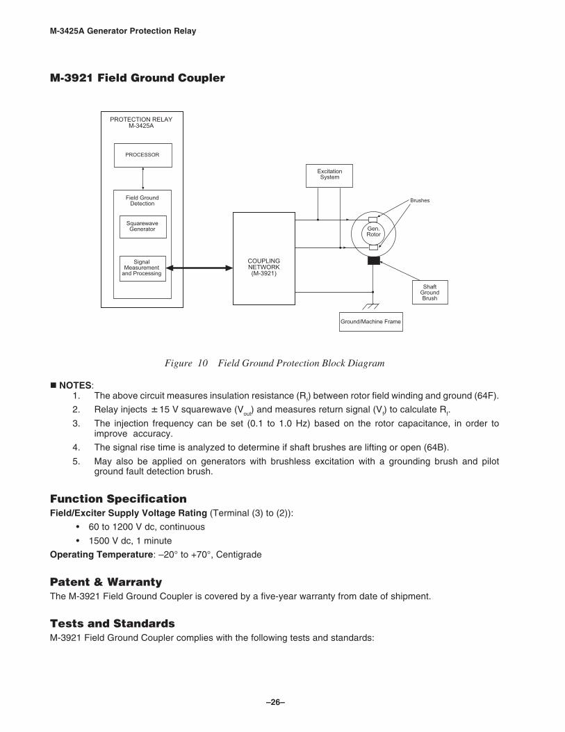
Figure 10 Field Ground Protection Block Diagram
NOTES:1. The above circuit measures insulation resistance (R
f) between rotor field winding and ground (64F).
2. Relay injects 15 V squarewave (Vout
) and measures return signal (Vf) to calculate R
f.
3. The injection frequency can be set (0.1 to 1.0 Hz) based on the rotor capacitance, in order toimprove accuracy.
4. The signal rise time is analyzed to determine if shaft brushes are lifting or open (64B).
5. May also be applied on generators with brushless excitation with a grounding brush and pilotground fault detection brush.
Function SpecificationField/Exciter Supply Voltage Rating (Terminal (3) to (2)):
• 60 to 1200 V dc, continuous
• 1500 V dc, 1 minute
Operating Temperature: –20° to +70°, Centigrade
Patent & WarrantyThe M-3921 Field Ground Coupler is covered by a five-year warranty from date of shipment.
Tests and StandardsM-3921 Field Ground Coupler complies with the following tests and standards:

–27–
M-3425A Generator Protection Relay
Voltage Withstand
Isolation4 kV ac for 1 minute, all terminals to case
Impulse VoltageIEC 60255–5, 5,000 V pk, 1.2 by 50 μs, 0.5 J, 3 positive and 3 negative impulses at 5 second
intervals per minute
Electrical InterferenceElectrostatic Discharge TestIEC 61000-4-2 Class 4 (8 kV)—point contact discharge
Fast Transient Disturbance TestsIEC 61000-4-4 Class 4 (4 kV, 2.5 kHz)
Surge Withstand CapabilityANSI/IEEE 2,500 V pk-pk oscillatory applied to each independent circuit to earthC37.90.1- 2,500 V pk-pk applied between each independent circuit1989 5,000 V pk Fast Transient applied to each independent circuit to earth
5,000 V pk Fast Transient applied between each independent circuit
■ NOTE: See also M-3425A Surge Withstand Capability test standards, ANSI/IEEE C37.90.2-2002.
Radiated SusceptibilityANSI/IEEE 25-1000 Mhz @ 20 V/mC37.90.2
Atmospheric EnvironmentIEC 60068–2–1 Cold, –20° CIEC 60068–2–2 Dry Heat, +70° CIEC 60068–2–3 Damp Heat, +40° C @ 93% RH
Enclosure ProtectionNEMA 1, IEC IPC-65

800-3425A-SP-01MC5 1/06© 2001 Beckwith Electric Co.Printed in U.S.A. (#01-67) (04.25.03)
ISO
9001
:2000
Regist
ered
BECKWITH ELECTRIC CO., INC.6190 - 118th Avenue North • Largo, Florida 33773-3724 U.S.A.
PHONE (727) 544-2326 • FAX (727) 546-0121E-MAIL [email protected] PAGE www.beckwithelectric.com
.18 DIA [0.46] 4 HOLES
MOUNTING PATTERNWITHOUT TABS
Field GroundCoupler4.72 [11.99]
7.87 [19.99] 2.96 REF [7.52]
3.54 [9.0]
�NOTE: Dimensions in brackets are in centimeters.
7.40[18.79]
9.06 [23.01]
3.54 [9.0]
.18 DIA [0.46] 4 X
��� ������������
���%&��'
�/672892������
M-3921
Figure 11 M-3921 Field Ground Coupler Mounting Dimensions