geomatics engineering credit hrs: 2 · principle of compass surveying • the principle of compass...
TRANSCRIPT
GEOMATICS ENGINEERING
CHAPTER 3
Compass Surveying and Traversing
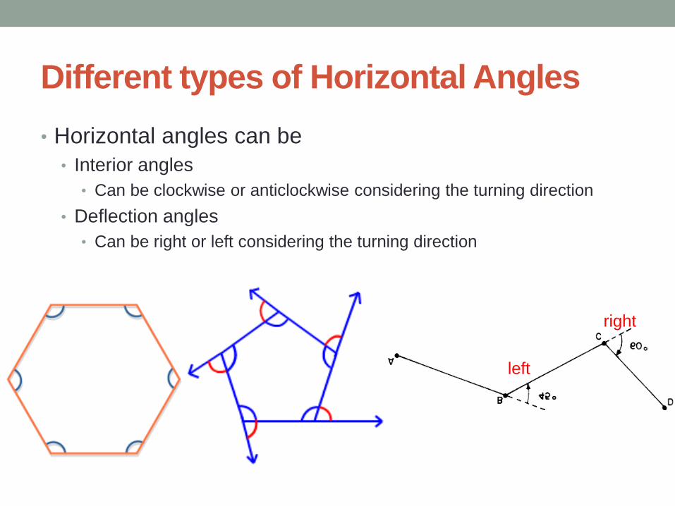
Different types of Horizontal Angles
• Horizontal angles can be
• Interior angles
• Can be clockwise or anticlockwise considering the turning direction
• Deflection angles
• Can be right or left considering the turning direction
left
right

Direction of a Line
• Direction of a line is the horizontal angle from a reference line called
the meridian.
• There are four basic types of meridians:
• Astronomic meridian
• It is an imaginary line on the earth’s surface passing through the north-
south geographical poles.
• Magnetic meridian
• It is direction of the vertical plane shown by a freely suspended magnetic
needle.
• Grid meridian
• A line through a point parallel to the central meridian or y-axis of a
rectangular coordinate system
• Arbitrary meridian
• An arbitrary chosen line with a direction value assigned by the observer.
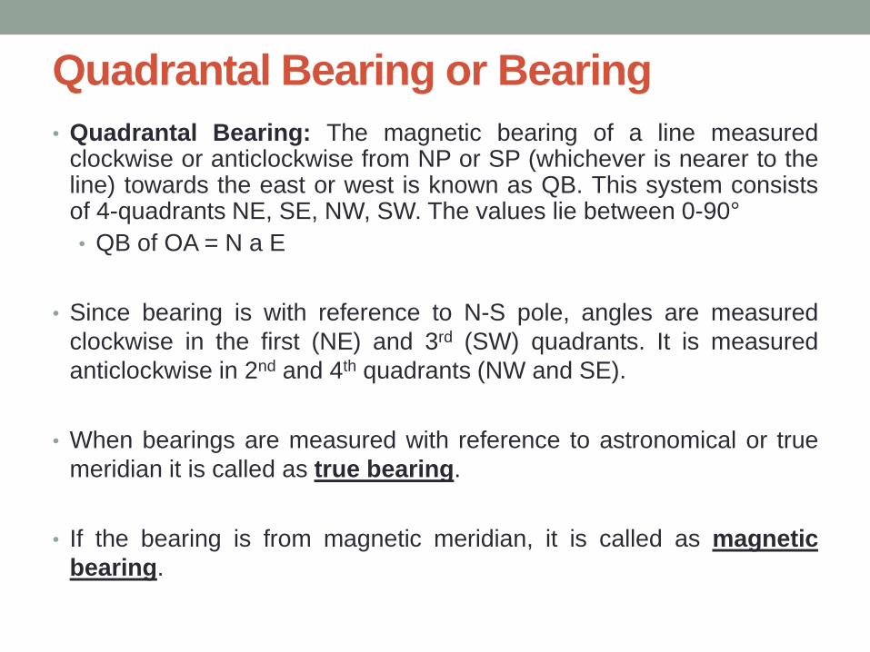
Quadrantal Bearing or Bearing
• Quadrantal Bearing: The magnetic bearing of a line measured clockwise or anticlockwise from NP or SP (whichever is nearer to the line) towards the east or west is known as QB. This system consists of 4-quadrants NE, SE, NW, SW. The values lie between 0-90°
• QB of OA = N a E
• Since bearing is with reference to N-S pole, angles are measured
clockwise in the first (NE) and 3rd (SW) quadrants. It is measured
anticlockwise in 2nd and 4th quadrants (NW and SE).
• When bearings are measured with reference to astronomical or true
meridian it is called as true bearing.
• If the bearing is from magnetic meridian, it is called as magnetic
bearing.
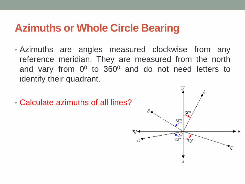
Azimuths or Whole Circle Bearing
• Azimuths are angles measured clockwise from any
reference meridian. They are measured from the north
and vary from 00 to 3600 and do not need letters to
identify their quadrant.
• Calculate azimuths of all lines?
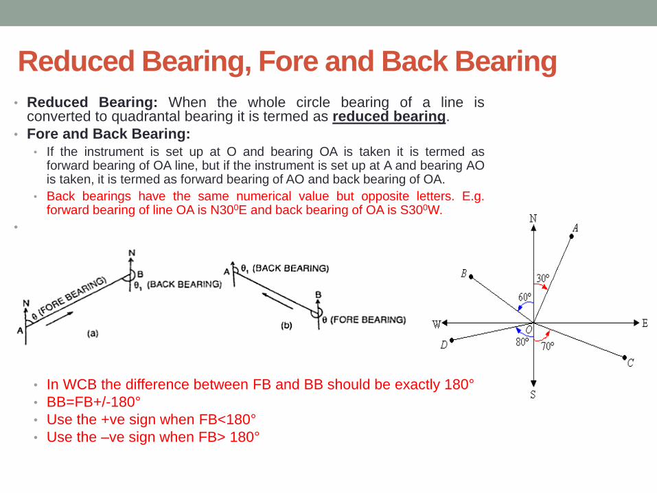
• Reduced Bearing: When the whole circle bearing of a line is converted to quadrantal bearing it is termed as reduced bearing.
• Fore and Back Bearing:
• If the instrument is set up at O and bearing OA is taken it is termed as forward bearing of OA line, but if the instrument is set up at A and bearing AO is taken, it is termed as forward bearing of AO and back bearing of OA.
• Back bearings have the same numerical value but opposite letters. E.g. forward bearing of line OA is N300E and back bearing of OA is S300W.
•
• In WCB the difference between FB and BB should be exactly 180°
• BB=FB+/-180°
• Use the +ve sign when FB<180°
• Use the –ve sign when FB> 180°
Reduced Bearing, Fore and Back Bearing
Summary: Bearings to Azimuths
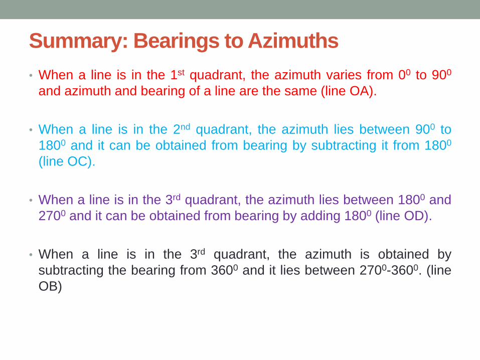
• When a line is in the 1st quadrant, the azimuth varies from 00 to 900
and azimuth and bearing of a line are the same (line OA).
• When a line is in the 2nd quadrant, the azimuth lies between 900 to
1800 and it can be obtained from bearing by subtracting it from 1800
(line OC).
• When a line is in the 3rd quadrant, the azimuth lies between 1800 and
2700 and it can be obtained from bearing by adding 1800 (line OD).
• When a line is in the 3rd quadrant, the azimuth is obtained by
subtracting the bearing from 3600 and it lies between 2700-3600. (line
OB)

Azimuth (WCB) to Bearing
• Convert the following azimuths to bearings.
• OA = 50020’
• OB = 154025’
• OC = 261025’
• OD =312038’
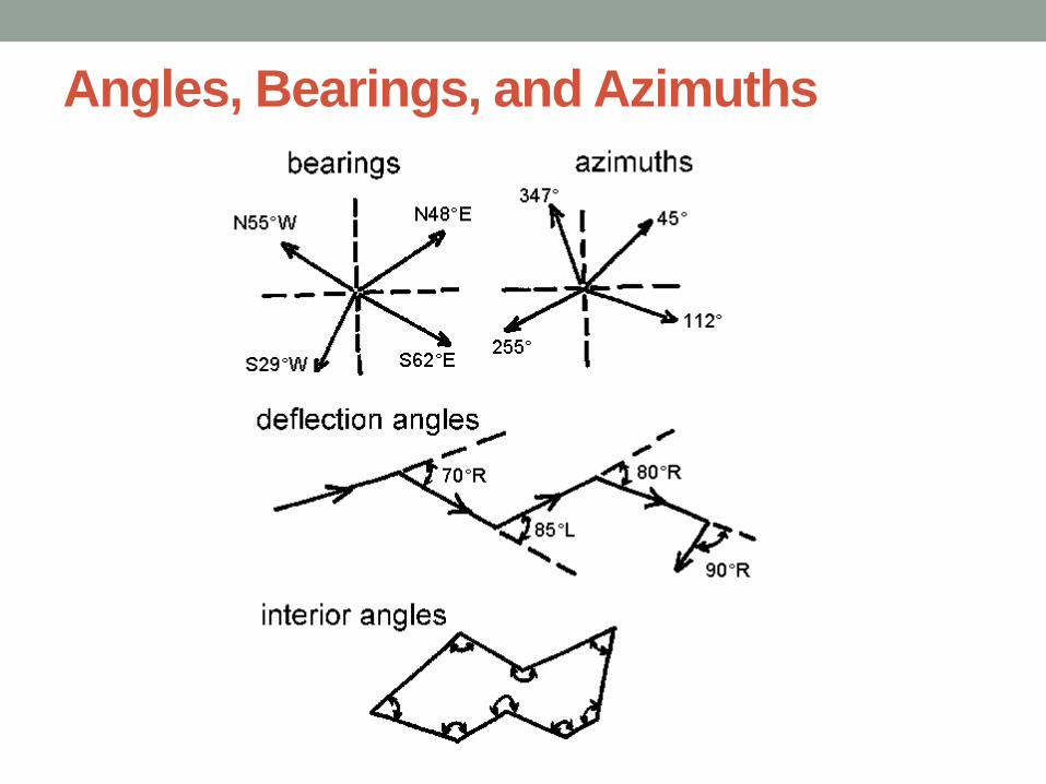
Angles, Bearings, and Azimuths
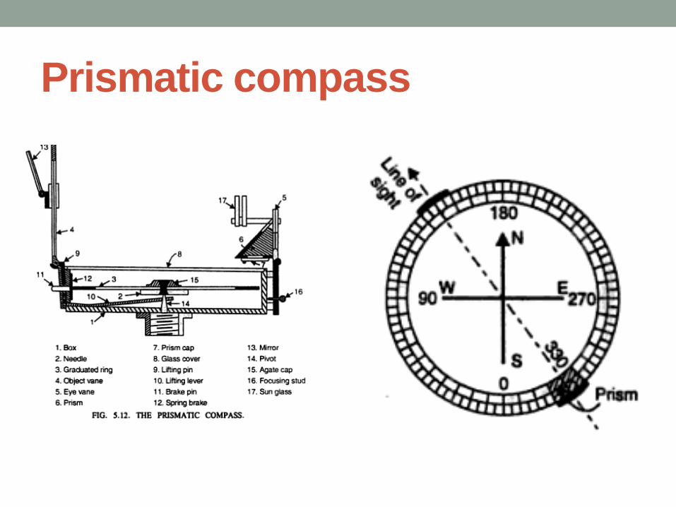
Prismatic compass
Compass traversing: Important Definition
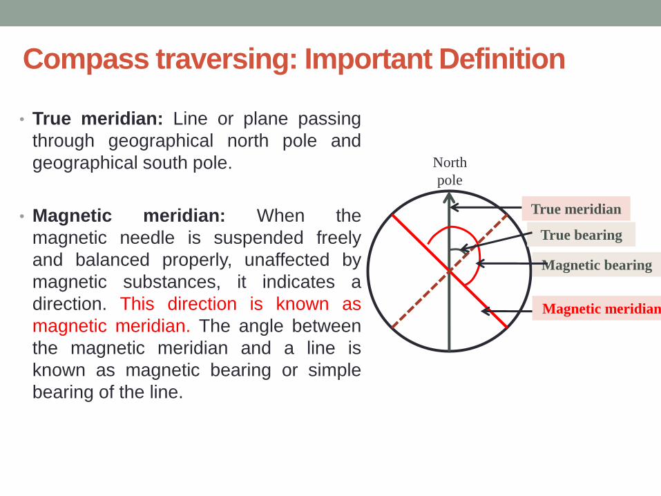
• True meridian: Line or plane passing
through geographical north pole and
geographical south pole.
• Magnetic meridian: When the
magnetic needle is suspended freely
and balanced properly, unaffected by
magnetic substances, it indicates a
direction. This direction is known as
magnetic meridian. The angle between
the magnetic meridian and a line is
known as magnetic bearing or simple
bearing of the line.
North
pole
True meridian
Magnetic meridian
True bearing
Magnetic bearing
• Magnetic declination: The horizontal angle between the magnetic meridian and true meridian is known as magnetic declination.
• Local Attraction
• Method of correction for traverse:
• First method: Sum of the interior angle should be equal to (2n-4) x 90. if not than distribute the total error equally to all interior angles of the traverse. Then starting from unaffected line the bearings of all the lines are corrected using corrected interior angles.
• Second method: Unaffected line is first detected. Then, commencing from the unaffected line, the bearing of other affected lines are corrected by finding the amount of correction at each station.
Compass traversing: Important Definition
Compass traversing: Important Definition
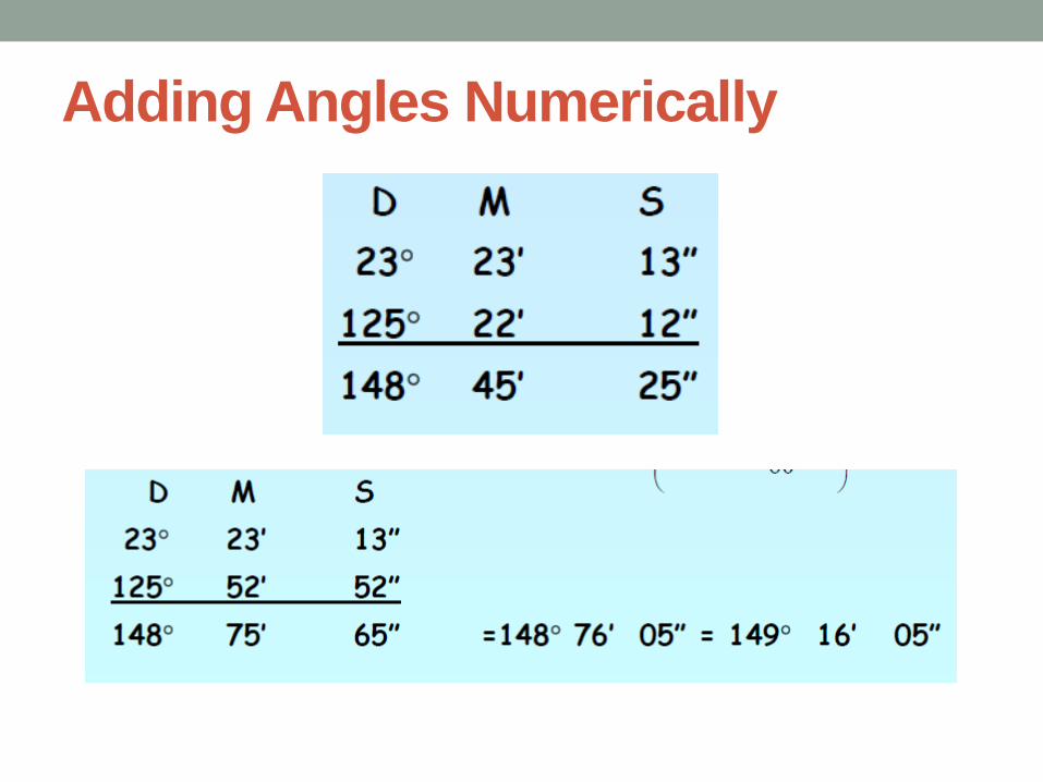
Adding Angles Numerically
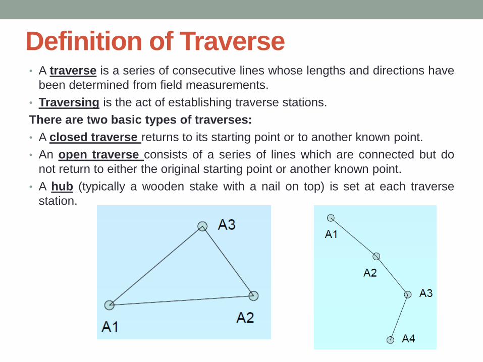
Definition of Traverse • A traverse is a series of consecutive lines whose lengths and directions have
been determined from field measurements.
• Traversing is the act of establishing traverse stations.
There are two basic types of traverses:
• A closed traverse returns to its starting point or to another known point.
• An open traverse consists of a series of lines which are connected but do
not return to either the original starting point or another known point.
• A hub (typically a wooden stake with a nail on top) is set at each traverse
station.

Principle of Compass Surveying • The principle of compass surveying is traversing, which involves a
series of connected lines. The magnetic bearings of the lines are measured by prismatic compass and the distances of the lines are measured by tape or chain. Such surveys does not require the formation of a network of triangles.
• Interior details are located by taking offsets from the main survey lines. Compass surveying is recommend when • A large area to be surveyed
• The course of a river or coast line is to be surveyed
• The area is crowded with many details and triangulation is not possible.
• Compass surveying is not recommended for areas where local attraction is suspected due to the presence of magnetic substances like steel structures, iron ore deposits, electric cables, etc.
Methods of Traversing
• Compass traversing: Fore bearings and back bearings between the
traverse leg are measured
• Theodolite traversing: Horizontal angles between the traverse legs
are measured. The length of the traverse legs are measured by
chain/tape or by stadia method
Checks on Traverse: Closed Traverse
• Check on closed traverse:
• Sum of the measured interior angles (2n-4) x 90°
• Sum of the measured exterior angles (2n+4) x 90 °
• The algebraic sum of the deflection angles should be equal to 360°.
• Right hand deflection is considered +ve, left hand deflection –ve
• Check on linear measurement
• The lines should be measured once each on two different days (along
opposite directions). Both measurement should tally.
• Linear measurement should also be taken by the stadia method. The
measurement by chaining and stadia method should tally.
Problems:
• Convert the following WCBs to QBs
• (a) WCB of AB = 45°30’
(Ans N 45°30’ E)
• (b) WCB of BC = 125°45’
(Ans 180- 125°45’ = S 54° 15’ E)
• Fore bearing of the following lines are given. Find back bearing
• AB=S 30°30’ E
• BC=N 40°30’ W
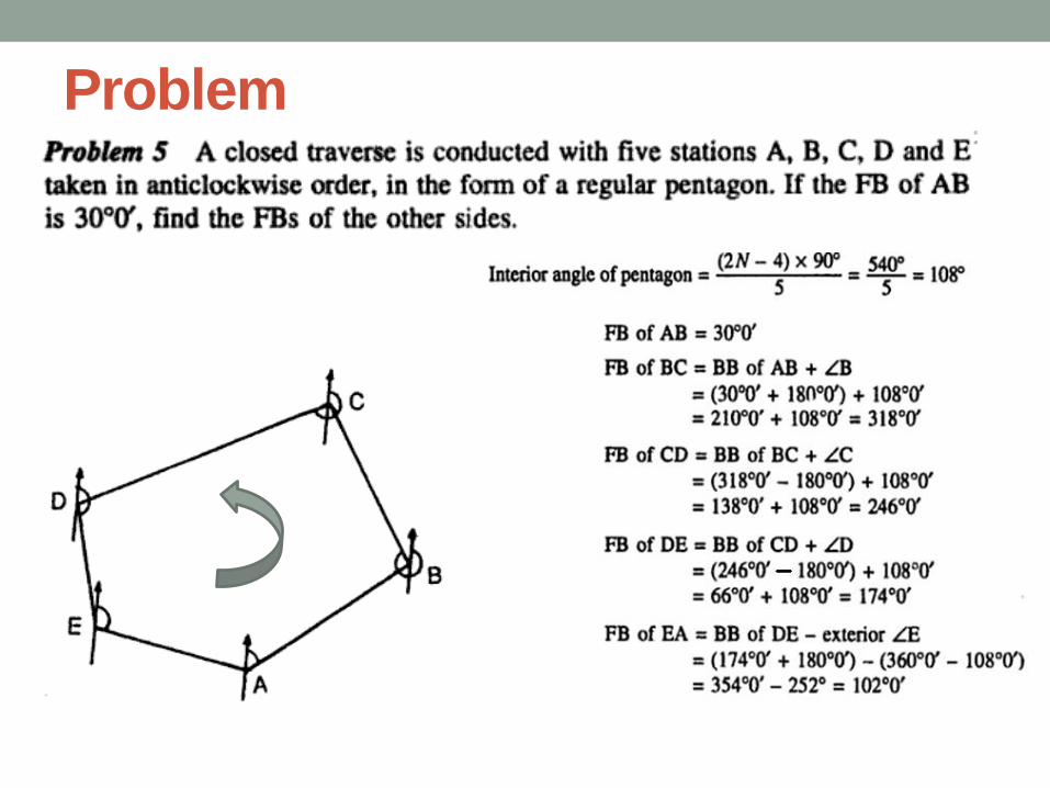
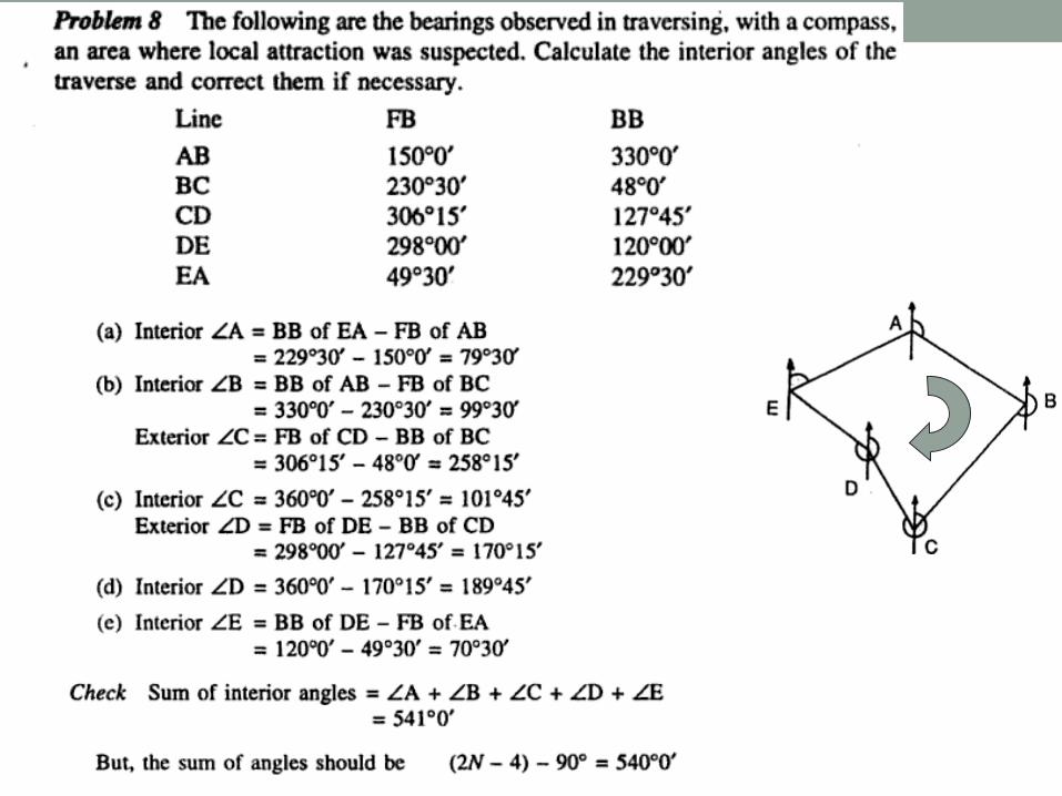
Problem
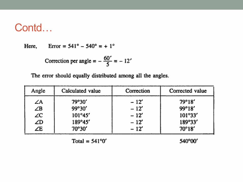
Contd…
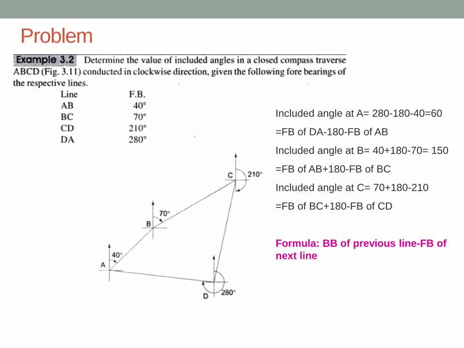
Problem
Included angle at A= 280-180-40=60
=FB of DA-180-FB of AB
Included angle at B= 40+180-70= 150
=FB of AB+180-FB of BC
Included angle at C= 70+180-210
=FB of BC+180-FB of CD
Formula: BB of previous line-FB of
next line
Problem
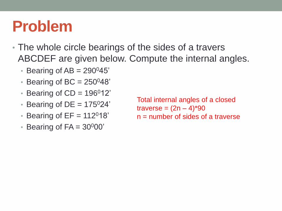
• The whole circle bearings of the sides of a travers
ABCDEF are given below. Compute the internal angles.
• Bearing of AB = 290045’
• Bearing of BC = 250048’
• Bearing of CD = 196012’
• Bearing of DE = 175024’
• Bearing of EF = 112018’
• Bearing of FA = 30000’
Total internal angles of a closed
traverse = (2n – 4)*90
n = number of sides of a traverse
Methods of Angel Measurement
Introduction
• Measurement of angles is basic to any survey operation
• When an angle is measured in a horizontal plane, it is
horizontal angle, when measured in vertical plane it is
vertical angle.
• Angle measurements involve three steps:
• Reference or starting point
• Direction of turning
• Angular value (value of the angle)
MEASUREMENT OF HORIZONTAL ANGLES
There are three methods of measuring horizontal
angles:-
i) Ordinary Method.
ii) Repetition Method.
iii) Reiteration Method.
MEASUREMENT OF HORIZONTAL ANGLES:
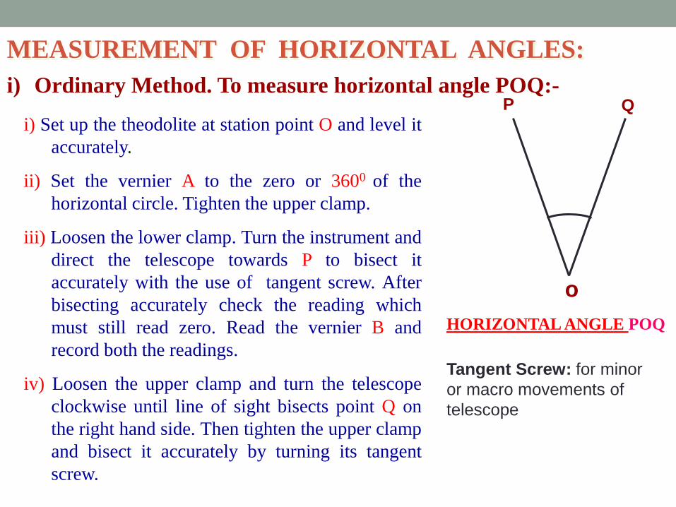
i) Ordinary Method. To measure horizontal angle POQ:-
i) Set up the theodolite at station point O and level it
accurately.
ii) Set the vernier A to the zero or 3600 of the
horizontal circle. Tighten the upper clamp.
iii) Loosen the lower clamp. Turn the instrument and
direct the telescope towards P to bisect it
accurately with the use of tangent screw. After
bisecting accurately check the reading which
must still read zero. Read the vernier B and
record both the readings.
iv) Loosen the upper clamp and turn the telescope
clockwise until line of sight bisects point Q on
the right hand side. Then tighten the upper clamp
and bisect it accurately by turning its tangent
screw.
o
P Q
HORIZONTAL ANGLE POQ
Tangent Screw: for minor
or macro movements of
telescope

i) Ordinary Method. To measure horizontal angle POQ :-
v) Read both verniers. The reading of the vernier a
which was initially set at zero gives the value of
the angle POQ directly and that of the other
vernier B by deducting 1800. The mean of the
two vernier readings gives the value of the
required angle POQ.
vi) Change the face of the instrument and repeat the
whole process. The mean of the two vernier
readings gives the second value of the angle
POQ which should be approximately or exactly
equal to the previous value.
vii) The mean of the two values of the angle POQ,
one with face left and the other with face right,
gives the required angle free from all
instrumental errors.
o
P Q
HORIZONTAL ANGLE POQ

i) Ordinary Method. To measure horizontal angle POQ:-
MEASUREMENT OF HORIZONTAL ANGLES
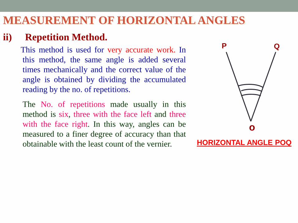
ii) Repetition Method. This method is used for very accurate work. In
this method, the same angle is added several
times mechanically and the correct value of the
angle is obtained by dividing the accumulated
reading by the no. of repetitions.
The No. of repetitions made usually in this
method is six, three with the face left and three
with the face right. In this way, angles can be
measured to a finer degree of accuracy than that
obtainable with the least count of the vernier.
o
P Q
HORIZONTAL ANGLE POQ
MEASUREMENT OF HORIZONTAL ANGLES
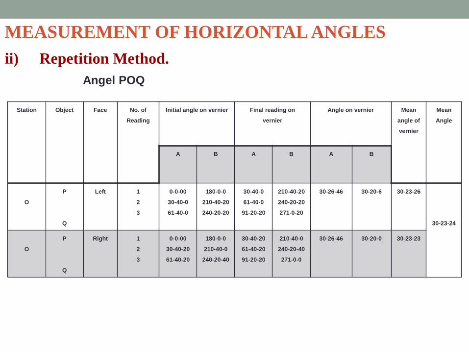
ii) Repetition Method.
Station Object Face No. of
Reading
Initial angle on vernier Final reading on
vernier
Angle on vernier Mean
angle of
vernier
Mean
Angle
A B A B A B
O
P
Q
Left 1
2
3
0-0-00
30-40-0
61-40-0
180-0-0
210-40-20
240-20-20
30-40-0
61-40-0
91-20-20
210-40-20
240-20-20
271-0-20
30-26-46 30-20-6 30-23-26
30-23-24
O
P
Q
Right 1
2
3
0-0-00
30-40-20
61-40-20
180-0-0
210-40-0
240-20-40
30-40-20
61-40-20
91-20-20
210-40-0
240-20-40
271-0-0
30-26-46 30-20-0 30-23-23
Angel POQ
ii) Repetition Method.
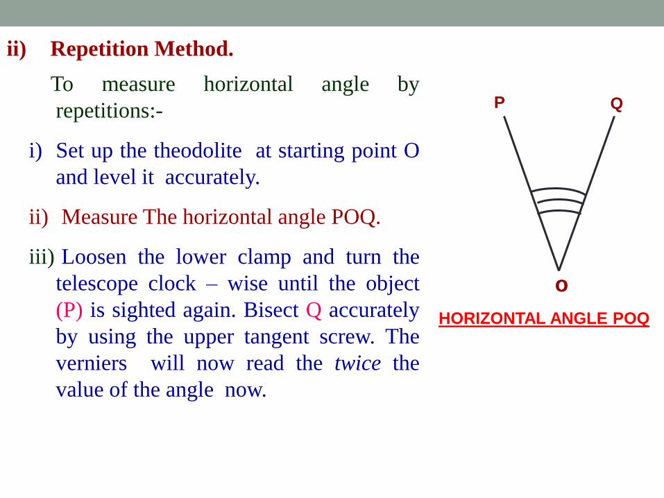
To measure horizontal angle by
repetitions:-
i) Set up the theodolite at starting point O
and level it accurately.
ii) Measure The horizontal angle POQ.
iii) Loosen the lower clamp and turn the
telescope clock – wise until the object
(P) is sighted again. Bisect Q accurately
by using the upper tangent screw. The
verniers will now read the twice the
value of the angle now.
o
P Q
HORIZONTAL ANGLE POQ
ii) Repetition Method contd...
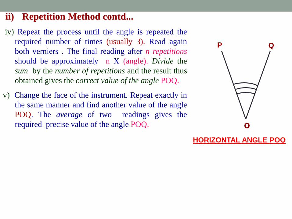
iv) Repeat the process until the angle is repeated the
required number of times (usually 3). Read again
both verniers . The final reading after n repetitions
should be approximately n X (angle). Divide the
sum by the number of repetitions and the result thus
obtained gives the correct value of the angle POQ.
v) Change the face of the instrument. Repeat exactly in
the same manner and find another value of the angle
POQ. The average of two readings gives the
required precise value of the angle POQ.
HORIZONTAL ANGLE POQ
o
P Q
MEASUREMENT OF HORIZONTAL ANGLES
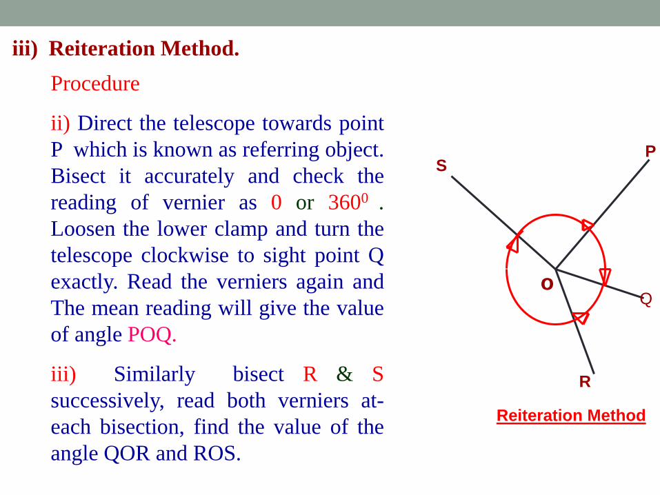
iii) Reiteration Method.
o
S P
Reiteration Method
R
Q
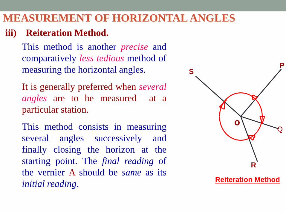
This method is another precise and
comparatively less tedious method of
measuring the horizontal angles.
It is generally preferred when several
angles are to be measured at a
particular station.
This method consists in measuring
several angles successively and
finally closing the horizon at the
starting point. The final reading of
the vernier A should be same as its
initial reading.
MEASUREMENT OF HORIZONTAL ANGLES:
iii) Reiteration Method.
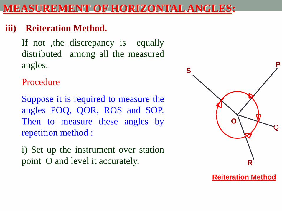
If not ,the discrepancy is equally
distributed among all the measured
angles.
Procedure
Suppose it is required to measure the
angles POQ, QOR, ROS and SOP.
Then to measure these angles by
repetition method :
i) Set up the instrument over station
point O and level it accurately.
o
S P
Reiteration Method
R
Q
iii) Reiteration Method.
Procedure
ii) Direct the telescope towards point
P which is known as referring object.
Bisect it accurately and check the
reading of vernier as 0 or 3600 .
Loosen the lower clamp and turn the
telescope clockwise to sight point Q
exactly. Read the verniers again and
The mean reading will give the value
of angle POQ.
iii) Similarly bisect R & S
successively, read both verniers at-
each bisection, find the value of the
angle QOR and ROS.
o
S P
Reiteration Method
R
Q
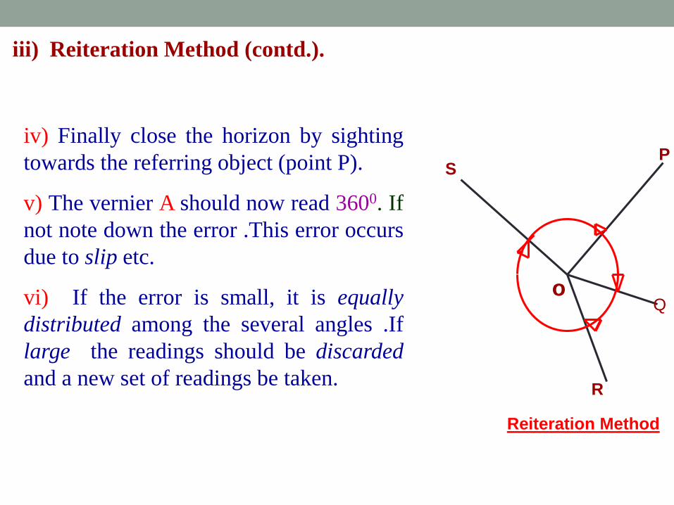
iii) Reiteration Method (contd.).
iv) Finally close the horizon by sighting
towards the referring object (point P).
v) The vernier A should now read 3600. If
not note down the error .This error occurs
due to slip etc.
vi) If the error is small, it is equally
distributed among the several angles .If
large the readings should be discarded
and a new set of readings be taken.
o
S P
Reiteration Method
R
Q
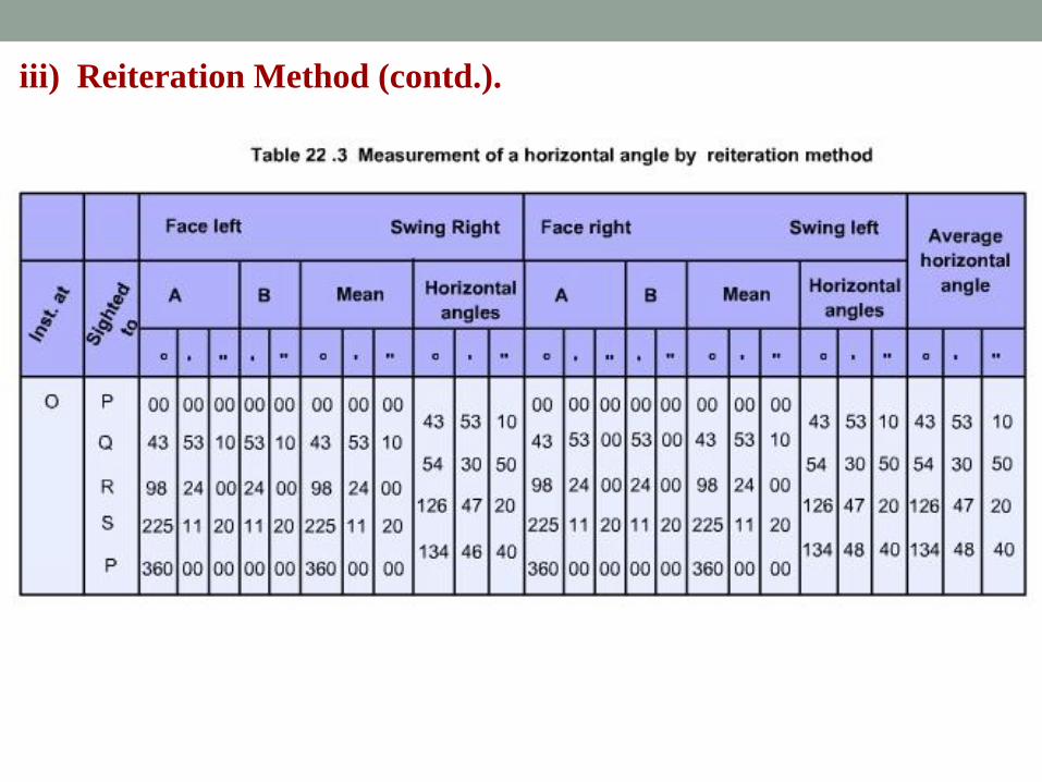
iii) Reiteration Method (contd.).
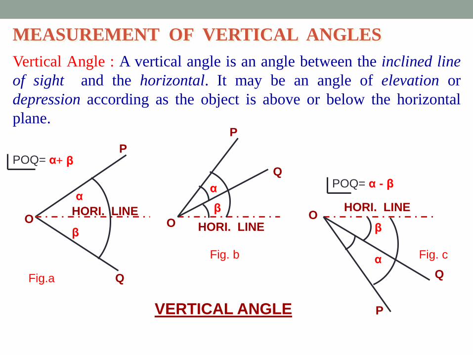
MEASUREMENT OF VERTICAL ANGLES
Vertical Angle : A vertical angle is an angle between the inclined line
of sight and the horizontal. It may be an angle of elevation or
depression according as the object is above or below the horizontal
plane.
P
Q
O O
P
Q
P
Q
O HORI. LINE
HORI. LINE
β
HORI. LINE
VERTICAL ANGLE
Fig.a
Fig. b Fig. c
POQ= α + β
POQ= α - β
β
β
α α
α
Traversing
(Balancing of a Traverse and Area Calculation)
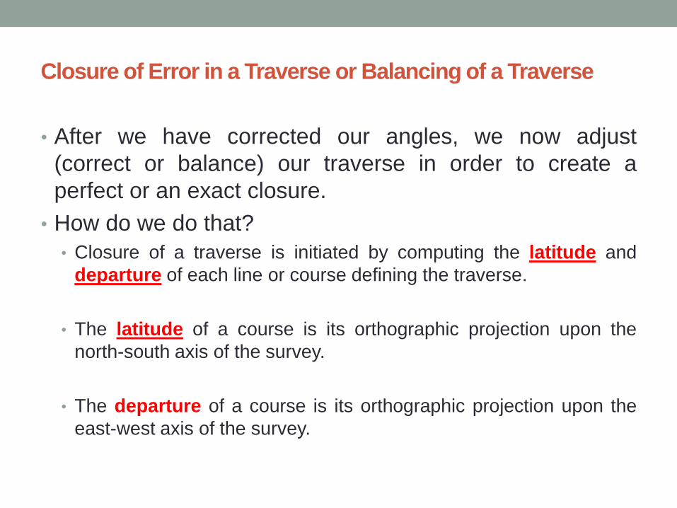
Closure of Error in a Traverse or Balancing of a Traverse
• After we have corrected our angles, we now adjust
(correct or balance) our traverse in order to create a
perfect or an exact closure.
• How do we do that?
• Closure of a traverse is initiated by computing the latitude and
departure of each line or course defining the traverse.
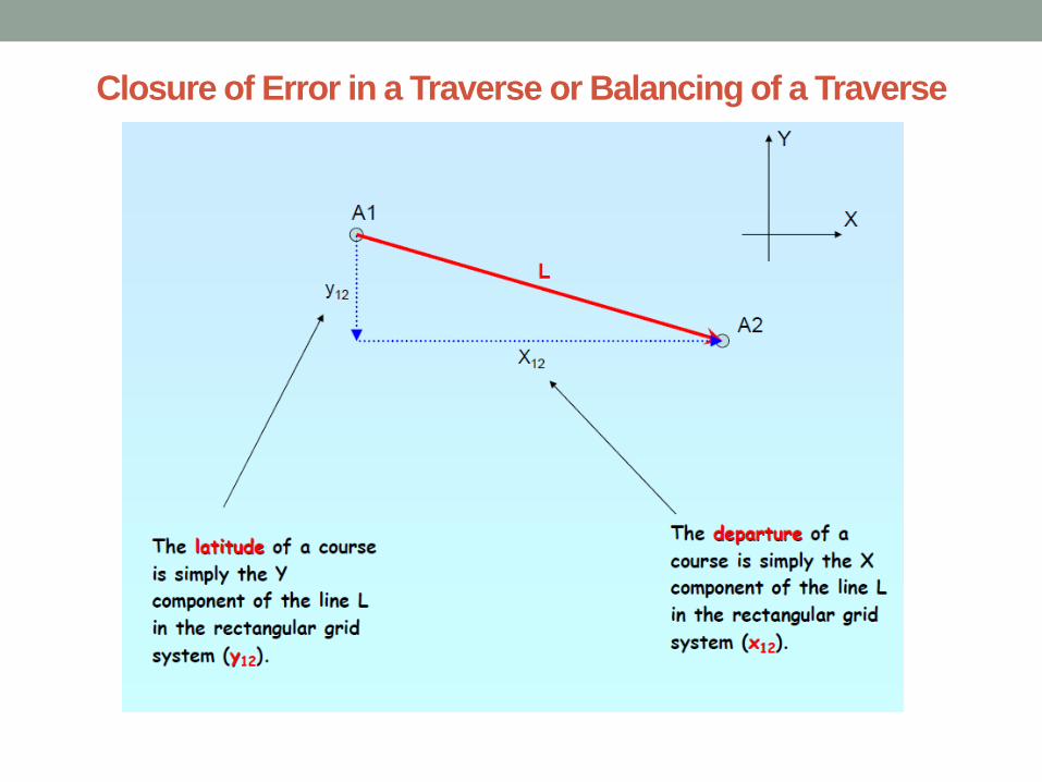
• The latitude of a course is its orthographic projection upon the
north-south axis of the survey.
• The departure of a course is its orthographic projection upon the
east-west axis of the survey.
Closure of Error in a Traverse or Balancing of a Traverse
Closure of Error in a Traverse or Balancing of a Traverse
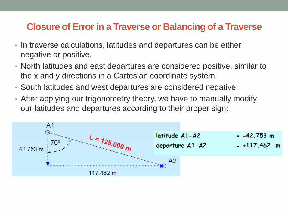
• In traverse calculations, latitudes and departures can be either
negative or positive.
• North latitudes and east departures are considered positive, similar to
the x and y directions in a Cartesian coordinate system.
• South latitudes and west departures are considered negative.
• After applying our trigonometry theory, we have to manually modify
our latitudes and departures according to their proper sign:
Closure of Error in a Traverse or Balancing of a Traverse
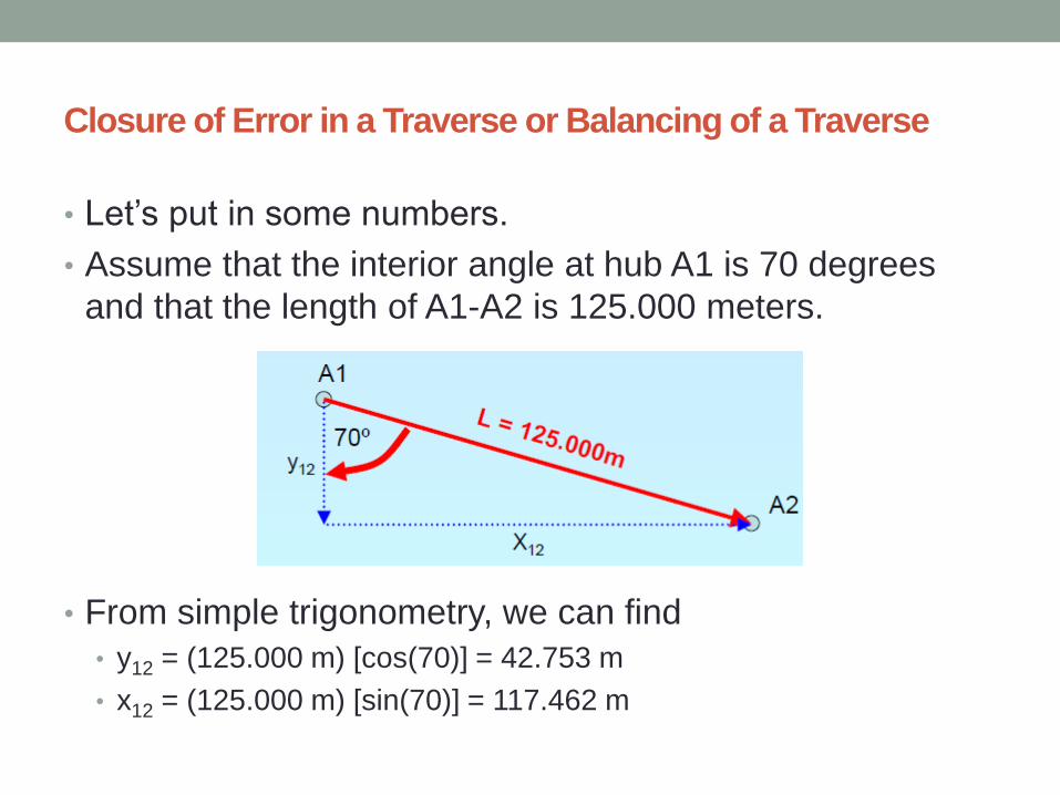
• Let’s put in some numbers.
• Assume that the interior angle at hub A1 is 70 degrees
and that the length of A1-A2 is 125.000 meters.
• From simple trigonometry, we can find
• y12 = (125.000 m) [cos(70)] = 42.753 m
• x12 = (125.000 m) [sin(70)] = 117.462 m
Closure of Error in a Traverse or Balancing of a Traverse
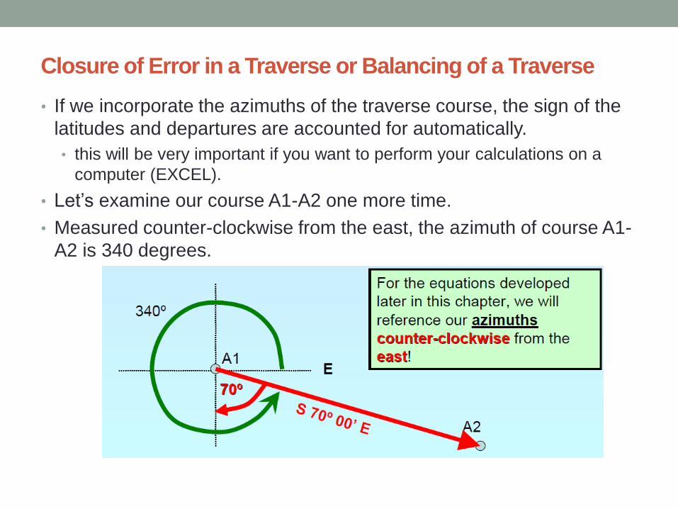
• If we incorporate the azimuths of the traverse course, the sign of the
latitudes and departures are accounted for automatically.
• this will be very important if you want to perform your calculations on a
computer (EXCEL).
• Let’s examine our course A1-A2 one more time.
• Measured counter-clockwise from the east, the azimuth of course A1-
A2 is 340 degrees.
Closure of Error in a Traverse or Balancing of a Traverse
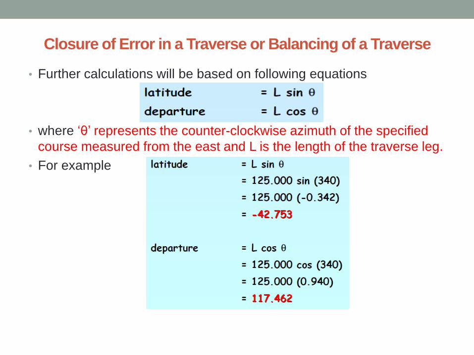
• Further calculations will be based on following equations
• where ‘θ’ represents the counter-clockwise azimuth of the specified
course measured from the east and L is the length of the traverse leg.
• For example
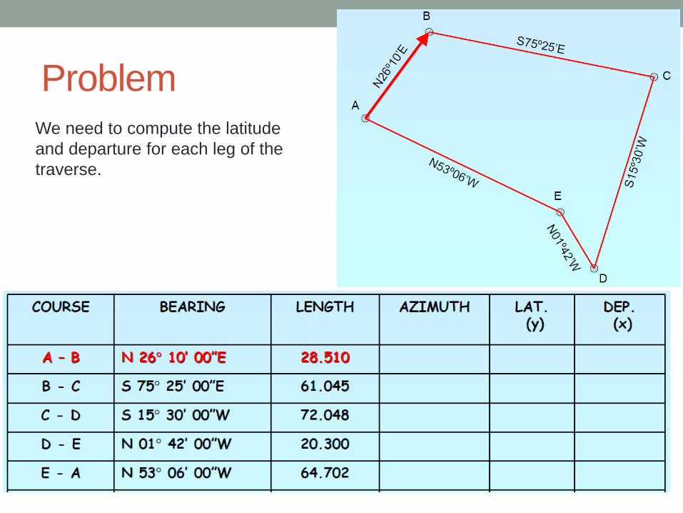
Problem We need to compute the latitude
and departure for each leg of the
traverse.
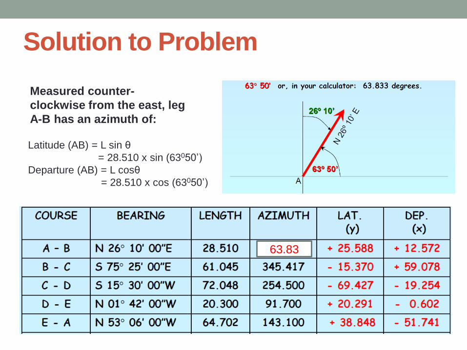
Solution to Problem
Measured counter-
clockwise from the east, leg
A-B has an azimuth of:
Latitude (AB) = L sin θ
= 28.510 x sin (63050’)
Departure (AB) = L cosθ
= 28.510 x cos (63050’)
63.83
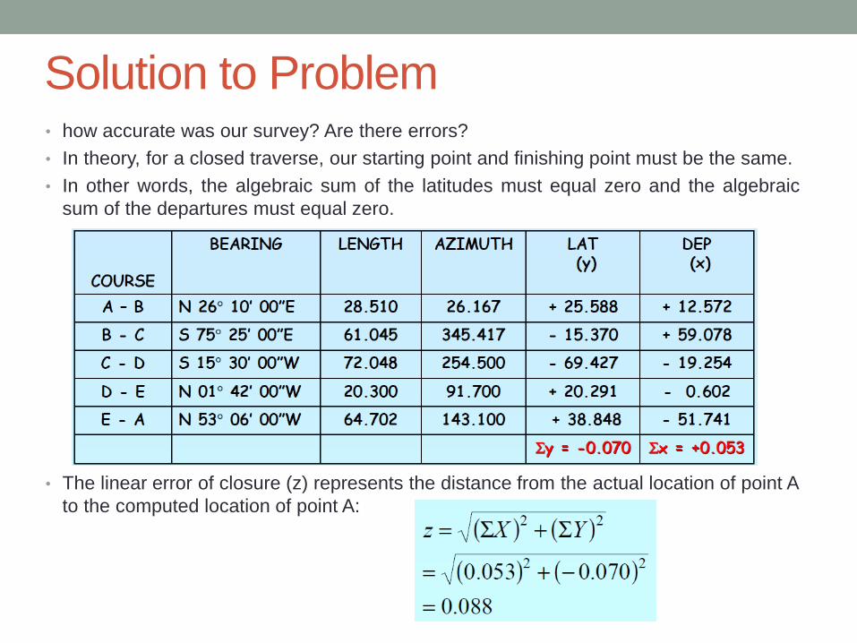
Solution to Problem • how accurate was our survey? Are there errors?
• In theory, for a closed traverse, our starting point and finishing point must be the same.
• In other words, the algebraic sum of the latitudes must equal zero and the algebraic
sum of the departures must equal zero.
• The linear error of closure (z) represents the distance from the actual location of point A
to the computed location of point A:
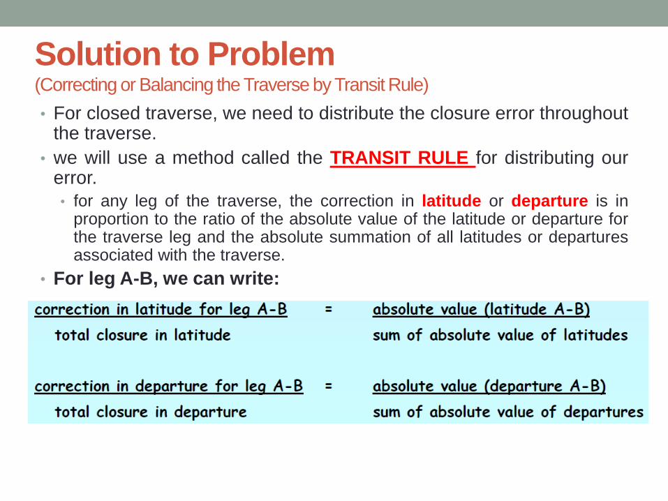
Solution to Problem (Correcting or Balancing the Traverse by Transit Rule)
• For closed traverse, we need to distribute the closure error throughout the traverse.
• we will use a method called the TRANSIT RULE for distributing our error.
• for any leg of the traverse, the correction in latitude or departure is in proportion to the ratio of the absolute value of the latitude or departure for the traverse leg and the absolute summation of all latitudes or departures associated with the traverse.
• For leg A-B, we can write:

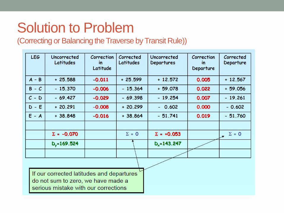
Solution to Problem (Correcting or Balancing the Traverse by Transit Rule))
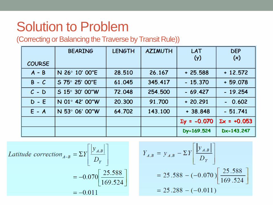
Solution to Problem (Correcting or Balancing the Traverse by Transit Rule))
Solution to Problem (Correcting or Balancing the Traverse by Transit Rule))
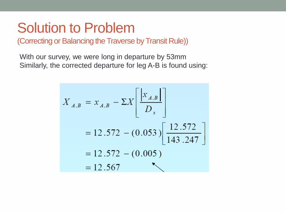
With our survey, we were long in departure by 53mm
Similarly, the corrected departure for leg A-B is found using:
Solution to Problem (Correcting or Balancing the Traverse by Transit Rule))
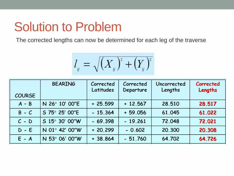
Solution to Problem The corrected lengths can now be determined for each leg of the traverse
Example
Latitude (L*Cosθ) Departure (L*Sinθ)
Line Length (L) WCB from North Q.B. (θ) Northing (+) Southing (-) Easting (+) Westing (-)
AB
BC
CD
DE
102.5
108.7
92.5
125.0
261041’
9006’
282022’
71030’
S 81041’ W
N 9006’ E
N 77038’ W
N 71030’ E
107.331
19.815
39.663
14.796
17.190
118.54
101.426
90.352
Σ 166.809 14.796 135.730 191.778
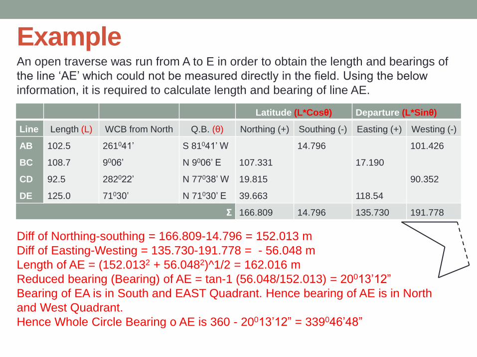
Diff of Northing-southing = 166.809-14.796 = 152.013 m
Diff of Easting-Westing = 135.730-191.778 = - 56.048 m
Length of AE = (152.0132 + 56.0482)^1/2 = 162.016 m
Reduced bearing (Bearing) of AE = tan-1 (56.048/152.013) = 20013’12”
Bearing of EA is in South and EAST Quadrant. Hence bearing of AE is in North
and West Quadrant.
Hence Whole Circle Bearing o AE is 360 - 20013’12” = 339046’48”
An open traverse was run from A to E in order to obtain the length and bearings of
the line ‘AE’ which could not be measured directly in the field. Using the below
information, it is required to calculate length and bearing of line AE.
Example
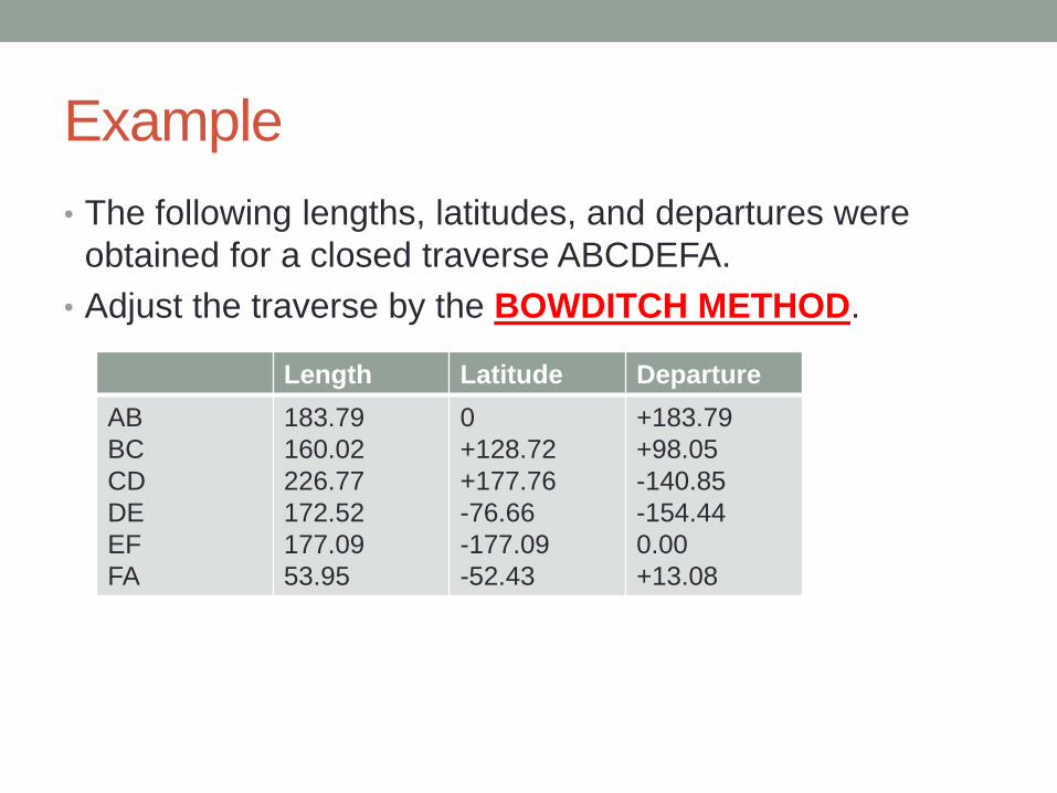
• The following lengths, latitudes, and departures were
obtained for a closed traverse ABCDEFA.
• Adjust the traverse by the BOWDITCH METHOD.
Length Latitude Departure
AB
BC
CD
DE
EF
FA
183.79
160.02
226.77
172.52
177.09
53.95
0
+128.72
+177.76
-76.66
-177.09
-52.43
+183.79
+98.05
-140.85
-154.44
0.00
+13.08
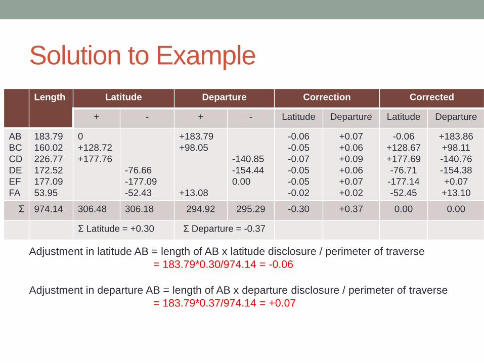
Solution to Example
Length Latitude Departure Correction Corrected
+ - + - Latitude Departure Latitude Departure
AB
BC
CD
DE
EF
FA
183.79
160.02
226.77
172.52
177.09
53.95
0
+128.72
+177.76
-76.66
-177.09
-52.43
+183.79
+98.05
+13.08
-140.85
-154.44
0.00
-0.06
-0.05
-0.07
-0.05
-0.05
-0.02
+0.07
+0.06
+0.09
+0.06
+0.07
+0.02
-0.06
+128.67
+177.69
-76.71
-177.14
-52.45
+183.86
+98.11
-140.76
-154.38
+0.07
+13.10
Σ 974.14 306.48 306.18 294.92 295.29 -0.30 +0.37 0.00 0.00
Σ Latitude = +0.30 Σ Departure = -0.37
Adjustment in latitude AB = length of AB x latitude disclosure / perimeter of traverse
= 183.79*0.30/974.14 = -0.06
Adjustment in departure AB = length of AB x departure disclosure / perimeter of traverse
= 183.79*0.37/974.14 = +0.07
Methods of Traverse Area Calculation
• Calculation of Traverse Area
• The area of a closed traverse may be calculated from:
• The coordinates (x and y)
• The latitude and double meridian distance
• The departure and total latitudes
61
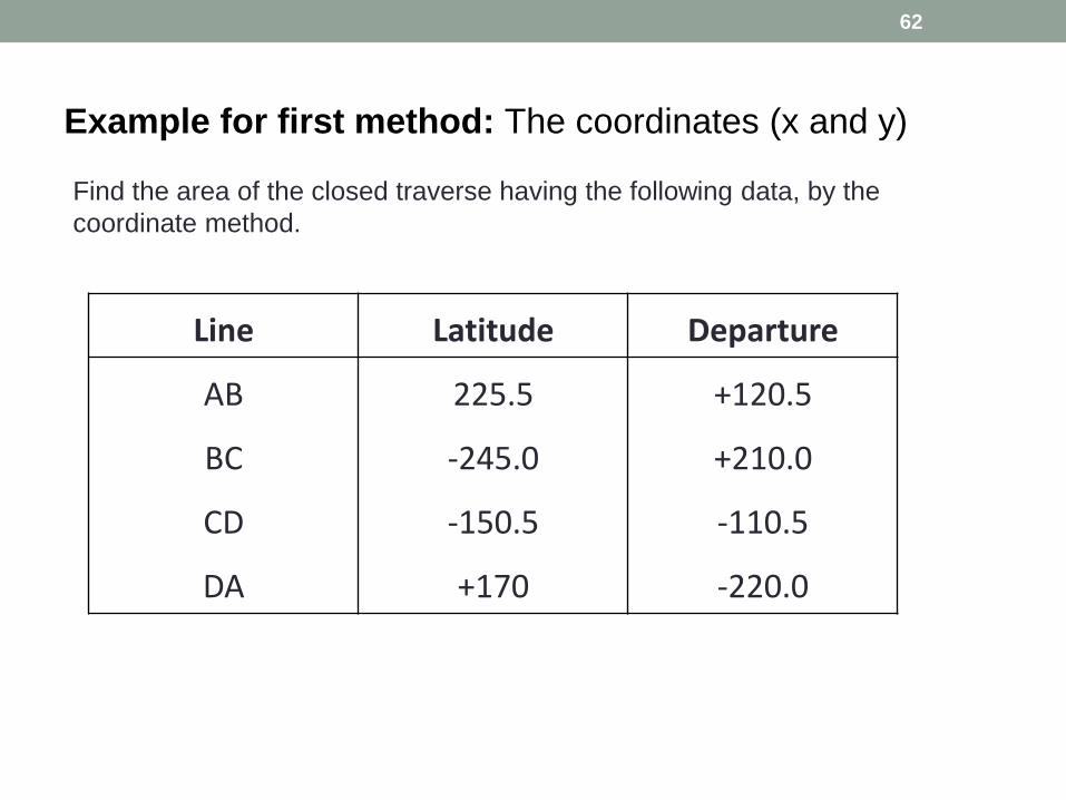
Example for first method: The coordinates (x and y)
62
Find the area of the closed traverse having the following data, by the
coordinate method.
Line Latitude Departure
AB
BC
CD
DA
225.5
-245.0
-150.5
+170
+120.5
+210.0
-110.5
-220.0
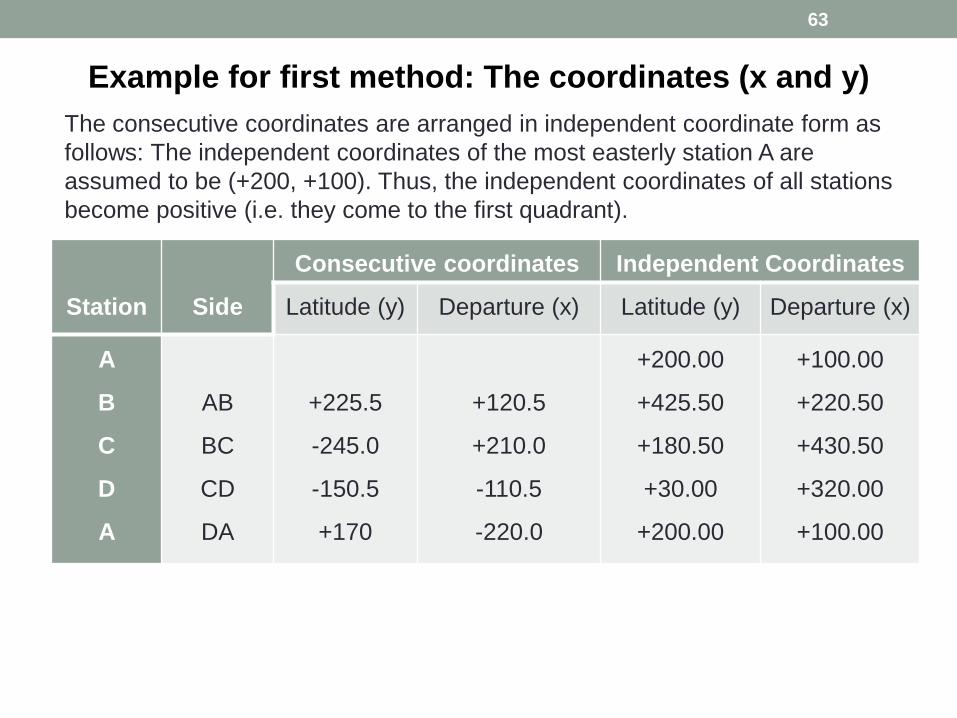
Example for first method: The coordinates (x and y)
63
The consecutive coordinates are arranged in independent coordinate form as
follows: The independent coordinates of the most easterly station A are
assumed to be (+200, +100). Thus, the independent coordinates of all stations
become positive (i.e. they come to the first quadrant).
Station
Side
Consecutive coordinates Independent Coordinates
Latitude (y) Departure (x) Latitude (y) Departure (x)
A
B
C
D
A
AB
BC
CD
DA
+225.5
-245.0
-150.5
+170
+120.5
+210.0
-110.5
-220.0
+200.00
+425.50
+180.50
+30.00
+200.00
+100.00
+220.50
+430.50
+320.00
+100.00
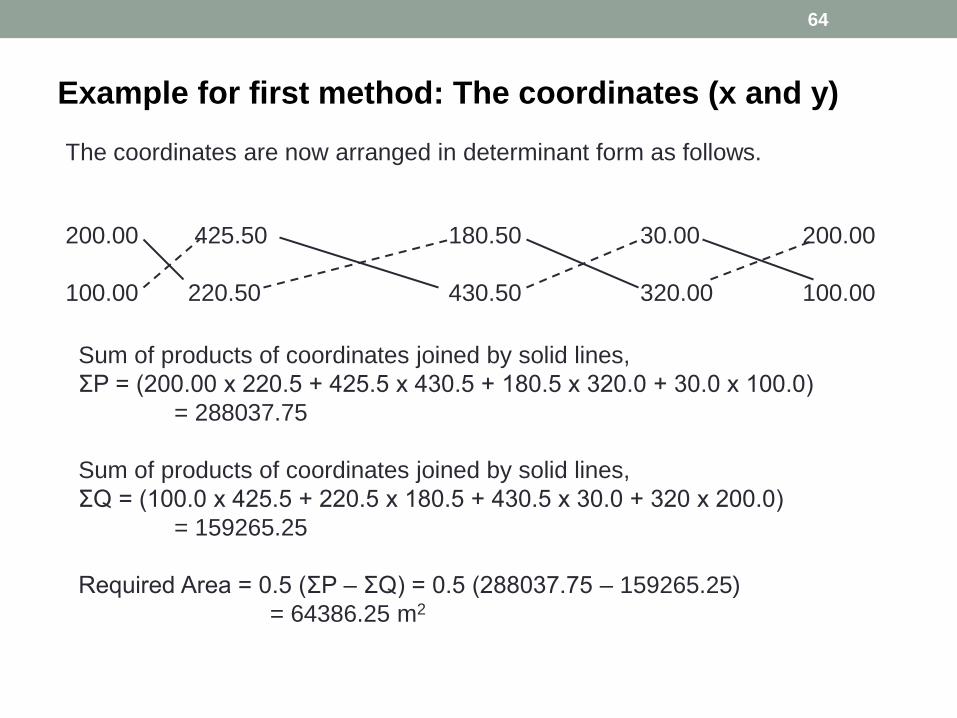
Example for first method: The coordinates (x and y)
64
The coordinates are now arranged in determinant form as follows.
200.00 425.50 180.50 30.00 200.00
100.00 220.50 430.50 320.00 100.00
Sum of products of coordinates joined by solid lines,
ΣP = (200.00 x 220.5 + 425.5 x 430.5 + 180.5 x 320.0 + 30.0 x 100.0)
= 288037.75
Sum of products of coordinates joined by solid lines,
ΣQ = (100.0 x 425.5 + 220.5 x 180.5 + 430.5 x 30.0 + 320 x 200.0)
= 159265.25
Required Area = 0.5 (ΣP – ΣQ) = 0.5 (288037.75 – 159265.25)
= 64386.25 m2
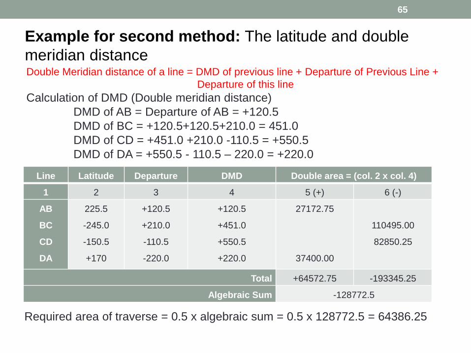
Example for second method: The latitude and double
meridian distance
65
Double Meridian distance of a line = DMD of previous line + Departure of Previous Line +
Departure of this line
Calculation of DMD (Double meridian distance)
DMD of AB = Departure of AB = +120.5
DMD of BC = +120.5+120.5+210.0 = 451.0
DMD of CD = +451.0 +210.0 -110.5 = +550.5
DMD of DA = +550.5 - 110.5 – 220.0 = +220.0
Line Latitude Departure DMD Double area = (col. 2 x col. 4)
1 2 3 4 5 (+) 6 (-)
AB
BC
CD
DA
225.5
-245.0
-150.5
+170
+120.5
+210.0
-110.5
-220.0
+120.5
+451.0
+550.5
+220.0
27172.75
37400.00
110495.00
82850.25
Total +64572.75 -193345.25
Algebraic Sum -128772.5
Required area of traverse = 0.5 x algebraic sum = 0.5 x 128772.5 = 64386.25
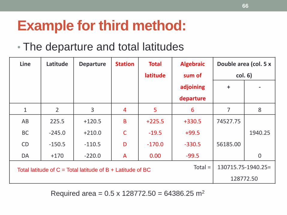
Example for third method:
• The departure and total latitudes
66
Line Latitude Departure Station Total
latitude
Algebraic
sum of
adjoining
departure
Double area (col. 5 x
col. 6)
+ -
1 2 3 4 5 6 7 8
AB
BC
CD
DA
225.5
-245.0
-150.5
+170
+120.5
+210.0
-110.5
-220.0
B
C
D
A
+225.5
-19.5
-170.0
0.00
+330.5
+99.5
-330.5
-99.5
74527.75
56185.00
1940.25
0
Total = 130715.75-1940.25=
128772.50
Required area = 0.5 x 128772.50 = 64386.25 m2
Total latitude of C = Total latitude of B + Latitude of BC