gps navigator gp-33 - busse yachtshop · i important notice general • this manual has been...
TRANSCRIPT

The paper used in this manualis elemental chlorine free.
・FURUNO Authorized Distributor/Dealer
9-52 Ashihara-cho,Nishinomiya, 662-8580, JAPAN
Telephone : +81-(0)798-65-2111Fax : +81-(0)798-65-4200
A : JAN 2010.Printed in JapanAll rights reserved.
Pub. No. OME-44580-A
*00017317710**00017317710*(HIMA ) GP-33*00017317710**00017317710** 0 0 0 1 7 3 1 7 7 1 0 *
www.busse-yachtshop.de | [email protected]
i
IMPORTANT NOTICE
General• This manual has been authored with simplified grammar, to meet the needs of international us-
ers.• The operator of this equipment must read and follow the descriptions in this manual. Wrong op-
eration or maintenance can cancel the warranty or cause injury.• Do not copy any part of this manual without written permission from FURUNO.• If this manual is lost or worn, contact your dealer about replacement.• The contents of this manual and equipment specifications can change without notice.• The example screens (or illustrations) shown in this manual can be different from the screens
you see on your display. The screens you see depend on your system configuration and equip-ment settings.
• Save this manual for future reference.• Any modification of the equipment (including software) by persons not authorized by FURUNO
will cancel the warranty.• All brand and product names are trademarks, registered trademarks or service marks of their
respective holders.
How to discard this productDiscard this product according to local regulations for the disposal of industrial waste. For disposal in the USA, see the homepage of the Electronics Industries Alliance (http://www.eiae.org/) for the correct method of disposal.
How to discard a used batterySome FURUNO products have a battery(ies). To see if your product has a battery(ies), see the chapter on Maintenance. Follow the instructions below if a battery(ies) is used.
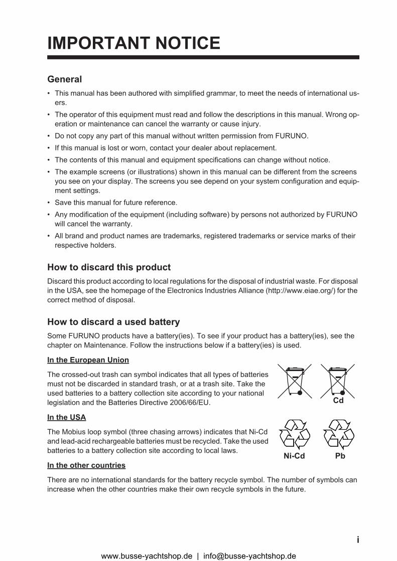
In the European Union
The crossed-out trash can symbol indicates that all types of batteries must not be discarded in standard trash, or at a trash site. Take the used batteries to a battery collection site according to your national legislation and the Batteries Directive 2006/66/EU.
In the USA
The Mobius loop symbol (three chasing arrows) indicates that Ni-Cd and lead-acid rechargeable batteries must be recycled. Take the used batteries to a battery collection site according to local laws.
In the other countries
There are no international standards for the battery recycle symbol. The number of symbols can increase when the other countries make their own recycle symbols in the future.
Cd
Ni-Cd Pb
www.busse-yachtshop.de | [email protected]
ii
SAFETY INSTRUCTIONS
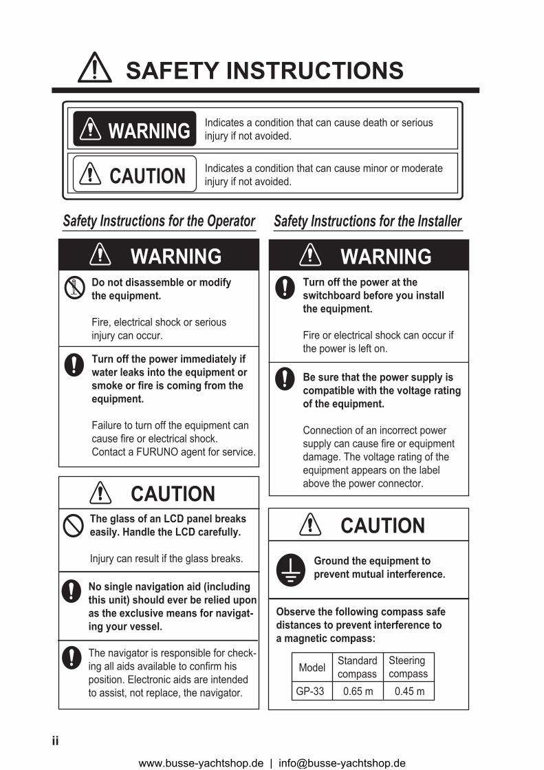
WARNINGDo not disassemble or modifythe equipment.
Fire, electrical shock or seriousinjury can occur.
WARNING Indicates a condition that can cause death or serious injury if not avoided.
CAUTION Indicates a condition that can cause minor or moderate injury if not avoided.
Safety Instructions for the Operator Safety Instructions for the Installer
Be sure that the power supply iscompatible with the voltage ratingof the equipment.
Connection of an incorrect powersupply can cause fire or equipmentdamage. The voltage rating of theequipment appears on the labelabove the power connector.
Turn off the power immediately ifwater leaks into the equipment orsmoke or fire is coming from theequipment.
Failure to turn off the equipment cancause fire or electrical shock.Contact a FURUNO agent for service.
CAUTIONThe glass of an LCD panel breakseasily. Handle the LCD carefully.
Injury can result if the glass breaks.
WARNING
CAUTION
Turn off the power at theswitchboard before you installthe equipment.
Fire or electrical shock can occur ifthe power is left on.
Ground the equipment toprevent mutual interference.
Observe the following compass safedistances to prevent interference toa magnetic compass:
GP-33
Standardcompass
Steeringcompass
0.65 m 0.45 m
Model
No single navigation aid (includingthis unit) should ever be relied upon as the exclusive means for navigat-ing your vessel.
The navigator is responsible for check-ing all aids available to confirm his position. Electronic aids are intended to assist, not replace, the navigator.
www.busse-yachtshop.de | [email protected]

iii
TABLE OF CONTENTSFOREWORD.................................................................................................................... vSYSTEM CONFIGURATION .......................................................................................... vi
1. OPERATIONAL OVERVIEW.................................................................................1-11.1 Controls ......................................................................................................................1-11.2 How to Turn Power On/Off .........................................................................................1-21.3 How to Adjust LCD and Key Panel Brilliance .............................................................1-31.4 Display Modes............................................................................................................1-31.5 Menu Overview...........................................................................................................1-81.6 How to Enter the MOB Mark.......................................................................................1-9
2. PLOTTER DISPLAY OVERVIEW..........................................................................2-12.1 How to Select the Display Range...............................................................................2-12.2 How to Shift the Cursor ..............................................................................................2-12.3 How to Shift the Display .............................................................................................2-22.4 How to Change Track Plotting Interval, Stop Recording ............................................2-32.5 How to Change Track Color .......................................................................................2-42.6 How to Erase Track ....................................................................................................2-4
2.6.1 How to erase track by color ............................................................................2-42.6.2 How to erase all tracks ...................................................................................2-5
3. WAYPOINTS..........................................................................................................3-13.1 How to Enter Waypoints .............................................................................................3-1
3.1.1 How to enter a waypoint with the cursor ........................................................3-13.1.2 How to enter a waypoint at own boat position................................................3-13.1.3 How to enter a waypoint through the list ........................................................3-13.1.4 How to enter waypoints automatically ............................................................3-3
3.2 How to Display Waypoint Name.................................................................................3-43.3 How to Edit Waypoints ...............................................................................................3-5
3.3.1 How to edit waypoints on the plotter display ..................................................3-53.3.2 How to edit waypoints through the list ............................................................3-5
3.4 How to Move Waypoints.............................................................................................3-63.5 How to Erase Waypoints ............................................................................................3-7
3.5.1 How to erase a waypoint on the plotter display..............................................3-73.5.2 How to erase a waypoint through the waypoint list ........................................3-73.5.3 How to erase all waypoints.............................................................................3-8
4. ROUTES ................................................................................................................4-14.1 How to Create Routes ................................................................................................4-14.2 How to Edit Routes.....................................................................................................4-3
4.2.1 How to replace a waypoint in a route .............................................................4-34.2.2 How to delete a waypoint from a route...........................................................4-34.2.3 How to insert a waypoint in a route ................................................................4-44.2.4 How to temporarily deselect a waypoint in a route.........................................4-4
4.3 How to Erase a Route ................................................................................................4-54.3.1 How to erase a route through the route list ....................................................4-54.3.2 How to erase all routes...................................................................................4-5
5. DESTINATION .......................................................................................................5-15.1 How to Set Destination by Cursor Position.................................................................5-15.2 How to Set Destination by Waypoint ..........................................................................5-2
5.2.1 How to set a destination waypoint with the cursor .........................................5-2
www.busse-yachtshop.de | [email protected]

TABLE OF CONTENTS
iv
5.2.2 How to set a destination waypoint through the list ......................................... 5-25.3 How to Set Route as Destination ............................................................................... 5-25.4 How to Cancel Destination......................................................................................... 5-3
5.4.1 How to cancel destination with the cursor...................................................... 5-35.4.2 How to cancel destination through the list...................................................... 5-4
6. ALARMS ................................................................................................................6-16.1 Overview .................................................................................................................... 6-16.2 Buzzer Type Selection ............................................................................................... 6-26.3 How to Set an Alarm .................................................................................................. 6-26.4 Alarm Descriptions ..................................................................................................... 6-4
7. OTHER FUNCTIONS .............................................................................................7-17.1 Plotter Setup Menu .................................................................................................... 7-17.2 GPS Setup Menu ....................................................................................................... 7-27.3 WAAS Menu............................................................................................................... 7-47.4 Position Display Format ............................................................................................. 7-47.5 System Menu ............................................................................................................. 7-57.6 User Display Menu..................................................................................................... 7-77.7 I/O Setup Menu ........................................................................................................ 7-10
7.7.1 Uploading data to a PC................................................................................ 7-137.7.2 Downloading data from PC .......................................................................... 7-13
8. MAINTENANCE, TROUBLESHOOTING...............................................................8-18.1 Maintenance............................................................................................................... 8-18.2 Troubleshooting ......................................................................................................... 8-28.3 Displaying the Message Board .................................................................................. 8-38.4 Diagnostics................................................................................................................. 8-38.5 Clearing Data ............................................................................................................. 8-4
9. INSTALLATION .....................................................................................................9-19.1 Equipment Lists.......................................................................................................... 9-19.2 Installation of Receiver Unit ....................................................................................... 9-1
9.2.1 Installation consideration................................................................................ 9-19.2.2 Desktop and underside of table mount .......................................................... 9-29.2.3 Flush mount ................................................................................................... 9-3
9.3 Installation of Antenna Unit ........................................................................................ 9-49.3.1 Installation consideration................................................................................ 9-4
9.4 Wiring ......................................................................................................................... 9-59.5 Language Setting ....................................................................................................... 9-89.6 Input/Output Data....................................................................................................... 9-8
APPENDIX 1 MENU TREE .......................................................................................AP-1APPENDIX 2 WHAT IS WAAS? ...............................................................................AP-3APPENDIX 3 LIST OF TERMS .................................................................................AP-4SPECIFICATIONS .....................................................................................................SP-1OUTLINE DRAWINGS.................................................................................................D-1INTERCONNECTION DIAKGRAM.............................................................................. S-1INDEX.......................................................................................................................... IN-1
www.busse-yachtshop.de | [email protected]
v
FOREWORD
A Word to the Owner of the GP-33Congratulations on your choice of the GP-33 GPS Navigator.
For over 60 years FURUNO Electric Company has enjoyed an enviable reputation for innovative and dependable marine electronics is furthered by our extensive global network of agents and dealers.
Your navigator is designed and constructed to meet the rigorous demands of the marine environ-ment. However, no machine can perform its intended function unless installed, operated and maintained properly. Please carefully read and follow the recommended procedures for installa-tion, operation and maintenance.
We would appreciate feedback from you, the end-user, about where we are achieving ourpurposes.
Thank you for considering and purchasing FURUNO equipment.
FeaturesThe main features of the GP-33 are as shown below.
• High-resolution color LCD• WAAS capability• Storage for 10,000 waypoints, 100 routes and 3,000 track points• Alarms: Arrival/Anchor, XTE (Cross-track Error), Trip, Odometer, Time, WAAS and Speed• Man overboard feature records position at time of man overboard and provides continuous up-
dates of range and bearing when navigating to the MOB position.• Unique Highway display provides a graphic presentation of boat’s progress toward a waypoint.• User-programmable nav data displays provide analog and digital navigation data.• Navigation data output to the autopilot when connecting.• Waypoint and route data can be uploaded from a PC and downloaded to a PC.
Program No.
**: Minor change
Name No. Ver.
CPU MAIN 2051530-01.** January, 2010
CPU Boot 2051531-01.** January, 2010
CPU CAN LD 2051532-01.** January, 2010
GPS 48502640-** January, 2010
www.busse-yachtshop.de | [email protected]
vi
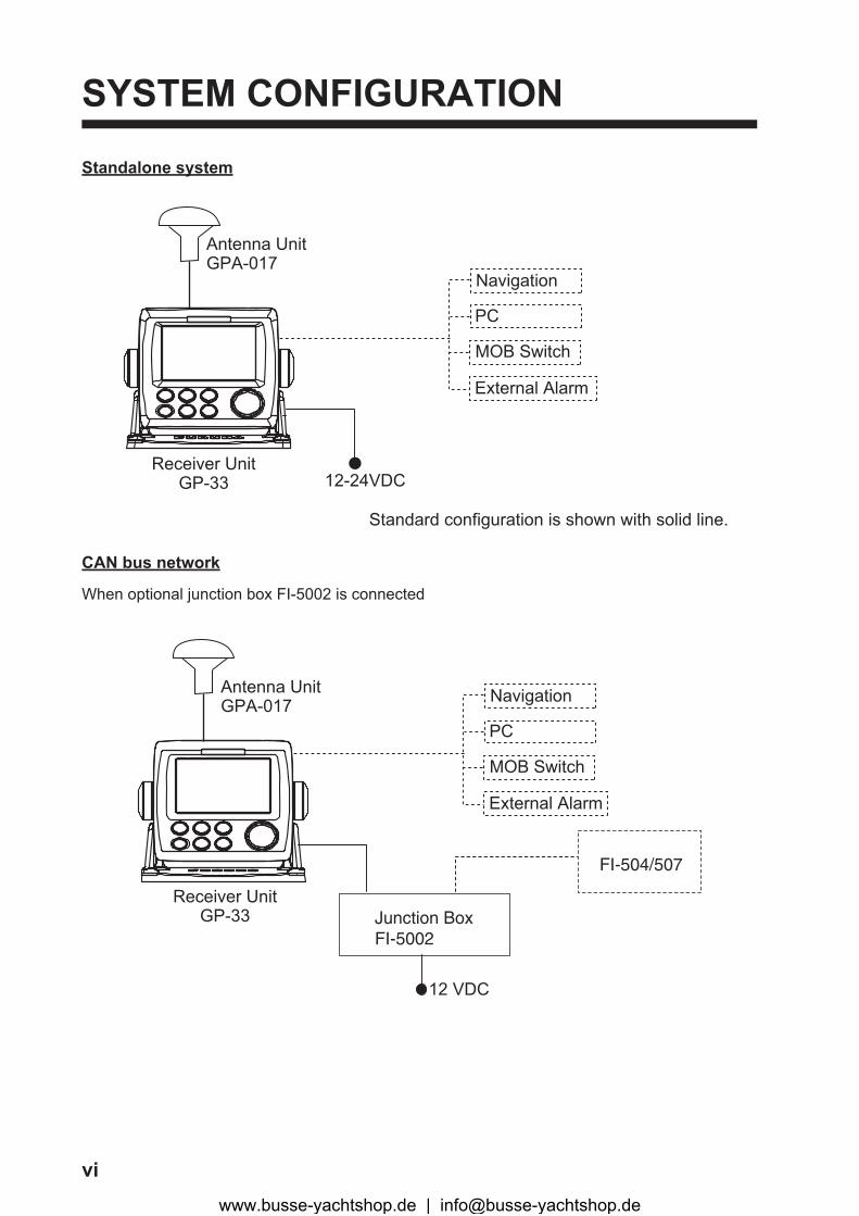
SYSTEM CONFIGURATION
Standalone system
CAN bus network
When optional junction box FI-5002 is connected
Navigation
Receiver UnitGP-33
Antenna UnitGPA-017
PC
12-24VDC
MOB Switch
External Alarm
Standard configuration is shown with solid line.
Receiver UnitGP-33
Antenna UnitGPA-017
FI-504/507
12 VDC
Junction BoxFI-5002
Navigation
PC
MOB Switch
External Alarm
www.busse-yachtshop.de | [email protected]
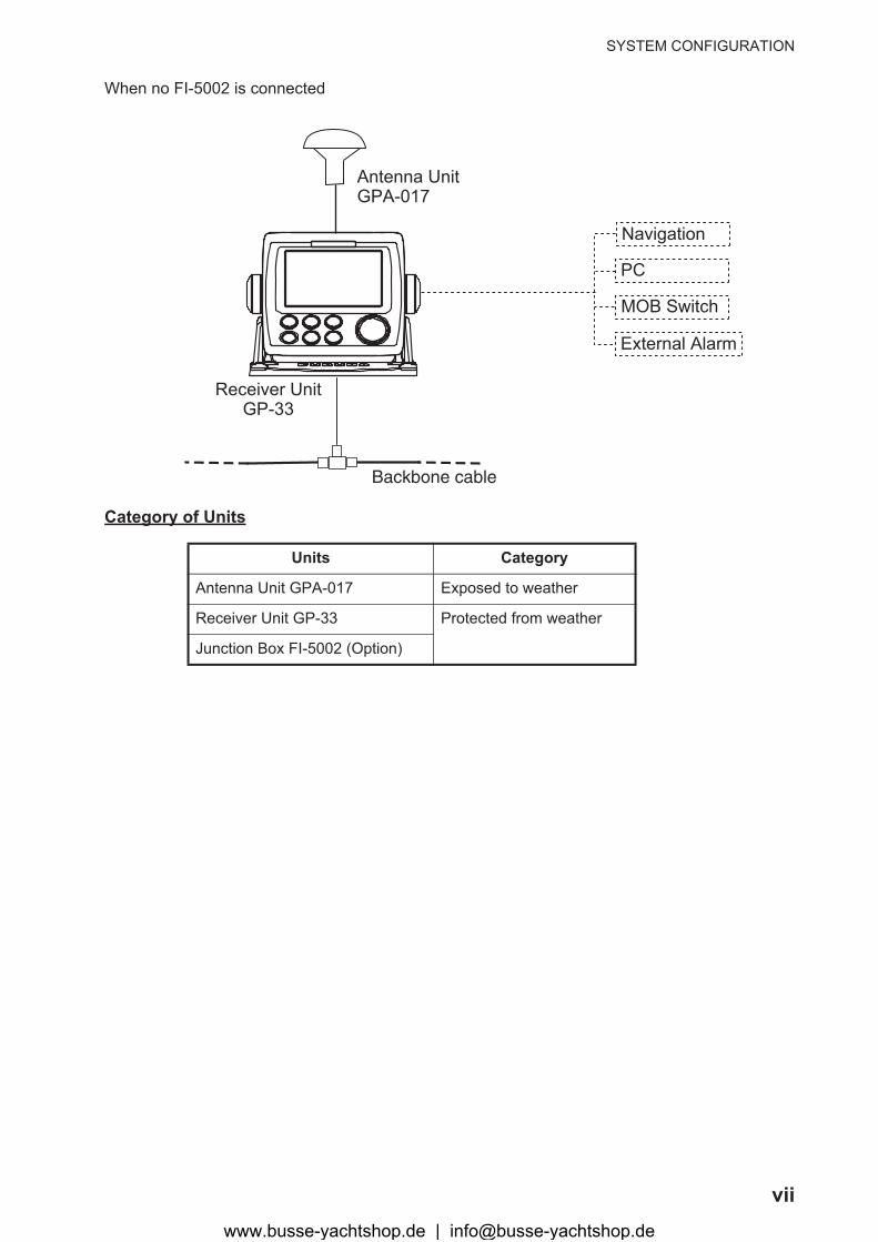
SYSTEM CONFIGURATION
vii
When no FI-5002 is connected
Category of Units
Units Category
Antenna Unit GPA-017 Exposed to weather
Receiver Unit GP-33 Protected from weather
Junction Box FI-5002 (Option)
Receiver UnitGP-33
Antenna UnitGPA-017
Backbone cable
Navigation
PC
MOB Switch
External Alarm
www.busse-yachtshop.de | [email protected]

SYSTEM CONFIGURATION
viii
This page is intentionally left blank.
www.busse-yachtshop.de | [email protected]
1-1
1. OPERATIONAL OVERVIEW
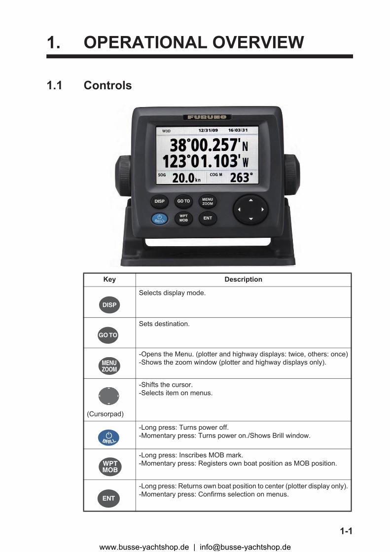
1.1 Controls
Key Description
Selects display mode.
Sets destination.
-Opens the Menu. (plotter and highway displays: twice, others: once)-Shows the zoom window (plotter and highway displays only).
(Cursorpad)
-Shifts the cursor.-Selects item on menus.
-Long press: Turns power off.-Momentary press: Turns power on./Shows Brill window.
-Long press: Inscribes MOB mark.-Momentary press: Registers own boat position as MOB position.
-Long press: Returns own boat position to center (plotter display only).-Momentary press: Confirms selection on menus.
W3D
DISP
GO TO
MENUZOOM
BRILL
WPTMOB
ENT
www.busse-yachtshop.de | [email protected]
1. OPERATIONAL OVERVIEW
1-2
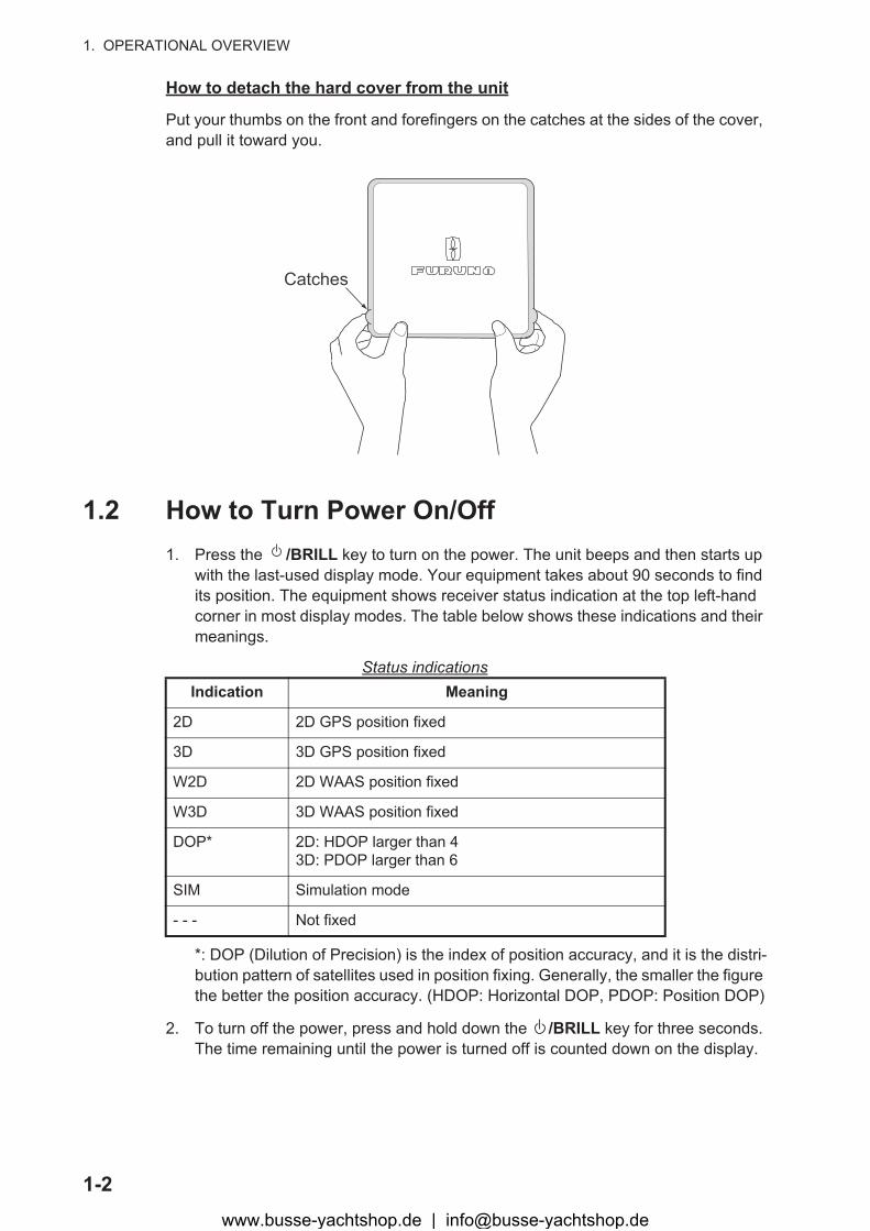
How to detach the hard cover from the unit
Put your thumbs on the front and forefingers on the catches at the sides of the cover, and pull it toward you.
1.2 How to Turn Power On/Off1. Press the /BRILL key to turn on the power. The unit beeps and then starts up
with the last-used display mode. Your equipment takes about 90 seconds to find its position. The equipment shows receiver status indication at the top left-hand corner in most display modes. The table below shows these indications and their meanings.
Status indications
*: DOP (Dilution of Precision) is the index of position accuracy, and it is the distri-bution pattern of satellites used in position fixing. Generally, the smaller the figure the better the position accuracy. (HDOP: Horizontal DOP, PDOP: Position DOP)
2. To turn off the power, press and hold down the /BRILL key for three seconds.The time remaining until the power is turned off is counted down on the display.
Indication Meaning
2D 2D GPS position fixed
3D 3D GPS position fixed
W2D 2D WAAS position fixed
W3D 3D WAAS position fixed
DOP* 2D: HDOP larger than 43D: PDOP larger than 6
SIM Simulation mode
- - - Not fixed
Catches
www.busse-yachtshop.de | [email protected]
1. OPERATIONAL OVERVIEW
1-3
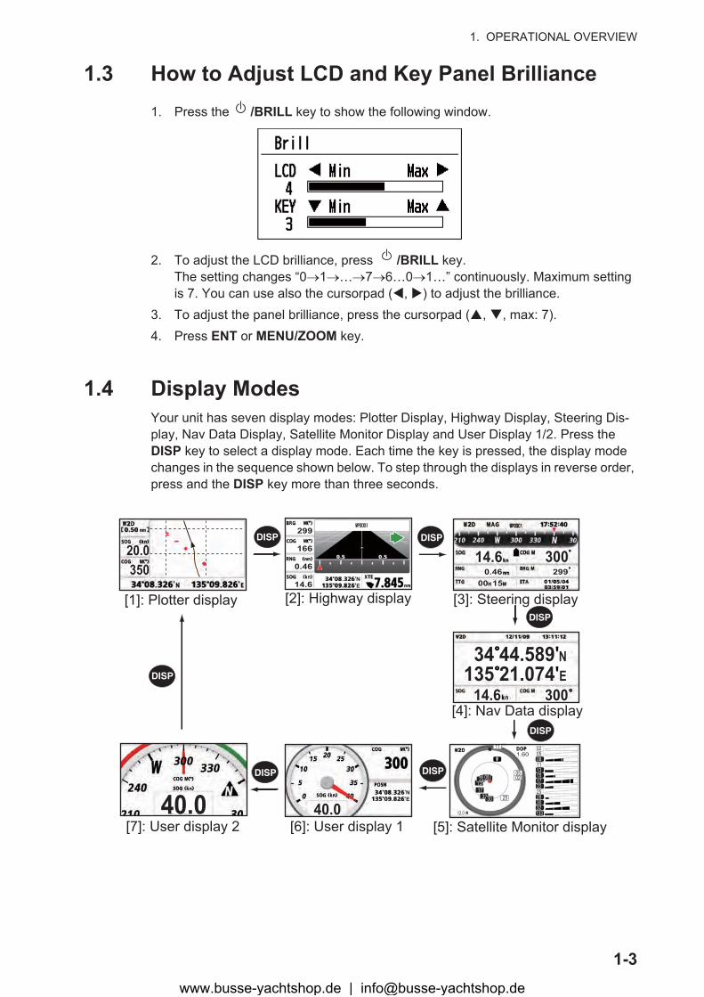
1.3 How to Adjust LCD and Key Panel Brilliance1. Press the /BRILL key to show the following window.
2. To adjust the LCD brilliance, press /BRILL key.The setting changes “0�1�…�7�6…0�1…” continuously. Maximum setting is 7. You can use also the cursorpad (�, �) to adjust the brilliance.
3. To adjust the panel brilliance, press the cursorpad (�, �, max: 7).4. Press ENT or MENU/ZOOM key.
1.4 Display ModesYour unit has seven display modes: Plotter Display, Highway Display, Steering Dis-play, Nav Data Display, Satellite Monitor Display and User Display 1/2. Press the DISP key to select a display mode. Each time the key is pressed, the display mode changes in the sequence shown below. To step through the displays in reverse order, press and the DISP key more than three seconds.
DISP DISP
DISP
DISP
DISPDISP
DISP
[1]: Plotter display
20.0350
[2]: Highway display
299
166
0.46
14.6NE
[3]: Steering display
14.6 3000.46 299
00 15
[4]: Nav Data display14.6 300
135 21.07434 44.589 N
E
[5]: Satellite Monitor display[6]: User display 140.0
NE
[7]: User display 240.0
1.60
12.0 133323028252217151311080502
0502
25
0502
323017132208
11
www.busse-yachtshop.de | [email protected]
1. OPERATIONAL OVERVIEW
1-4
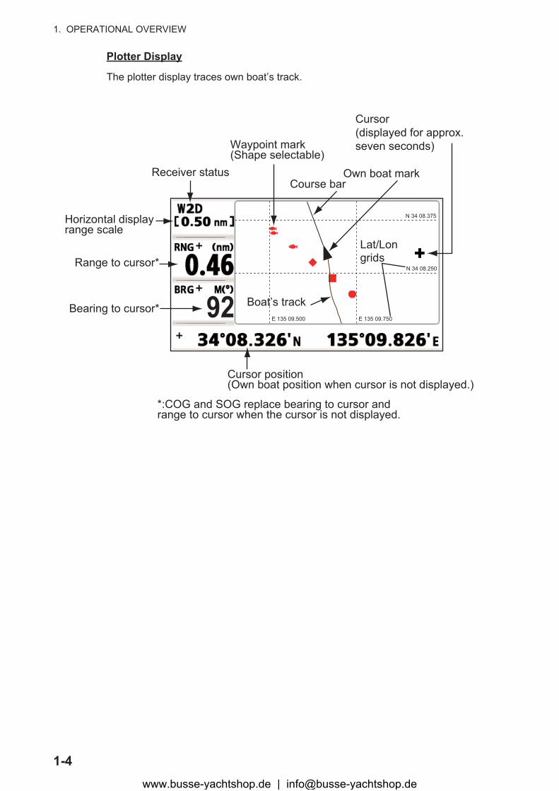
Plotter Display
The plotter display traces own boat’s track.
Receiver status
Waypoint mark(Shape selectable)
Horizontal displayrange scale
Bearing to cursor*
Range to cursor*
*:COG and SOG replace bearing to cursor and range to cursor when the cursor is not displayed.
Cursor position(Own boat position when cursor is not displayed.)
Own boat markCourse bar
Cursor(displayed for approx. seven seconds)
92
N 34 08.375
N 34 08.250
E 135 09.750E 135 09.500
Lat/Longrids
Boat’s track
www.busse-yachtshop.de | [email protected]
1. OPERATIONAL OVERVIEW
1-5
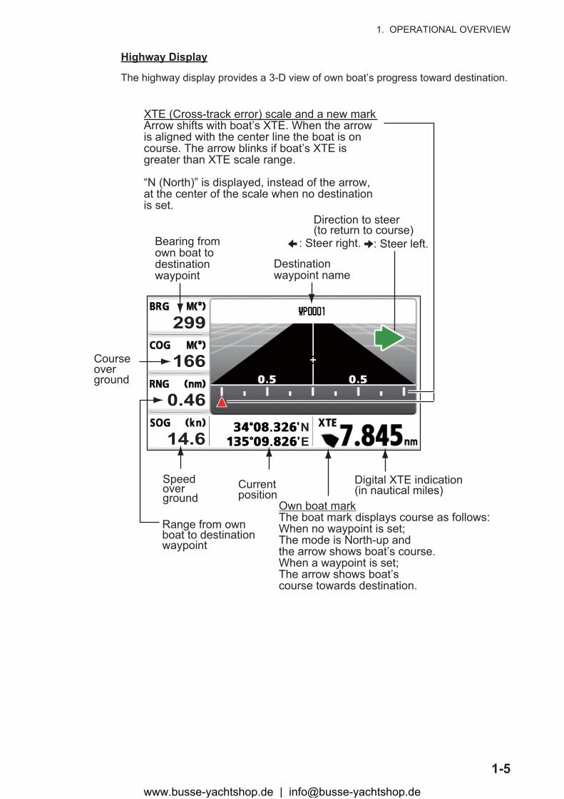
Highway Display
The highway display provides a 3-D view of own boat’s progress toward destination.
Bearing fromown boat to destination waypoint
Speed overground
Course over ground
Digital XTE indication(in nautical miles)
Range from own boat to destinationwaypoint
Own boat markThe boat mark displays course as follows:When no waypoint is set;The mode is North-up and the arrow shows boat’s course.When a waypoint is set;The arrow shows boat’scourse towards destination.
Direction to steer (to return to course)
Current position
299
166
0.46
14.6NE
Destination waypoint name
XTE (Cross-track error) scale and a new markArrow shifts with boat’s XTE. When the arrow is aligned with the center line the boat is on course. The arrow blinks if boat’s XTE is greater than XTE scale range.
“N (North)” is displayed, instead of the arrow, at the center of the scale when no destination is set.
: Steer right. : Steer left.
www.busse-yachtshop.de | [email protected]
1. OPERATIONAL OVERVIEW
1-6
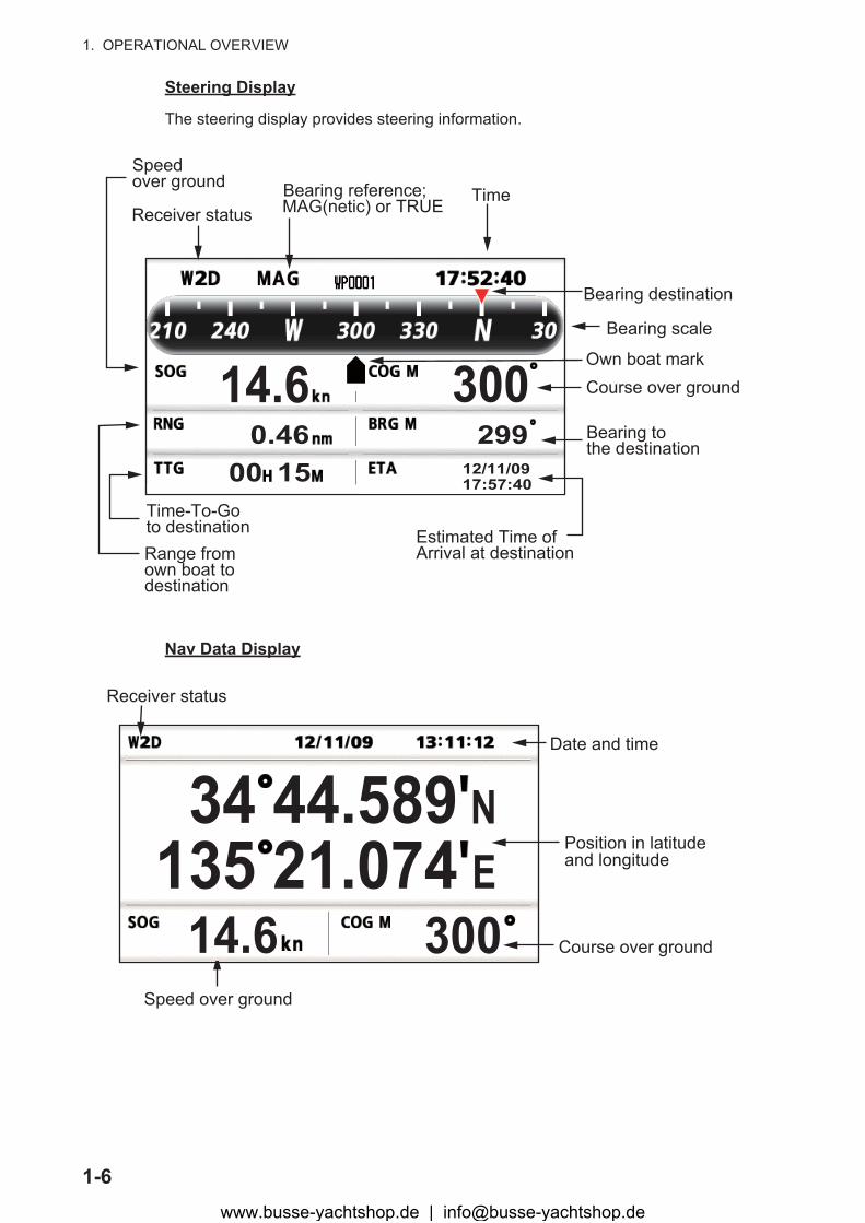
Steering Display
The steering display provides steering information.
Nav Data Display
14.6 3000.46 299
00 15Time-To-Goto destination
TimeReceiver status
Speed over ground Bearing reference;
MAG(netic) or TRUE
Range from own boat to destination
Own boat mark
Bearing scale
Estimated Time of Arrival at destination
Bearing to the destination
Course over ground
Bearing destination
12/11/0917:57:40
Speed over ground
14.6 300135 21.07434 44.589 N
E
Receiver status
Date and time
Position in latitude and longitude
Course over ground
www.busse-yachtshop.de | [email protected]

1. OPERATIONAL OVERVIEW
1-7
Satellite Monitor Display
The satellite monitor display shows the condition of GPS and GEO (WAAS) satellites. Number, bearing and elevation angle of all GPS and GEO satellites (if applicable) in view of your receiver appear.
User Display 1, User Display 2
• Digital displayThe digital display shows digital navigation data. You can select what data to dis-play in one to four cells. The choices of data are time, date, speed over ground, cross-track-error, odometer distance, position, course over ground, time-to-go to destination, trip distance, power source voltage, range and bearing to waypoint and estimated time of arrival at destination.
• Speedometer displayThe speedometer display provides both digital and analog displays of speed over ground.
• COG displayThe COG display shows both analog course over ground, and digital speed over ground.
Receiver signal levelBars show signal level.Satellites whose signallevel are highare used infixing position.
DOP value
Elevation45
Elevation 5Altitude Satellite numbers in
reverse video are used for positioning.
Receiverstatus
1.60
12.0 133323028252217151311080502
0502
25
0502
323017132208
11
GEO satellite
Area not used for positioning(set at menu)
Digital display (four cells) Speedometer display COG display40.0
NE 40.0
23.9 15.855.7 335
(default: User display 1) (default: User display 2)
www.busse-yachtshop.de | [email protected]
1. OPERATIONAL OVERVIEW
1-8
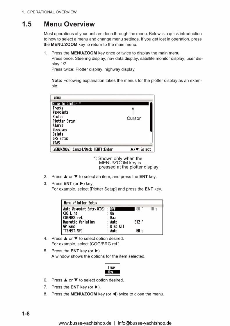
1.5 Menu OverviewMost operations of your unit are done through the menu. Below is a quick introduction to how to select a menu and change menu settings. If you get lost in operation, press the MENU/ZOOM key to return to the main menu.
1. Press the MENU/ZOOM key once or twice to display the main menu.Press once: Steering display, nav data display, satellite monitor display, user dis-play 1/2.Press twice: Plotter display, highway display
Note: Following explanation takes the menus for the plotter display as an exam-ple.
2. Press � or � to select an item, and press the ENT key.3. Press ENT (or �) key.
For example, select [Plotter Setup] and press the ENT key.
4. Press � or � to select option desired.For example, select [COG/BRG ref.]
5. Press the ENT key (or �).A window shows the options for the item selected.
6. Press � or � to select option desired.7. Press the ENT key (or �).8. Press the MENU/ZOOM key (or �) twice to close the menu.
Cursor
*
*: Shown only when the MENU/ZOOM key is pressed at the plotter display.
www.busse-yachtshop.de | [email protected]
1. OPERATIONAL OVERVIEW
1-9
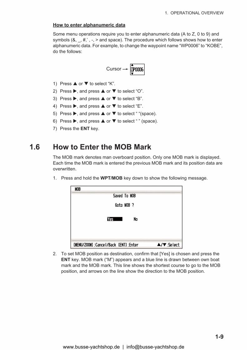
How to enter alphanumeric data
Some menu operations require you to enter alphanumeric data (A to Z, 0 to 9) and symbols (&, _, #,’ , -, > and space). The procedure which follows shows how to enter alphanumeric data. For example, to change the waypoint name “WP0006” to “KOBE”, do the follows:
1) Press � or � to select “K”.2) Press �, and press � or � to select “O”.3) Press �, and press � or � to select “B”.4) Press �, and press � or � to select “E”.5) Press �, and press � or � to select “ “(space).6) Press �, and press � or � to select “ ” (space).7) Press the ENT key.
1.6 How to Enter the MOB MarkThe MOB mark denotes man overboard position. Only one MOB mark is displayed. Each time the MOB mark is entered the previous MOB mark and its position data are overwritten.
1. Press and hold the WPT/MOB key down to show the following message.
2. To set MOB position as destination, confirm that [Yes] is chosen and press the ENT key. MOB mark (“M”) appears and a blue line is drawn between own boat mark and the MOB mark. This line shows the shortest course to go to the MOB position, and arrows on the line show the direction to the MOB position.
Cursor
www.busse-yachtshop.de | [email protected]

1. OPERATIONAL OVERVIEW
1-10
Range from own boat to MOB positionBearing from own boat to MOB position
MOB mark(red)
Shortest course from own boat to MOB position (blue)
N 34 08.500
N 34 08.375
E 135 10.000E 135 09.75095
0.20
www.busse-yachtshop.de | [email protected]

2-1
2. PLOTTER DISPLAY OVERVIEW
2.1 How to Select the Display RangeYou can change the display range on the plotter and highway displays. The horizontal range in the plotter display is available among 0.02, 0.05, 0.1, 0.2, 0.5, 1, 2, 5, 10, 20, 40, 80, 160 and 320 nautical miles. The horizontal range in the highway display is available among 0.2, 0.4, 0.8, 1, 2, 4, 8 and 16 nautical miles.
1. Press the MENU/ZOOM key on the plotter or highway display.The following window appears.
2. Press � or � to select range you want.3. Press the ENT key.
2.2 How to Shift the CursorUse the cursorpad to shift the cursor. The cursor moves in the direction of the arrow or diagonal.
Cursor state and position indication
The position indication, shown at bottom of the plotter display, changes according to cursor state.
Cursor at rest
When the cursor is at rest, boat’s position in longitude and latitude or TDs (depending on the menu setting) appears at the bottom of the display.
(Plotter display) (Highway display)
Own boat’s positionin latitude and longitude
Own boatCOG
(course over ground)
SOG(speed over ground)
COG line
20.0350
www.busse-yachtshop.de | [email protected]

2. PLOTTER DISPLAY OVERVIEW
2-2
Cursor state and position indication
Cursor position is displayed in latitude and longitude or TDs at the bottom of the plotter display when the cursor is in motion.
If there is no operation for about seven seconds, the cursor disappears.
2.3 How to Shift the DisplayThe display can be shifted on the plotter display.
1. Press the cursorpad to show the cursor.2. Press and hold down an arrow on the cursorpad.
When the cursor is placed at an edge of the screen, the display shifts in the direc-tion opposite to cursorpad operation.
Centering own boat’s position
When own boat tracks off the plotter display, the own boat mark is automatically re-turned to the screen center. You can also return it manually by pressing and holding the ENT key for more than three seconds.
Bearing from own boat to cursor
Range from own boat to cursor
Cursor position inlatitude and longitude
Own boat’s mark
COG line
Cursor92
www.busse-yachtshop.de | [email protected]
2. PLOTTER DISPLAY OVERVIEW
2-3
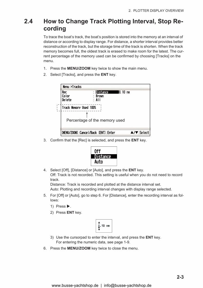
2.4 How to Change Track Plotting Interval, Stop Re-cordingTo trace the boat’s track, the boat’s position is stored into the memory at an interval of distance or according to display range. For distance, a shorter interval provides better reconstruction of the track, but the storage time of the track is shorten. When the track memory becomes full, the oldest track is erased to make room for the latest. The cur-rent percentage of the memory used can be confirmed by choosing [Tracks] on the menu.
1. Press the MENU/ZOOM key twice to show the main menu.2. Select [Tracks], and press the ENT key.
3. Confirm that the [Rec] is selected, and press the ENT key.
4. Select [Off], [Distance] or [Auto], and press the ENT key.Off: Track is not recorded. This setting is useful when you do not need to record track.Distance: Track is recorded and plotted at the distance interval set.Auto: Plotting and recording interval changes with display range selected.
5. For [Off] or [Auto], go to step 6. For [Distance], enter the recording interval as fol-lows:1) Press �.2) Press ENT key.
3) Use the cursorpad to enter the interval, and press the ENT key.For entering the numeric data, see page 1-9.
6. Press the MENU/ZOOM key twice to close the menu.
Percentage of the memory used
www.busse-yachtshop.de | [email protected]
2. PLOTTER DISPLAY OVERVIEW
2-4
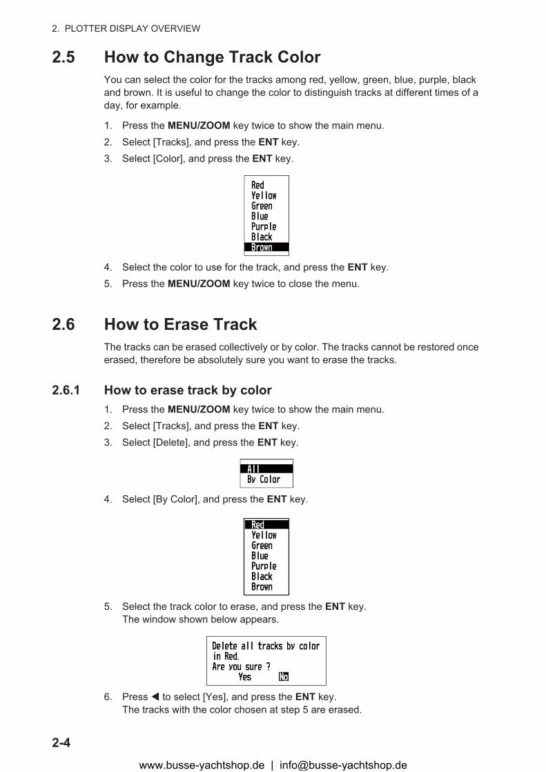
2.5 How to Change Track ColorYou can select the color for the tracks among red, yellow, green, blue, purple, black and brown. It is useful to change the color to distinguish tracks at different times of a day, for example.
1. Press the MENU/ZOOM key twice to show the main menu.2. Select [Tracks], and press the ENT key.3. Select [Color], and press the ENT key.
4. Select the color to use for the track, and press the ENT key.5. Press the MENU/ZOOM key twice to close the menu.
2.6 How to Erase TrackThe tracks can be erased collectively or by color. The tracks cannot be restored once erased, therefore be absolutely sure you want to erase the tracks.
2.6.1 How to erase track by color1. Press the MENU/ZOOM key twice to show the main menu.2. Select [Tracks], and press the ENT key.3. Select [Delete], and press the ENT key.
4. Select [By Color], and press the ENT key.
5. Select the track color to erase, and press the ENT key.The window shown below appears.
6. Press � to select [Yes], and press the ENT key.The tracks with the color chosen at step 5 are erased.
www.busse-yachtshop.de | [email protected]
2. PLOTTER DISPLAY OVERVIEW
2-5
Note: To cancel, select [No] at this step.7. Press the MENU/ZOOM key twice to close the menu.
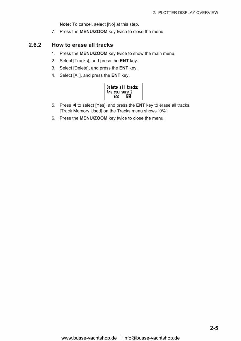
2.6.2 How to erase all tracks1. Press the MENU/ZOOM key twice to show the main menu.2. Select [Tracks], and press the ENT key.3. Select [Delete], and press the ENT key.4. Select [All], and press the ENT key.
5. Press � to select [Yes], and press the ENT key to erase all tracks.[Track Memory Used] on the Tracks menu shows “0%”.
6. Press the MENU/ZOOM key twice to close the menu.
www.busse-yachtshop.de | [email protected]
2. PLOTTER DISPLAY OVERVIEW
2-6
This page is intentionally left blank.
www.busse-yachtshop.de | [email protected]

3-1
3. WAYPOINTS
3.1 How to Enter WaypointsIn navigation terminology a waypoint is a particular location on a voyage, whether it be a starting, intermediate or destination waypoint. Your unit can store 10,000 way-points. Waypoints can be entered on the plotter display: at cursor position, at own boat’s position, through the waypoints list and at the MOB position. Also, waypoints can be entered automatically when your boat changes course prominently.
3.1.1 How to enter a waypoint with the cursor1. Use the cursorpad to place the cursor on the location desired for a waypoint.2. Press the ENT key to enter the waypoint mark (default shape: green solid circle).
This waypoint is named with the youngest unused waypoint number, and saved to the waypoint list.
3.1.2 How to enter a waypoint at own boat positionPress the WPT/MOB key to enter the waypoint mark (default shape: green solid cir-cle). This waypoint is named with the youngest unused waypoint number, and saved to the waypoint list.
3.1.3 How to enter a waypoint through the list1. Press the MENU/ZOOM key to show the main menu.2. Select [Waypoints], and press the ENT key.
3. Press the ENT key to show the waypoint list.
www.busse-yachtshop.de | [email protected]
3. WAYPOINTS
3-2
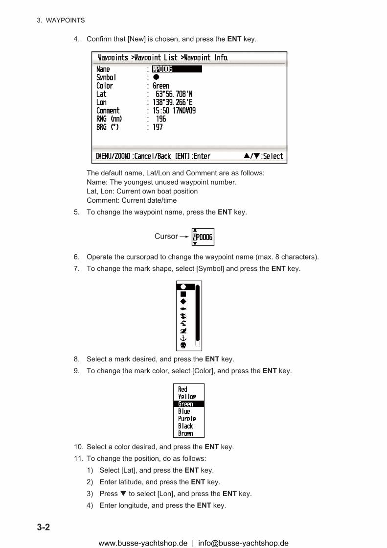
4. Confirm that [New] is chosen, and press the ENT key.
The default name, Lat/Lon and Comment are as follows:Name: The youngest unused waypoint number.Lat, Lon: Current own boat positionComment: Current date/time
5. To change the waypoint name, press the ENT key.
6. Operate the cursorpad to change the waypoint name (max. 8 characters).7. To change the mark shape, select [Symbol] and press the ENT key.
8. Select a mark desired, and press the ENT key.9. To change the mark color, select [Color], and press the ENT key.
10. Select a color desired, and press the ENT key.11. To change the position, do as follows:
1) Select [Lat], and press the ENT key.2) Enter latitude, and press the ENT key.3) Press � to select [Lon], and press the ENT key.4) Enter longitude, and press the ENT key.
Cursor
www.busse-yachtshop.de | [email protected]
3. WAYPOINTS
3-3
12. To change the comment, select [Comment] and press the ENT key. 13. Enter the comment, and press the ENT key.14. Press the MENU/ZOOM key to register the new waypoint into the list.15. To register other waypoints, repeat steps 4 through 12.16. Press the MENU/ZOOM key several times to close the menu.
3.1.4 How to enter waypoints automaticallyWaypoints can be entered automatically when your course changes by a specified de-gree. This function is useful for reversely following the waypoints recorded on an out-ward voyage when you return home. To set the criteria for automatic entering of waypoints, do the following:
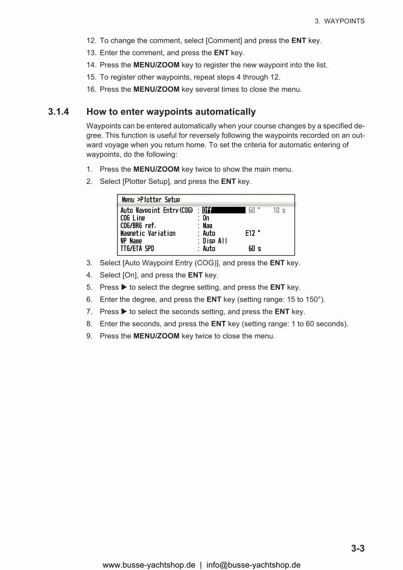
1. Press the MENU/ZOOM key twice to show the main menu.2. Select [Plotter Setup], and press the ENT key.
3. Select [Auto Waypoint Entry (COG)], and press the ENT key.4. Select [On], and press the ENT key.5. Press � to select the degree setting, and press the ENT key.6. Enter the degree, and press the ENT key (setting range: 15 to 150°).7. Press � to select the seconds setting, and press the ENT key.8. Enter the seconds, and press the ENT key (setting range: 1 to 60 seconds).9. Press the MENU/ZOOM key twice to close the menu.
www.busse-yachtshop.de | [email protected]
3. WAYPOINTS
3-4
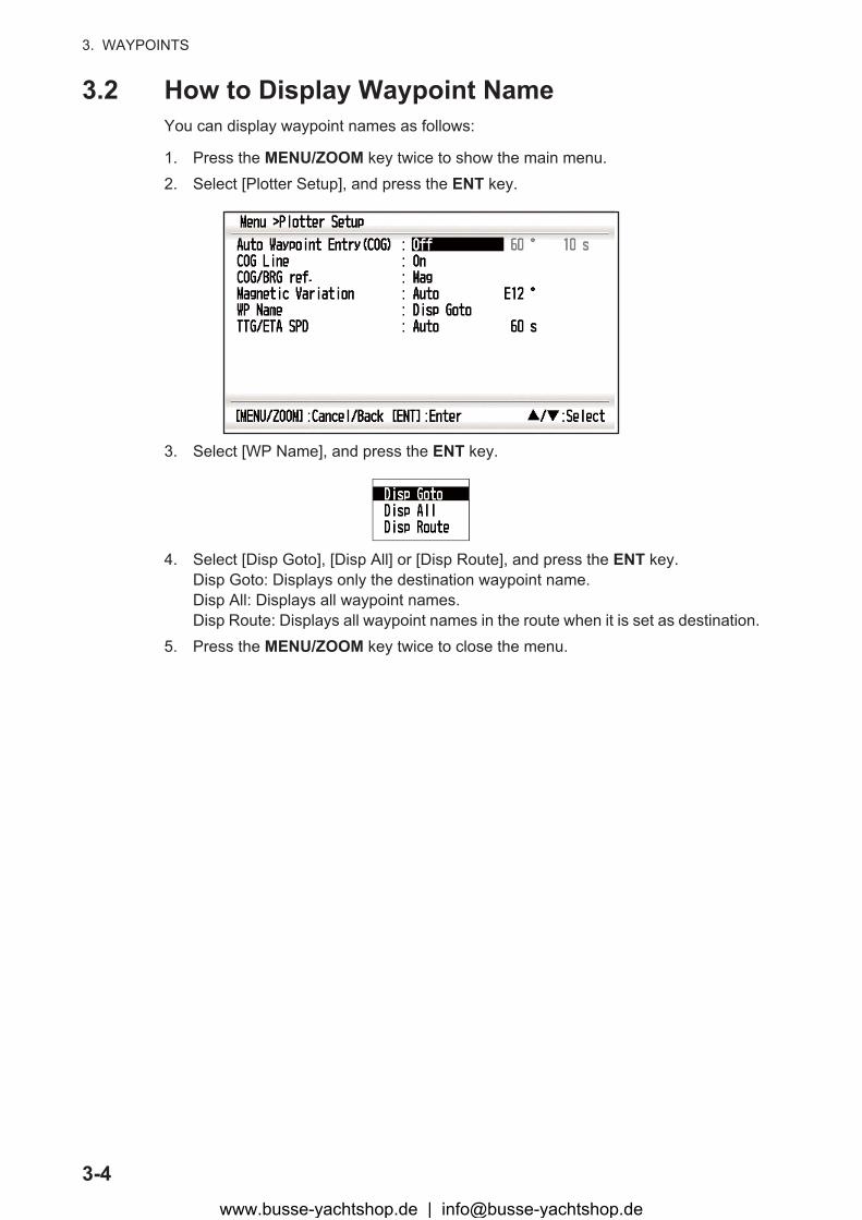
3.2 How to Display Waypoint NameYou can display waypoint names as follows:
1. Press the MENU/ZOOM key twice to show the main menu.2. Select [Plotter Setup], and press the ENT key.
3. Select [WP Name], and press the ENT key.
4. Select [Disp Goto], [Disp All] or [Disp Route], and press the ENT key.Disp Goto: Displays only the destination waypoint name.Disp All: Displays all waypoint names.Disp Route: Displays all waypoint names in the route when it is set as destination.
5. Press the MENU/ZOOM key twice to close the menu.
www.busse-yachtshop.de | [email protected]
3. WAYPOINTS
3-5
3.3 How to Edit WaypointsWaypoint position, name, mark shape and comment can be edited on the plotter dis-play or through the waypoint list.
Note: When the waypoint chosen is set as the destination, the message "Change The Waypoint. Are you sure?" appears.
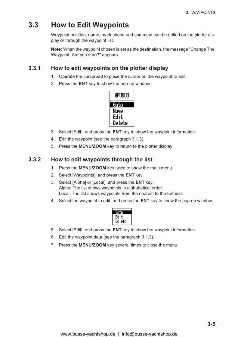
3.3.1 How to edit waypoints on the plotter display1. Operate the cursorpad to place the cursor on the waypoint to edit.2. Press the ENT key to show the pop-up window.
3. Select [Edit], and press the ENT key to show the waypoint information.4. Edit the waypoint (see the paragraph 3.1.3).5. Press the MENU/ZOOM key to return to the plotter display.
3.3.2 How to edit waypoints through the list1. Press the MENU/ZOOM key twice to show the main menu.2. Select [Waypoints], and press the ENT key.3. Select [Alpha] or [Local], and press the ENT key.
Alpha: The list shows waypoints in alphabetical order.Local: The list shows waypoints from the nearest to the furthest.
4. Select the waypoint to edit, and press the ENT key to show the pop-up window.
5. Select [Edit], and press the ENT key to show the waypoint information.6. Edit the waypoint data (see the paragraph 3.1.3).
7. Press the MENU/ZOOM key several times to close the menu.
www.busse-yachtshop.de | [email protected]
3. WAYPOINTS
3-6
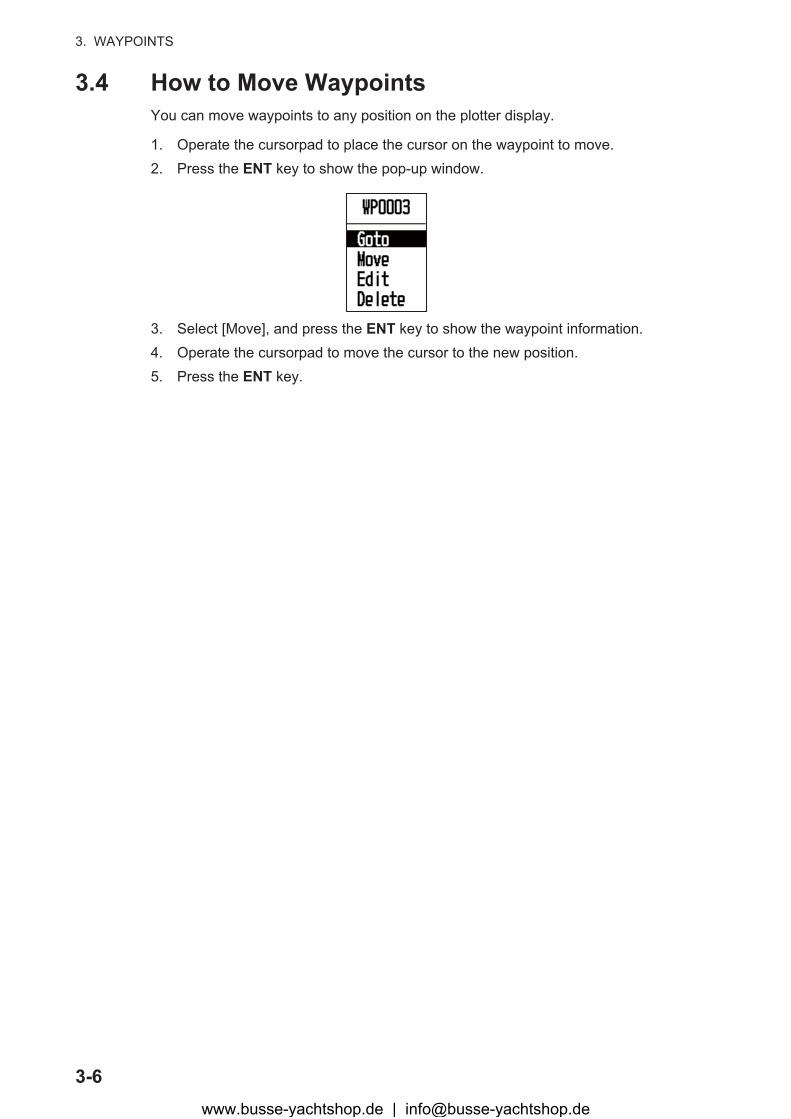
3.4 How to Move WaypointsYou can move waypoints to any position on the plotter display.
1. Operate the cursorpad to place the cursor on the waypoint to move.2. Press the ENT key to show the pop-up window.
3. Select [Move], and press the ENT key to show the waypoint information.4. Operate the cursorpad to move the cursor to the new position.5. Press the ENT key.
www.busse-yachtshop.de | [email protected]
3. WAYPOINTS
3-7
3.5 How to Erase WaypointsYou can erase each or all waypoint(s).
Note: You cannot erase the waypoint used as the current destination. (See para-graphs paragraph 3.5.1, paragraph 3.5.2.)
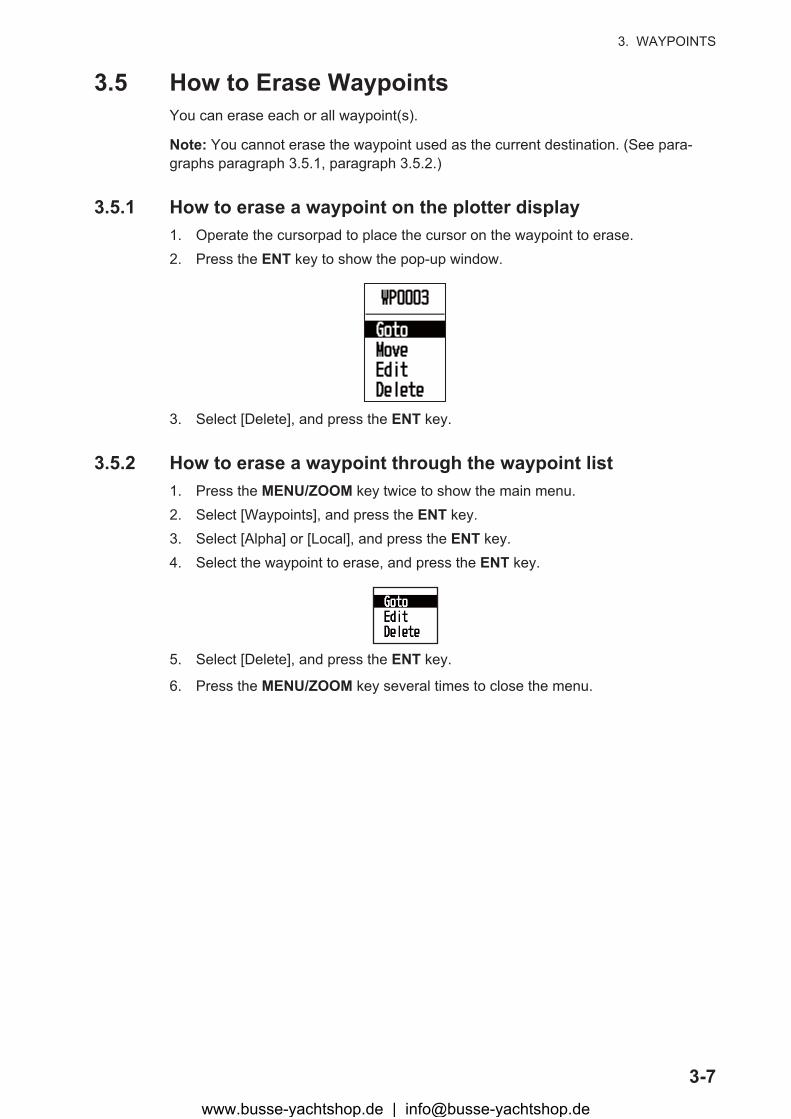
3.5.1 How to erase a waypoint on the plotter display1. Operate the cursorpad to place the cursor on the waypoint to erase.2. Press the ENT key to show the pop-up window.
3. Select [Delete], and press the ENT key.
3.5.2 How to erase a waypoint through the waypoint list1. Press the MENU/ZOOM key twice to show the main menu.2. Select [Waypoints], and press the ENT key.3. Select [Alpha] or [Local], and press the ENT key.4. Select the waypoint to erase, and press the ENT key.
5. Select [Delete], and press the ENT key.
6. Press the MENU/ZOOM key several times to close the menu.
www.busse-yachtshop.de | [email protected]
3. WAYPOINTS
3-8
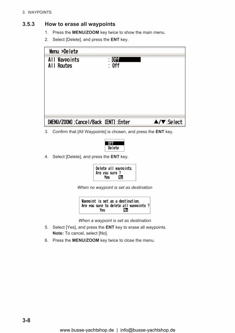
3.5.3 How to erase all waypoints1. Press the MENU/ZOOM key twice to show the main menu.2. Select [Delete], and press the ENT key.
3. Confirm that [All Waypoints] is chosen, and press the ENT key.
4. Select [Delete], and press the ENT key.
When no waypoint is set as destination
When a waypoint is set as destination5. Select [Yes], and press the ENT key to erase all waypoints.
Note: To cancel, select [No].6. Press the MENU/ZOOM key twice to close the menu.
www.busse-yachtshop.de | [email protected]
4-1
4. ROUTES
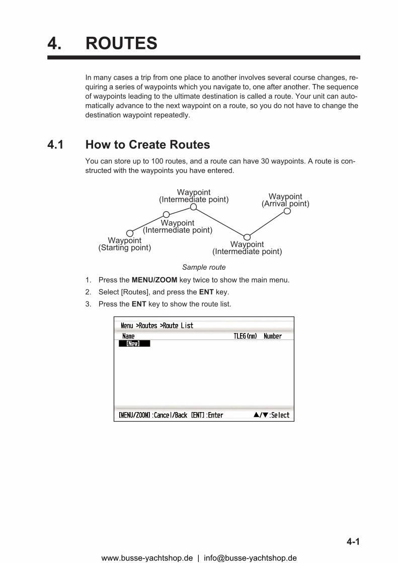
In many cases a trip from one place to another involves several course changes, re-quiring a series of waypoints which you navigate to, one after another. The sequence of waypoints leading to the ultimate destination is called a route. Your unit can auto-matically advance to the next waypoint on a route, so you do not have to change the destination waypoint repeatedly.
4.1 How to Create RoutesYou can store up to 100 routes, and a route can have 30 waypoints. A route is con-structed with the waypoints you have entered.
Sample route
1. Press the MENU/ZOOM key twice to show the main menu.2. Select [Routes], and press the ENT key.3. Press the ENT key to show the route list.
Waypoint(Intermediate point)
Waypoint(Starting point)
Waypoint(Intermediate point)
Waypoint(Intermediate point)
Waypoint(Arrival point)
www.busse-yachtshop.de | [email protected]
4. ROUTES
4-2
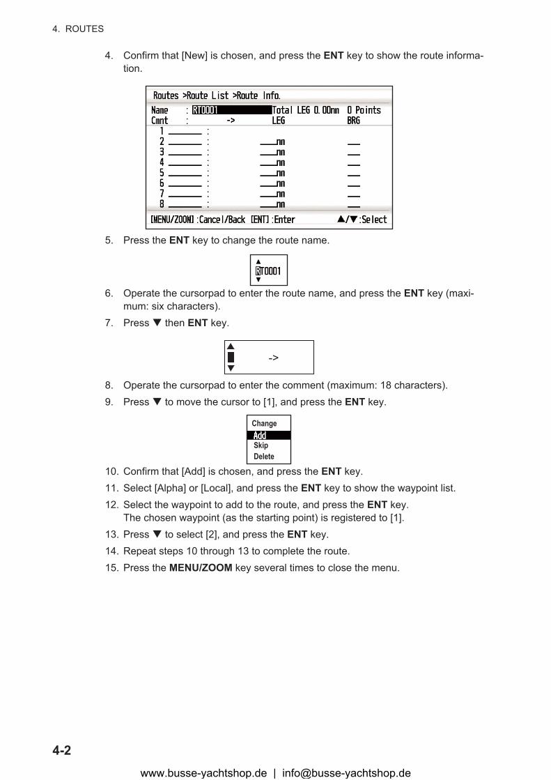
4. Confirm that [New] is chosen, and press the ENT key to show the route informa-tion.
5. Press the ENT key to change the route name.
6. Operate the cursorpad to enter the route name, and press the ENT key (maxi-mum: six characters).
7. Press � then ENT key.
8. Operate the cursorpad to enter the comment (maximum: 18 characters).9. Press � to move the cursor to [1], and press the ENT key.
10. Confirm that [Add] is chosen, and press the ENT key.11. Select [Alpha] or [Local], and press the ENT key to show the waypoint list.12. Select the waypoint to add to the route, and press the ENT key.
The chosen waypoint (as the starting point) is registered to [1].13. Press � to select [2], and press the ENT key.14. Repeat steps 10 through 13 to complete the route.15. Press the MENU/ZOOM key several times to close the menu.
->
Change
SkipDelete
www.busse-yachtshop.de | [email protected]
4. ROUTES
4-3
4.2 How to Edit RoutesYou can edit the route created.
Note: When the route chosen is set as the destination, the message "Route is set as a destination. Are you sure?" appears.
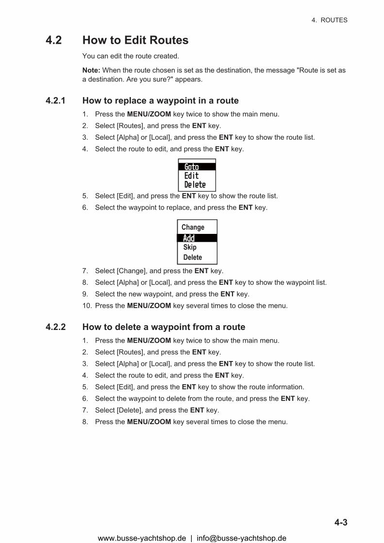
4.2.1 How to replace a waypoint in a route1. Press the MENU/ZOOM key twice to show the main menu.2. Select [Routes], and press the ENT key.3. Select [Alpha] or [Local], and press the ENT key to show the route list.4. Select the route to edit, and press the ENT key.
5. Select [Edit], and press the ENT key to show the route list.6. Select the waypoint to replace, and press the ENT key.
7. Select [Change], and press the ENT key.8. Select [Alpha] or [Local], and press the ENT key to show the waypoint list.9. Select the new waypoint, and press the ENT key.10. Press the MENU/ZOOM key several times to close the menu.
4.2.2 How to delete a waypoint from a route1. Press the MENU/ZOOM key twice to show the main menu.2. Select [Routes], and press the ENT key.3. Select [Alpha] or [Local], and press the ENT key to show the route list.4. Select the route to edit, and press the ENT key.5. Select [Edit], and press the ENT key to show the route information.6. Select the waypoint to delete from the route, and press the ENT key.7. Select [Delete], and press the ENT key.8. Press the MENU/ZOOM key several times to close the menu.
Change
SkipDelete
www.busse-yachtshop.de | [email protected]
4. ROUTES
4-4
4.2.3 How to insert a waypoint in a routeTo insert a waypoint in a route, do the following:
1. Press the MENU/ZOOM key twice to show the main menu.2. Select [Routes], and press the ENT key.3. Select [Alpha] or [Local], and press the ENT key to show the route list.4. Select the route to edit, and press the ENT key.5. Select [Edit], and press the ENT key to show the route list.6. Select the waypoint which will come after the waypoint to be inserted, and press
the ENT key.7. Select [Add], and press the ENT key.8. Select [Alpha] or [Local], and press the ENT key to show the waypoint list.9. Select the waypoint, and press the ENT key.10. Press the MENU/ZOOM key several times to close the menu.
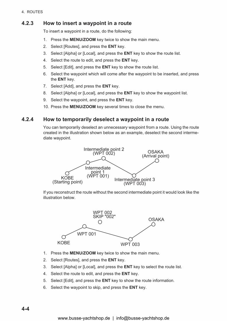
4.2.4 How to temporarily deselect a waypoint in a routeYou can temporarily deselect an unnecessary waypoint from a route. Using the route created in the illustration shown below as an example, deselect the second interme-diate waypoint.
If you reconstruct the route without the second intermediate point it would look like the illustration below.
1. Press the MENU/ZOOM key twice to show the main menu.2. Select [Routes], and press the ENT key.3. Select [Alpha] or [Local], and press the ENT key to select the route list.4. Select the route to edit, and press the ENT key.5. Select [Edit], and press the ENT key to show the route information.6. Select the waypoint to skip, and press the ENT key.
Intermediate point 2(WPT 002)
KOBE(Starting point)
Intermediatepoint 1
(WPT 001)Intermediate point 3
(WPT 003)
OSAKA(Arrival point)
WPT 002SKIP "002"
WPT 001
KOBE WPT 003
OSAKA
www.busse-yachtshop.de | [email protected]
4. ROUTES
4-5
7. Select [Skip], and press the ENT key to show “X” next to the waypoint chosen at step 6.
8. Press the MENU/ZOOM key several times to close the menu.
Note: To restore waypoint to a route, select [Skip Off] at step 7, and press the ENT key.
4.3 How to Erase a RouteYou can erase routes individually or collectively.
4.3.1 How to erase a route through the route listNote: The route used as the destination can not be erased.
1. Press the MENU/ZOOM key twice to show the main menu.2. Select [Routes], and press the ENT key.3. Select [Alpha] or [Local], and press the ENT key to show the route list.4. Select the route to erase, and press the ENT key.5. Select [Delete], and press the ENT key to erase the route chosen at step 4.6. Press the MENU/ZOOM key several times to close the menu.
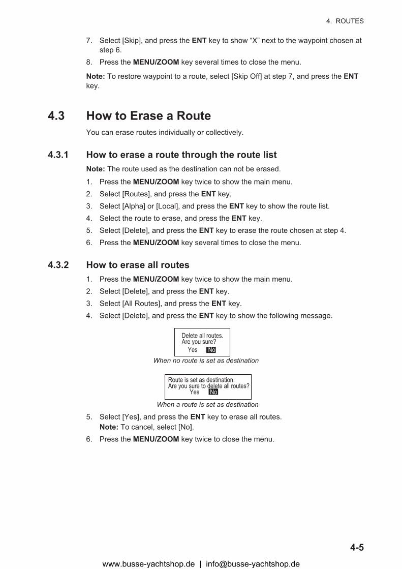
4.3.2 How to erase all routes1. Press the MENU/ZOOM key twice to show the main menu.2. Select [Delete], and press the ENT key.3. Select [All Routes], and press the ENT key.4. Select [Delete], and press the ENT key to show the following message.
5. Select [Yes], and press the ENT key to erase all routes.Note: To cancel, select [No].
6. Press the MENU/ZOOM key twice to close the menu.
Delete all routes.Are you sure? Yes No
Route is set as destination.Are you sure to delete all routes? Yes No
When no route is set as destination
When a route is set as destination
www.busse-yachtshop.de | [email protected]

5-1
5. DESTINATION
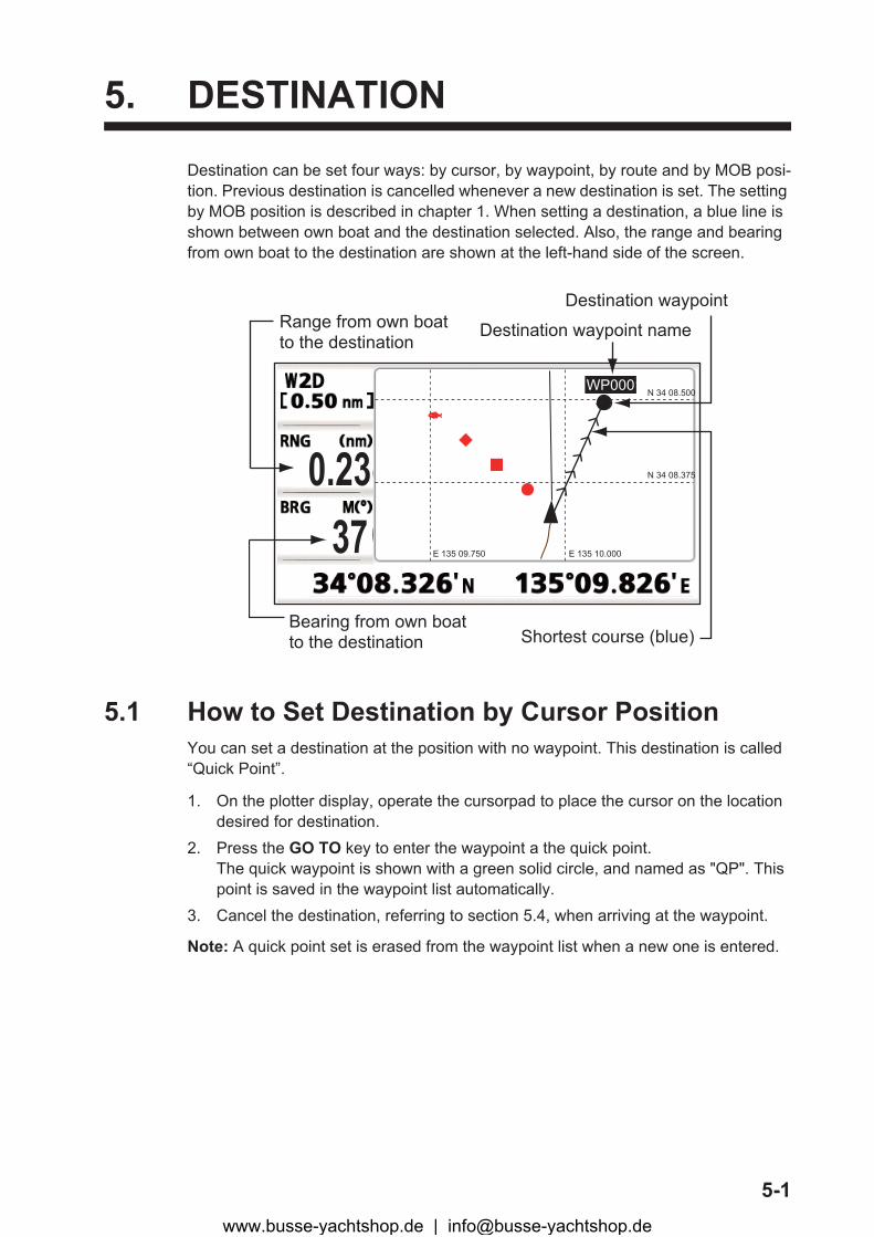
Destination can be set four ways: by cursor, by waypoint, by route and by MOB posi-tion. Previous destination is cancelled whenever a new destination is set. The setting by MOB position is described in chapter 1. When setting a destination, a blue line is shown between own boat and the destination selected. Also, the range and bearing from own boat to the destination are shown at the left-hand side of the screen.
5.1 How to Set Destination by Cursor PositionYou can set a destination at the position with no waypoint. This destination is called “Quick Point”.
1. On the plotter display, operate the cursorpad to place the cursor on the location desired for destination.
2. Press the GO TO key to enter the waypoint a the quick point.The quick waypoint is shown with a green solid circle, and named as "QP". This point is saved in the waypoint list automatically.
3. Cancel the destination, referring to section 5.4, when arriving at the waypoint.
Note: A quick point set is erased from the waypoint list when a new one is entered.
N 34 08.500
N 34 08.375
E 135 10.000E 135 09.75037
Range from own boatto the destination
Bearing from own boatto the destination Shortest course (blue)
0.23
Destination waypoint
WP0001
Destination waypoint name
www.busse-yachtshop.de | [email protected]
5. DESTINATION
5-2
5.2 How to Set Destination by WaypointYou can set a waypoint as destination by using the cursor or the waypoints list.
5.2.1 How to set a destination waypoint with the cursor1. On the plotter display, operate the cursorpad to place the cursor on the waypoint
which you want to set as the destination.2. Press the ENT key.
3. Select [Goto], and press the ENT key.4. Cancel the destination referring to section 5.4 when arriving at the waypoint.
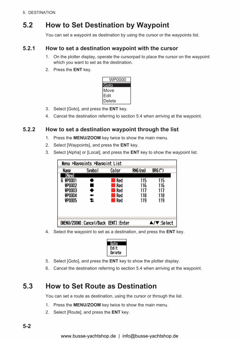
5.2.2 How to set a destination waypoint through the list1. Press the MENU/ZOOM key twice to show the main menu.2. Select [Waypoints], and press the ENT key.3. Select [Alpha] or [Local], and press the ENT key to show the waypoint list.
4. Select the waypoint to set as a destination, and press the ENT key.
5. Select [Goto], and press the ENT key to show the plotter display.6. Cancel the destination referring to section 5.4 when arriving at the waypoint.
5.3 How to Set Route as DestinationYou can set a route as destination, using the cursor or through the list.
1. Press the MENU/ZOOM key twice to show the main menu.2. Select [Route], and press the ENT key.
WP0000GotoMoveEditDelete
www.busse-yachtshop.de | [email protected]

5. DESTINATION
5-3
3. Select [Alpha] or [Local], and press the ENT key.
4. Select the route to set as a destination, and press the ENT key.
5. Select [Goto], and press the ENT key.6. Select [Forward] or [Reverse].
Forward: Follows waypoints in order registered (1�2�3…) Reverse: Follows waypoints in reverse order registered (30 (when maximum en-tered) �29�28…�1)
7. Press the ENT key to show the plotter display. The destination route is shown with waypoints connected with legs.
8. Cancel the destination referring to section 5.4 when arriving at the waypoint.
How to change the following direction after you set a route as destination
After you start doing the route destination, you can change the following direction, [Forward]�[Reverse] or vice versa. Place the cursor on a leg of the route, and press the ENT key to show the following pop-up window. Select [Reverse] (or [Forward]). Then, select [Yes] and press the ENT key.
Note: If your boat has not yet arrived at the first waypoint in the route, the current route destination is cancelled if you select [Reverse] (or [Forward]). Set the route destination again.
5.4 How to Cancel DestinationYou can cancel destination by using the cursor, or through the list.
5.4.1 How to cancel destination with the cursor1. On the plotter display, operate the cursorpad to place the cursor on the waypoint
(route) set as the current destination.
RT000 : WP000 ->WP0001 0.85 2RT001 : WP003 ->WP0001 0.06 2RT002 : WP001 ->WP0005 1.83 3RT003 : WP001 ->WP0004 3.54 4
RT0000Cancel RouteReverseRoute Info.
www.busse-yachtshop.de | [email protected]

5. DESTINATION
5-4
2. Press the ENT key.
3. Select [Cancel Goto (Route)], and press the ENT key.
4. Chose [Yes], and press the ENT key.To cancel, select [No].
5.4.2 How to cancel destination through the list1. Press the MENU/ZOOM key twice to show the main menu.2. Select [Waypoints] (or [Routes]), and press the ENT key twice.3. Select the waypoint (route) set as the current destination.
4. Press the ENT key.
5. Select [Cancel Goto (Route)], and press the ENT key.
6. Select [Yes], and press the ENT key.To cancel, select [No].
7. Press the MENU/ZOOM key several times to close the menu.
RT0000Cancel RouteReverseRoute Info.
WP0001MoveCancel GotoEditDelete
(for waypoint destination) (for route destination)
QP0001MoveCancel GotoEditDelete
(for QP destination)
WP0001
(for route leg)
MoveSkipCancel RouteEdit
Cancel Route Navigation.Are you sure? Yes No
(for route destination)
Cancel Goto.Are you sure? Yes No
(for waypoint destination)
Destination mark
RWaypoint used fordestination route
Cancel RouteEditDelete
Cancel GotoEditDelete
(for waypoint destination) (for route destination)
Cancel Route Navigation.Are you sure? Yes No
(for route destination)
Cancel Goto.Are you sure? Yes No
(for waypoint destination)
www.busse-yachtshop.de | [email protected]
6-1
6. ALARMS
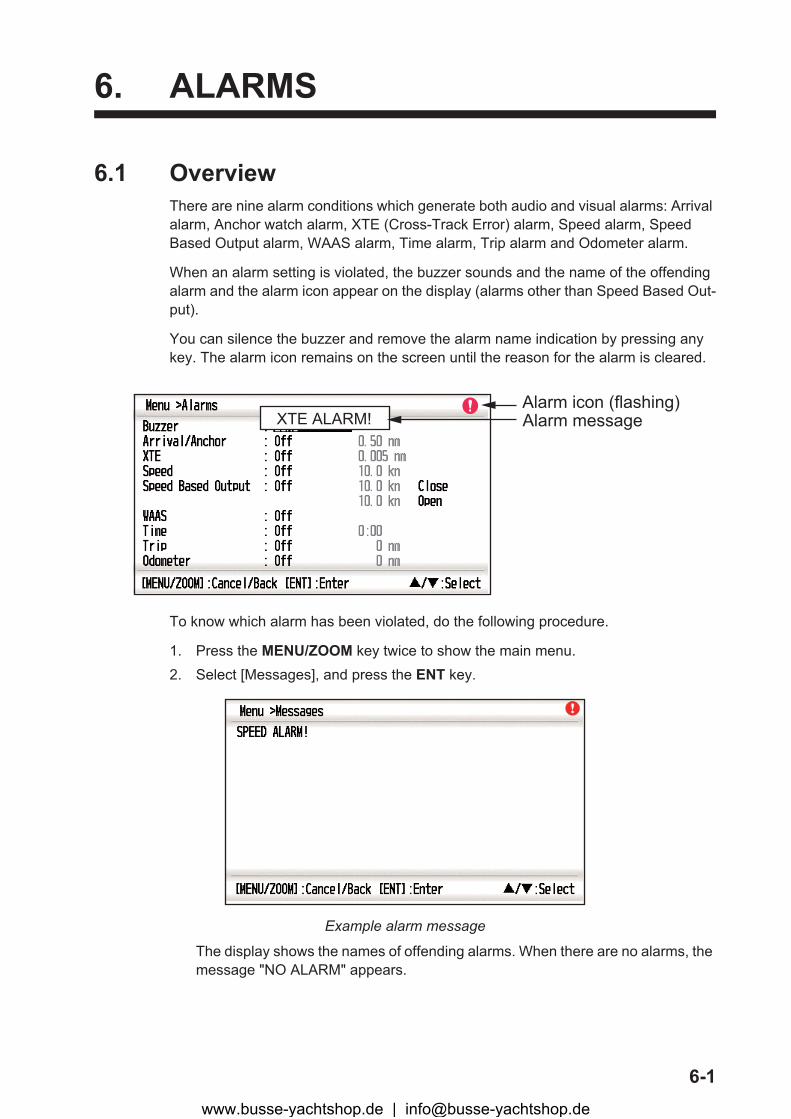
6.1 OverviewThere are nine alarm conditions which generate both audio and visual alarms: Arrival alarm, Anchor watch alarm, XTE (Cross-Track Error) alarm, Speed alarm, Speed Based Output alarm, WAAS alarm, Time alarm, Trip alarm and Odometer alarm.
When an alarm setting is violated, the buzzer sounds and the name of the offending alarm and the alarm icon appear on the display (alarms other than Speed Based Out-put).
You can silence the buzzer and remove the alarm name indication by pressing any key. The alarm icon remains on the screen until the reason for the alarm is cleared.
To know which alarm has been violated, do the following procedure.
1. Press the MENU/ZOOM key twice to show the main menu.2. Select [Messages], and press the ENT key.
Example alarm message
The display shows the names of offending alarms. When there are no alarms, the message "NO ALARM" appears.
Alarm messageAlarm icon (flashing)
XTE ALARM!
www.busse-yachtshop.de | [email protected]
6. ALARMS
6-2
Message and meanings
Note: The message screen also shows equipment trouble. See section 8.3.
6.2 Buzzer Type SelectionThe buzzer sounds whenever an alarm setting is violated. You can select the type of buzzer as follows:
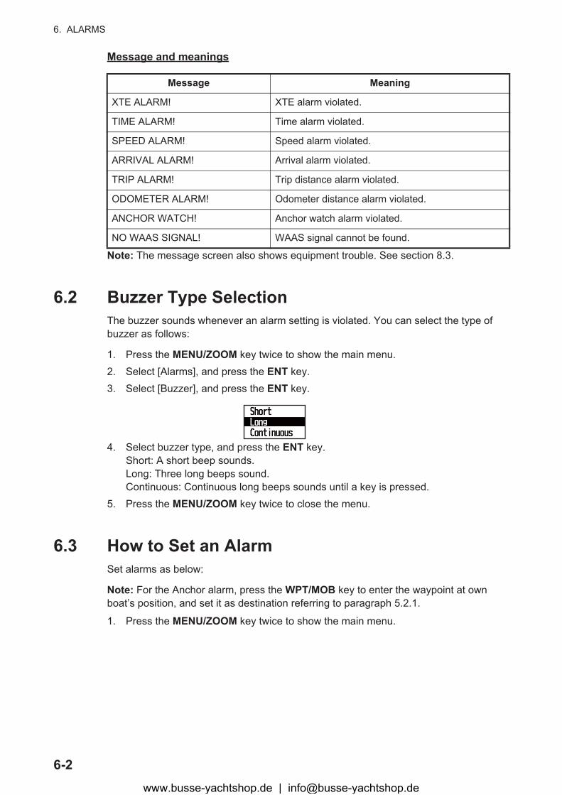
1. Press the MENU/ZOOM key twice to show the main menu.2. Select [Alarms], and press the ENT key.3. Select [Buzzer], and press the ENT key.
4. Select buzzer type, and press the ENT key.Short: A short beep sounds.Long: Three long beeps sound.Continuous: Continuous long beeps sounds until a key is pressed.
5. Press the MENU/ZOOM key twice to close the menu.
6.3 How to Set an AlarmSet alarms as below:
Note: For the Anchor alarm, press the WPT/MOB key to enter the waypoint at own boat’s position, and set it as destination referring to paragraph 5.2.1.
1. Press the MENU/ZOOM key twice to show the main menu.
Message Meaning
XTE ALARM! XTE alarm violated.
TIME ALARM! Time alarm violated.
SPEED ALARM! Speed alarm violated.
ARRIVAL ALARM! Arrival alarm violated.
TRIP ALARM! Trip distance alarm violated.
ODOMETER ALARM! Odometer distance alarm violated.
ANCHOR WATCH! Anchor watch alarm violated.
NO WAAS SIGNAL! WAAS signal cannot be found.
www.busse-yachtshop.de | [email protected]
6. ALARMS
6-3
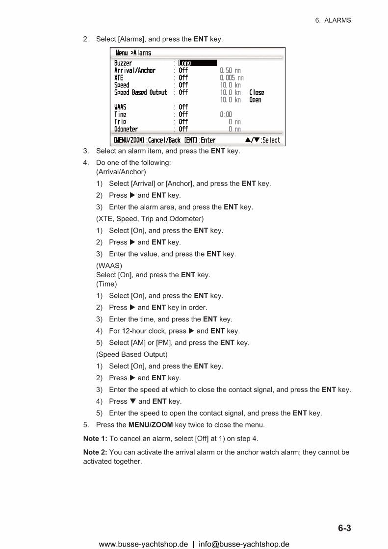
2. Select [Alarms], and press the ENT key.
3. Select an alarm item, and press the ENT key.4. Do one of the following:
(Arrival/Anchor)1) Select [Arrival] or [Anchor], and press the ENT key.2) Press � and ENT key.3) Enter the alarm area, and press the ENT key.(XTE, Speed, Trip and Odometer)1) Select [On], and press the ENT key.2) Press � and ENT key.3) Enter the value, and press the ENT key.(WAAS)Select [On], and press the ENT key.(Time)1) Select [On], and press the ENT key.2) Press � and ENT key in order.3) Enter the time, and press the ENT key.4) For 12-hour clock, press � and ENT key.5) Select [AM] or [PM], and press the ENT key.(Speed Based Output)1) Select [On], and press the ENT key.2) Press � and ENT key.3) Enter the speed at which to close the contact signal, and press the ENT key.4) Press � and ENT key.5) Enter the speed to open the contact signal, and press the ENT key.
5. Press the MENU/ZOOM key twice to close the menu.
Note 1: To cancel an alarm, select [Off] at 1) on step 4.
Note 2: You can activate the arrival alarm or the anchor watch alarm; they cannot be activated together.
www.busse-yachtshop.de | [email protected]
6. ALARMS
6-4
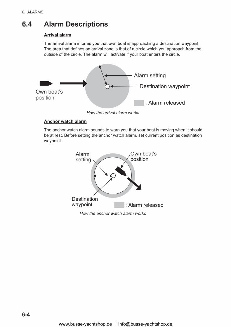
6.4 Alarm DescriptionsArrival alarm
The arrival alarm informs you that own boat is approaching a destination waypoint. The area that defines an arrival zone is that of a circle which you approach from the outside of the circle. The alarm will activate if your boat enters the circle.
How the arrival alarm works
Anchor watch alarm
The anchor watch alarm sounds to warn you that your boat is moving when it should be at rest. Before setting the anchor watch alarm, set current position as destination waypoint.
How the anchor watch alarm works
Own boat’s position
Alarm setting
Destination waypoint
: Alarm released
: Alarm released
Own boat’s position
Destinationwaypoint
Alarmsetting
www.busse-yachtshop.de | [email protected]

6. ALARMS
6-5
XTE (Cross-Track Error) alarm
The XTE alarm warns you when own boat is off its intended course.
How the XTE alarm works
Speed alarm
The speed alarm alerts you when the boat’s speed is higher than the alarm range set.
WAAS alarm
This alarm alerts you when the WAAS signal is lost. Note that On cannot be chosen if [Mode] in Menu>WAAS is set to GPS.
Time alarm
The time alarm works like an alarm clock, releasing audio and visual alarms when the time entered has come.
Trip alarm
The trip alarm tells you when your boat has traveled further than the preset trip dis-tance.
Odometer alarm
This alarm alerts you when your boat has traveled the total distance you set.
Speed Based Output
This alarm is for a boat that has a speed control system. The contact signal is normal open. When your boat’s speed is faster than the [Close] setting, the contact signal is closed. When your boat’s speed is less than the [Open] setting, the contact signal is opened.
: Alarm released
DestinationwaypointOwn boat’s
positionAlarmsetting
www.busse-yachtshop.de | [email protected]

7-1
7. OTHER FUNCTIONS
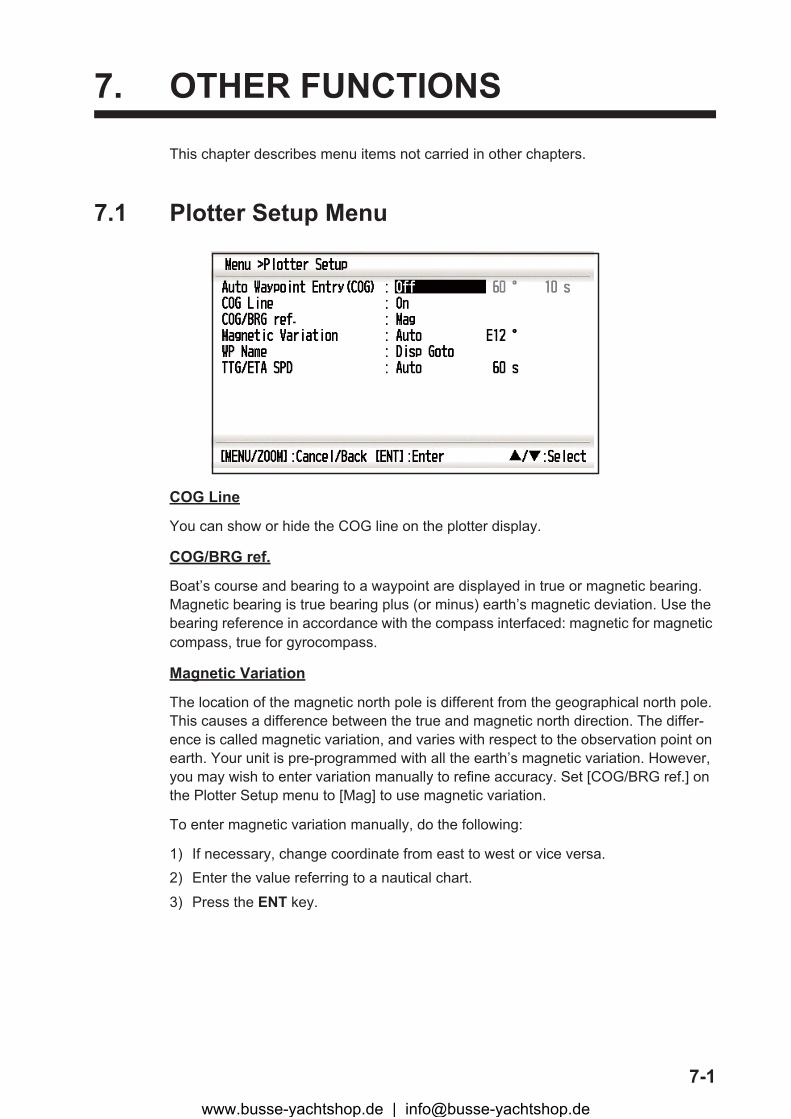
This chapter describes menu items not carried in other chapters.
7.1 Plotter Setup Menu
COG Line
You can show or hide the COG line on the plotter display.
COG/BRG ref.
Boat’s course and bearing to a waypoint are displayed in true or magnetic bearing. Magnetic bearing is true bearing plus (or minus) earth’s magnetic deviation. Use the bearing reference in accordance with the compass interfaced: magnetic for magnetic compass, true for gyrocompass.
Magnetic Variation
The location of the magnetic north pole is different from the geographical north pole. This causes a difference between the true and magnetic north direction. The differ-ence is called magnetic variation, and varies with respect to the observation point on earth. Your unit is pre-programmed with all the earth’s magnetic variation. However, you may wish to enter variation manually to refine accuracy. Set [COG/BRG ref.] on the Plotter Setup menu to [Mag] to use magnetic variation.
To enter magnetic variation manually, do the following:
1) If necessary, change coordinate from east to west or vice versa.2) Enter the value referring to a nautical chart.
3) Press the ENT key.
www.busse-yachtshop.de | [email protected]

7. OTHER FUNCTIONS
7-2
TTG/ETA SPD
To calculate time to go and estimated time of arrival, enter your speed as below.
1. Select [TTG/ETA SPD], and press the ENT key.2. Select [Auto] or [Manual].
Auto: Automatic speed input (GPS calculated speed)Manual: Manual speed input (1 to 999 sec.)
3. Press the ENT key.4. Press � and ENT key in order.
5. For [Manual], enter speed, and press the ENT key.
7.2 GPS Setup MenuThe GPS Setup menu smooths position and course, averages speed, applies position offset, and deactivates unhealthy satellites.
Datum
Your unit is programmed to recognize most of the major chart systems of the world. Although the WGS-84 system, the GPS standard, is now widely used other categories of charts still exist. Select the chart system used, not the area where your boat is sail-ing. Select WGS84 (default setting), WGS72 or Other (required the chart number en-tering).
Navigation
When you set a destination, the equipment displays the range, bearing and course to that destination. Range and bearing are circulated by the Great Circle or Rhumb Line method. Route total distance is also calculated. Cross-track error is only calculated in the Great Circle method.
Rhumb line: This method calculates the range and bearing between two points drawn on a nautical chart. Since the bearing is kept constant it is ideal for short-range navi-gation.
Great circle: This course line is the shortest course between two points on the surface of the earth, like stretching a piece of string between two points on earth. Because fre-quent course changes are required it is most suitable for long-range navigation.
www.busse-yachtshop.de | [email protected]
7. OTHER FUNCTIONS
7-3
Smooth Position
When the receiving condition is unfavorable, the GPS fix may change greatly, even if the boat is dead in water. This change can be reduced by smoothing the raw GPS fix-es. The setting range is from 0 (no smoothing) to 999 seconds. The higher the setting the more smoothed the raw data, however too high a setting slows response time to change in latitude and longitude. This is especially noticeable at high boat speeds. “0” is the normal setting; increase the setting if the GPS fix changes greatly.
Smooth S/C (speed/course)
During position fixing, your boat’s velocity (speed and course) is directly measured by receiving GPS satellite signals. The raw velocity data may change randomly depend-ing on receiving conditions and other factors. You can reduce this random variation by increasing the smoothing. Like with latitude and longitude smoothing, the higher the speed and course smoothing the more smoothed the raw data. If the setting is too high, however, the response to speed and course change slows. The setting range is from 0 (no smoothing) to 9999 seconds.
Lat Offset, Lon Offset
You may apply an offset to latitude and longitude position generated by the GPS re-ceiver, to increase position accuracy.
Disable SV (satellite)
Every GPS satellite is broadcasting abnormal satellite number(s) in its Almanac, which contains general orbital data about all GPS satellites. Using this information, the GPS receiver automatically eliminates any malfunctioning satellite from the GPS sat-ellite schedule. However, the Almanac sometimes may not contain this information. You can disable an inoperative satellite manually. Enter satellite numbers (max. three satellites) in two digits.
SV ELV (satellite elevator)
Set the orbit interval on the satellite monitor display.
www.busse-yachtshop.de | [email protected]
7. OTHER FUNCTIONS
7-4
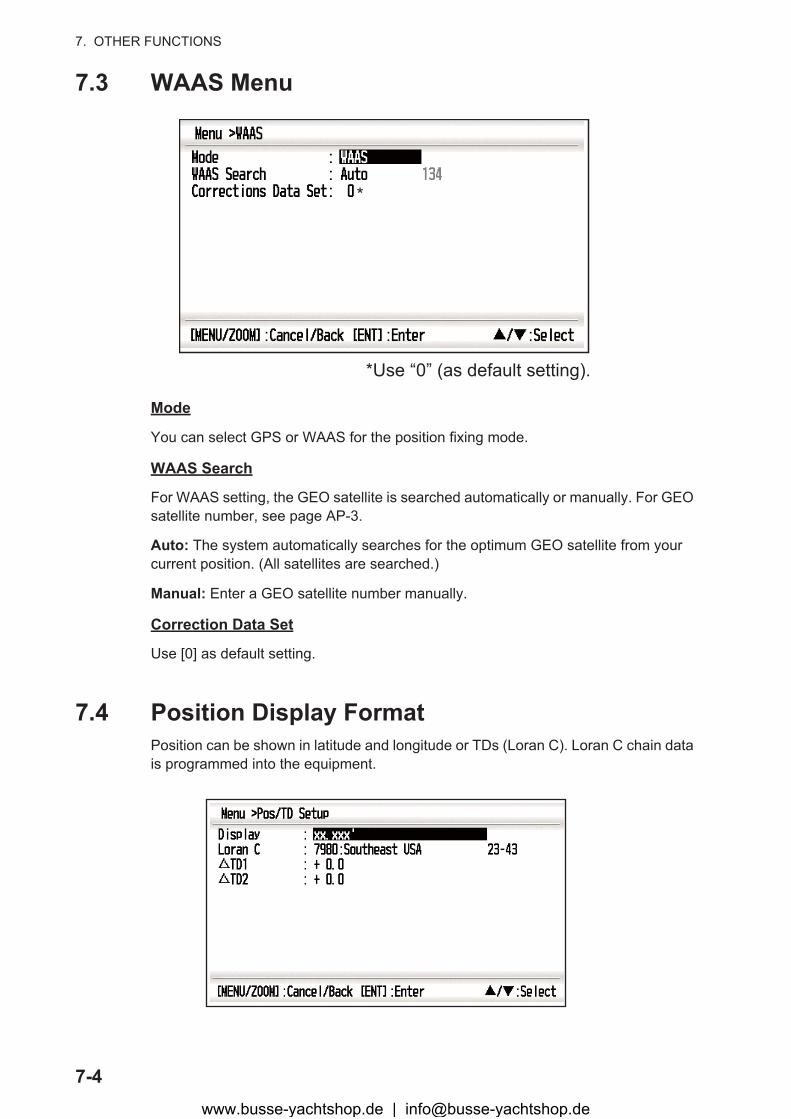
7.3 WAAS Menu
Mode
You can select GPS or WAAS for the position fixing mode.
WAAS Search
For WAAS setting, the GEO satellite is searched automatically or manually. For GEO satellite number, see page AP-3.
Auto: The system automatically searches for the optimum GEO satellite from your current position. (All satellites are searched.)
Manual: Enter a GEO satellite number manually.
Correction Data Set
Use [0] as default setting.
7.4 Position Display FormatPosition can be shown in latitude and longitude or TDs (Loran C). Loran C chain data is programmed into the equipment.
*Use “0” (as default setting).
*
www.busse-yachtshop.de | [email protected]

7. OTHER FUNCTIONS
7-5
Display
Select the position format.
• xx.xxx’: Shows L/L position with no seconds.• xx’xx.x”: Displays L/L position with seconds.• LC TD: Loran C TDs
Loran C
When choosing LC TD at Display, do the following:
1) Press the ENT key.2) select the GRI code, and press the ENT key.3) Press � and ENT key.4) Select secondary codes, and press the ENT key.
�TD1, �TD2
Enter TD offsets to refine Loran C position accuracy.
7.5 System MenuIn the System menu, you can customize various display settings, for example, time and date formats, etc.
Key Beep
This item turns the key beep on or off.
Units
The Units item lets you select the unit of measurement for range, speed and distance, from the units shown below.
www.busse-yachtshop.de | [email protected]
7. OTHER FUNCTIONS
7-6
Time Offset
GPS uses UTC time. If you would rather use local time, enter the time difference (range: -14:00 to +14:00, 15 minutes step) between it and UTC time.
Daylight Saving Time
For countries that use daylight savings time, select On to enable daylight savings time.
Time Display
You can display the time in 12 or 24 hour format.
Date Display
Select the date display, DD/MMM/YY or MM/DD/YY.
Demo
The demonstration display provides simulated operation of this unit. You may set the speed manually and course manually or automatically. All controls are operative - you may enter marks, set destination, etc.
• Mode: select [On]. The indication SIM appears at the top left-hand side to inform you that the simulation mode in use. To cancel, select [Off].
• Speed: Enter the speed (two digits) to use for the demonstration mode.• Course: Select Auto or Manual. For manual entry of course, enter course in three
digits. The Auto course tracks a circular course.
• Lat, Lon: Enter latitude and longitude of the position to start the demonstration.
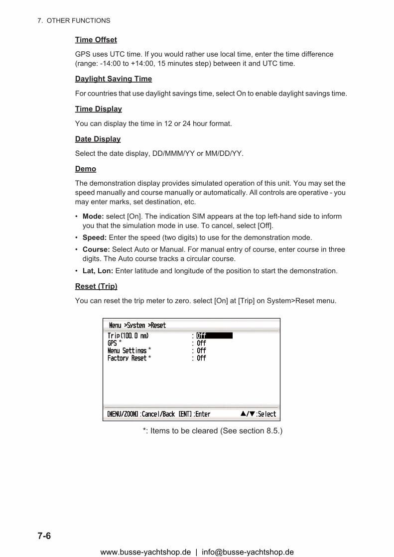
Reset (Trip)
You can reset the trip meter to zero. select [On] at [Trip] on System>Reset menu.
***
*: Items to be cleared (See section 8.5.)
www.busse-yachtshop.de | [email protected]
7. OTHER FUNCTIONS
7-7
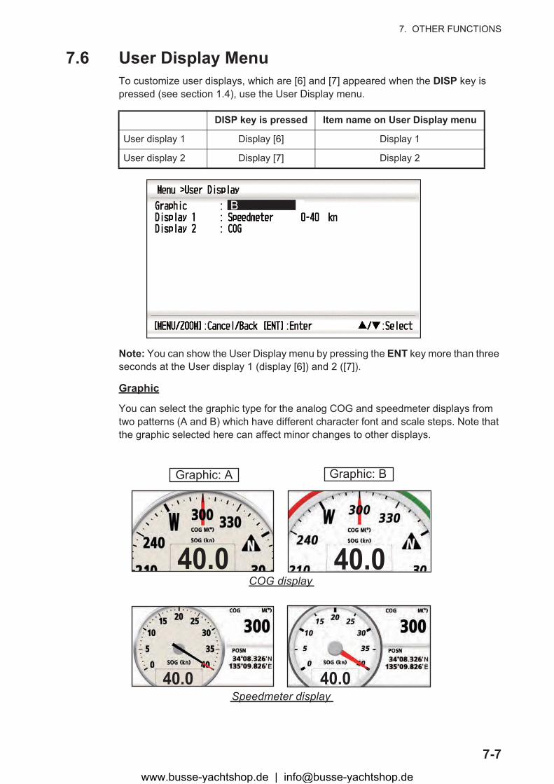
7.6 User Display MenuTo customize user displays, which are [6] and [7] appeared when the DISP key is pressed (see section 1.4), use the User Display menu.
Note: You can show the User Display menu by pressing the ENT key more than three seconds at the User display 1 (display [6]) and 2 ([7]).
Graphic
You can select the graphic type for the analog COG and speedmeter displays from two patterns (A and B) which have different character font and scale steps. Note that the graphic selected here can affect minor changes to other displays.
DISP key is pressed Item name on User Display menu
User display 1 Display [6] Display 1
User display 2 Display [7] Display 2
B
Graphic: A Graphic: B
COG display
Speedmeter display
40.040.0
40.0NE
40.0NE
www.busse-yachtshop.de | [email protected]
7. OTHER FUNCTIONS
7-8
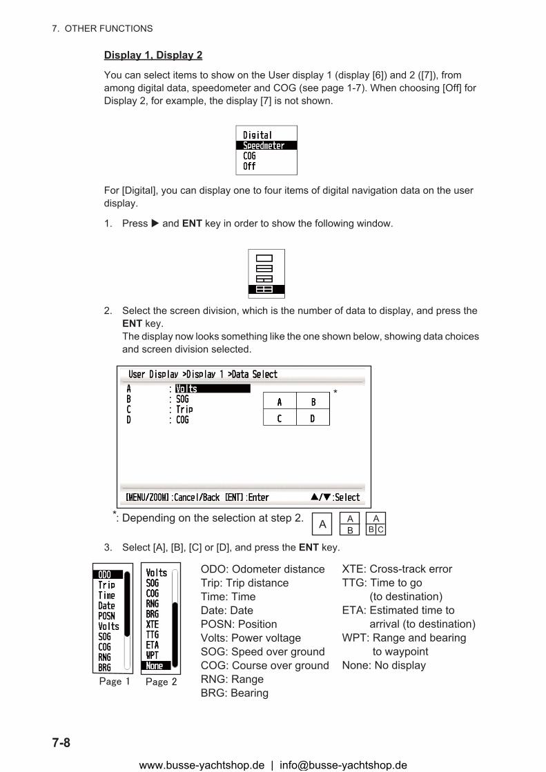
Display 1, Display 2
You can select items to show on the User display 1 (display [6]) and 2 ([7]), from among digital data, speedometer and COG (see page 1-7). When choosing [Off] for Display 2, for example, the display [7] is not shown.
For [Digital], you can display one to four items of digital navigation data on the user display.
1. Press � and ENT key in order to show the following window.
2. Select the screen division, which is the number of data to display, and press the ENT key.The display now looks something like the one shown below, showing data choices and screen division selected.
3. Select [A], [B], [C] or [D], and press the ENT key.
*
*: Depending on the selection at step 2. A AB
AB C
ODO: Odometer distanceTrip: Trip distanceTime: TimeDate: DatePOSN: PositionVolts: Power voltageSOG: Speed over groundCOG: Course over groundRNG: RangeBRG: Bearing
XTE: Cross-track errorTTG: Time to go (to destination)ETA: Estimated time to arrival (to destination)WPT: Range and bearing to waypointNone: No display
www.busse-yachtshop.de | [email protected]

7. OTHER FUNCTIONS
7-9
4. Select data desired, and press the ENT key.5. Repeat steps 3 and 4 to set other data.
You can select digital data also from the User display 1 (display [6]) and 2 ([7]) directly.
1. Press the DISP key several times to show User display 1 or 2 desired, and press the ENT key to show the cursor.
2. Operate the cursorpad to select the column to select data, and press the ENT key.
3. Select the item to show, and press the ENT key.4. Repeat steps 2 and 3 for other displays if necessary.
SpeedometerWhen choosing [speedometer], you can select the range for the spedmeter to show on the User display 1 or 2.
15.8Cursor (displayed approx. seven seconds)
23.9Volts (V) SOG (kn)
300COG M( )
100.0Trip (nm)
ODO: Odometer distanceTrip: Trip distanceTime: TimeDate: DatePOSN: PositionVolts: Power voltageSOG: Speed over groundCOG: Course over groundRNG: RangeBRG: Bearing
XTE: Cross-track errorTTG: Time to go (to destination)ETA: Estimated time to arrival (to destination)WPT: Range and bearing to waypointNone: No display
www.busse-yachtshop.de | [email protected]

7. OTHER FUNCTIONS
7-10
7.7 I/O Setup MenuWaypoint and route data can be uploaded from your unit to a PC, or downloaded from a PC to your unit.
There are two kinds of data for route data: route data and route comment data.
Note: No position fix is available during uploading or downloading.
Setting for communication software on PC
Baud Rate 38400 bps
Character Length 8 bit
Parity None
Stop Bit 1 bit
Flow Control XON/OFF
**
*
*
*: See chapter 9.
www.busse-yachtshop.de | [email protected]

7. OTHER FUNCTIONS
7-11
Waypoint data format
$PFEC, GPwpl, llll.ll, a, yyyyy.yy, a, c—c, c, c—c, a, hhmmss, xx, xx, xxxx <CR><LF> 1 2 3 4 5 6 7 8 9 10 11 12
1: Waypoint latitude
2: N/S
3: Waypoint longitude
4: E/W
5: Waypoint name (1 to 8 characters)
6: Waypoint color
(NULL/0: black, 1: red, 2: yellow, 3: green, 4: brown, 5: purple, 6: blue)
7: Waypoint comment (”@_ (see below.)” + 0 to 13 characters)
8: Flag marking waypoint (A: displayed, V: Not displayed)
9: UTC (Always NULL)
10: Day (Always NULL)
11: Month (Always NULL)
12: Year (Always NULL)
0x10: @q, 0x11: @r, 0x12: @s:, 0x13: @t, 0x14: @u,
0x15: @v, 0x16: @w, 0x17: @x, 0x18: @y, 0x19: @z
-Internal mark code is 0x10 through 0x19. 0x71 through 0x7A are always place at 2nd byte of mark code.-Following characters can be used for comments:
_ABCDEFGHIJKLMNOPQRSTUVWXYZ0123456789&()+-/=?> (space)
www.busse-yachtshop.de | [email protected]
7. OTHER FUNCTIONS
7-12
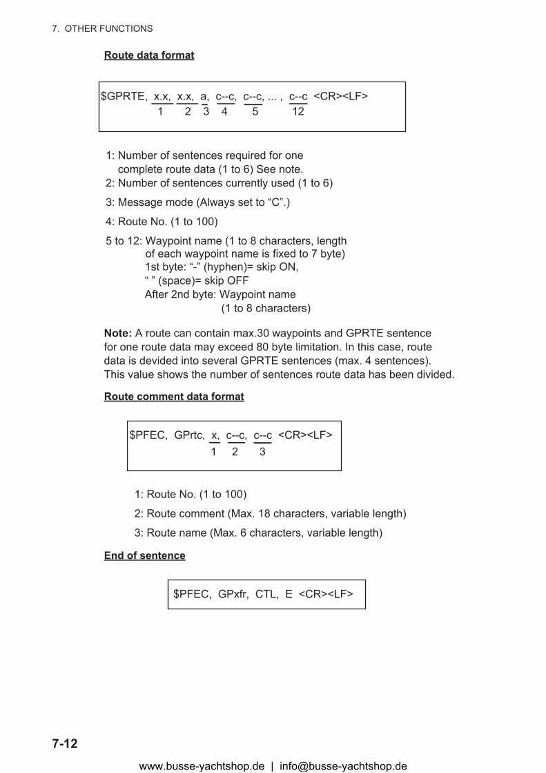
Route data format
Route comment data format
End of sentence
$GPRTE, x.x, x.x, a, c--c, c--c, ... , c--c <CR><LF> 1 2 3 4 5 12
1: Number of sentences required for one complete route data (1 to 6) See note.2: Number of sentences currently used (1 to 6)
3: Message mode (Always set to “C”.)
4: Route No. (1 to 100)
5 to 12: Waypoint name (1 to 8 characters, length of each waypoint name is fixed to 7 byte)
1st byte: “-” (hyphen)= skip ON,“ ” (space)= skip OFFAfter 2nd byte: Waypoint name (1 to 8 characters)
Note: A route can contain max.30 waypoints and GPRTE sentence for one route data may exceed 80 byte limitation. In this case, route data is devided into several GPRTE sentences (max. 4 sentences). This value shows the number of sentences route data has been divided.
$PFEC, GPrtc, x, c--c, c--c <CR><LF> 1 2 3
1: Route No. (1 to 100)
2: Route comment (Max. 18 characters, variable length)
3: Route name (Max. 6 characters, variable length)
$PFEC, GPxfr, CTL, E <CR><LF>
www.busse-yachtshop.de | [email protected]
7. OTHER FUNCTIONS
7-13
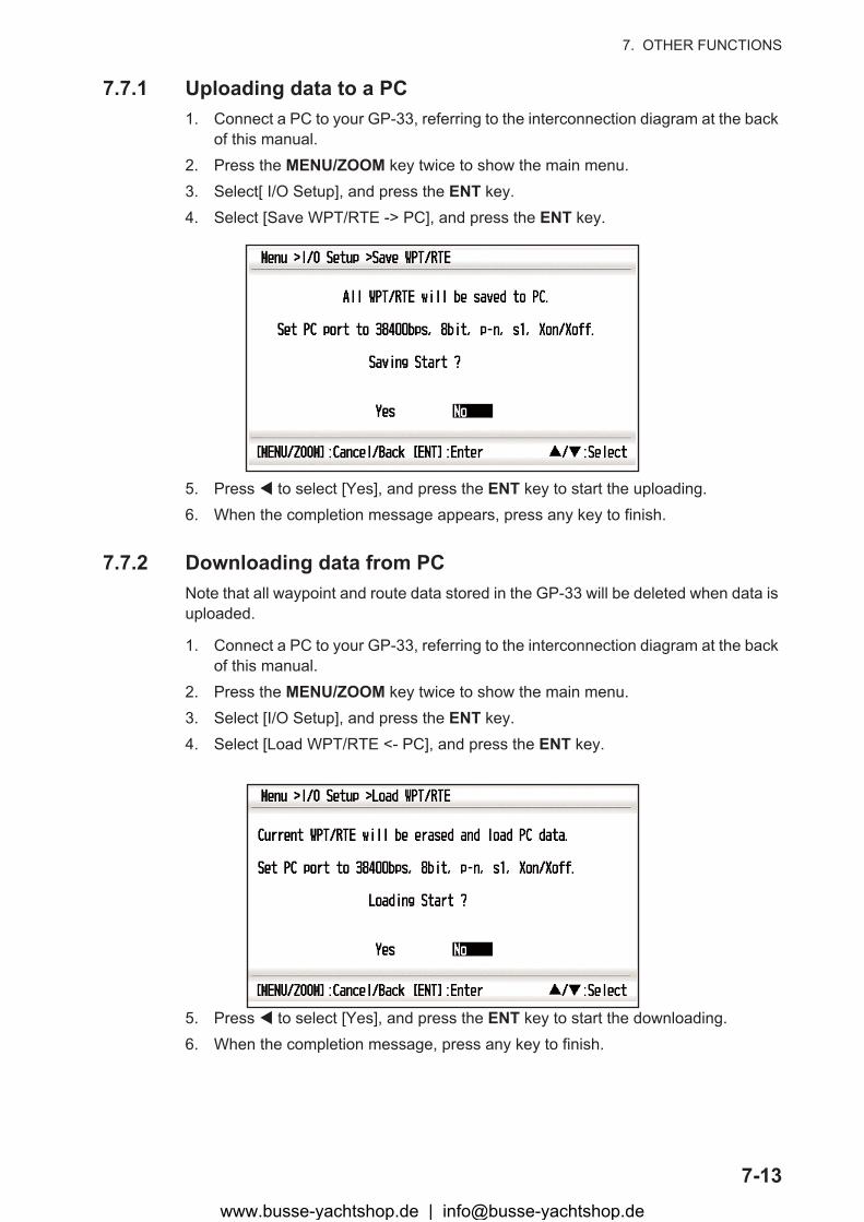
7.7.1 Uploading data to a PC1. Connect a PC to your GP-33, referring to the interconnection diagram at the back
of this manual.2. Press the MENU/ZOOM key twice to show the main menu.3. Select[ I/O Setup], and press the ENT key.4. Select [Save WPT/RTE -> PC], and press the ENT key.
5. Press � to select [Yes], and press the ENT key to start the uploading.6. When the completion message appears, press any key to finish.
7.7.2 Downloading data from PCNote that all waypoint and route data stored in the GP-33 will be deleted when data is uploaded.
1. Connect a PC to your GP-33, referring to the interconnection diagram at the back of this manual.
2. Press the MENU/ZOOM key twice to show the main menu.3. Select [I/O Setup], and press the ENT key.4. Select [Load WPT/RTE <- PC], and press the ENT key.
5. Press � to select [Yes], and press the ENT key to start the downloading.6. When the completion message, press any key to finish.
www.busse-yachtshop.de | [email protected]

7. OTHER FUNCTIONS
7-14
This page is intentionally left blank.
www.busse-yachtshop.de | [email protected]

8-1
8. MAINTENANCE, TROUBLE-SHOOTING
8.1 MaintenanceRegular maintenance is important to maintain performance. Check the following points to help maintain performance.
• Check that connectors on the rear panel are firmly tightened and free of rust.• Check that the ground system is free of rust and the ground wire is tightly fastened.• Check that battery terminals are clean and free of rust.• Dust or dirt may be removed from the cabinet with soft cloth. Water-diluted mild de-
tergent may be used if desired. DO NOT use chemical cleaners to clean the display unit; they may remove paint and markings.
• Wipe the LCD carefully to prevent scratching, using tissue paper and an LCD clean-er. To remove dirt or salt deposits, use an LCD cleaner, wiping slowly with tissue paper so as to dis-solve the dirt or salt. Change paper frequency so the salt or dirt will not scratch the LCD. Do not use solvents such as thinner, acetone or benzene for cleaning. Also, do not use degreaser or antifog solution, as they can strip the coating from the LCD.
Life of LCD
The life of the LCD is approximately 50,000 hours. The actual number of hours de-pends on ambient temperature and humidity. When the brilliance cannot be raised suf-ficiently, ask your dealer about replacement.
NOTICEDo not apply paint, anti-corrosivesealant or contact spray to plasticparts or equipment coating.
Those items contain products that candamage plastic parts and equipmentcoating.
www.busse-yachtshop.de | [email protected]
8. MAINTENANCE, TROUBLESHOOTING
8-2
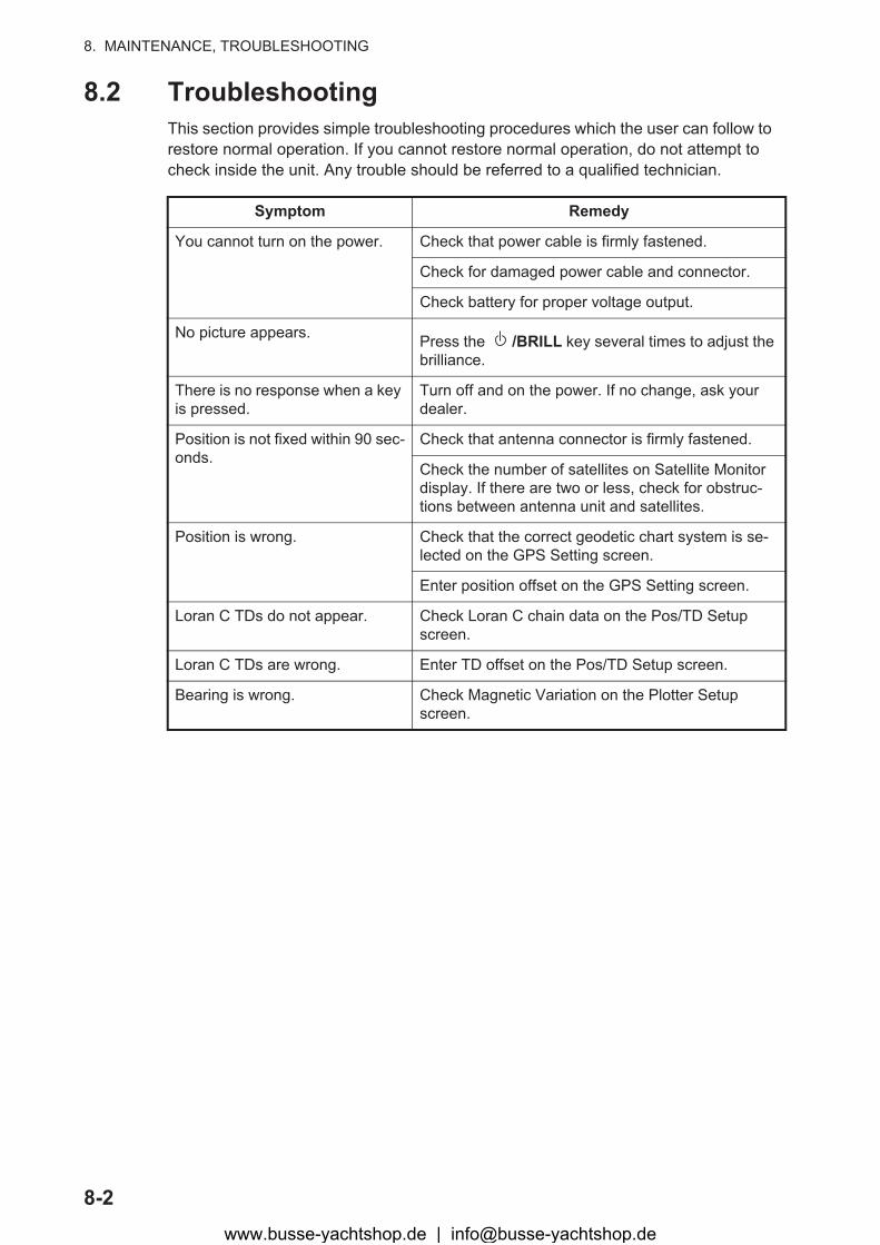
8.2 TroubleshootingThis section provides simple troubleshooting procedures which the user can follow to restore normal operation. If you cannot restore normal operation, do not attempt to check inside the unit. Any trouble should be referred to a qualified technician.
Symptom Remedy
You cannot turn on the power. Check that power cable is firmly fastened.
Check for damaged power cable and connector.
Check battery for proper voltage output.
No picture appears. Press the /BRILL key several times to adjust the brilliance.
There is no response when a key is pressed.
Turn off and on the power. If no change, ask your dealer.
Position is not fixed within 90 sec-onds.
Check that antenna connector is firmly fastened.
Check the number of satellites on Satellite Monitor display. If there are two or less, check for obstruc-tions between antenna unit and satellites.
Position is wrong. Check that the correct geodetic chart system is se-lected on the GPS Setting screen.
Enter position offset on the GPS Setting screen.
Loran C TDs do not appear. Check Loran C chain data on the Pos/TD Setup screen.
Loran C TDs are wrong. Enter TD offset on the Pos/TD Setup screen.
Bearing is wrong. Check Magnetic Variation on the Plotter Setup screen.
www.busse-yachtshop.de | [email protected]
8. MAINTENANCE, TROUBLESHOOTING
8-3
8.3 Displaying the Message BoardWhen an error occurs, a message and an alarm icon appear on the screen. The mes-sage board displays the error messages (see page 6-2) shown in table below.
Messages and meanings
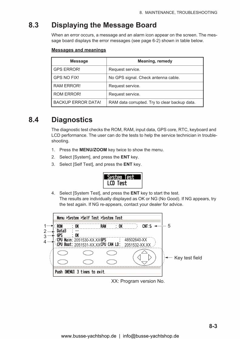
8.4 DiagnosticsThe diagnostic test checks the ROM, RAM, input data, GPS core, RTC, keyboard and LCD performance. The user can do the tests to help the service technician in trouble-shooting.
1. Press the MENU/ZOOM key twice to show the menu.2. Select [System], and press the ENT key.3. Select [Self Test], and press the ENT key.
4. Select [System Test], and press the ENT key to start the test.The results are individually displayed as OK or NG (No Good). If NG appears, try the test again. If NG re-appears, contact your dealer for advice.
Message Meaning, remedy
GPS ERROR! Request service.
GPS NO FIX! No GPS signal. Check antenna cable.
RAM ERROR! Request service.
ROM ERROR! Request service.
BACKUP ERROR DATA! RAM data corrupted. Try to clear backup data.
XX: Program version No.
123
2051530-XX.XX2051531-XX.XX 2051532-XX.XX
48502640-XX4
Key test field
5
www.busse-yachtshop.de | [email protected]
8. MAINTENANCE, TROUBLESHOOTING
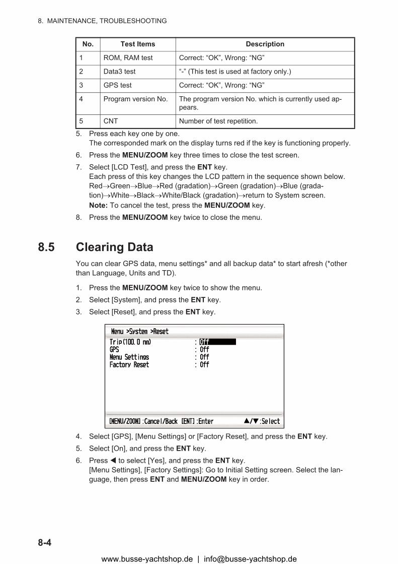
8-4
5. Press each key one by one.The corresponded mark on the display turns red if the key is functioning properly.
6. Press the MENU/ZOOM key three times to close the test screen.7. Select [LCD Test], and press the ENT key.
Each press of this key changes the LCD pattern in the sequence shown below.Red�Green�Blue�Red (gradation)�Green (gradation)�Blue (grada-tion)�White�Black�White/Black (gradation)�return to System screen.Note: To cancel the test, press the MENU/ZOOM key.
8. Press the MENU/ZOOM key twice to close the menu.
8.5 Clearing DataYou can clear GPS data, menu settings* and all backup data* to start afresh (*other than Language, Units and TD).
1. Press the MENU/ZOOM key twice to show the menu.2. Select [System], and press the ENT key.3. Select [Reset], and press the ENT key.
4. Select [GPS], [Menu Settings] or [Factory Reset], and press the ENT key.5. Select [On], and press the ENT key.6. Press � to select [Yes], and press the ENT key.
[Menu Settings], [Factory Settings]: Go to Initial Setting screen. Select the lan-guage, then press ENT and MENU/ZOOM key in order.
No. Test Items Description
1 ROM, RAM test Correct: “OK”, Wrong: “NG”
2 Data3 test “-” (This test is used at factory only.)
3 GPS test Correct: “OK”, Wrong: “NG”
4 Program version No. The program version No. which is currently used ap-pears.
5 CNT Number of test repetition.
www.busse-yachtshop.de | [email protected]

9-1
9. INSTALLATION
9.1 Equipment ListsStandard Supply
Optional Supply
9.2 Installation of Receiver Unit
9.2.1 Installation considerationThe receiver unit can be installed on a desktop, underside of table or in a panel. Refer to the outline drawings at the end of this manual for installation instructions. When se-lecting a mounting a location, keep in mind the following points:
• Locate the unit away from exhaust pipes and vents.• The mounting location should be well ventilated.• Mount the unit where shock and vibration are minimal.
Name Type Code No. Qty Remarks
Receiver unit GP-33 - 1
Antenna Unit GPA-017 - 1 w/10 m cable
Installation Materials CP20-03300 - 1 set -M12-05BM+05BF-060-CP20-03310
Accessories FP20-01200 - 1 set See the packing list at the back of this manual.
Name Type Qty Remarks
Junction Box FI-5002 000-010-765
Cable Assy. KON-004-02M 001-090-910
Right Angle Antenna Base
NO.13-QA330 000-803-239 For mounting the an-tenna unit, select one.(See the installa-tion procedure at the back of this manual.)
L-type Antenna Base NO.13-QA310 000-803-240
Handrail Antenna Base
NO.13-RC5160 000-806-114
Mast Mounting Kit CP20-01111 004-365-780
NMEA Connector SS-050505-FMF-TS001
000-168-603-10 CAN bus distributor, micro style
NC-050505FMF-TS001
000-160-507-10 CAN bus distributor, mini style
www.busse-yachtshop.de | [email protected]
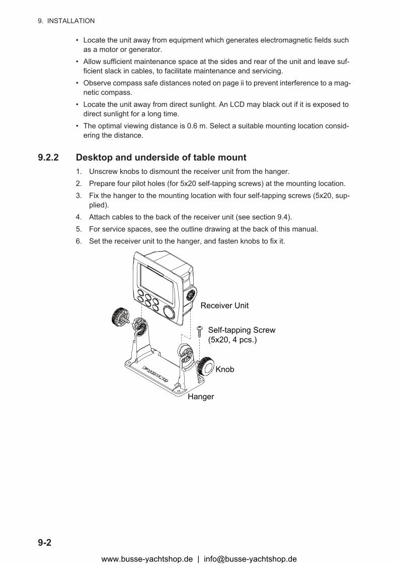
9. INSTALLATION
9-2
• Locate the unit away from equipment which generates electromagnetic fields such as a motor or generator.
• Allow sufficient maintenance space at the sides and rear of the unit and leave suf-ficient slack in cables, to facilitate maintenance and servicing.
• Observe compass safe distances noted on page ii to prevent interference to a mag-netic compass.
• Locate the unit away from direct sunlight. An LCD may black out if it is exposed to direct sunlight for a long time.
• The optimal viewing distance is 0.6 m. Select a suitable mounting location consid-ering the distance.
9.2.2 Desktop and underside of table mount1. Unscrew knobs to dismount the receiver unit from the hanger.2. Prepare four pilot holes (for 5x20 self-tapping screws) at the mounting location.3. Fix the hanger to the mounting location with four self-tapping screws (5x20, sup-
plied).4. Attach cables to the back of the receiver unit (see section 9.4).5. For service spaces, see the outline drawing at the back of this manual.6. Set the receiver unit to the hanger, and fasten knobs to fix it.
Self-tapping Screw(5x20, 4 pcs.)
Hanger
Knob
Receiver Unit
www.busse-yachtshop.de | [email protected]

9. INSTALLATION
9-3
9.2.3 Flush mount1. Using the template (supplied), cut out a hole in the mounting location.2. Prepare four pilot holes (for 3x20 self-tapping screws) at the mounting location.3. Unscrew knobs to dismount the receiver unit from the hanger.
This hanger can be discarded.4. Remove the front panel from the receiver unit by unfastening the catches at the
rear of the panel by hands, in the order shown in the figure below.
5. Attach the mount cushion (sponge) to the hole made at step 1, or receiver unit.6. Connect cables to the back of the receiver unit (see section 9.4).7. Use four self-tapping screws (3x20, supplied) to fasten the receiver unit to the
mounting location, and re-attach the front panel.
1
2
3
4
5
6
7
8
Mount cushion
(sponge)
Self-tapping Screw
(3x20, 4 pcs.)
Front Panel
Receiver
Unit
Mounting
Hole
www.busse-yachtshop.de | [email protected]

9. INSTALLATION
9-4
Note: When removing the equipment from the flush mounted location, use the remov-er (supplied) to remove the panel as shown below.
9.3 Installation of Antenna UnitInstall the antenna unit referring to the antenna installation diagram at the back of this manual. When choosing a mounting location for the antenna unit, keep in mind the fol-lowing points:
• Select a location out of the radar beam. The radar beam will obstruct or prevent re-ception of the GPS signal.
• The location should be well away from a VHF/UHF antenna. A GPS receiver is in-terfered by a harmonic wave of a VHF/UHF antenna.
• There should be no interfering object within the line-of-sight to the satellites. An ob-ject within line-of-sight to satellites, for example, a mast, may block reception or pro-long acquisition time.
• Mount the antenna unit as high as possible to keep it free from interfering objects and water spray. Freezing water can interrupt reception of the GPS satellite signal.
Note 1: Do not shorten the antenna cable.
Note 2: If the antenna cable is to be passed through a hole which is not large enough to pass the connector, unfasten the connector with a needle nose pliers and 3/8-inch open-end wrench. Refasten it as shown below, after running the cable through the hole.
1
2
Insert
Pull down
PinNut
Connector
Gasket (reddish-brown)Spring washer
Shield
www.busse-yachtshop.de | [email protected]
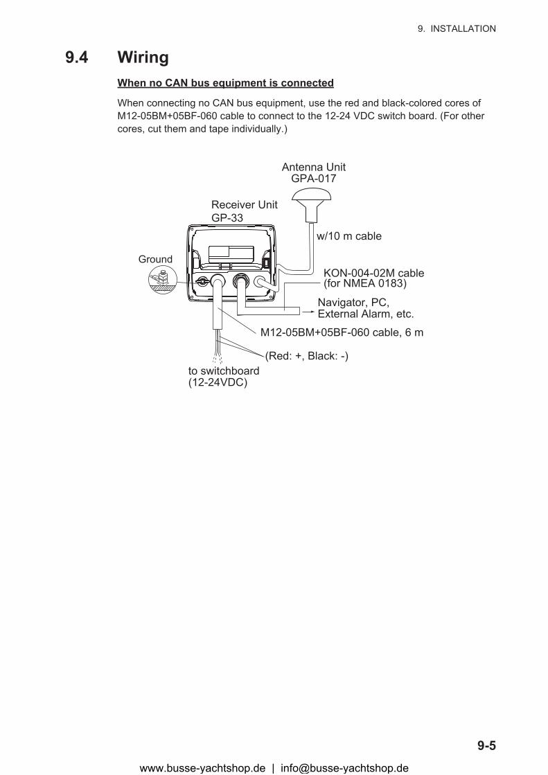
9. INSTALLATION
9-5
9.4 WiringWhen no CAN bus equipment is connected
When connecting no CAN bus equipment, use the red and black-colored cores of M12-05BM+05BF-060 cable to connect to the 12-24 VDC switch board. (For other cores, cut them and tape individually.)
Ground
Antenna UnitGPA-017
Receiver UnitGP-33
w/10 m cable
M12-05BM+05BF-060 cable, 6 m
Navigator, PC, External Alarm, etc.
KON-004-02M cable(for NMEA 0183)
(Red: +, Black: -)to switchboard(12-24VDC)
www.busse-yachtshop.de | [email protected]
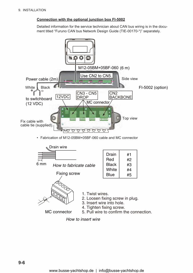
9. INSTALLATION
9-6
Connection with the optional junction box FI-5002
Detailed information for the service technician about CAN bus wiring is in the docu-ment titled “Furuno CAN bus Network Design Guide (TIE-00170-*)” separately.
• Fabrication of M12-05BM+05BF-060 cable and MC connector
12VDCCN3 - CN5DROP
FI-5002 (option)
Power cable (2m)
M12-05BM+05BF-060 (6 m)
to switchboard(12 VDC)
CN2BACKBONE
MC connector
White Black
Fix cable with cable tie (supplied).
Top view
Side viewUse CN2 to CN5.
MC connector
6 mm
1. Twist wires. 2. Loosen fixing screw in plug. 3. Insert wire into hole. 4. Tighten fixing screw. 5. Pull wire to confirm the connection.
#1#2#3#4#5
DrainRedBlackWhiteBlue
Drain wire
Fixing screw
How to fabricate cable
How to insert wire
www.busse-yachtshop.de | [email protected]
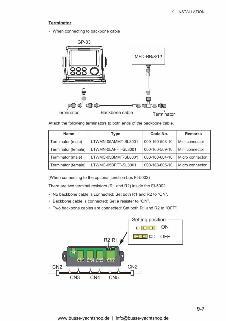
9. INSTALLATION
9-7
Terminator
• When connecting to backbone cable
Attach the following terminators to both ends of the backbone cable.
(When connecting to the optional junction box FI-5002)
There are two terminal resistors (R1 and R2) inside the FI-5002.
• No backbone cable is connected: Set both R1 and R2 to “ON”.• Backbone cable is connected: Set a resister to “ON”.• Two backbone cables are connected: Set both R1 and R2 to “OFF”.
Name Type Code No. Remarks
Terminator (male) LTWMN-05AMMT-SL8001 000-160-508-10 Mini connector
Terminator (female) LTWMN-05AFFT-SL8001 000-160-509-10 Mini connector
Terminator (male) LTWMC-05BMMT-SL8001 000-168-604-10 Micro connector
Terminator (female) LTWMC-05BFFT-SL8001 000-168-605-10 Micro connector
GP-33
Backbone cable
MFD-BB/8/12
Terminator Terminator
CN1CN3 CN4 CN5 CN2
R2 R1
CN3 CN4 CN5
CN2 CN2
: OFF
: ON
Setting position
www.busse-yachtshop.de | [email protected]
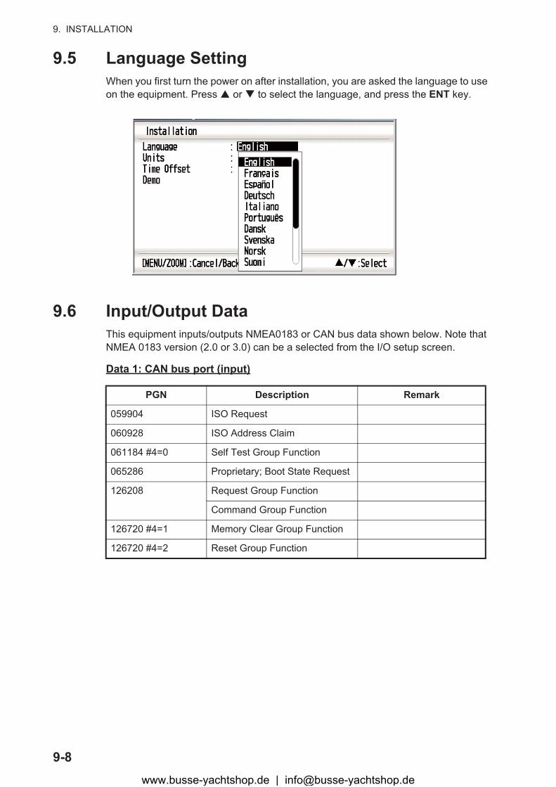
9. INSTALLATION
9-8
9.5 Language SettingWhen you first turn the power on after installation, you are asked the language to use on the equipment. Press � or � to select the language, and press the ENT key.
9.6 Input/Output DataThis equipment inputs/outputs NMEA0183 or CAN bus data shown below. Note that NMEA 0183 version (2.0 or 3.0) can be a selected from the I/O setup screen.
Data 1: CAN bus port (input)
PGN Description Remark
059904 ISO Request
060928 ISO Address Claim
061184 #4=0 Self Test Group Function
065286 Proprietary; Boot State Request
126208 Request Group Function
Command Group Function
126720 #4=1 Memory Clear Group Function
126720 #4=2 Reset Group Function
www.busse-yachtshop.de | [email protected]
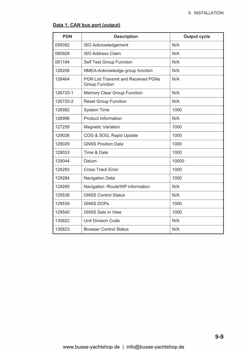
9. INSTALLATION
9-9
Data 1: CAN bus port (output)
PGN Description Output cycle
059392 ISO Acknowledgement N/A
060928 ISO Address Claim N/A
061184 Self Test Group Function N/A
126208 NMEA-Acknowledge group function N/A
126464 PGN List Transmit and Received PGNs Group Function
N/A
126720-1 Memory Clear Group Function N/A
126720-2 Reset Group Function N/A
126992 System Time 1000
126996 Product Information N/A
127258 Magnetic Variation 1000
129026 COG & SOG, Rapid Update 1000
129029 GNSS Position Data 1000
129033 Time & Date 1000
129044 Datum 10000
129283 Cross Track Error 1000
129284 Navigation Data 1000
129285 Navigation -Route/WP information N/A
129538 GNSS Control Status N/A
129539 GNSS DOPs 1000
129540 GNSS Sats in View 1000
130822 Unit Division Code N/A
130823 Browser Control Status N/A
www.busse-yachtshop.de | [email protected]
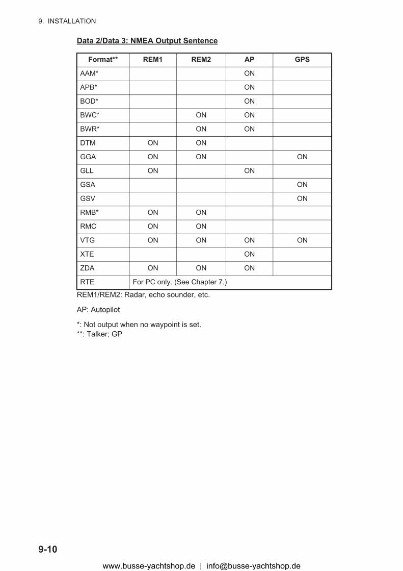
9. INSTALLATION
9-10
Data 2/Data 3: NMEA Output Sentence
REM1/REM2: Radar, echo sounder, etc.
AP: Autopilot
*: Not output when no waypoint is set.**: Talker; GP
Format** REM1 REM2 AP GPS
AAM* ON
APB* ON
BOD* ON
BWC* ON ON
BWR* ON ON
DTM ON ON
GGA ON ON ON
GLL ON ON
GSA ON
GSV ON
RMB* ON ON
RMC ON ON
VTG ON ON ON ON
XTE ON
ZDA ON ON ON
RTE For PC only. (See Chapter 7.)
www.busse-yachtshop.de | [email protected]
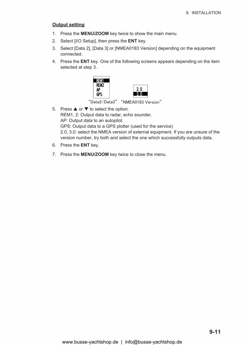
9. INSTALLATION
9-11
Output setting
1. Press the MENU/ZOOM key twice to show the main menu.2. Select [I/O Setup], then press the ENT key.3. Select [Data 2], [Data 3] or [NMEA0183 Version] depending on the equipment
connected.4. Press the ENT key. One of the following screens appears depending on the item
selected at step 3.
5. Press � or � to select the option.REM1, 2: Output data to radar, echo sounder.AP: Output data to an autopilot.GPS: Output data to a GPS plotter (used for the service)2.0, 3.0: select the NMEA version of external equipment. If you are unsure of the version number, try both and select the one which successfully outputs data.
6. Press the ENT key.
7. Press the MENU/ZOOM key twice to close the menu.
www.busse-yachtshop.de | [email protected]
9. INSTALLATION
9-12
This page is intentionally left blank.
www.busse-yachtshop.de | [email protected]
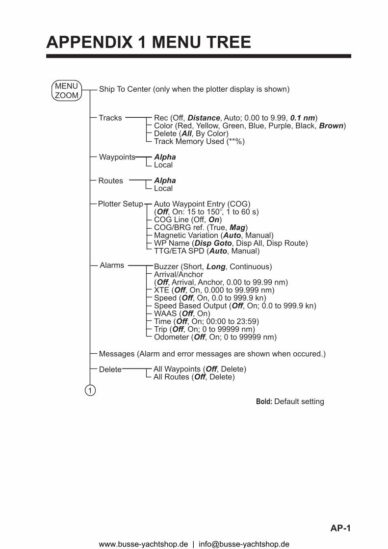
AP-1
APPENDIX 1 MENU TREE
Ship To Center (only when the plotter display is shown)
Tracks Rec (Off, Distance, Auto; 0.00 to 9.99, 0.1 nm)Color (Red, Yellow, Green, Blue, Purple, Black, Brown)Delete (All, By Color)Track Memory Used (**%)
AlphaLocal
AlphaLocal
Auto Waypoint Entry (COG) (Off, On: 15 to 150 , 1 to 60 s)COG Line (Off, On)COG/BRG ref. (True, Mag)Magnetic Variation (Auto, Manual)WP Name (Disp Goto, Disp All, Disp Route)TTG/ETA SPD (Auto, Manual)
Buzzer (Short, Long, Continuous)Arrival/Anchor(Off, Arrival, Anchor, 0.00 to 99.99 nm)XTE (Off, On, 0.000 to 99.999 nm)Speed (Off, On, 0.0 to 999.9 kn)Speed Based Output (Off, On; 0.0 to 999.9 kn)WAAS (Off, On)Time (Off, On; 00:00 to 23:59)Trip (Off, On; 0 to 99999 nm)Odometer (Off, On; 0 to 99999 nm)
Waypoints
Routes
Alarms
Messages (Alarm and error messages are shown when occured.)
Delete All Waypoints (Off, Delete)All Routes (Off, Delete)
MENUZOOM
1Bold: Default setting
Plotter Setup
www.busse-yachtshop.de | [email protected]

APPENDIX 1 MENU TREE
AP-2
I/O Setup
Pos/TD Setup
WAAS
GPS Setup Datum (WGS84, WGS72, Other; 003 to 173)Navigation (Rhumb Line, Great Circle)Smooth Position (0 to 999 s, 0 s)Smooth S/C (0 to 9999 s, 5 s)Lat Offset (0.000 N/S to 9.999 N/S, 0.000’ N)Lon Offset (0.000 E/W to 9.999 E/W, 0.000’E)Disable SVSV ELV (5 to 90 , 5 )
Mode (WAAS, GPS)WAAS Search (Auto, Manual; 120 to 138)Correction Data Set (0 to 27, 99; 0)
Data 2 (REM1, REM2, AP, GPS)Data 3 (REM1, REM2, AP, GPS)NMEA0183 Version (2.0, 3.0)Save WPT/RTE -> PCLoad WPT/RTE <- PCWiring Info. NMEA 0183Wiring Info. CAN bus Devices
Graphic (A, B)Display 1 (Digital, Speedometer, COG, Off; 0-20, 0-40, 0-80)Display 2 (Digital, Speedometer, COG, Off)
Display (xx.xxx', xx'xx.x", LC TD)Loran C (4990: Central Pacific, 11-29)TD1 (-99.9 to +99.9; +0.0)TD2 (-99.9 to +99.9; +0.0)
Key Beep (Off, On)Language (English, others)Units (nm-kn, km-km/h, sm-mph)Time Offset (-14:00 to +14:00; -8:00)Daylight Saving Time (Off, On)Time Display (12Hours, 24Hours)Date Display (DD/MMM/YY, MM/DD/YY)Demo Mode (Off, On) Speed (0 to 99 kn; 20 kn) Course (Auto, Manual; 0 to 359 ) Lat (N/S; 38 00’N) Lon (E/W; 123 00’W)Self Test (System Test, LCD Test)Reset Trip (0.00 nm) (Off, On) GPS (Off, On) Menu Settings (Off, On) Factory Reset (Off, On)
User Display
System
1
www.busse-yachtshop.de | [email protected]

AP-3
APPENDIX 2 WHAT IS WAAS?
WAAS, available in North America, is a provider in the worldwide SBAS (Satellite Based Augmen-tation System) navigation system. CBAS provides GPS signal corrections to SBAS users, for even better position accuracy, typically better than three meters. There are three more SBAS providers, MSAS (Multi-Functional Satellite Augmentation System) for Japan, EGNOS (Euro Geostationary Navigation Overlay Service) for Europe and GAGAN (GPS And GEO Augmented Navigation) for India. The illustration below shows the coverage area. (Accuracy may be affected when using a GEO satellite not within your current location.) This manual uses “WAAS” for these three providers generically.
Provider Satellite type Longitude Satellite No.
WAAS Intelsat Galaxy XV 133°W 135
TeleSat Anik F1R 107.3°W 138
EGNOS Inmarsat-3-F2/AOR-E 15.5°W 120
Artemis 21.5°E 124
Inmarsat-3-F5/IOR-W 25°E 126
MSAS MTSAT-1R 140°E 129
MTSAT-2 145°E 137
GAGAN Inmarsat-4-F1/IOR 64°E 127
WAAS
MSAS
EGNOS
GAGAN
www.busse-yachtshop.de | [email protected]
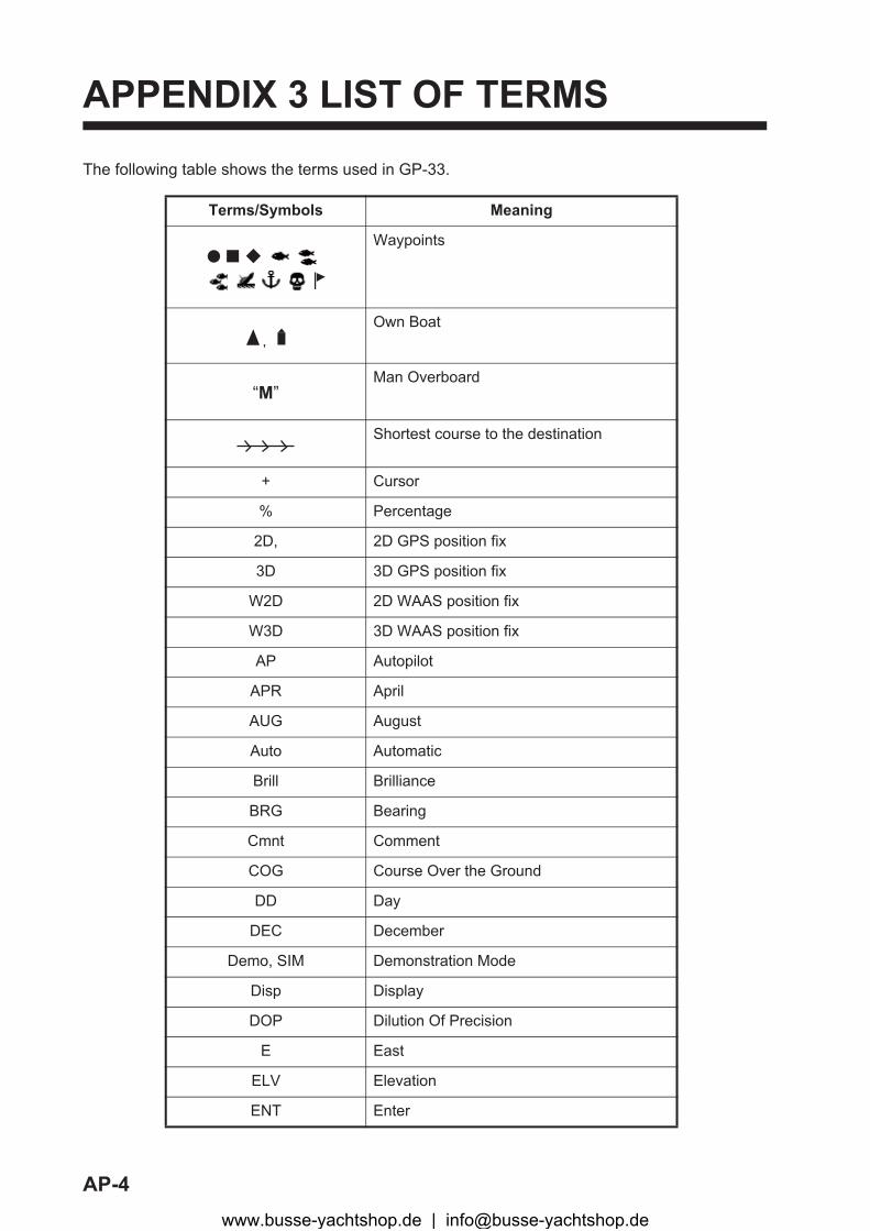
AP-4
APPENDIX 3 LIST OF TERMS
The following table shows the terms used in GP-33.
Terms/Symbols Meaning
Waypoints
Own Boat
Man Overboard
Shortest course to the destination
+ Cursor
% Percentage
2D, 2D GPS position fix
3D 3D GPS position fix
W2D 2D WAAS position fix
W3D 3D WAAS position fix
AP Autopilot
APR April
AUG August
Auto Automatic
Brill Brilliance
BRG Bearing
Cmnt Comment
COG Course Over the Ground
DD Day
DEC December
Demo, SIM Demonstration Mode
Disp Display
DOP Dilution Of Precision
E East
ELV Elevation
ENT Enter
“M”
www.busse-yachtshop.de | [email protected]
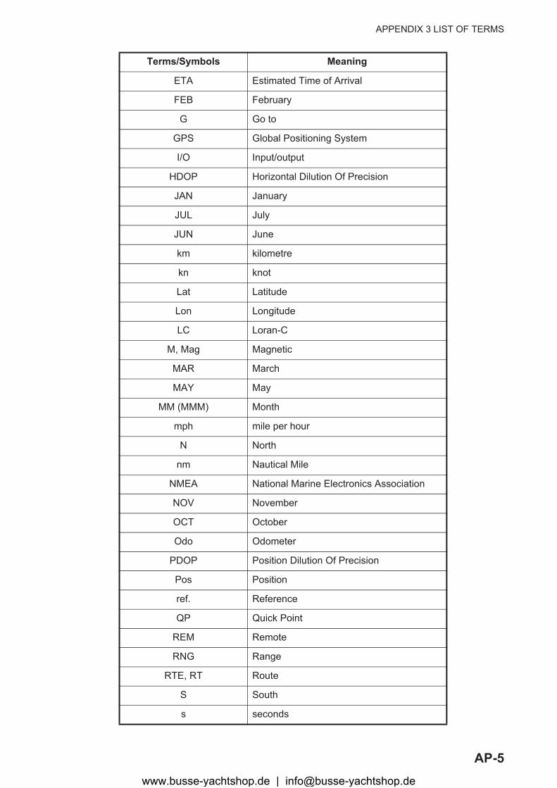
APPENDIX 3 LIST OF TERMS
AP-5
ETA Estimated Time of Arrival
FEB February
G Go to
GPS Global Positioning System
I/O Input/output
HDOP Horizontal Dilution Of Precision
JAN January
JUL July
JUN June
km kilometre
kn knot
Lat Latitude
Lon Longitude
LC Loran-C
M, Mag Magnetic
MAR March
MAY May
MM (MMM) Month
mph mile per hour
N North
nm Nautical Mile
NMEA National Marine Electronics Association
NOV November
OCT October
Odo Odometer
PDOP Position Dilution Of Precision
Pos Position
ref. Reference
QP Quick Point
REM Remote
RNG Range
RTE, RT Route
S South
s seconds
Terms/Symbols Meaning
www.busse-yachtshop.de | [email protected]

APPENDIX 3 LIST OF TERMS
AP-6
S/C Speed/Course
SEP September
sm Statute Mile
SOG Speed Over the Ground
SPD Speed
T True
TD Time Difference
TTG Time To Go
Volt Voltage
W West
WAAS Wide Area Augmentation System
WPT, WP Waypoint
XTE Cross Track Error
YY Year
Terms/Symbols Meaning
www.busse-yachtshop.de | [email protected]
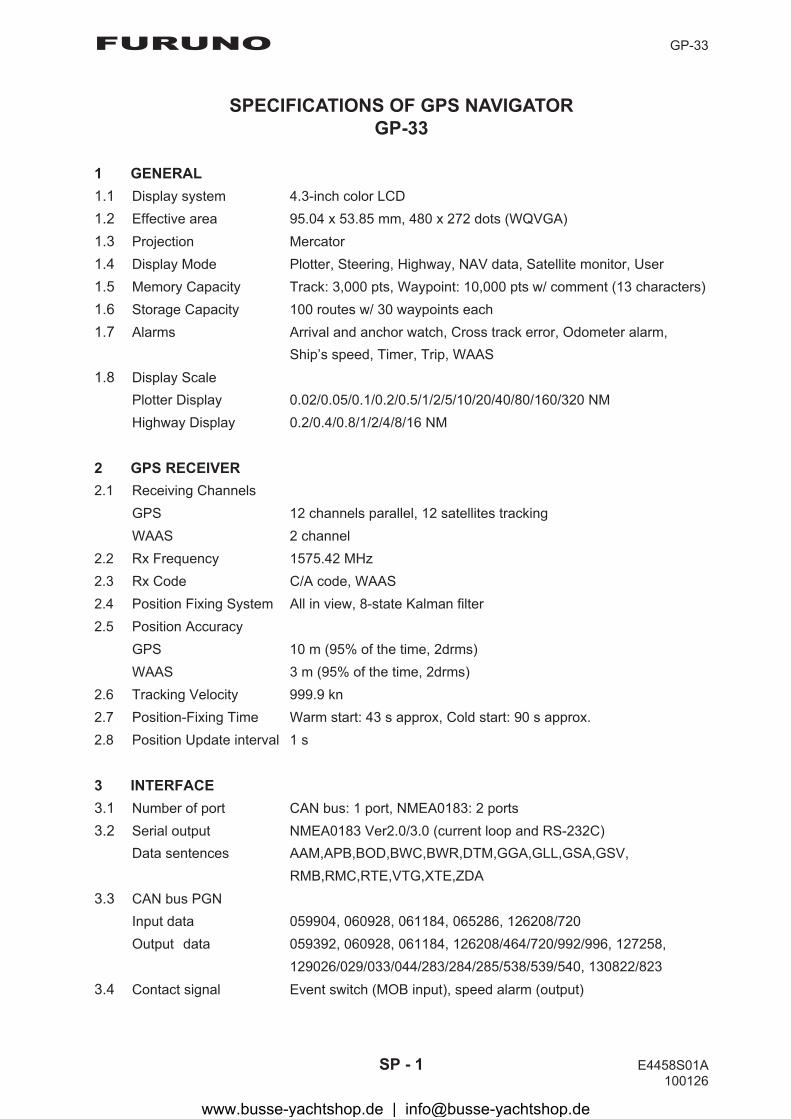
FURUNO GP-33
SP - 1 E4458S01A 100126
SPECIFICATIONS OF GPS NAVIGATOR GP-33
1 GENERAL 1.1 Display system 4.3-inch color LCD 1.2 Effective area 95.04 x 53.85 mm, 480 x 272 dots (WQVGA) 1.3 Projection Mercator 1.4 Display Mode Plotter, Steering, Highway, NAV data, Satellite monitor, User 1.5 Memory Capacity Track: 3,000 pts, Waypoint: 10,000 pts w/ comment (13 characters) 1.6 Storage Capacity 100 routes w/ 30 waypoints each 1.7 Alarms Arrival and anchor watch, Cross track error, Odometer alarm,
Ship’s speed, Timer, Trip, WAAS 1.8 Display Scale
Plotter Display 0.02/0.05/0.1/0.2/0.5/1/2/5/10/20/40/80/160/320 NM Highway Display 0.2/0.4/0.8/1/2/4/8/16 NM
2 GPS RECEIVER 2.1 Receiving Channels
GPS 12 channels parallel, 12 satellites tracking WAAS 2 channel
2.2 Rx Frequency 1575.42 MHz 2.3 Rx Code C/A code, WAAS 2.4 Position Fixing System All in view, 8-state Kalman filter 2.5 Position Accuracy
GPS 10 m (95% of the time, 2drms) WAAS 3 m (95% of the time, 2drms)
2.6 Tracking Velocity 999.9 kn 2.7 Position-Fixing Time Warm start: 43 s approx, Cold start: 90 s approx. 2.8 Position Update interval 1 s 3 INTERFACE 3.1 Number of port CAN bus: 1 port, NMEA0183: 2 ports 3.2 Serial output NMEA0183 Ver2.0/3.0 (current loop and RS-232C)
Data sentences AAM,APB,BOD,BWC,BWR,DTM,GGA,GLL,GSA,GSV, RMB,RMC,RTE,VTG,XTE,ZDA
3.3 CAN bus PGN Input data 059904, 060928, 061184, 065286, 126208/720 Output� data 059392, 060928, 061184, 126208/464/720/992/996, 127258, 129026/029/033/044/283/284/285/538/539/540, 130822/823
3.4 Contact signal Event switch (MOB input), speed alarm (output)
www.busse-yachtshop.de | [email protected]

FURUNO GP-33
SP - 2 E4458S01B
4 POWER SUPPLY 15VDC: LEN 7 (CAN bus) 12-24 VDC: 0.24-0.12 A (Non CAN bus) 5 ENVIRONMENTAL CONDITION 5.1 Ambient temperature
Antenna unit -25°C to +70°C Receiver unit -15°C to +55°C
5.2 Relative humidity 93% at 40°C 5.3 Degree of protection IP56 5.4 Vibration IEC 60945 6 UNIT COLOR 6.1 Antenna unit N9.5 6.2 Receiver unit N2.5
www.busse-yachtshop.de | [email protected]
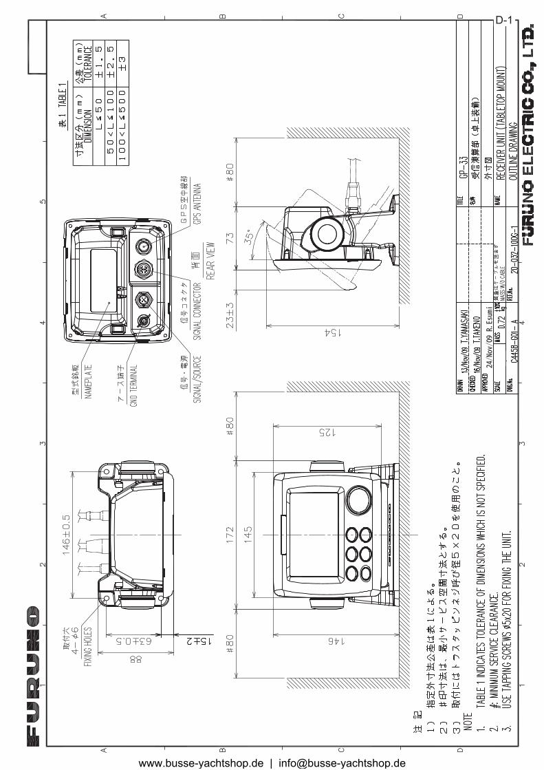
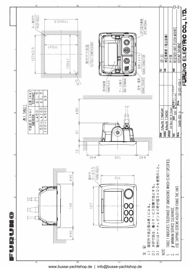
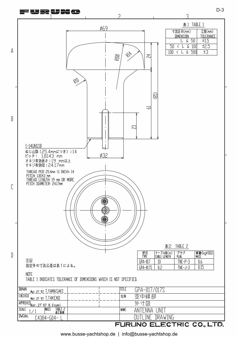
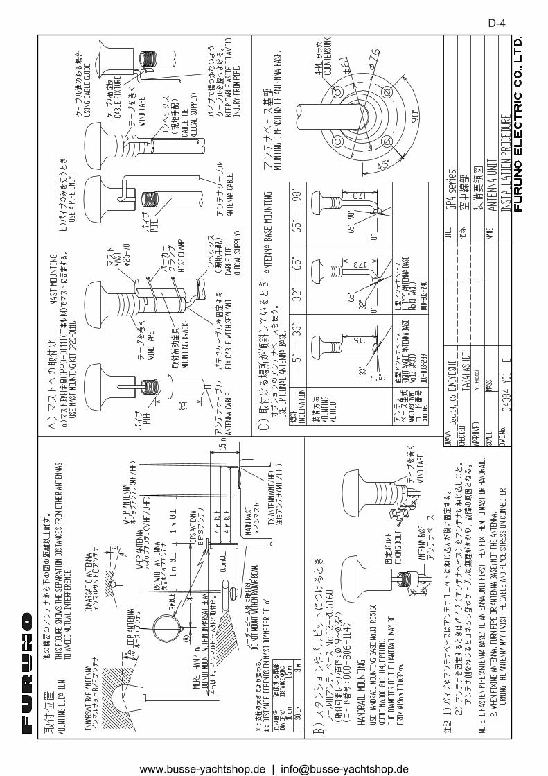

IN-1
INDEXAAlarm icon ..................................................6-1Alarm message ..........................................6-1alphanumeric data .....................................1-9Anchor watch alarm ...................................6-4Arrival alarm...............................................6-4
Bbuzzer ........................................................6-2Buzzer type ................................................6-2
CCAN bus......................................9-5, 9-8, 9-9Centering own boat’s position....................2-2COG Line ...................................................7-1COG/BRG ref. ............................................7-1Comment ...................................................3-2Correction Data Set ...................................7-4Cursorpad ..................................................1-1
DDate Display...............................................7-6Datum ........................................................7-2Daylight Saving Time .................................7-6Delete a waypoint from a route ..................4-3Demo .........................................................7-6diagnostic test ............................................8-3Disable SV (satellite)..................................7-3DISP key ....................................................1-1Display .......................................................7-5DOP ...........................................................1-2Downloading data from PC ......................7-13
EEdit waypoints on the plotter display..........3-5Edit waypoints through the list ...................3-5End of sentence .......................................7-12ENT key .....................................................1-1Enter a waypoint at own boat position .......3-1Enter a waypoint through the list................3-1Enter a waypoint with the cursor ................3-1Enter waypoints automatically ...................3-3Erase a route through the route list............4-5Erase a waypoint on the plotter display .....3-7Erase a waypoint through the waypoint list3-7Erase all routes ..........................................4-5Erase all waypoints ....................................3-8
GGO TO key.................................................1-1Graphic ......................................................7-7Great circle.................................................7-2
HHard cover .................................................1-2Highway Display ........................................1-5
IInsert a waypoint in a route ........................4-4
Jjunction box................................................9-6
KKey Beep ...................................................7-5
LLat Offset ...................................................7-3LCD brilliance.............................................1-3Life of LCD .................................................8-1Lon Offset ..................................................7-3Loran C ......................................................7-5
MMagnetic Variation .....................................7-1MENU/ZOOM key ......................................1-1MOB mark ..................................................1-9Mode ..........................................................7-4
NNav Data Display .......................................1-6Navigation ..................................................7-2NMEA............................................. 9-10, 9-11
OOdometer alarm .........................................6-5
PPanel brilliance...........................................1-3Plotter Display............................................1-4
RReplace a waypoint in a route....................4-3Reset (Trip) ................................................7-6Rhumb line.................................................7-2Route comment data format.....................7-12Route data format ....................................7-12
SSatellite Monitor Display.............................1-7Set destination by cursor position ..............5-1Set destination by waypoint .......................5-2Set route as destination .............................5-2Smooth Position.........................................7-3Smooth S/C (speed/course).......................7-3Speed alarm...............................................6-5Speed Based Output alarm........................6-5Speedmeter ...............................................7-9Steering Display.........................................1-6SV ELV (satellite elevator) .........................7-3
TTemporarily deselect a waypoint in a route4-4Terminator..................................................9-7Time alarm .................................................6-5Time Display ..............................................7-6
www.busse-yachtshop.de | [email protected]
INDEX
IN-2
Time Offset................................................ 7-6Track Color................................................ 2-4Track Memory Used.................................. 2-3Trip alarm .................................................. 6-5TTG/ETA SPD........................................... 7-2
UUnits .......................................................... 7-5Uploading data to a PC ........................... 7-13User Display.............................................. 1-7
WWAAS alarm.............................................. 6-5WAAS Search ........................................... 7-4Waypoint data format .............................. 7-11Waypoint Name......................................... 3-4WPT/MOB key .......................................... 1-1
XXTE (Cross Track Error) alarm ................. 6-5
www.busse-yachtshop.de | [email protected]
