guidelines for method of measurement of radioactive ... · pdf fileguidelines for method of...
TRANSCRIPT
1
Part V
Guidelines for Method of Measurement of Radioactive Concentration
(Tentative Translation)
March 2013, 2nd Edition
Table of Contents
Introduction ............................................................................................................................................................... 2
Chapter 1 Measuring Instruments ...................................................................................................................... 3
Chapter 2 Dose Rates in the Air ......................................................................................................................... 5
2.1 Measurement during Storage ...................................................................................................................... 5
2.2 Measurement during Transportation ......................................................................................................... 12
2.2.1 Measurement Method ...................................................................................................................... 12
2.2.2 Management of Measurement Results ............................................................................................. 14
2.3 Measurement at Incineration Facilities, Sludge Dehydration Facilities, etc. ............................................ 17
2.3.1 Measurement Method ...................................................................................................................... 17
2.3.2 Management of Measurement Results ............................................................................................. 19
2.4 Measurement at Landfill Site .................................................................................................................... 23
2.4.1 Measurement Method ...................................................................................................................... 23
2.4.2 Management of Measurement Results ............................................................................................. 25
Chapter 3 Discharged Gas ................................................................................................................................ 29
3.1 Specimen Sampling................................................................................................................................... 29
3.2 Management of Measurement Results ........................................................................................................ 31
3.3 Analysis Conditions and Lower Limit of Detection ................................................................................. 32
4.1 Specimen Sampling................................................................................................................................... 36
4.2 Management of Measurement Results ...................................................................................................... 37
4.3 Analysis Conditions and Lower Limit of Detection ................................................................................. 38
Chapter 5 Effluent and Water in Public Water Area ........................................................................................ 44
5.1 Specimen Sampling................................................................................................................................... 44
5.2 Management of Measurement Results ...................................................................................................... 44
5.3 Analysis Conditions and Lower Limit of Detection ................................................................................. 46
Chapter 6 Surrounding Groundwater ............................................................................................................... 52
6.1 Specimen Sampling................................................................................................................................... 52
6.2 Management of Measurement Results ...................................................................................................... 53
6.3 Analysis Conditions and Lower Limit of Detection ................................................................................. 53
Chapter 7 Burnt Residue, Soot and Dust, Discharged Sludge, Slag from Ash Melting Furnace, Fly Ash from
Ash Melting Furnace ......................................................................................................................... 57
7.1 Specimen Sampling................................................................................................................................... 57
7.2 Management of Measurement Results ...................................................................................................... 59
7.3 Analysis Conditions and Lower Limit of Detection ................................................................................. 59
Chapter 8 Elution Amount ............................................................................................................................... 63
8.1 Elution Amount Test Method ................................................................................................................... 64
8.2 Management of Measurement Results ...................................................................................................... 64
8.3 Analysis Conditions and Lower Limit of Detection ................................................................................. 65
Chapter 9 Cited Standards, etc. ........................................................................................................................ 68
2
Introduction
In the Guidelines, specific methods, etc., shall be explained for the measurement of the air dose rates and
radioactive concentrations provided for in Ordinance for Enforcement of the Act on Special Measures
concerning the Handling of Environment Pollution by Radioactive Materials Discharged by the Nuclear Power
Station Accident Associated with the Tohoku District - Off the Pacific Ocean Earthquake that Occurred on
March 11, 2011 (Ordinance of the Ministry of the Environment, No. 33 of 2011. (Hereinafter referred to as the
“Ordinance.”) )
The Guidelines are prepared on presumption that the person required to make measurements under the
Ordinance shall refer to these Guidelines together with each of the Guidelines from Part II through Part IV,
which explain method of treatment, etc., of waste.
For the summary and purpose, etc., of the standards for various measurements in the Ordinance, please
confirm in each of the Guidelines from Part II through Part IV.
3
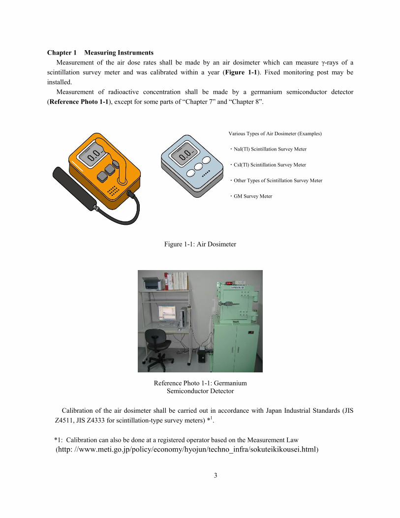
Chapter 1 Measuring Instruments
Measurement of the air dose rates shall be made by an air dosimeter which can measure γ-rays of a
scintillation survey meter and was calibrated within a year (Figure 1-1). Fixed monitoring post may be
installed.
Measurement of radioactive concentration shall be made by a germanium semiconductor detector
(Reference Photo 1-1), except for some parts of “Chapter 7” and “Chapter 8”.
Figure 1-1: Air Dosimeter
Reference Photo 1-1: Germanium
Semiconductor Detector
Calibration of the air dosimeter shall be carried out in accordance with Japan Industrial Standards (JIS
Z4511, JIS Z4333 for scintillation-type survey meters) *1.
*1: Calibration can also be done at a registered operator based on the Measurement Law
(http: //www.meti.go.jp/policy/economy/hyojun/techno_infra/sokuteikikousei.html)
Various Types of Air Dosimeter (Examples)
・NaI(Tl) Scintillation Survey Meter
・CsI(Tl) Scintillation Survey Meter
・Other Types of Scintillation Survey Meter
・GM Survey Meter
4
If the above-mentioned calibration cannot be carried out easily, five measurements at the same location
can be taken at the same time as a calibrated energy compensation scintillation survey meter serving as a
separate standard to verify that the target device satisfies the required performance. After verifying and
recording the ratio of the average standard value to the average of the measurements (average of the
standard values / average of the measured values), the correct measured value can be calculated by
multiplying the ratio by the actual measured value (however, when the ratio of the average measured value
with the standard calibrated measurement device varies by more than 20%*2 above or below 1, then that
measurement device is then deemed not to be sufficiently reliable).
In addition, when calibrating in a location with the same level of radioactivity as the region used in reality,
after verifying and recording the magnitude of the difference in the indicated value, the correct measured
value can also be calculated by adjusting the average difference from the actual measured value (however,
when the average of the difference in the measured value from the standard calibrated measurement device
varies by more than 20%*2, then that measurement device is then deemed not to be sufficiently reliable) .
*2: JIS Z 4333 The permissible range of the relative standard error is assumed to the ± (15+U) % or 20%
in “survey meters for measuring the dose equivalent ratio for X -ray and γ-ray” where U is
considered to be less than 5% due to the uncertainty of the reference dose.
5
Chapter 2 Dose Rates in the Air
Measurement of radiation levels prescribed by the Minister of the Environment
(Ministry of the Environment Bulletin No. 110 dated Dec 28, 2011)
Under the method prescribed by the Minister of the Environment under Article 15 item (xi) of the Special
Measures Act Enforcement Ordinance on the treatment of environmental contamination caused by
radioactive substances discharged by the nuclear plant accident as a result of the Pacific Ocean earthquake
which occurred in the Tohoku region on Mar 11, 2011, measurements shall be taken using a gamma ray
measurement device at a height of between 50 cm and 1 m from the ground surface.
2.1 Measurement during Storage
2.1.1. Measurement Method
Measurement shall be made in accordance with the following procedures.
(1) Measurement before Start of Storage
· Background measurement shall be made at the place which is to be the storage ground before the start
of storage of waste.
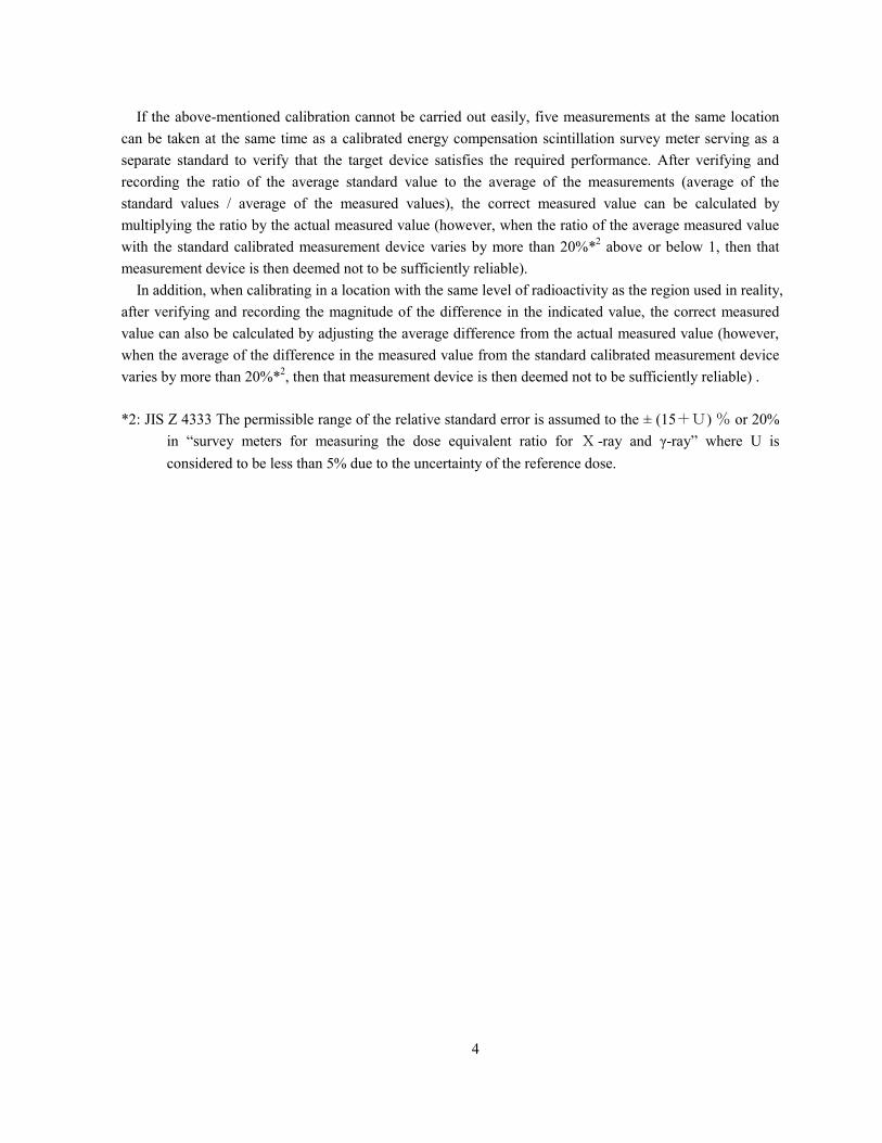
· Measuring points shall be four points in the facilities where waste is stored. An example of measuring
points is shown in Figure 2-1.
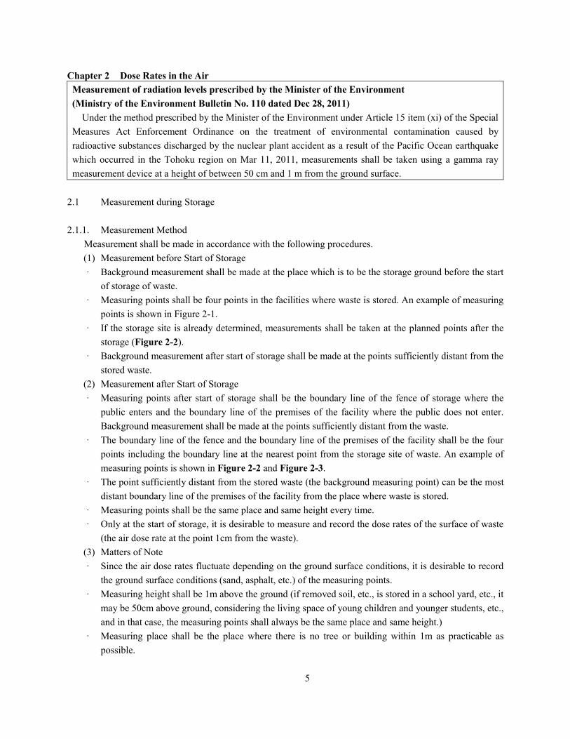
· If the storage site is already determined, measurements shall be taken at the planned points after the
storage (Figure 2-2).
· Background measurement after start of storage shall be made at the points sufficiently distant from the
stored waste.
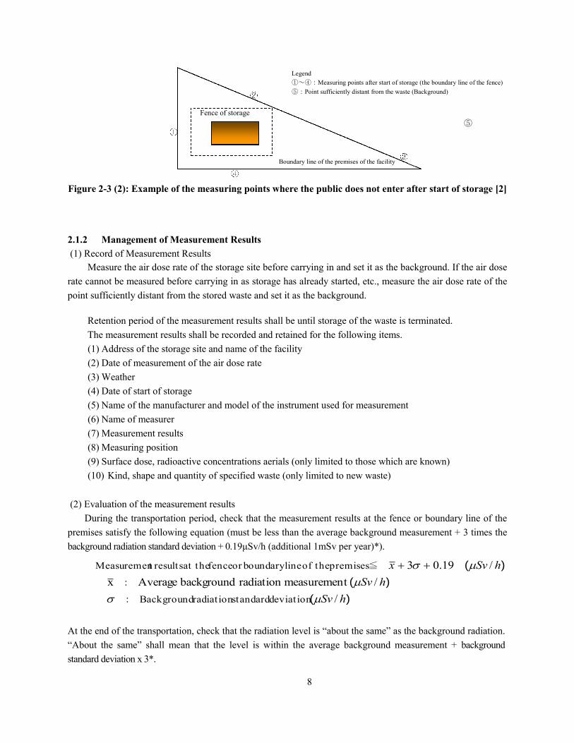
(2) Measurement after Start of Storage
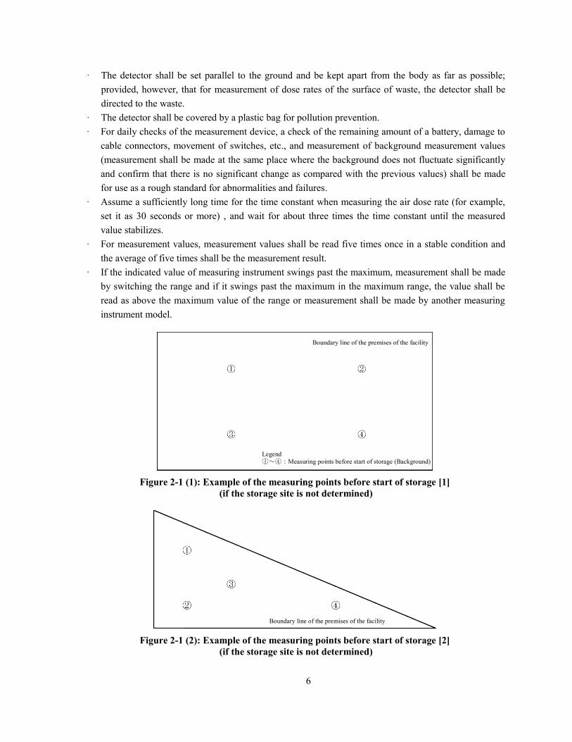
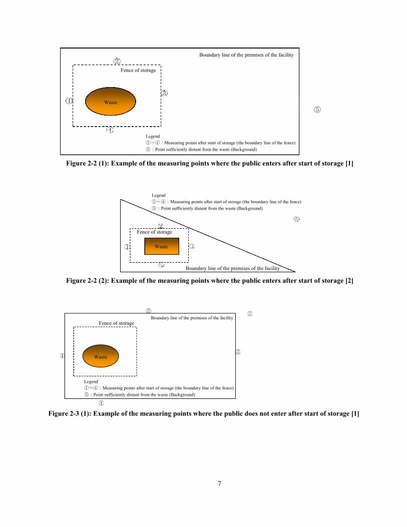
· Measuring points after start of storage shall be the boundary line of the fence of storage where the
public enters and the boundary line of the premises of the facility where the public does not enter.
Background measurement shall be made at the points sufficiently distant from the waste.
· The boundary line of the fence and the boundary line of the premises of the facility shall be the four
points including the boundary line at the nearest point from the storage site of waste. An example of
measuring points is shown in Figure 2-2 and Figure 2-3.
· The point sufficiently distant from the stored waste (the background measuring point) can be the most
distant boundary line of the premises of the facility from the place where waste is stored.
· Measuring points shall be the same place and same height every time.
· Only at the start of storage, it is desirable to measure and record the dose rates of the surface of waste
(the air dose rate at the point 1cm from the waste).
(3) Matters of Note
· Since the air dose rates fluctuate depending on the ground surface conditions, it is desirable to record
the ground surface conditions (sand, asphalt, etc.) of the measuring points.
· Measuring height shall be 1m above the ground (if removed soil, etc., is stored in a school yard, etc., it
may be 50cm above ground, considering the living space of young children and younger students, etc.,
and in that case, the measuring points shall always be the same place and same height.)
· Measuring place shall be the place where there is no tree or building within 1m as practicable as
possible.
6
· The detector shall be set parallel to the ground and be kept apart from the body as far as possible;
provided, however, that for measurement of dose rates of the surface of waste, the detector shall be
directed to the waste.
· The detector shall be covered by a plastic bag for pollution prevention.
· For daily checks of the measurement device, a check of the remaining amount of a battery, damage to
cable connectors, movement of switches, etc., and measurement of background measurement values
(measurement shall be made at the same place where the background does not fluctuate significantly
and confirm that there is no significant change as compared with the previous values) shall be made
for use as a rough standard for abnormalities and failures.
· Assume a sufficiently long time for the time constant when measuring the air dose rate (for example,
set it as 30 seconds or more) , and wait for about three times the time constant until the measured
value stabilizes.
· For measurement values, measurement values shall be read five times once in a stable condition and
the average of five times shall be the measurement result.
· If the indicated value of measuring instrument swings past the maximum, measurement shall be made
by switching the range and if it swings past the maximum in the maximum range, the value shall be
read as above the maximum value of the range or measurement shall be made by another measuring
instrument model.
Figure 2-1 (1): Example of the measuring points before start of storage [1]
(if the storage site is not determined)
Figure 2-1 (2): Example of the measuring points before start of storage [2]
(if the storage site is not determined)
Boundary line of the premises of the facility
Boundary line of the premises of the facility
Legend
①~④:Measuring points before start of storage (Background)
7
Figure 2-2 (1): Example of the measuring points where the public enters after start of storage [1]
Figure 2-2 (2): Example of the measuring points where the public enters after start of storage [2]
Figure 2-3 (1): Example of the measuring points where the public does not enter after start of storage [1]
Boundary line of the premises of the facility
Fence of storage
Waste
Boundary line of the premises of the facility
Fence of storage
Waste
Legend
①~④:Measuring points after start of storage (the boundary line of the fence)
⑤:Point sufficiently distant from the waste (Background)
Legend
①~④:Measuring points after start of storage (the boundary line of the fence)
⑤:Point sufficiently distant from the waste (Background)
Boundary line of the premises of the facility
Fence of storage
Waste
⑤
Legend
①~④:Measuring points after start of storage (the boundary line of the fence)
⑤:Point sufficiently distant from the waste (Background)
8
Figure 2-3 (2): Example of the measuring points where the public does not enter after start of storage [2]
2.1.2 Management of Measurement Results
(1) Record of Measurement Results
Measure the air dose rate of the storage site before carrying in and set it as the background. If the air dose
rate cannot be measured before carrying in as storage has already started, etc., measure the air dose rate of the
point sufficiently distant from the stored waste and set it as the background.
Retention period of the measurement results shall be until storage of the waste is terminated.
The measurement results shall be recorded and retained for the following items.
(1) Address of the storage site and name of the facility
(2) Date of measurement of the air dose rate
(3) Weather
(4) Date of start of storage
(5) Name of the manufacturer and model of the instrument used for measurement
(6) Name of measurer
(7) Measurement results
(8) Measuring position
(9) Surface dose, radioactive concentrations aerials (only limited to those which are known)
(10) Kind, shape and quantity of specified waste (only limited to new waste)
(2) Evaluation of the measurement results
During the transportation period, check that the measurement results at the fence or boundary line of the
premises satisfy the following equation (must be less than the average background measurement + 3 times the
background radiation standard deviation + 0.19μSv/h (additional 1mSv per year)*).
At the end of the transportation, check that the radiation level is “about the same” as the background radiation.
“About the same” shall mean that the level is within the average background measurement + background
standard deviation x 3*.
Fence of storage
Boundary line of the premises of the facility
)(
)(
)(
hSv
hSv
hSvx
/
/t measuremenradiation background Averagex
/19.03
deviat ion standardradiat ion Background:
:
≦premises theof lineboundary or fence at the resultst Measuremen
Legend
①~④:Measuring points after start of storage (the boundary line of the fence)
⑤:Point sufficiently distant from the waste (Background)
⑤
9
*According to the Nuclear Power Safety Committee’s “Environmental Radiation Monitoring Guidelines”
(partially revised in Apr. 2010), “when significant multiple measurements are obtained under well-controlled
conditions such as the measurements obtained chronologically from a single monitoring post, these
measurements shall be managed statistically and a normal fluctuation band of the previous average
measurement plus/minus three times the standard deviation shall be assumed.
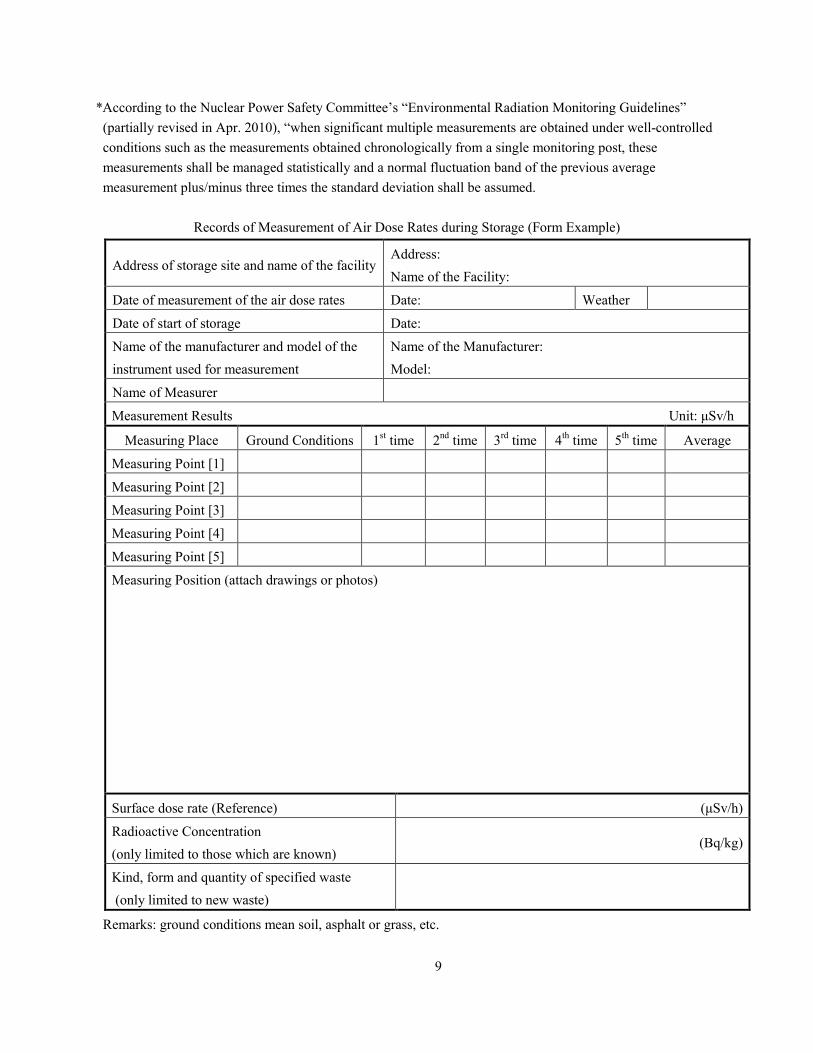
Records of Measurement of Air Dose Rates during Storage (Form Example)
Remarks: ground conditions mean soil, asphalt or grass, etc.
Address of storage site and name of the facility Address:
Name of the Facility:
Date of measurement of the air dose rates Date: Weather
Date of start of storage Date:
Name of the manufacturer and model of the
instrument used for measurement
Name of the Manufacturer:
Model:
Name of Measurer
Measurement Results Unit: μSv/h
Measuring Place Ground Conditions 1st time 2
nd time 3
rd time 4
th time 5
th time Average
Measuring Point [1]
Measuring Point [2]
Measuring Point [3]
Measuring Point [4]
Measuring Point [5]
Measuring Position (attach drawings or photos)
Surface dose rate (Reference) (μSv/h)
Radioactive Concentration
(only limited to those which are known) (Bq/kg)
Kind, form and quantity of specified waste
(only limited to new waste)
10
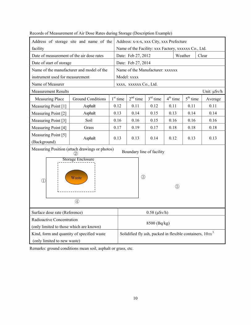
Records of Measurement of Air Dose Rates during Storage (Description Example)
Remarks: ground conditions mean soil, asphalt or grass, etc.
Address of storage site and name of the
facility
Address: x-x-x, xxx City, xxx Prefecture
Name of the Facility: xxx Factory, xxxxxx Co., Ltd.
Date of measurement of the air dose rates Date: Feb 27, 2012 Weather Clear
Date of start of storage Date: Feb 27, 2014
Name of the manufacturer and model of the
instrument used for measurement
Name of the Manufacturer: xxxxxx
Model: xxxx
Name of Measurer xxxx, xxxxxx Co., Ltd.
Measurement Results Unit: μSv/h
Measuring Place Ground Conditions 1st time 2
nd time 3
rd time 4
th time 5
th time Average
Measuring Point [1] Asphalt 0.12 0.11 0.12 0.11 0.11 0.11
Measuring Point [2] Asphalt 0.13 0.14 0.15 0.13 0.14 0.14
Measuring Point [3] Soil 0.16 0.16 0.15 0.16 0.16 0.16
Measuring Point [4] Grass 0.17 0.19 0.17 0.18 0.18 0.18
Measuring Point [5]
(Background) Asphalt 0.13 0.13 0.14 0.12 0.13 0.13
Measuring Position (attach drawings or photos)
Surface dose rate (Reference) 0.58 (μSv/h)
Radioactive Concentration
(only limited to those which are known) 8500 (Bq/kg)
Kind, form and quantity of specified waste
(only limited to new waste)
Solidified fly ash, packed in flexible containers, 10m3
Boundary line of facility ②
Storage Enclosure
① ③
⑤
④
Waste
11
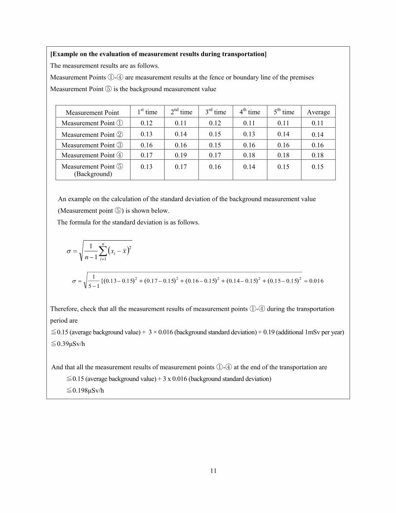
[Example on the evaluation of measurement results during transportation]
The measurement results are as follows.
Measurement Points ①-④ are measurement results at the fence or boundary line of the premises
Measurement Point ⑤ is the background measurement value
Measurement Point 1st time 2
nd time 3
rd time 4
th time 5
th time Average
Measurement Point ① 0.12 0.11 0.12 0.11 0.11 0.11
Measurement Point ② 0.13 0.14 0.15 0.13 0.14 0.14
Measurement Point ③ 0.16 0.16 0.15 0.16 0.16 0.16
Measurement Point ④ 0.17 0.19 0.17 0.18 0.18 0.18
Measurement Point ⑤ (Background)
0.13 0.17 0.16 0.14 0.15 0.15
An example on the calculation of the standard deviation of the background measurement value
(Measurement point ⑤) is shown below.
The formula for the standard deviation is as follows.
n
i
i xxn 1
2
1
1
016.015.015.015.014.015.016.015.017.015.013.015
1 22222 )()()()(){(
Therefore, check that all the measurement results of measurement points ①-④ during the transportation
period are
≦0.15 (average background value) + 3 × 0.016 (background standard deviation) + 0.19 (additional 1mSv per year)
≦0.39μSv/h
And that all the measurement results of measurement points ①-④ at the end of the transportation are
≦0.15 (average background value) + 3 x 0.016 (background standard deviation)
≦0.198μSv/h
12
2.2 Measurement during Transportation
2.2.1 Measurement Method
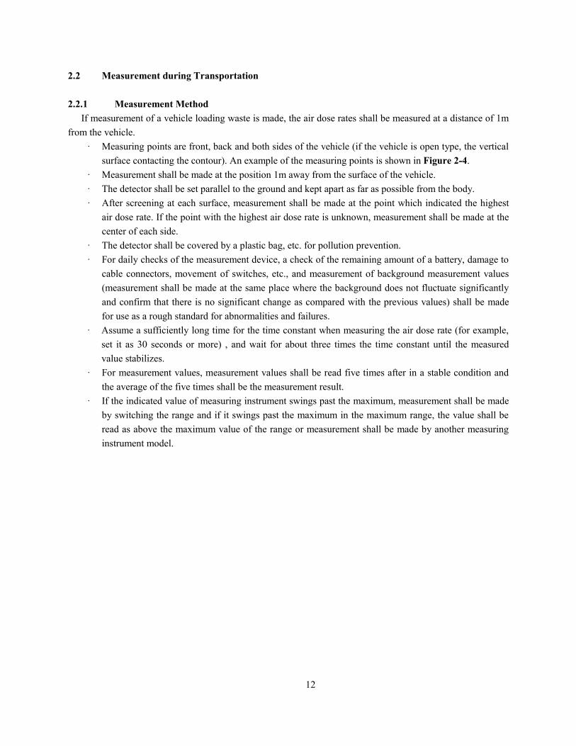
If measurement of a vehicle loading waste is made, the air dose rates shall be measured at a distance of 1m
from the vehicle.
· Measuring points are front, back and both sides of the vehicle (if the vehicle is open type, the vertical
surface contacting the contour). An example of the measuring points is shown in Figure 2-4.
· Measurement shall be made at the position 1m away from the surface of the vehicle.
· The detector shall be set parallel to the ground and kept apart as far as possible from the body.
· After screening at each surface, measurement shall be made at the point which indicated the highest
air dose rate. If the point with the highest air dose rate is unknown, measurement shall be made at the
center of each side.
· The detector shall be covered by a plastic bag, etc. for pollution prevention.
· For daily checks of the measurement device, a check of the remaining amount of a battery, damage to
cable connectors, movement of switches, etc., and measurement of background measurement values
(measurement shall be made at the same place where the background does not fluctuate significantly
and confirm that there is no significant change as compared with the previous values) shall be made
for use as a rough standard for abnormalities and failures.
· Assume a sufficiently long time for the time constant when measuring the air dose rate (for example,
set it as 30 seconds or more) , and wait for about three times the time constant until the measured
value stabilizes.
· For measurement values, measurement values shall be read five times after in a stable condition and
the average of the five times shall be the measurement result.
· If the indicated value of measuring instrument swings past the maximum, measurement shall be made
by switching the range and if it swings past the maximum in the maximum range, the value shall be
read as above the maximum value of the range or measurement shall be made by another measuring
instrument model.

13
Figure 2-4: Example of Measuring Points [1]
Side
Measuring position
Side
Measuring position
Front
Measuring position
* After screening at each surface, measurement shall be made at the point which
indicated the highest air dose rate. If the point with the highest air dose rate is
unknown, measurement shall be made at the center of each side.
Side
Measuring position
Back
Measuring position
Back
Measuring position Front
Measuring position
14
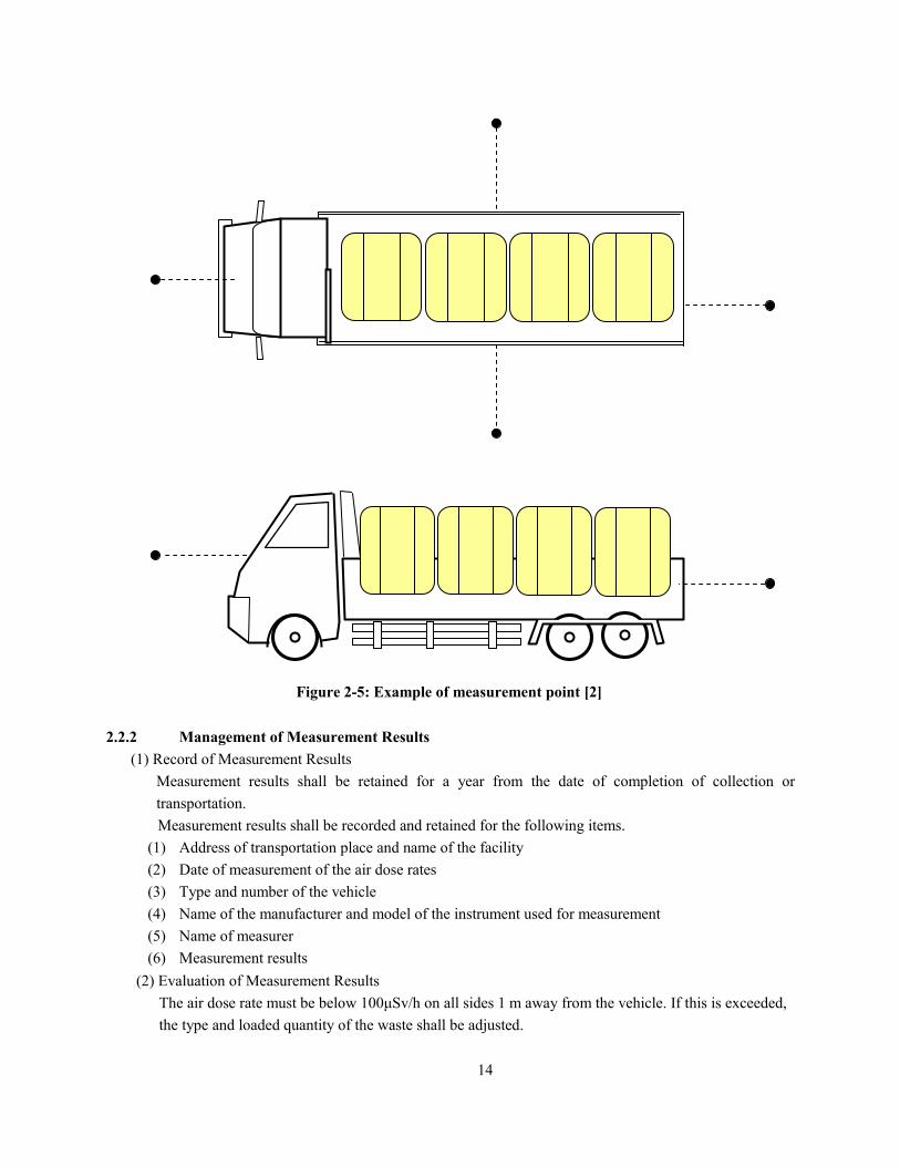
Figure 2-5: Example of measurement point [2]
2.2.2 Management of Measurement Results
(1) Record of Measurement Results
Measurement results shall be retained for a year from the date of completion of collection or
transportation.
Measurement results shall be recorded and retained for the following items.
(1) Address of transportation place and name of the facility
(2) Date of measurement of the air dose rates
(3) Type and number of the vehicle
(4) Name of the manufacturer and model of the instrument used for measurement
(5) Name of measurer
(6) Measurement results
(2) Evaluation of Measurement Results
The air dose rate must be below 100μSv/h on all sides 1 m away from the vehicle. If this is exceeded,
the type and loaded quantity of the waste shall be adjusted.

15
Records of Measurement of Air Dose Rates during Transportation (Form Example)
Address of transportation place,
name of the facility
Address:
Name of the Facility:
Date of measurement of air dose
rates Date:
Type of vehicle
Number of vehicle
Name of the manufacturer and
model of the instrument used for
measurement
Name of the Manufacturer:
Model:
Name of Measurer
Measurement Results Unit: μSv/h
Measuring Side 1st time 2
nd time 3
rd time 4
th time 5
th time Average
Front
Left side
Right side
Back

16
Records of Measurement of Air Dose Rates during Transportation (Description Example)
Address of transportation place,
name of the facility
Address: x-x-x, xxx City, xxx Prefecture
Name of the Facility: xxx Factory, xxx Co., Ltd.
Date of measurement of air dose
rates Date: Feb 27, 2012
Type of vehicle 10-t truck with canopy
Number of vehicle Chiba 100 A 12-34
Name of the manufacturer and
model of the instrument used for
measurement
Name of the Manufacturer: xxxxxx
Model: xxxx
Name of Measurer Company Name: xxx Co., Ltd. Name of Measurer: xxxxxx
Measurement Results Unit: μSv/h
Measuring Side 1st time 2
nd time 3
rd time 4
th time 5
th time Average
Front 0.25 0.23 0.26 0.22 0.25 0.24
Left side 1.56 1.62 1.58 1.55 1.64 1.59
Right side 1.85 1.76 1.80 1.77 1.82 1.80
Back 0.89 0.85 0.84 0.86 0.88 0.86

17
2.3 Measurement at Incineration Facilities, Sludge Dehydration Facilities, etc.
2.3.1 Measurement Method
Measurement shall be made in accordance with the following procedures.
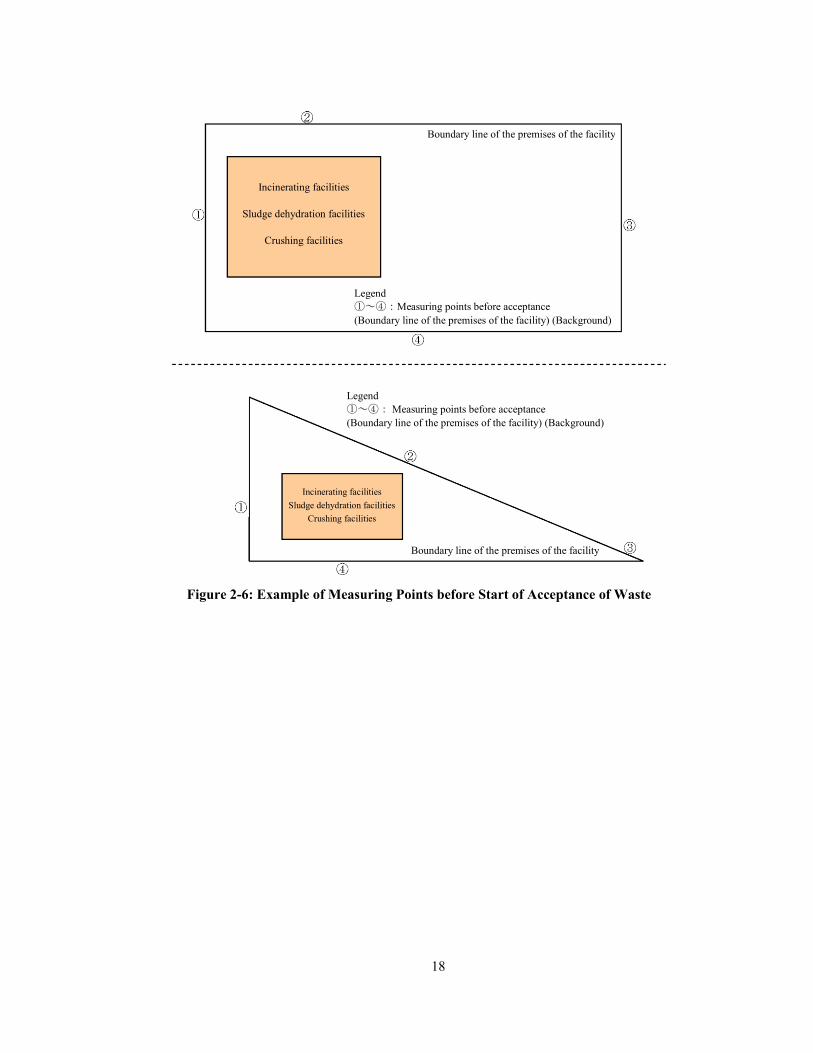
(1) Measurement before start of acceptance of waste
· Before start of acceptance of waste, at the boundary line of the premises, background measurement
shall be made. An example of measuring points is shown in Figure 2-6.
· Background measurement shall be made at the point sufficiently distant from the incineration facility
when waste has already been accepted and the incineration facility started operation.
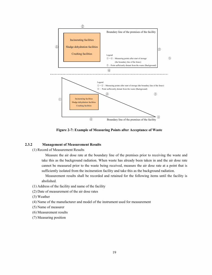
(2) Measurement after acceptance of waste
· Measuring points after acceptance of waste shall be four points including the boundary line of the
premises nearest to the facilities of incineration, etc. Background measurement shall be made at the
point sufficiently distant from the incineration facility. An example of measuring points is shown in
Figure 2-7.
· The point sufficiently distant from the facilities of incineration, etc. (background measuring points)
may be the boundary line of the premises farthest from the facilities of incineration, etc., of waste.
· Measuring points shall be the same every time.
(3) Matters of Note
· Since the air dose rates fluctuate depending on the ground surface conditions, it is desirable to record
the ground surface conditions (sand, asphalt, etc.) of the measuring points.
· Measuring height shall be 1m above the ground.
· Measuring place shall be the place where there is no tree or building within 1m as practicable as
possible.
· The detector shall be set parallel to the ground and be kept apart from the body as far as possible.
· The detector shall be covered by a plastic bag, etc. for pollution prevention.
· For daily checks of the measurement device, a check of the remaining amount of a battery, damage to
cable connectors, movement of switches, etc., and measurement of background measurement values
(measurement shall be made at the same place where the background does not fluctuate significantly
and confirm that there is no significant change as compared with the previous values) shall be made
for use as a rough standard for abnormalities and failures.
· Assume a sufficiently long time for the time constant when measuring the air dose rate (for example,
set it as 30 seconds or more) , and wait for about three times the time constant until the measured
value stabilizes.
· For measurement values, measurement values shall be read five times once in a stable condition and
the average of five times shall be the measurement result.
· If the indicated value of measuring instrument swings past the maximum, measurement shall be made
by switching the range and if it swings past the maximum in the maximum range, the value shall be
read as above the maximum value of the range or measurement shall be made by another measuring
instrument model.
18
Figure 2-6: Example of Measuring Points before Start of Acceptance of Waste
Incinerating facilities
Sludge dehydration facilities
Crushing facilities
Legend
①~④:Measuring points before acceptance
(Boundary line of the premises of the facility) (Background)
Legend
①~④: Measuring points before acceptance
(Boundary line of the premises of the facility) (Background)
Boundary line of the premises of the facility
Incinerating facilities
Sludge dehydration facilities
Crushing facilities
Boundary line of the premises of the facility
19
Figure 2-7: Example of Measuring Points after Acceptance of Waste
2.3.2 Management of Measurement Results
(1) Record of Measurement Results
Measure the air dose rate at the boundary line of the premises prior to receiving the waste and
take this as the background radiation. When waste has already been taken in and the air dose rate
cannot be measured prior to the waste being received, measure the air dose rate at a point that is
sufficiently isolated from the incineration facility and take this as the background radiation.
Measurement results shall be recorded and retained for the following items until the facility is
abolished.
(1) Address of the facility and name of the facility
(2) Date of measurement of the air dose rates
(3) Weather
(4) Name of the manufacturer and model of the instrument used for measurement
(5) Name of measurer
(6) Measurement results
(7) Measuring position
Boundary line of the premises of the facility
Boundary line of the premises of the facility
Legend
①~④:Measuring points after start of storage
(the boundary line of the fence)
⑤:Point sufficiently distant from the waste (Background)
Legend
①~④:Measuring points after start of storage (the boundary line of the fence)
⑤: Point sufficiently distant from the waste (Background)
Incinerating facilities
Sludge dehydration facilities
Crushing facilities
Incinerating facilities
Sludge dehydration facilities
Crushing facilities
⑤
20
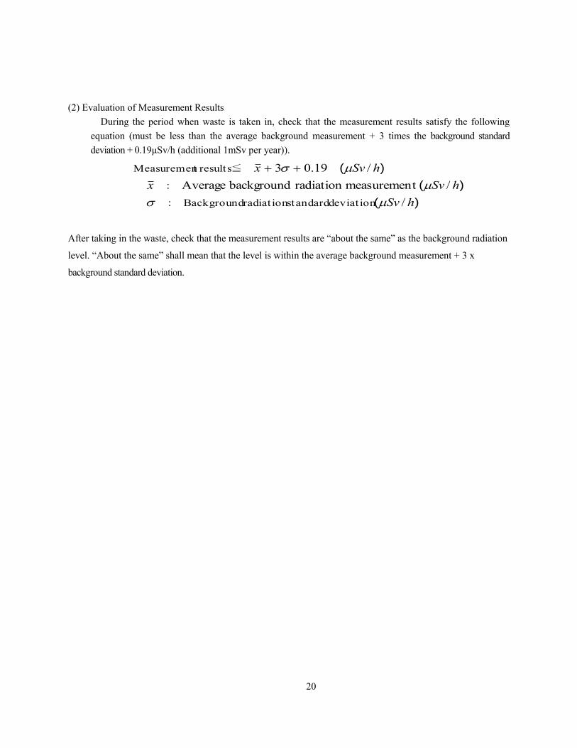
(2) Evaluation of Measurement Results
During the period when waste is taken in, check that the measurement results satisfy the following
equation (must be less than the average background measurement + 3 times the background standard
deviation + 0.19μSv/h (additional 1mSv per year)).
)(
)(
)(
hSv
hSvx
hSvx
/
/tmeasuremenradiation background Average
/19.03
deviat ion standardradiat ion Background:
:
≦ resultst Measuremen
After taking in the waste, check that the measurement results are “about the same” as the background radiation
level. “About the same” shall mean that the level is within the average background measurement + 3 x
background standard deviation.
21
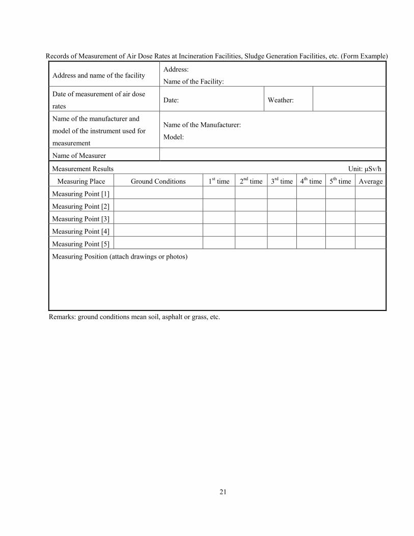
Records of Measurement of Air Dose Rates at Incineration Facilities, Sludge Generation Facilities, etc. (Form Example)
Address and name of the facility Address:
Name of the Facility:
Date of measurement of air dose
rates Date: Weather:
Name of the manufacturer and
model of the instrument used for
measurement
Name of the Manufacturer:
Model:
Name of Measurer
Measurement Results Unit: μSv/h
Measuring Place Ground Conditions 1st time 2
nd time 3
rd time 4
th time 5
th time Average
Measuring Point [1]
Measuring Point [2]
Measuring Point [3]
Measuring Point [4]
Measuring Point [5]
Measuring Position (attach drawings or photos)
Remarks: ground conditions mean soil, asphalt or grass, etc.
22
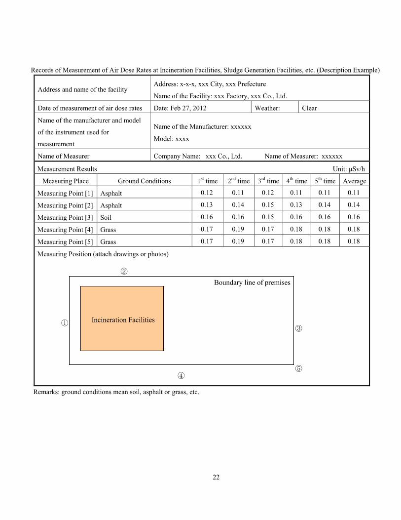
Records of Measurement of Air Dose Rates at Incineration Facilities, Sludge Generation Facilities, etc. (Description Example)
Address and name of the facility Address: x-x-x, xxx City, xxx Prefecture
Name of the Facility: xxx Factory, xxx Co., Ltd.
Date of measurement of air dose rates Date: Feb 27, 2012 Weather: Clear
Name of the manufacturer and model
of the instrument used for
measurement
Name of the Manufacturer: xxxxxx
Model: xxxx
Name of Measurer Company Name: xxx Co., Ltd. Name of Measurer: xxxxxx
Measurement Results Unit: μSv/h
Measuring Place Ground Conditions 1st time 2
nd time 3
rd time 4
th time 5
th time Average
Measuring Point [1] Asphalt 0.12 0.11 0.12 0.11 0.11 0.11
Measuring Point [2] Asphalt 0.13 0.14 0.15 0.13 0.14 0.14
Measuring Point [3] Soil 0.16 0.16 0.15 0.16 0.16 0.16
Measuring Point [4] Grass 0.17 0.19 0.17 0.18 0.18 0.18
Measuring Point [5] Grass 0.17 0.19 0.17 0.18 0.18 0.18
Measuring Position (attach drawings or photos)
Remarks: ground conditions mean soil, asphalt or grass, etc.
②
Incineration Facilities ① ③
Boundary line of premises
⑤ ④

23
2.4 Measurement at Landfill Site
2.4.1 Measurement Method
Measurement shall be made in accordance with the following procedures.
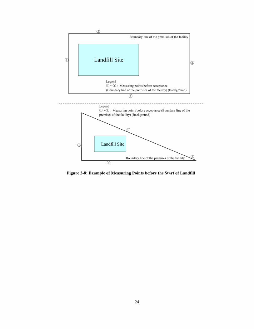
(1) Measurement before the start of landfill
· Before the start of landfill, at the boundary line of the premises, background measurement shall be
made. An example of measuring points is shown in Figure 2-8.
· Background measurement after the start of landfill shall be made at the point sufficiently distant from
the landfill site.
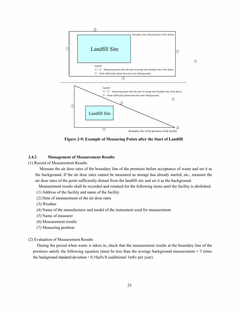
(2) Measurement after start of landfill
· Measuring points after the start of landfill shall be four points at the boundary line of the premises.
Background measurement shall be made at the point sufficiently distant from the landfill site.
An example of measuring points is shown in Figure 2-9.
· The point sufficiently distant from the landfill site (background measurement) may be the boundary
line of the premises with the longest distance from the landfill site to the premises.
· Measuring points at the boundary line of premises shall be the same every time.
(3) Matters of Note
· Since the air dose rate fluctuates according to the condition of the ground, it is desirable to record
down the condition of the ground (soil, asphalt, etc.) at the measurement point.
· Measuring height shall be 1m above the ground.
· Measuring place shall be the place where there is no tree or building within 1m as practicable as
possible.
· The detector shall be set parallel to the ground and be kept apart from the body as far as possible.
· The detector shall be covered by a plastic bag, etc. for pollution prevention.
· For daily checks of the measurement device, a check of the remaining amount of a battery, damage to
cable connectors, movement of switches, etc., and measurement of background measurement values
(measurement shall be made at the same place where the background does not fluctuate significantly
and confirm that there is no significant change as compared with the previous values) shall be made
for use as a rough standard for abnormalities and failures.
· Assume a sufficiently long time for the time constant when measuring the air dose rate (for example,
set it as 30 seconds or more) , and wait for about three times the time constant until the measured
value stabilizes.
· For measurement values, measurement values shall be read five times once in a stable condition and
the average of five times shall be the measurement result.
· If the indicated value of measuring instrument swings past the maximum, measurement shall be made
by switching the range and if it swings past the maximum in the maximum range, the value shall be
read as above the maximum value of the range or measurement shall be made by another measuring
instrument model.
24
Figure 2-8: Example of Measuring Points before the Start of Landfill
Boundary line of the premises of the facility
Boundary line of the premises of the facility
Landfill Site
Landfill Site
Legend
①~④:Measuring points before acceptance
(Boundary line of the premises of the facility) (Background)
Legend
①~④:Measuring points before acceptance (Boundary line of the
premises of the facility) (Background)
25
Figure 2-9: Example of Measuring Points after the Start of Landfill
2.4.2 Management of Measurement Results
(1) Record of Measurement Results
Measure the air dose rates of the boundary line of the premises before acceptance of waste and set it as
the background. If the air dose rates cannot be measured as storage has already started, etc., measure the
air dose rates of the point sufficiently distant from the landfill site and set it as the background.
Measurement results shall be recorded and retained for the following items until the facility is abolished.
(1) Address of the facility and name of the facility
(2) Date of measurement of the air dose rates
(3) Weather
(4) Name of the manufacturer and model of the instrument used for measurement
(5) Name of measurer
(6) Measurement results
(7) Measuring position
(2) Evaluation of Measurement Results
During the period when waste is taken in, check that the measurement results at the boundary line of the
premises satisfy the following equation (must be less than the average background measurement + 3 times
the background standard deviation + 0.19μSv/h (additional 1mSv per year).
Boundary line of the premises of the facility
Legend
①~④:Measuring points after the start of storage (the boundary line of the fence)
⑤:Point sufficiently distant from the waste (Background)
Boundary line of the premises of the facility
Landfill Site
Landfill Site
⑤
Legend
①~④:Measuring points after the start of storage (the boundary line of the fence)
⑤:Point sufficiently distant from the waste (Background)
26
)(
)(
)(
hSv
hSvx
hSvx
/
/tmeasuremenradiation background Average
/19.03
deviat ion standardradiat ion Background:
:
≦ resultst Measuremen
After taking in the waste, check that the measurement results are “about the same” as the background radiation
level. “About the same” shall mean that the level is within the average background measurement + 3 x
background standard deviation.

27
Records of Measurement of Air Dose Rates at Landfill Site, etc. (Form Example)
Address and name of the facility Address:
Name of the Facility:
Date of measurement of air dose rates Date: Weather:
Name of the manufacturer and model
of the instrument used for
measurement
Name of the Manufacturer:
Model:
Name of Measurer
Measurement Results Unit: μSv/h
Measuring Place Ground Conditions 1st time 2
nd time 3
rd time 4
th time 5
th time Average
Measuring Point [1]
Measuring Point [2]
Measuring Point [3]
Measuring Point [4]
Measuring Point [5]
Measuring Position (attach drawings or photos)
Remarks: ground conditions mean soil, asphalt or grass, etc.
28
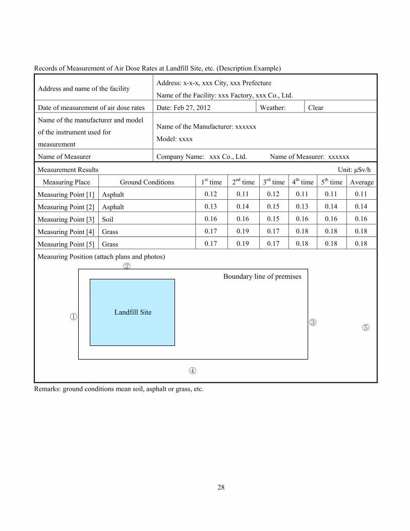
Records of Measurement of Air Dose Rates at Landfill Site, etc. (Description Example)
Address and name of the facility Address: x-x-x, xxx City, xxx Prefecture
Name of the Facility: xxx Factory, xxx Co., Ltd.
Date of measurement of air dose rates Date: Feb 27, 2012 Weather: Clear
Name of the manufacturer and model
of the instrument used for
measurement
Name of the Manufacturer: xxxxxx
Model: xxxx
Name of Measurer Company Name: xxx Co., Ltd. Name of Measurer: xxxxxx
Measurement Results Unit: μSv/h
Measuring Place Ground Conditions 1st time 2
nd time 3
rd time 4
th time 5
th time Average
Measuring Point [1] Asphalt 0.12 0.11 0.12 0.11 0.11 0.11
Measuring Point [2] Asphalt 0.13 0.14 0.15 0.13 0.14 0.14
Measuring Point [3] Soil 0.16 0.16 0.15 0.16 0.16 0.16
Measuring Point [4] Grass 0.17 0.19 0.17 0.18 0.18 0.18
Measuring Point [5] Grass 0.17 0.19 0.17 0.18 0.18 0.18
Measuring Position (attach plans and photos)
Remarks: ground conditions mean soil, asphalt or grass, etc.
Landfill Site ①
③
Boundary line of premises
⑤
④
②
29
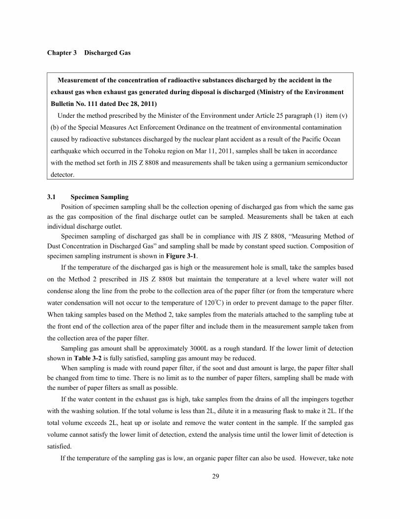
Chapter 3 Discharged Gas
Measurement of the concentration of radioactive substances discharged by the accident in the
exhaust gas when exhaust gas generated during disposal is discharged (Ministry of the Environment
Bulletin No. 111 dated Dec 28, 2011)
Under the method prescribed by the Minister of the Environment under Article 25 paragraph (1) item (v)
(b) of the Special Measures Act Enforcement Ordinance on the treatment of environmental contamination
caused by radioactive substances discharged by the nuclear plant accident as a result of the Pacific Ocean
earthquake which occurred in the Tohoku region on Mar 11, 2011, samples shall be taken in accordance
with the method set forth in JIS Z 8808 and measurements shall be taken using a germanium semiconductor
detector.
3.1 Specimen Sampling
Position of specimen sampling shall be the collection opening of discharged gas from which the same gas
as the gas composition of the final discharge outlet can be sampled. Measurements shall be taken at each
individual discharge outlet.
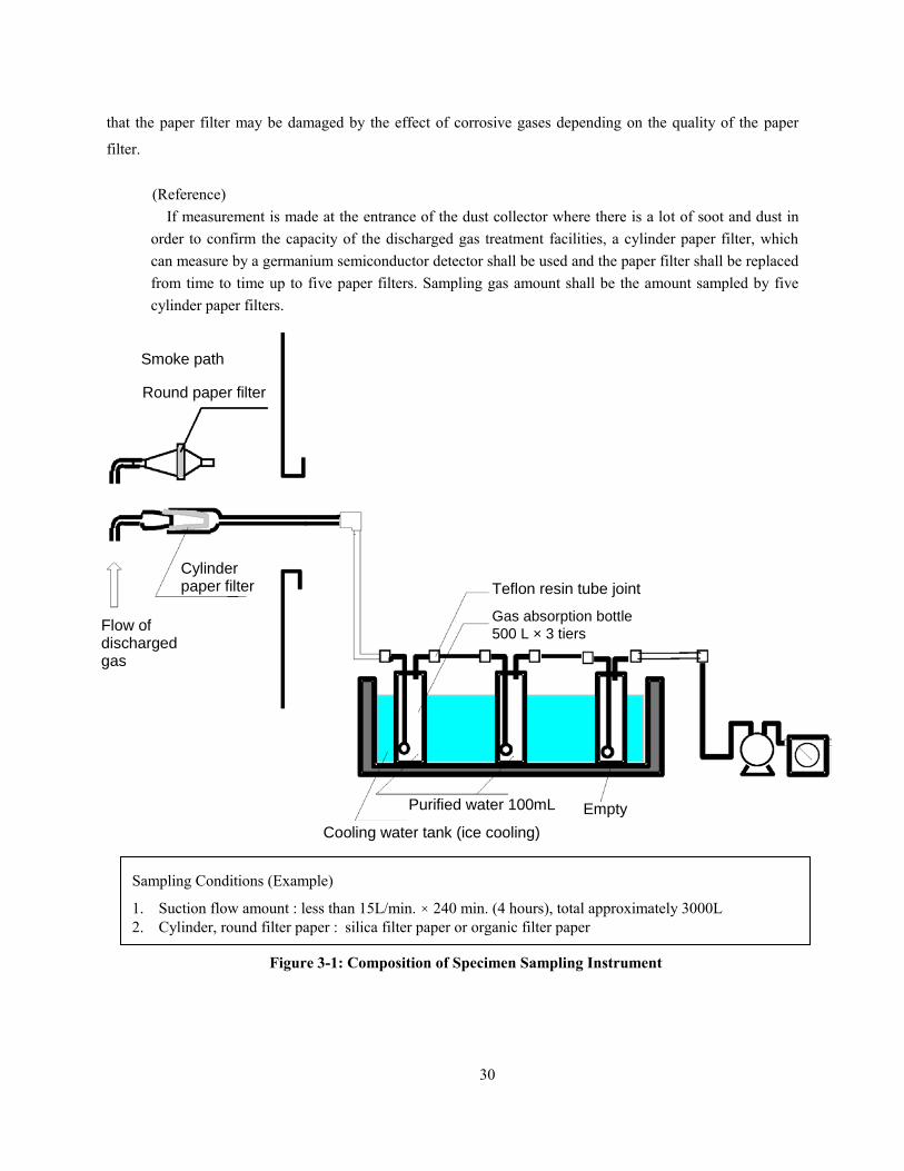
Specimen sampling of discharged gas shall be in compliance with JIS Z 8808, “Measuring Method of
Dust Concentration in Discharged Gas” and sampling shall be made by constant speed suction. Composition of
specimen sampling instrument is shown in Figure 3-1.
If the temperature of the discharged gas is high or the measurement hole is small, take the samples based
on the Method 2 prescribed in JIS Z 8808 but maintain the temperature at a level where water will not
condense along the line from the probe to the collection area of the paper filter (or from the temperature where
water condensation will not occur to the temperature of 120℃) in order to prevent damage to the paper filter.
When taking samples based on the Method 2, take samples from the materials attached to the sampling tube at
the front end of the collection area of the paper filter and include them in the measurement sample taken from
the collection area of the paper filter.
Sampling gas amount shall be approximately 3000L as a rough standard. If the lower limit of detection
shown in Table 3-2 is fully satisfied, sampling gas amount may be reduced.
When sampling is made with round paper filter, if the soot and dust amount is large, the paper filter shall
be changed from time to time. There is no limit as to the number of paper filters, sampling shall be made with
the number of paper filters as small as possible.
If the water content in the exhaust gas is high, take samples from the drains of all the impingers together
with the washing solution. If the total volume is less than 2L, dilute it in a measuring flask to make it 2L. If the
total volume exceeds 2L, heat up or isolate and remove the water content in the sample. If the sampled gas
volume cannot satisfy the lower limit of detection, extend the analysis time until the lower limit of detection is
satisfied.
If the temperature of the sampling gas is low, an organic paper filter can also be used. However, take note
30
that the paper filter may be damaged by the effect of corrosive gases depending on the quality of the paper
filter.
(Reference)
If measurement is made at the entrance of the dust collector where there is a lot of soot and dust in
order to confirm the capacity of the discharged gas treatment facilities, a cylinder paper filter, which
can measure by a germanium semiconductor detector shall be used and the paper filter shall be replaced
from time to time up to five paper filters. Sampling gas amount shall be the amount sampled by five
cylinder paper filters.
Figure 3-1: Composition of Specimen Sampling Instrument
Flow of discharged gas
Cylinder paper filter
Cooling water tank (ice cooling)
Empty
Smoke path
Round paper filter
Teflon resin tube joint
Gas absorption bottle
500 L × 3 tiers
Purified water 100mL
Sampling Conditions (Example)
1. Suction flow amount : less than 15L/min. × 240 min. (4 hours), total approximately 3000L
2. Cylinder, round filter paper : silica filter paper or organic filter paper

31
3.2 Management of Measurement Results
For the radioactive concentration in the discharged gas, measurement is generally made only at the
discharge outlet. If the measurement value exceeded the limit of concentration in the air around (Table 3-1,
the value provided for in the “Ordinance for Enforcement of the Act on Special Measures concerning the
Handling of Environment Pollution by Radioactive Materials Discharged by the Nuclear Power Station
Accident Associated with the Tohoku District - Off the Pacific Ocean Earthquake that Occurred on March
11, 2011”), the impact on the surrounding environment shall be determined by comparing the assumed
value and measurement value of concentrations in [1] -[3] below with the concentration limit.
[1] Concentrations at the maximum ground level concentration point presumed by the analysis of
movement of discharged gas.
[2] Concentrations of radioactive materials in the air measured at the maximum ground level
concentration point presumed in [1]
[3] Concentrations of radioactive materials in the air measured in four directions of the boundary of
premises around the facility
Measurement results shall be recorded and retained for the following items until the facility is abolished.
(1) Address of measuring place and name of the facility
(2) Date of specimen sampling
(3) Name of person sampling specimen
(4) Specimen sampling position
(5) Method of analysis of radioactive concentration
(6) Analysis Results
(7) Name of Analyzer
Table 3-1: Concentration Limit in the Air
Kind of radioactive materials Concentration limit in the air (Bq/m3)
Cesium-134 20
Cesium-137 30
Remarks 1: Concentration limit means that for the average concentration for three months, the value
calculated in accordance with the following formula (in case of cesium-134 and cesium-
137, the total of ratio to each concentration limit) shall not exceed 1.
Remarks 2: The idea of the average concentration for three months shall be as follows.
(1) Measurement shall be made at least once a month. The measurement values of cesium-
134 and cesium-137 shall be divided by 20 and 30 respectively and by totaling them,
the ratio of 1 shall be sought (effective to 2 significant digits).
(2) If measurement is made more than once a month, the average of the ratio sought in (1)
above (effective to 2 significant digits) shall be adopted and it shall be the
measurement value of the month.
(3) The average value for consecutive three months as to the calculation result in (2)
above shall be adopted and it shall be the “average concentration for three months,”
32
the concentration limit (effective to 2 significant digits).
(4) For example, if measurement is made from January through April, the average of
January, February and March and the average of February, March and April shall
respectively be the average value for three (3) consecutive months.
Concentration of cesium-134 (Bq/m3) /20 (Bq/m
3) + concentration of cesium-137 (Bq/m
3) /30 (Bq/m
3) ≤1
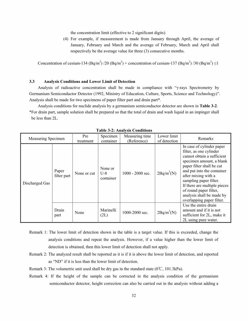
3.3 Analysis Conditions and Lower Limit of Detection
Analysis of radioactive concentration shall be made in compliance with “γ-rays Spectrometry by
Germanium Semiconductor Detector (1992, Ministry of Education, Culture, Sports, Science and Technology)”.
Analysis shall be made for two specimens of paper filter part and drain part*.
Analysis conditions for nuclide analysis by a germanium semiconductor detector are shown in Table 3-2.
*For drain part, sample solution shall be prepared so that the total of drain and wash liquid in an impinger shall
be less than 2L.
Table 3-2: Analysis Conditions
Measuring Specimen Pre
treatment
Specimen
container
Measuring time
(Reference)
Lower limit
of detection Remarks
Discharged Gas
Paper
filter part None or cut
None or
U-8
container
1000 - 2000 sec. 2Bq/m3(N)
In case of cylinder paper
filter, as one cylinder
cannot obtain a sufficient
specimen amount, a blank
paper filter shall be cut
and put into the container
after mixing with a
sampling paper filter.
If there are multiple pieces
of round paper filter,
analysis shall be made by
overlapping paper filter.
Drain
part None
Marinelli
(2L) 1000-2000 sec. 2Bq/m
3(N)
Use the entire drain
amount and if it is not
sufficient for 2L, make it
2L using pure water.
Remark 1: The lower limit of detection shown in the table is a target value. If this is exceeded, change the
analysis conditions and repeat the analysis. However, if a value higher than the lower limit of
detection is obtained, then this lower limit of detection shall not apply.
Remark 2: The analyzed result shall be reported as it is if it is above the lower limit of detection, and reported
as “ND” if it is less than the lower limit of detection.
Remark 3: The volumetric unit used shall be dry gas in the standard state (0℃, 101.3kPa).
Remark 4: If the height of the sample can be corrected in the analysis condition of the germanium
semiconductor detector, height correction can also be carried out in the analysis without adding a
33
blank paper filter.
Remark 5: The analyzed result shall be rounded to 2 significant figures in accordance with Rule B under JIS Z
8401 “Rounding of Figures”. In addition, the minimum number of digits displayed shall be up to
the number of digits of the lower limit of detection.
Remark 6: The lower limit of detection shall be shown for cesium-134 and cesium-137 respectively.
34
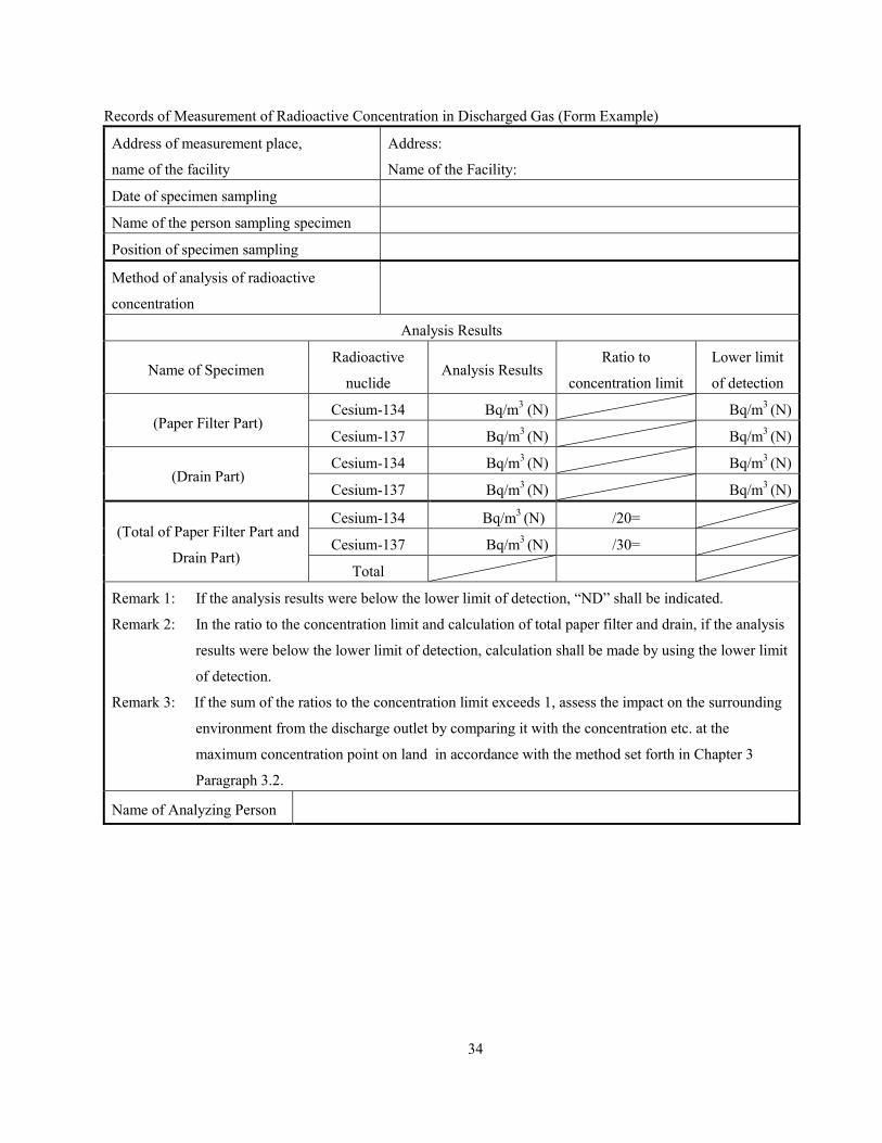
Records of Measurement of Radioactive Concentration in Discharged Gas (Form Example)
Address of measurement place,
name of the facility
Address:
Name of the Facility:
Date of specimen sampling
Name of the person sampling specimen
Position of specimen sampling
Method of analysis of radioactive
concentration
Analysis Results
Name of Specimen Radioactive
nuclide Analysis Results
Ratio to
concentration limit
Lower limit
of detection
(Paper Filter Part) Cesium-134 Bq/m
3 (N) Bq/m
3 (N)
Cesium-137 Bq/m3 (N) Bq/m
3 (N)
(Drain Part) Cesium-134 Bq/m
3 (N) Bq/m
3 (N)
Cesium-137 Bq/m3 (N) Bq/m
3 (N)
(Total of Paper Filter Part and
Drain Part)
Cesium-134 Bq/m3 (N) /20=
Cesium-137 Bq/m3 (N) /30=
Total
Remark 1: If the analysis results were below the lower limit of detection, “ND” shall be indicated.
Remark 2: In the ratio to the concentration limit and calculation of total paper filter and drain, if the analysis
results were below the lower limit of detection, calculation shall be made by using the lower limit
of detection.
Remark 3: If the sum of the ratios to the concentration limit exceeds 1, assess the impact on the surrounding
environment from the discharge outlet by comparing it with the concentration etc. at the
maximum concentration point on land in accordance with the method set forth in Chapter 3
Paragraph 3.2.
Name of Analyzing Person
35
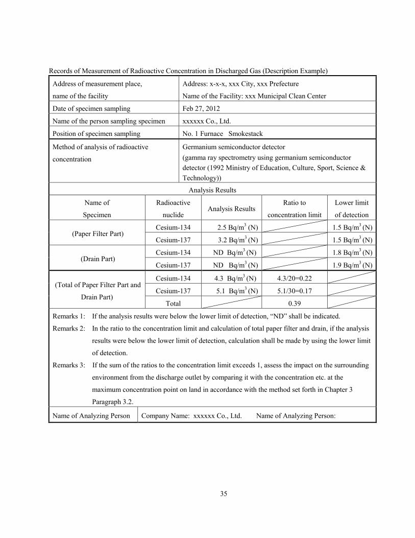
Records of Measurement of Radioactive Concentration in Discharged Gas (Description Example)
Address of measurement place,
name of the facility
Address: x-x-x, xxx City, xxx Prefecture
Name of the Facility: xxx Municipal Clean Center
Date of specimen sampling Feb 27, 2012
Name of the person sampling specimen xxxxxx Co., Ltd.
Position of specimen sampling No. 1 Furnace Smokestack
Method of analysis of radioactive
concentration
Germanium semiconductor detector
(gamma ray spectrometry using germanium semiconductor
detector (1992 Ministry of Education, Culture, Sport, Science &
Technology))
Analysis Results
Name of
Specimen
Radioactive
nuclide Analysis Results
Ratio to
concentration limit
Lower limit
of detection
(Paper Filter Part) Cesium-134 2.5 Bq/m
3 (N) 1.5 Bq/m
3 (N)
Cesium-137 3.2 Bq/m3 (N) 1.5 Bq/m
3 (N)
(Drain Part) Cesium-134 ND Bq/m
3 (N) 1.8 Bq/m
3 (N)
Cesium-137 ND Bq/m3 (N) 1.9 Bq/m
3 (N)
(Total of Paper Filter Part and
Drain Part)
Cesium-134 4.3 Bq/m3 (N) 4.3/20=0.22
Cesium-137 5.1 Bq/m3 (N) 5.1/30=0.17
Total 0.39
Remarks 1: If the analysis results were below the lower limit of detection, “ND” shall be indicated.
Remarks 2: In the ratio to the concentration limit and calculation of total paper filter and drain, if the analysis
results were below the lower limit of detection, calculation shall be made by using the lower limit
of detection.
Remarks 3: If the sum of the ratios to the concentration limit exceeds 1, assess the impact on the surrounding
environment from the discharge outlet by comparing it with the concentration etc. at the
maximum concentration point on land in accordance with the method set forth in Chapter 3
Paragraph 3.2.
Name of Analyzing Person Company Name: xxxxxx Co., Ltd. Name of Analyzing Person:

36
Chapter 4 Particulates
4.1 Specimen Sampling
(1) Open-type Crushing Facilities
Points of specimen sampling shall be the two points of the boundary of the premises on the
windward side and the boundary of the premises on the leeward side of the crushing facilities.
Wind direction shall be measured by a simple wind direction and wind speed meter (Reference
Photo 4-1) before sampling particulates.
A high-volume air sampler (Reference Photo 4-2) shall be used for specimen sampling and
suctioning shall be made for 30 minutes at 500L/min. If particulate amount is large, the paper filter shall
be replaced in the process of sampling.
Reference Photo 4-1:
Wind direction and wind speed meter
Reference Photo 4-2: High-volume air sampler
(2) Closed-type Crushing Facilities
Specimen sampling shall comply with JIS Z 8808, “Measurement Method of Dust Concentration in
Discharged Gas” and sampling shall be made by constant speed suction. In Figure 4-1, composition of
specimen sampling instrument is shown.
Sampling gas amount shall be approximately 3000L at the outlet. If there is a large amount of
particulates, the cylinder paper filter, which can measure by a germanium semiconductor detector, shall
be used and the paper filter shall be replaced from time to time up to five paper filters. Sampling gas
amount shall be the amount to be sampled by five cylinder paper filters.
When sampling is made with a round paper filter, if the particulates amount is large, the paper filter
shall be changed from time to time. There is no limit as to the number of paper filters, but sampling
shall be made with the number of paper filters as small as possible.
When the temperature of the collected gas is low, organic filter paper can also be used. However,
take note that the filter paper may be damaged due to the influence of corrosive gases etc. depending on
the quality of the filter.

37
Figure 4-1: Composition of Specimen Sampling Instrument
4.2 Management of Measurement Results
The measurement results shall be compared with the concentration limit in the air applied to facilities
discharging gas (Table 4-1).
Measurement results shall be recorded and retained for the following items.
(1) Address of measuring place and name of the facility
(2) Date of specimen sampling
(3) Name of person sampling specimen
(4) Wind direction and wind speed of open-type facilities
(5) Position of specimen sampling
(6) Method of analysis of radioactive concentration
(7) Analysis results
(8) Name of analyzing person
Exhaust Outlet
Round paper filter
Cylinder paper filter Teflon resin tube joint
Gas absorption bottle
500 L × 3 tiers
Purified water 100mL
Cooling water tank (ice cooling)
Empty
Flow of particulates
Sampling Conditions (Example)
1. Suction flow amount : Approximately 15L/min. × 240 minutes (4 hours), total approximately 3000L
2. Cylinder/Round Paper Filter : silica paper filter or organic paper filter
38
Table 4-1: Concentration Limit in the Air
Kind of radioactive materials Concentration limit in the air (Bq/m3)
Cesium-134 20
Cesium-137 30
Remark: The concentration limit applied to facilities discharging gas means that for the average
concentration for three months, the value calculated in accordance with the following formula (in
case of cesium-134 and cesium-137, the total of the ratio to each concentration limit) shall not
exceed 1.
Concentration of cesium-134 (Bq/m3) /20 (Bq/m
3) + concentration of cesium-137 (Bq/m
3) /30 (Bq/m
3) ≤1
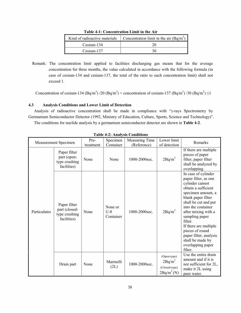
4.3 Analysis Conditions and Lower Limit of Detection
Analysis of radioactive concentration shall be made in compliance with “γ-rays Spectrometry by
Germanium Semiconductor Detector (1992, Ministry of Education, Culture, Sports, Science and Technology)”.
The conditions for nuclide analysis by a germanium semiconductor detector are shown in Table 4-2.
Table 4-2: Analysis Conditions
Measurement Specimen Pre-
treatment
Specimen
Container
Measuring Time
(Reference)
Lower limit
of detection Remarks
Particulates
Paper filter
part (open-
type crushing
facilities)
None None 1000-2000sec. 2Bq/m3
If there are multiple
pieces of paper
filter, paper filter
shall be analyzed by
overlapping.
Paper filter
part (closed-
type crushing
facilities)
None
None or
U-8
Container
1000-2000sec. 2Bq/m3
In case of cylinder
paper filter, as one
cylinder cannot
obtain a sufficient
specimen amount, a
blank paper filter
shall be cut and put
into the container
after mixing with a
sampling paper
filter.
If there are multiple
pieces of round
paper filter, analysis
shall be made by
overlapping paper
filter.
Drain part None Marinelli
(2L) 1000-2000sec.
(Open-type)
2Bq/m3
(Closed-type)
2Bq/m3
(N)
Use the entire drain
amount and if it is
not sufficient for 2L,
make it 2L using pure water.
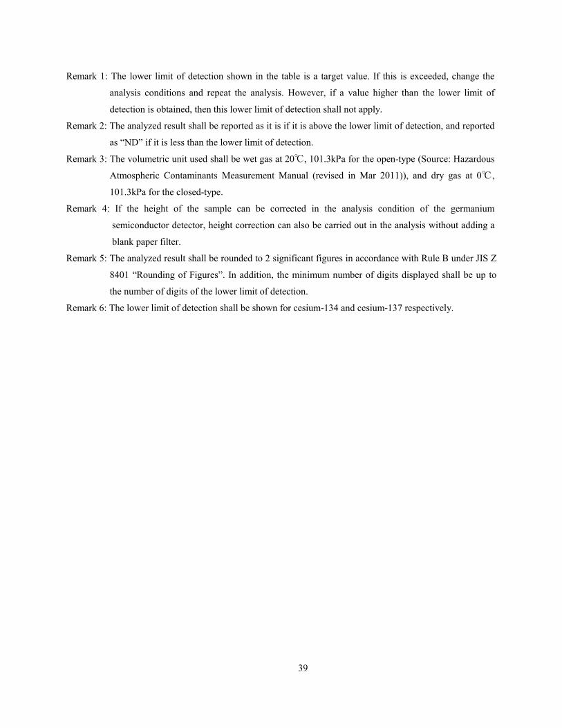
39
Remark 1: The lower limit of detection shown in the table is a target value. If this is exceeded, change the
analysis conditions and repeat the analysis. However, if a value higher than the lower limit of
detection is obtained, then this lower limit of detection shall not apply.
Remark 2: The analyzed result shall be reported as it is if it is above the lower limit of detection, and reported
as “ND” if it is less than the lower limit of detection.
Remark 3: The volumetric unit used shall be wet gas at 20℃, 101.3kPa for the open-type (Source: Hazardous
Atmospheric Contaminants Measurement Manual (revised in Mar 2011)), and dry gas at 0℃,
101.3kPa for the closed-type.
Remark 4: If the height of the sample can be corrected in the analysis condition of the germanium
semiconductor detector, height correction can also be carried out in the analysis without adding a
blank paper filter.
Remark 5: The analyzed result shall be rounded to 2 significant figures in accordance with Rule B under JIS Z
8401 “Rounding of Figures”. In addition, the minimum number of digits displayed shall be up to
the number of digits of the lower limit of detection.
Remark 6: The lower limit of detection shall be shown for cesium-134 and cesium-137 respectively.

40
Records of Measurement of Radioactive Concentration in Particulates (Open-type) (Form Example)
Address of measurement place,
name of the facility
Address:
Name of the Facility:
Date of specimen sampling Date: Weather
Name of the person sampling
specimen
Wind direction and wind speed
Position of sampling specimen (attach drawings or photos)
Method of analysis of radioactive
concentration
Analysis Results
Name of Specimen Radioactive
nuclide
Analysis Results Ratio to
concentration limit
Lower limit of
detection
(Windward)
Cesium-134 Bq/m3 /20 = Bq/m
3
Cesium-137 Bq/m3 /30 = Bq/m
3
Total
(Leeward)
Cesium-134 Bq/m3 /20= Bq/m
3
Cesium-137 Bq/m3 /30= Bq/m
3
Total
Remarks 1: If the analysis results were below the lower limit of detection, “ND” shall be indicated.
Remarks 2: In the ratio to the concentration limit, if the analysis results were below the lower limit of detection,
calculation shall be made by using the lower limit of detection.
Name of Analyzing Person

41
Records of Measurement of Radioactive Concentration in Particulates (Open-type) (Description Example)
Address of measurement place,
name of the facility
Address: x-x-x, xxx City, xxx Prefecture
Name of the Facility: xxx Municipal Clean Center
Date of specimen sampling Date: Feb 27, 2012 Weather Clear
Name of the person sampling
specimen
xxxxxx Co., Ltd.
Wind direction and wind speed Northwest 2.5 m/s
Position of sampling specimen (attach drawings or photos)
Method of analysis of radioactive
concentration
Germanium semiconductor detector
(gamma ray spectrometry using germanium semiconductor detector (1992
Ministry of Education, Culture, Sport, Science & Technology))
Analysis Results
Name of
Specimen
Radioactive
nuclide
Analysis Results Ratio to
concentration limit
Lower limit of
detection
Crushing Facility (Windward)
Cesium-134 ND Bq/m3 1.4/20 =0.07 1.4 Bq/m
3
Cesium-137 ND Bq/m3 1.5/30 =0.05 1.5 Bq/m
3
Total 0.12
Crushing Facility (Leeward)
Cesium-134 2.4 Bq/m3 2.4/20= 0.12 1.4 Bq/m
3
Cesium-137 2.8 Bq/m3 2.8/30=0.09 1.5 Bq/m
3
Total 0.21
Remarks 1: If the analysis results were below the lower limit of detection, “ND” shall be indicated.
Remarks 2: In the ratio to the concentration limit, if the analysis results were below the lower limit of detection,
calculation shall be made by using the lower limit of detection.
Name of Analyzing Person Company Name: xxxxxx Co., Ltd. Name of Analyzing Person:
Crushing Facility
●Windward
●Leeward
N
42
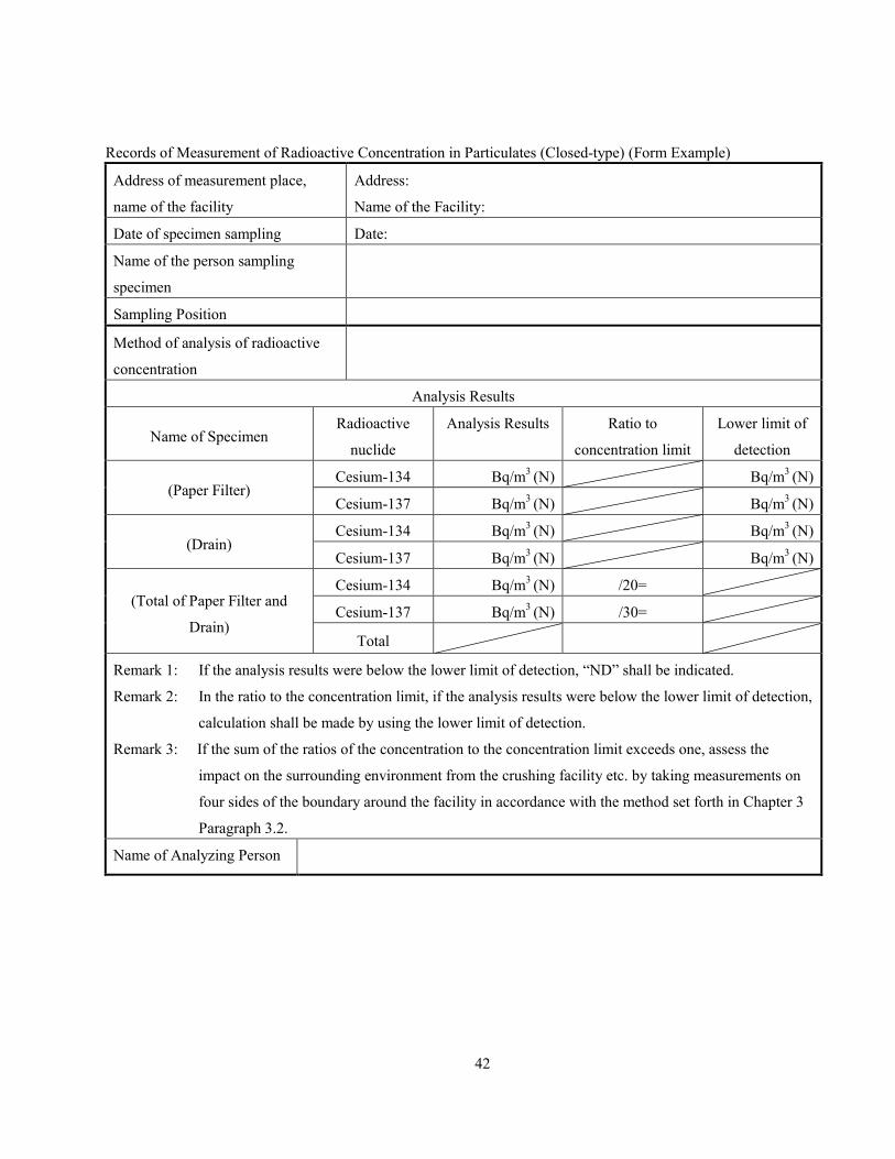
Records of Measurement of Radioactive Concentration in Particulates (Closed-type) (Form Example)
Address of measurement place,
name of the facility
Address:
Name of the Facility:
Date of specimen sampling Date:
Name of the person sampling
specimen
Sampling Position
Method of analysis of radioactive
concentration
Analysis Results
Name of Specimen Radioactive
nuclide
Analysis Results Ratio to
concentration limit
Lower limit of
detection
(Paper Filter) Cesium-134 Bq/m
3 (N) Bq/m
3 (N)
Cesium-137 Bq/m3 (N) Bq/m
3 (N)
(Drain) Cesium-134 Bq/m
3 (N) Bq/m
3 (N)
Cesium-137 Bq/m3 (N) Bq/m
3 (N)
(Total of Paper Filter and
Drain)
Cesium-134 Bq/m3 (N) /20=
Cesium-137 Bq/m3 (N) /30=
Total
Remark 1: If the analysis results were below the lower limit of detection, “ND” shall be indicated.
Remark 2: In the ratio to the concentration limit, if the analysis results were below the lower limit of detection,
calculation shall be made by using the lower limit of detection.
Remark 3: If the sum of the ratios of the concentration to the concentration limit exceeds one, assess the
impact on the surrounding environment from the crushing facility etc. by taking measurements on
four sides of the boundary around the facility in accordance with the method set forth in Chapter 3
Paragraph 3.2.
Name of Analyzing Person
43
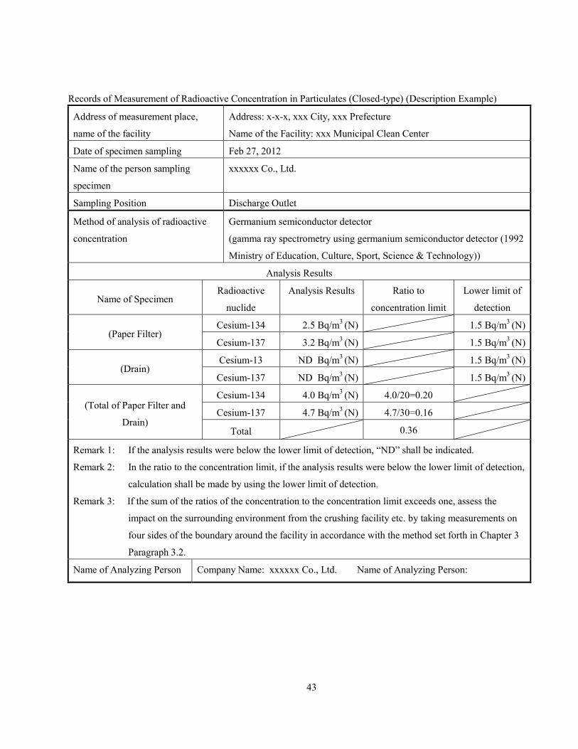
Records of Measurement of Radioactive Concentration in Particulates (Closed-type) (Description Example)
Address of measurement place,
name of the facility
Address: x-x-x, xxx City, xxx Prefecture
Name of the Facility: xxx Municipal Clean Center
Date of specimen sampling Feb 27, 2012
Name of the person sampling
specimen
xxxxxx Co., Ltd.
Sampling Position Discharge Outlet
Method of analysis of radioactive
concentration
Germanium semiconductor detector
(gamma ray spectrometry using germanium semiconductor detector (1992
Ministry of Education, Culture, Sport, Science & Technology))
Analysis Results
Name of Specimen Radioactive
nuclide
Analysis Results Ratio to
concentration limit
Lower limit of
detection
(Paper Filter) Cesium-134 2.5 Bq/m
3 (N) 1.5 Bq/m
3 (N)
Cesium-137 3.2 Bq/m3 (N) 1.5 Bq/m
3 (N)
(Drain) Cesium-13 ND Bq/m
3 (N) 1.5 Bq/m
3 (N)
Cesium-137 ND Bq/m3 (N) 1.5 Bq/m
3 (N)
(Total of Paper Filter and
Drain)
Cesium-134 4.0 Bq/m3 (N) 4.0/20=0.20
Cesium-137 4.7 Bq/m3 (N) 4.7/30=0.16
Total 0.36
Remark 1: If the analysis results were below the lower limit of detection, “ND” shall be indicated.
Remark 2: In the ratio to the concentration limit, if the analysis results were below the lower limit of detection,
calculation shall be made by using the lower limit of detection.
Remark 3: If the sum of the ratios of the concentration to the concentration limit exceeds one, assess the
impact on the surrounding environment from the crushing facility etc. by taking measurements on
four sides of the boundary around the facility in accordance with the method set forth in Chapter 3
Paragraph 3.2.
Name of Analyzing Person Company Name: xxxxxx Co., Ltd. Name of Analyzing Person:
44
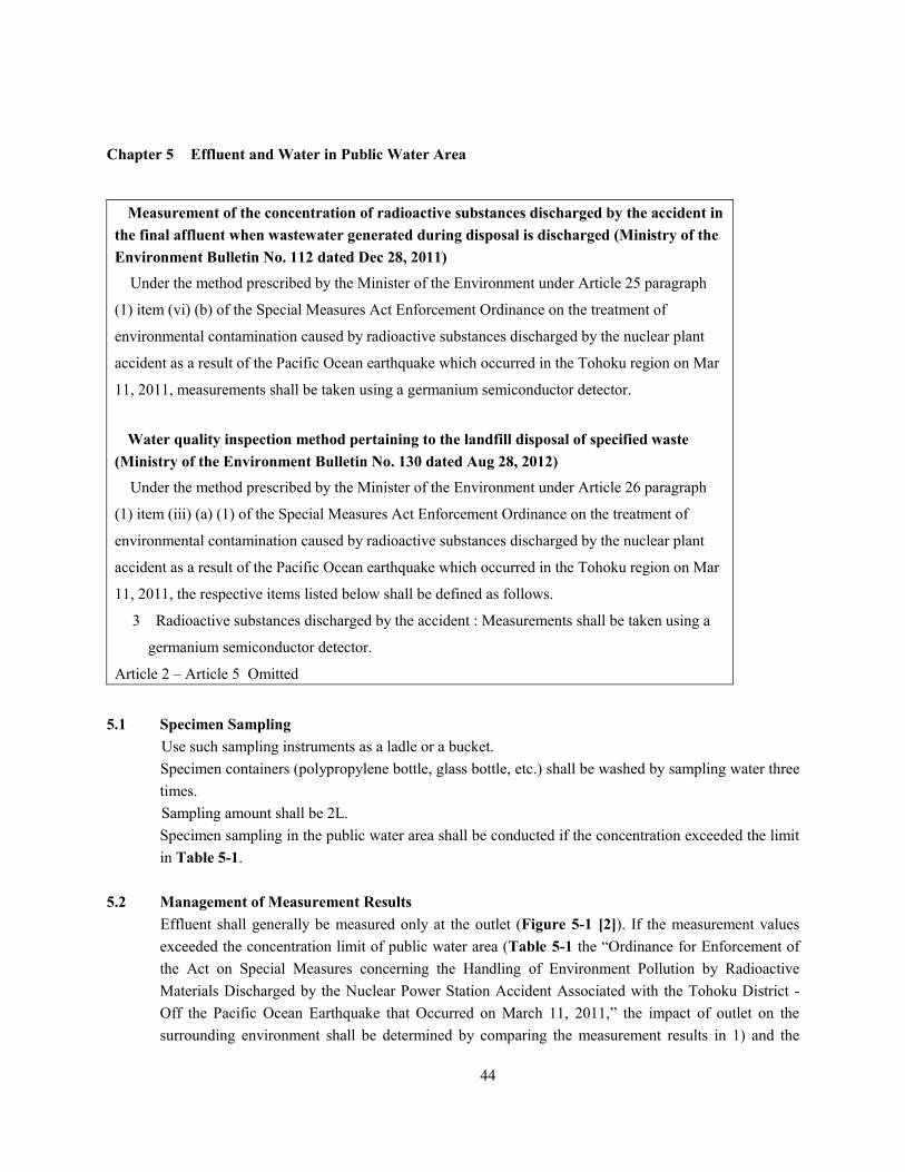
Chapter 5 Effluent and Water in Public Water Area
Measurement of the concentration of radioactive substances discharged by the accident in
the final affluent when wastewater generated during disposal is discharged (Ministry of the
Environment Bulletin No. 112 dated Dec 28, 2011)
Under the method prescribed by the Minister of the Environment under Article 25 paragraph
(1) item (vi) (b) of the Special Measures Act Enforcement Ordinance on the treatment of
environmental contamination caused by radioactive substances discharged by the nuclear plant
accident as a result of the Pacific Ocean earthquake which occurred in the Tohoku region on Mar
11, 2011, measurements shall be taken using a germanium semiconductor detector.
Water quality inspection method pertaining to the landfill disposal of specified waste
(Ministry of the Environment Bulletin No. 130 dated Aug 28, 2012)
Under the method prescribed by the Minister of the Environment under Article 26 paragraph
(1) item (iii) (a) (1) of the Special Measures Act Enforcement Ordinance on the treatment of
environmental contamination caused by radioactive substances discharged by the nuclear plant
accident as a result of the Pacific Ocean earthquake which occurred in the Tohoku region on Mar
11, 2011, the respective items listed below shall be defined as follows.
3 Radioactive substances discharged by the accident : Measurements shall be taken using a
germanium semiconductor detector.
Article 2 – Article 5 Omitted
5.1 Specimen Sampling
Use such sampling instruments as a ladle or a bucket.
Specimen containers (polypropylene bottle, glass bottle, etc.) shall be washed by sampling water three
times.
Sampling amount shall be 2L.
Specimen sampling in the public water area shall be conducted if the concentration exceeded the limit
in Table 5-1.
5.2 Management of Measurement Results
Effluent shall generally be measured only at the outlet (Figure 5-1 [2]). If the measurement values
exceeded the concentration limit of public water area (Table 5-1 the “Ordinance for Enforcement of
the Act on Special Measures concerning the Handling of Environment Pollution by Radioactive
Materials Discharged by the Nuclear Power Station Accident Associated with the Tohoku District -
Off the Pacific Ocean Earthquake that Occurred on March 11, 2011,” the impact of outlet on the
surrounding environment shall be determined by comparing the measurement results in 1) and the

45
concentration limit.
1) The point nearest to the outlet, where the concentrations of radioactive materials in the effluent, which
is located upstream of the water intake gate or interflowing side streams or the outlet of other facilities
(Figure 5-1 [1]) and interflowing with public water basin, can be stably measured.
· Sampling point where water can stably be measured means the point where there is no variation in
values after measurements two to three times almost simultaneously.
· Where stocking is made to the closed conduit in a public water area, if sampling is impossible around
the effluent outlet, measurement shall be made at the point nearest to the effluent outlet, where the
concentrations of radioactive materials in the effluent can be stably measured (point of interflowing
with rivers and open conduits). If there is a manhole, from which sampling of a specimen is possible,
at the nearer point to the effluent outlet than the interflowing point, however, the specimen shall be
sampled at that point.
Measurement results shall be recorded and retained for the following items until the facility is abolished.
(1) Address of the facility, name of the facility
(2) Date of specimen sampling
(3) Weather
(4) Name of the person sampling specimen
(5) Position of specimen sampling
(6) Method of specimen sampling (sampling instrument)
(7) Amount of specimen sampling
(8) Specimen container
(9) Method of analysis of radioactive concentration
(10) Analysis Results
(11) Name of the analyzing person

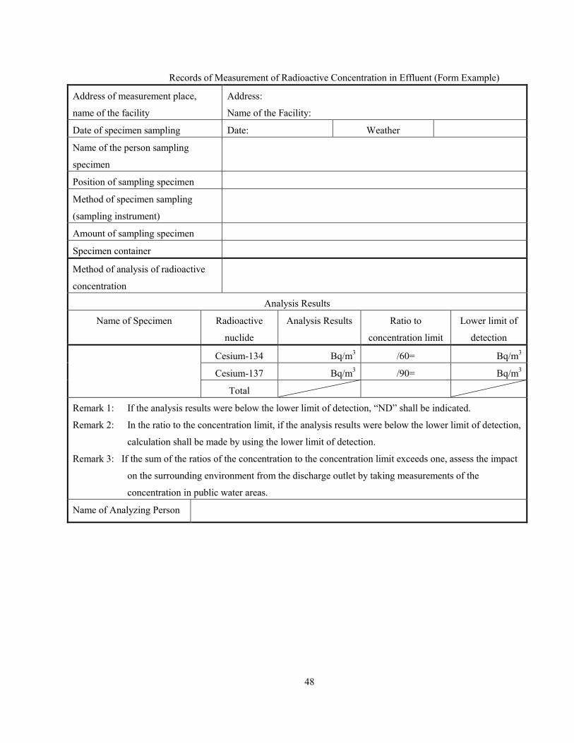
46
Figure 5-1: Example of Sampling Points
Table 5-1: Concentration limit in the public water area
Kind of radioactive materials Concentration limit in the public water area (Bq/L)
Cesium-134 60
Cesium-137 90
Remark 1: Concentration limit means that for the average concentration for three months, the value
calculated in accordance with the following formula (in case of cesium-134 and cesium-
137, the total of ratio to each concentration limit) shall not exceed 1.
Remark 2: The idea of the average concentration for three months shall be as follows.
(1) Measurement shall be made at least once a month. The measurement values of cesium-
134 and cesium-137 shall be divided by 60 and 90 respectively and by totaling them,
the ratio to 1 shall be sought (rounded to 2 significant digits).
(2) If measurement is made more than once a month, the average of the ratios sought in
(1) above (rounded to 2 significant digits) shall be adopted and it shall be the
measurement value of the month.
(3) The average value for consecutive three months as to the calculation result in (2)
above shall be adopted and it shall be the “average concentration for three months,” or
the concentration limit (rounded to 2 significant digits).
(4) For example, if measurement is made from January through April, the average of
January, February and March and the average of February, March and April shall
respectively be the average value for three (3) consecutive months.
Concentration of cesium-134 (Bq/L) /60 (Bq/L) + concentration of cesium-137 (Bq/L) /90 (Bq/L) ≤ 1
5.3 Analysis Conditions and Lower Limit of Detection
Analysis of radioactive concentration shall be made in compliance with “γ-rays Spectrometry by
Germanium Semiconductor Detector (1992, Ministry of Education, Culture, Sports, Science and Technology).
Interim treatment
facilities, etc.
(1) Downstream
(2) Discharge outlet
Water intake gate
Discharge outlet of other facility,
side stream

47
Conditions for nuclide analysis by a germanium semiconductor detector are shown in Table 5-2.
Table 5-2: Analysis Conditions
Measurement specimen Pre-treatment Specimen container Measuring time
(Reference)
Lower limit
of detection
Effluent None U-8 Container 1000~2000sec. 10~20 Bq/L
Public water area None Marinelli (2L) 1000~2000sec. 1~2 Bq/L
Remark 1: The lower limit of detection shown in the table is a target value. If this is exceeded, change
the analysis conditions and repeat the analysis. However, if a value higher than the lower
limit of detection is obtained, then this lower limit of detection shall not apply.
Remark 2: The analyzed result is reported as it is if it is above the lower limit of detection, and
reported as “ND” if it is less than the lower limit of detection.
Remark 3: When checking for minute radiation concentration in water effluent in a specimen
container, the analysis can also be done using a Marinelli (2L) container.
Remark 4: The analyzed result shall be rounded to 2 significant figures in accordance with Rule B
under JIS Z 8401 “Rounding of Figures”. In addition, the minimum number of digits
displayed shall be up to the number of digits of the lower limit of detection.
Remark 5: The lower limit of detection shall be shown for cesium-134 and cesium-137 respectively.
48
Records of Measurement of Radioactive Concentration in Effluent (Form Example)
Address of measurement place,
name of the facility
Address:
Name of the Facility:
Date of specimen sampling Date: Weather
Name of the person sampling
specimen
Position of sampling specimen
Method of specimen sampling
(sampling instrument)
Amount of sampling specimen
Specimen container
Method of analysis of radioactive
concentration
Analysis Results
Name of Specimen Radioactive
nuclide
Analysis Results Ratio to
concentration limit
Lower limit of
detection
Cesium-134 Bq/m3 /60= Bq/m
3
Cesium-137 Bq/m3 /90= Bq/m
3
Total
Remark 1: If the analysis results were below the lower limit of detection, “ND” shall be indicated.
Remark 2: In the ratio to the concentration limit, if the analysis results were below the lower limit of detection,
calculation shall be made by using the lower limit of detection.
Remark 3: If the sum of the ratios of the concentration to the concentration limit exceeds one, assess the impact
on the surrounding environment from the discharge outlet by taking measurements of the
concentration in public water areas.
Name of Analyzing Person
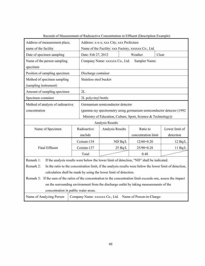
49
Records of Measurement of Radioactive Concentration in Effluent (Description Example)
Address of measurement place,
name of the facility
Address: x-x-x, xxx City, xxx Prefecture
Name of the Facility: xxx Factory, xxxxxx Co., Ltd.
Date of specimen sampling Date: Feb 27, 2012 Weather Clear
Name of the person sampling
specimen
Company Name: xxxxxx Co., Ltd. Sampler Name:
Position of sampling specimen Discharge container
Method of specimen sampling
(sampling instrument)
Stainless steel bucket
Amount of sampling specimen 2L
Specimen container 2L polyvinyl bottle
Method of analysis of radioactive
concentration
Germanium semiconductor detector
(gamma ray spectrometry using germanium semiconductor detector (1992
Ministry of Education, Culture, Sport, Science & Technology))
Analysis Results
Name of Specimen Radioactive
nuclide
Analysis Results Ratio to
concentration limit
Lower limit of
detection
Final Effluent
Cesium-134 ND Bq/L 12/60=0.20 12 Bq/L
Cesium-137 25 Bq/L 25/90=0.28 11 Bq/L
Total 0.48
Remark 1: If the analysis results were below the lower limit of detection, “ND” shall be indicated.
Remark 2: In the ratio to the concentration limit, if the analysis results were below the lower limit of detection,
calculation shall be made by using the lower limit of detection.
Remark 3: If the sum of the ratios of the concentration to the concentration limit exceeds one, assess the impact
on the surrounding environment from the discharge outlet by taking measurements of the
concentration in public water areas.
Name of Analyzing Person Company Name: xxxxxx Co., Ltd. Name of Person-in-Charge:

50
Records of Measurement of Radioactive Concentration in Public Water Area (Form Example)
Address of measurement place,
name of the facility
Address:
Name of the Facility:
Date of specimen sampling Date: Weather
Name of the person sampling
specimen
Method of specimen sampling
(sampling instrument)
Amount of sampling specimen
Specimen container
Position of sampling specimen (attach drawings or photos)
Method of analysis of radioactive
concentration
Analysis Results
Name of Specimen Radioactive
nuclide
Analysis Results Ratio to
concentration limit
Lower limit of
detection
Cesium-134 Bq/L /60= Bq/L
Cesium-137 Bq/L /90= Bq/L
Total
Remark 1: If the analysis results were below the lower limit of detection, “ND” shall be indicated.
Remark 2: In the ratio to the concentration limit, if the analysis results were below the lower limit of detection,
calculation shall be made by using the lower limit of detection.
Name of Analyzing Person
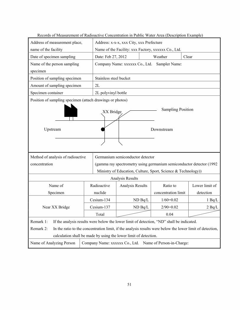
51
Records of Measurement of Radioactive Concentration in Public Water Area (Description Example)
Address of measurement place,
name of the facility
Address: x-x-x, xxx City, xxx Prefecture
Name of the Facility: xxx Factory, xxxxxx Co., Ltd.
Date of specimen sampling Date: Feb 27, 2012 Weather Clear
Name of the person sampling
specimen
Company Name: xxxxxx Co., Ltd. Sampler Name:
Position of sampling specimen Stainless steel bucket
Amount of sampling specimen 2L
Specimen container 2L polyvinyl bottle
Position of sampling specimen (attach drawings or photos)
Method of analysis of radioactive
concentration
Germanium semiconductor detector
(gamma ray spectrometry using germanium semiconductor detector (1992
Ministry of Education, Culture, Sport, Science & Technology))
Analysis Results
Name of
Specimen
Radioactive
nuclide
Analysis Results Ratio to
concentration limit
Lower limit of
detection
Near XX Bridge
Cesium-134 ND Bq/L 1/60=0.02 1 Bq/L
Cesium-137 ND Bq/L 2/90=0.02 2 Bq/L
Total 0.04
Remark 1: If the analysis results were below the lower limit of detection, “ND” shall be indicated.
Remark 2: In the ratio to the concentration limit, if the analysis results were below the lower limit of detection,
calculation shall be made by using the lower limit of detection.
Name of Analyzing Person Company Name: xxxxxx Co., Ltd. Name of Person-in-Charge:
Upstream Downstream
XX Bridge Sampling Position
52
Chapter 6 Surrounding Groundwater
Method to measure concentration of radioactive substances discharged by the
accident pertaining to water quality inspection of groundwater as prescribed
under Article 26 paragraph (1) item (iii) (a) of the Special Measures Act
Enforcement Ordinance on the treatment of environmental contamination caused
by radioactive substances discharged by the nuclear plant accident as a result of the
Pacific Ocean earthquake which occurred in the Tohoku region on Mar 11, 2011
(Ministry of the Environment Bulletin No. 113 dated Dec 28, 2011)
Among the methods prescribed by the Minister of the Environment under Article 26
paragraph (1) item (iii) (a) of the Special Measures Act Enforcement Ordinance on the
treatment of environmental contamination caused by radioactive substances discharged
by the nuclear plant accident as a result of the Pacific Ocean earthquake which occurred
in the Tohoku region on Mar 11, 2011, those pertaining to radioactive substances
discharged by the accident (as prescribed under Article 1 of the Special Measures Act
(2011 Act No. 110) on the treatment of environmental contamination caused by
radioactive substances discharged by the nuclear plant accident as a result of the Pacific
Ocean earthquake which occurred in the Tohoku region on Mar 11, 2011) shall be
measured using a germanium semiconductor detector.
Method to measure concentration of radioactive substances discharged by the
accident pertaining to water quality inspection of groundwater as prescribed
under Article 26 paragraph (4) item (ii) (a) of the Special Measures Act
Enforcement Ordinance on the treatment of environmental contamination caused
by radioactive substances discharged by the nuclear plant accident as a result of the
Pacific Ocean earthquake which occurred in the Tohoku region on Mar 11, 2011
(Ministry of the Environment Bulletin No. 115 dated Dec 28, 2011) Among the methods prescribed by the Minister of the Environment under Article 26
paragraph (4) item (ii) (a) (1) of the Special Measures Act Enforcement Ordinance on the
treatment of environmental contamination caused by radioactive substances discharged
by the nuclear plant accident as a result of the Pacific Ocean earthquake which occurred
in the Tohoku region on Mar 11, 2011, those pertaining to radioactive substances
discharged by the accident (as prescribed under Article 1 of the Special Measures Act
(2011 Act No. 110) on the treatment of environmental contamination caused by
radioactive substances discharged by the nuclear plant accident as a result of the Pacific
Ocean earthquake which occurred in the Tohoku region on Mar 11, 2011) shall be
measured using a germanium semiconductor detector.
6.1 Specimen Sampling
Sampling of specimen shall be made at the observation well or well at the storage site, etc., if the flowing
direction of groundwater is known and the flowing direction can be assumed. If the flowing direction is
unknown, sampling shall be made at the observation well or well nearest to the storage site, etc. The flowing
direction of groundwater may be assumed by land shape (slope of ground surface and related position with
nearby rivers, etc.) If assumption is difficult, it is desirable to sample at more than two wells located at the
position surrounding the site. Even if the observation well or well is near, it is necessary to avoid measurement
of the upstream groundwater.
Measurements for final disposal sites are taken at the upstream and downstream observation wells.

53
Sampling instrument shall be bailer (Reference Photo 6-1) and water pump, etc.
Specimen containers (polyethylene bottle, glass bottle) shall be washed by sampling water three times.
Sampling amount shall be 2L.
Reference Photo 6-1: Groundwater sampling instrument (Bailer)
6.2 Management of Measurement Results
It shall be confirmed by measurement of the surrounding groundwater that the value of radioactive
cesium is not abnormal (must be lower than the lower limit of detection etc. (refer to 6.3)).
Measurement results shall be recorded and retained for the following items. Retention period of
measurement results shall be by the end of storage of the waste.
(1) Address of the storage site, name of the facility
(2) Date of start of storage
(3) Date of sampling specimen
(4) Weather
(5) Name of the person sampling specimen
(6) Method of specimen sampling (sampling instrument)
(7) Amount of specimen sampling
(8) Specimen container
(9) Position of specimen sampling
(10) Method of analysis of radioactive concentration
(11) Analysis results
(12) Name of the analyzing person
(13) Surface dose, radioactive concentration (only limited to those which are known)
(14) Kind and form of specified waste (only limited to new (changed) waste)
6.3 Analysis Conditions and Lower Limit of Detection
Analysis of radioactive concentration shall be made in compliance with “γ-rays Spectrometry by
Germanium Semiconductor Detector (1992, Ministry of Education, Culture, Sports, Science and Technology).
Analysis conditions for nuclide analysis by a germanium semiconductor detector are shown in Table 6-1.
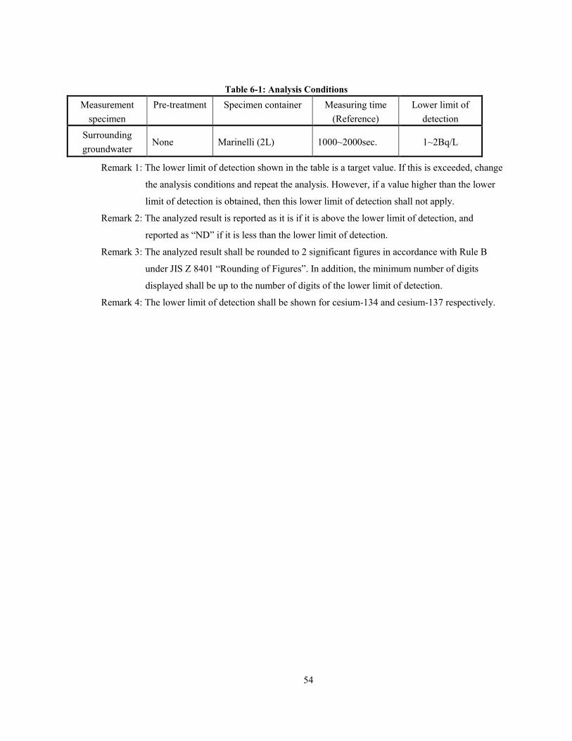
54
Table 6-1: Analysis Conditions
Measurement
specimen
Pre-treatment Specimen container Measuring time
(Reference)
Lower limit of
detection
Surrounding
groundwater None Marinelli (2L) 1000~2000sec. 1~2Bq/L
Remark 1: The lower limit of detection shown in the table is a target value. If this is exceeded, change
the analysis conditions and repeat the analysis. However, if a value higher than the lower
limit of detection is obtained, then this lower limit of detection shall not apply.
Remark 2: The analyzed result is reported as it is if it is above the lower limit of detection, and
reported as “ND” if it is less than the lower limit of detection.
Remark 3: The analyzed result shall be rounded to 2 significant figures in accordance with Rule B
under JIS Z 8401 “Rounding of Figures”. In addition, the minimum number of digits
displayed shall be up to the number of digits of the lower limit of detection.
Remark 4: The lower limit of detection shall be shown for cesium-134 and cesium-137 respectively.
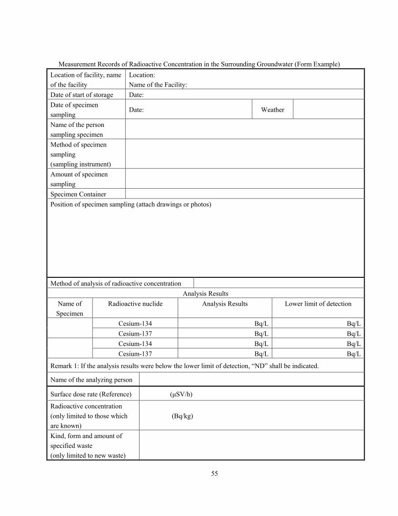
55
Measurement Records of Radioactive Concentration in the Surrounding Groundwater (Form Example)
Location of facility, name
of the facility
Location:
Name of the Facility:
Date of start of storage Date:
Date of specimen
sampling Date: Weather
Name of the person
sampling specimen
Method of specimen
sampling
(sampling instrument)
Amount of specimen
sampling
Specimen Container
Position of specimen sampling (attach drawings or photos)
Method of analysis of radioactive concentration
Analysis Results
Name of
Specimen
Radioactive nuclide Analysis Results Lower limit of detection
Cesium-134 Bq/L Bq/L
Cesium-137 Bq/L Bq/L
Cesium-134 Bq/L Bq/L
Cesium-137 Bq/L Bq/L
Remark 1: If the analysis results were below the lower limit of detection, “ND” shall be indicated.
Name of the analyzing person
Surface dose rate (Reference) (μSV/h)
Radioactive concentration
(only limited to those which
are known)
(Bq/kg)
Kind, form and amount of
specified waste
(only limited to new waste)
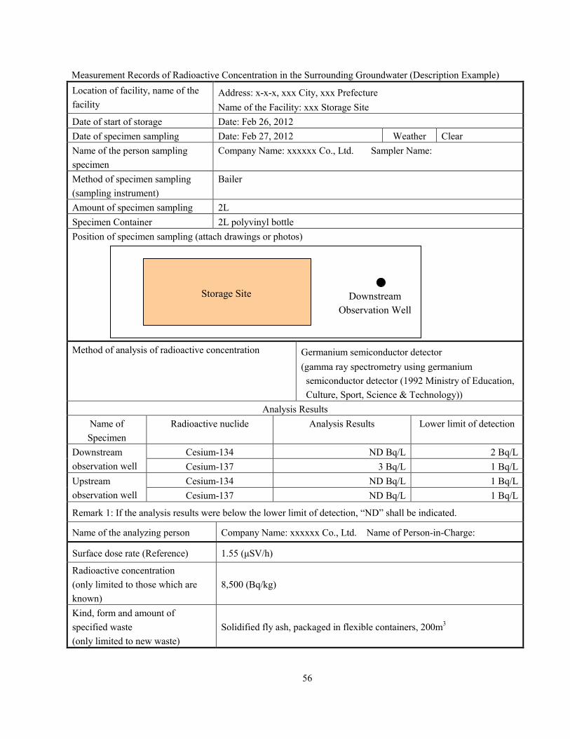
56
Measurement Records of Radioactive Concentration in the Surrounding Groundwater (Description Example)
Location of facility, name of the
facility
Address: x-x-x, xxx City, xxx Prefecture
Name of the Facility: xxx Storage Site
Date of start of storage Date: Feb 26, 2012
Date of specimen sampling Date: Feb 27, 2012 Weather Clear
Name of the person sampling
specimen
Company Name: xxxxxx Co., Ltd. Sampler Name:
Method of specimen sampling
(sampling instrument)
Bailer
Amount of specimen sampling 2L
Specimen Container 2L polyvinyl bottle
Position of specimen sampling (attach drawings or photos)
Method of analysis of radioactive concentration Germanium semiconductor detector
(gamma ray spectrometry using germanium
semiconductor detector (1992 Ministry of Education,
Culture, Sport, Science & Technology))
Analysis Results
Name of
Specimen
Radioactive nuclide Analysis Results Lower limit of detection
Downstream
observation well
Cesium-134 ND Bq/L 2 Bq/L
Cesium-137 3 Bq/L 1 Bq/L
Upstream
observation well
Cesium-134 ND Bq/L 1 Bq/L
Cesium-137 ND Bq/L 1 Bq/L
Remark 1: If the analysis results were below the lower limit of detection, “ND” shall be indicated.
Name of the analyzing person Company Name: xxxxxx Co., Ltd. Name of Person-in-Charge:
Surface dose rate (Reference) 1.55 (μSV/h)
Radioactive concentration
(only limited to those which are
known)
8,500 (Bq/kg)
Kind, form and amount of
specified waste
(only limited to new waste)
Solidified fly ash, packaged in flexible containers, 200m3
Downstream
Observation Well
Storage Site
57
Chapter 7 Burnt Residue, Soot and Dust, Discharged Sludge, Slag from Ash Melting Furnace, Fly Ash
from Ash Melting Furnace
Method to measure radiation concentration of radioactive substances discharged by the
accident in waste (Ministry of the Environment Bulletin No. 107 dated Dec 28, 2011) The methods prescribed by the Minister of the Environment under Article 5 item (iv)
and Article 20 item (iv) of the Special Measures Act Enforcement Ordinance on the
treatment of environmental contamination caused by radioactive substances discharged
by the nuclear plant accident as a result of the Pacific Ocean earthquake which occurred
in the Tohoku region on Mar 11, 2011, shall use the equipment listed in the attachment
for measurement purposes.
Attachment
1. Germanium semiconductor detector
2. NaI (Tl) scintillation spectrometer
3. LaBr3 (Ce) scintillation spectrometer
7.1 Specimen Sampling
Specimen sampling shall be conducted, considering the objective and site and conditions for
representativeness of specimen.
Examples of specimen sampling will be shown below.
· Increment scoop, etc. (Figure 7-1) shall be used for specimen sampling
· In case of piled specimens, sample from at least four isolated points to secure representativeness.
Examples of sampling from piled specimens are shown in Figure 7-2.
· If specimens are flowing on the conveyor, sampling shall be conducted at least four times by certain
intervals during moving of a lot.
· The sampling volume per location shall be based on JIS K 0060 “Sampling Method for Industrial
Waste”. For samples in powder or bulk form, use the volume defined in the table below as a guide
based on the particle size. For sludge, a sample taken with a container that is 100 mL or more in
volume shall be considered a single sample in general.
· Place all four or more samples into one container (a plastic bag with a fastener is acceptable) and
mixed well, dividing into smaller portions where necessary.
· Final sampling amount shall be approximately 500g - 1kg as a guide.
* Under JIS K 0060, it is provided that “3-5 increments will be sufficient for sampling purposes if
the waste formation or treatment process is sufficiently controlled.”

58
Table 7-1: Maximum Particle Size and Size of Increment Sample (Average Volume)
(Source: JIS K 0060 “Sampling Method for Industrial Waste”)
Maximum Particle
Size(mm) 1 5 10 16 22.4 31.5 40 50 71 100 125 150
Average Volume of
Increment(ml) Approx.
16
Approx.
70
Approx.
120
Approx.
180
Approx.
270
Approx.
380
Approx.
730
Approx.
1,600
Approx.
3,700
Approx.
11,000
Approx.
21,000
Approx.
35,000
Reference: When a lot with a maximum particle size of 40mm is sieved with a screen mesh of 40 mm, about
5% of the lot will remain in the sieve. For example, an increment size of approximately 730 mL
on average will be adequate.
Figure 7-1: Increment Scoop
○ shows the increment sampling point.
Figure 7-2: Examples of Sampling Points of Piled Specimens
59
7.2 Management of Measurement Results
Burnt residue, soot and dust, discharged sludge, slag from ash melting furnace, fly ash from ash melting
furnace shall be managed in accordance with the standards depending on the radioactive concentration.
Measurement results shall be retained.
Measurement results shall be recorded and retained for the following items
(1) Address of the facility, name of the facility
(2) Date of specimen sampling
(3) Name of the person sampling specimen
(4) Position of specimen sampling
(5) Method of specimen sampling (sampling instrument)
(6) Amount of specimen sampling
(7) Specimen container
(8) Method of analysis of radioactive concentration
(9) Analysis results
(10) Name of the analyzing person
7.3 Analysis Conditions and Lower Limit of Detection
Analysis of radioactive concentration shall be made in compliance with “Part I: Guidelines for Survey on
Pollution Status.”
In addition to analysis of radioactive concentration, measurement of water content rate shall be made.
Conditions for nuclide analysis by a germanium semiconductor detector (measurement by NaI (Tl)
scintillation spectrometer or LaBr3 (Ce) scintillation spectrometer is possible) are shown in Table 7-2.
Table 7-2: Analysis Conditions
Measurement Specimen
Pre-treatment Specimen Container
Measuring time (Reference)
Lower limit of detection
Remarks
Burnt residue, soot and dust, discharged sludge, slag from ash melting furnace, fly ash from ash melting furnace
None or crushing U-8 Container 1000~2000sec. 10~30 Bq/kg The lower limit of detection fluctuates according to the specimen density. The lower limit of detection of specimen containing radiation will be higher due to the impact of Compton dispersion.
Remark 1: The lower limit of detection shown in the table is a target value. If this is exceeded, change
the analysis conditions and repeat the analysis. However, if a value higher than the lower
limit of detection is obtained, then this lower limit of detection shall not apply.
Remark 2: The analyzed result is reported as it is if it is above the lower limit of detection, and
reported as “ND” if it is less than the lower limit of detection.
Remark 3: When checking for minute radiation concentration in water effluent in a specimen
container, the analysis can also be done using a Marinelli (2L) container.
Remark 4: The analyzed result shall assume the concentration to be in a hydrated state.
60
Remark 5: The analyzed result shall be rounded to 2 significant figures in accordance with Rule B
under JIS Z 8401 “Rounding of Figures”. In addition, the minimum number of digits
displayed shall be up to the number of digits of the lower limit of detection.
Remark 6: The lower limit of detection shall be shown for cesium-134 and cesium-137 respectively.
(Reference)
As a routine management method to determine before measurement whether the designated standards are
satisfied, by measuring the surface dose rate, using a survey meter, a more simplified assumption can be made
if the quantity and properties, etc., of the survey subjects are the same. In such an event, it is necessary that the
results of the radioactive concentration and the surface dose rate shall be accumulated and the coefficient for
assumption shall be determined in advance.
However, please note a simplified assumption cannot replace the actual measurement.
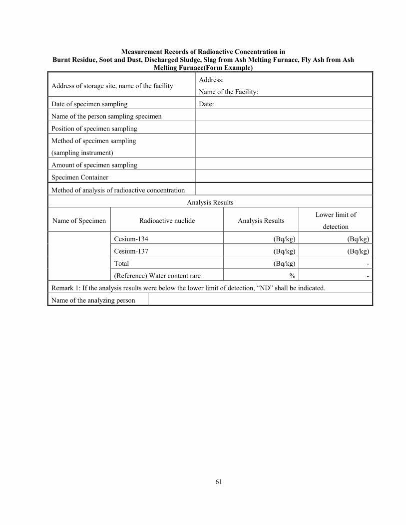
61
Measurement Records of Radioactive Concentration in
Burnt Residue, Soot and Dust, Discharged Sludge, Slag from Ash Melting Furnace, Fly Ash from Ash
Melting Furnace(Form Example)
Address of storage site, name of the facility Address:
Name of the Facility:
Date of specimen sampling Date:
Name of the person sampling specimen
Position of specimen sampling
Method of specimen sampling
(sampling instrument)
Amount of specimen sampling
Specimen Container
Method of analysis of radioactive concentration
Analysis Results
Name of Specimen Radioactive nuclide Analysis Results Lower limit of
detection
Cesium-134 (Bq/kg) (Bq/kg)
Cesium-137 (Bq/kg) (Bq/kg)
Total (Bq/kg) -
(Reference) Water content rare % -
Remark 1: If the analysis results were below the lower limit of detection, “ND” shall be indicated.
Name of the analyzing person
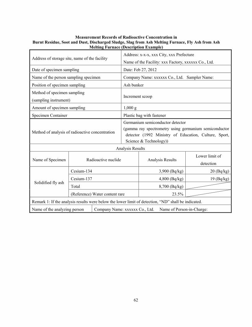
62
Measurement Records of Radioactive Concentration in
Burnt Residue, Soot and Dust, Discharged Sludge, Slag from Ash Melting Furnace, Fly Ash from Ash
Melting Furnace (Description Example)
Address of storage site, name of the facility Address: x-x-x, xxx City, xxx Prefecture
Name of the Facility: xxx Factory, xxxxxx Co., Ltd.
Date of specimen sampling Date: Feb 27, 2012
Name of the person sampling specimen Company Name: xxxxxx Co., Ltd. Sampler Name:
Position of specimen sampling Ash bunker
Method of specimen sampling
(sampling instrument) Increment scoop
Amount of specimen sampling 1,000 g
Specimen Container Plastic bag with fastener
Method of analysis of radioactive concentration
Germanium semiconductor detector
(gamma ray spectrometry using germanium semiconductor
detector (1992 Ministry of Education, Culture, Sport,
Science & Technology))
Analysis Results
Name of Specimen Radioactive nuclide Analysis Results Lower limit of
detection
Solidified fly ash
Cesium-134 3,900 (Bq/kg) 20 (Bq/kg)
Cesium-137 4,800 (Bq/kg) 19 (Bq/kg)
Total 8,700 (Bq/kg)
(Reference) Water content rare 23.5%
Remark 1: If the analysis results were below the lower limit of detection, “ND” shall be indicated.
Name of the analyzing person Company Name: xxxxxx Co., Ltd. Name of Person-in-Charge:

63
Chapter 8 Elution Amount
Requirements of specified waste eluting low quantities of radioactive substances
discharged by the accident when there is infiltration of rainwater and other water (Ministry
of the Environment Bulletin No. 3 dated Jan 13, 2012)
Article 1
For test solutions pertaining to the specified waste concerned that have been prepared in
accordance with the method set forth in JIS K 0058-1, the radiation concentration for cesium-137
as measured by the equipment given separately in the attachment must be 150 Bq/L or less as
prescribed by the Minister of the Environment under Article 26 paragraph (2) item (ii) (e) of the
Special Measures Act Enforcement Ordinance on the treatment of environmental contamination
caused by radioactive substances discharged by the nuclear plant accident as a result of the
Pacific Ocean earthquake which occurred in the Tohoku region on Mar 11, 2011.
Article 2 Omitted
Attachment
1 Germanium semiconductor detector
2 NaI (Tl) scintillation spectrometer
3 LaBr3 (Ce) scintillation spectrometer
Requirements of waste that poses no risk of contaminating public water areas and
groundwater with radioactive substances discharged by the accident (Ministry of the
Environment Bulletin No. 6 dated Jan 27, 2012)
For test solutions pertaining to the waste concerned that have been prepared in accordance with
the method set forth in JIS K 0058-1, no cesium-134 and cesium-137 must be detected when
measured using a germanium semiconductor detector as prescribed by the Minister of the
Environment under Article 29 item (iii) (d) (1) of the Special Measures Act Enforcement
Ordinance on the treatment of environmental contamination caused by radioactive substances
discharged by the nuclear plant accident as a result of the Pacific Ocean earthquake which
occurred in the Tohoku region on Mar 11, 2011.
Requirements of specified waste complying with the standards that poses no risk of
contaminating public water areas and groundwater (Ministry of the Environment Bulletin
No. 169 dated Dec 25, 2012)
Article1 - Article 2 Omitted
Article 3
For test solutions pertaining to the waste concerned that have been prepared in
accordance with the method set forth in JIS K 0058-1, no cesium-134 and cesium-137
must be detected when measured using a germanium semiconductor detector.
Requirements of specified industrial waste that poses no risk of contaminating public
water areas and groundwater with radioactive substances discharged by the accident
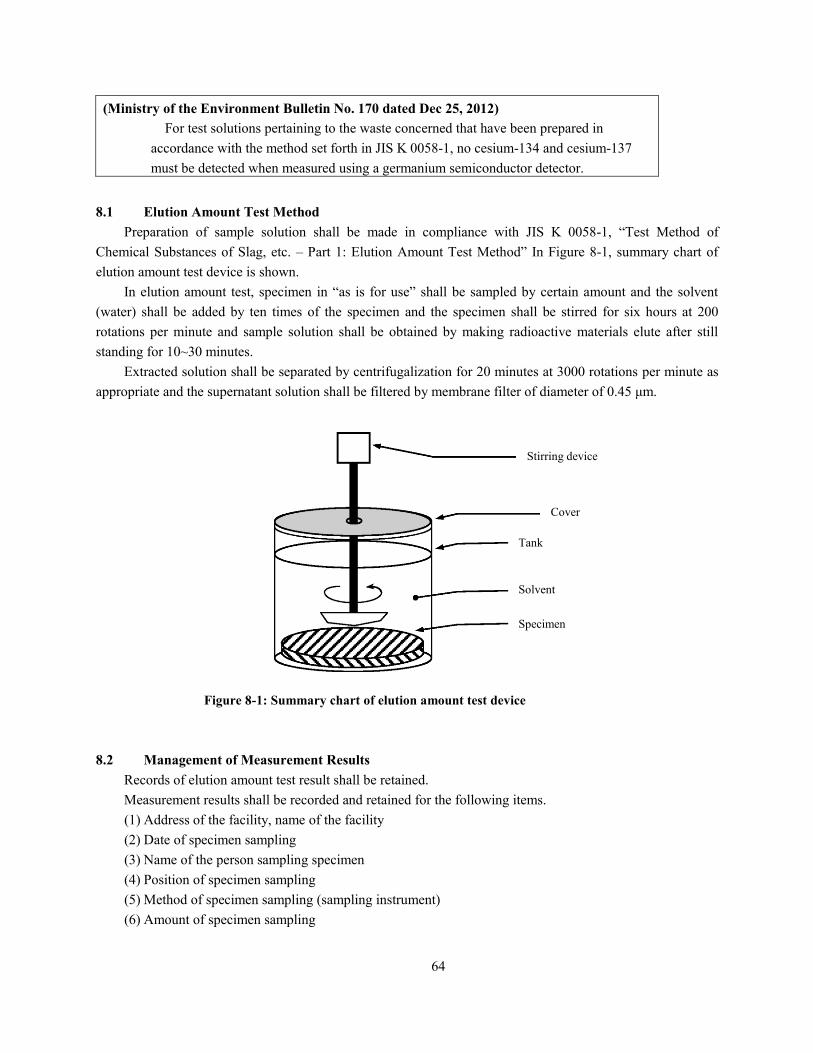
64
(Ministry of the Environment Bulletin No. 170 dated Dec 25, 2012)
For test solutions pertaining to the waste concerned that have been prepared in
accordance with the method set forth in JIS K 0058-1, no cesium-134 and cesium-137
must be detected when measured using a germanium semiconductor detector.
8.1 Elution Amount Test Method
Preparation of sample solution shall be made in compliance with JIS K 0058-1, “Test Method of
Chemical Substances of Slag, etc. – Part 1: Elution Amount Test Method” In Figure 8-1, summary chart of
elution amount test device is shown.
In elution amount test, specimen in “as is for use” shall be sampled by certain amount and the solvent
(water) shall be added by ten times of the specimen and the specimen shall be stirred for six hours at 200
rotations per minute and sample solution shall be obtained by making radioactive materials elute after still
standing for 10~30 minutes.
Extracted solution shall be separated by centrifugalization for 20 minutes at 3000 rotations per minute as
appropriate and the supernatant solution shall be filtered by membrane filter of diameter of 0.45 μm.
Figure 8-1: Summary chart of elution amount test device
8.2 Management of Measurement Results
Records of elution amount test result shall be retained.
Measurement results shall be recorded and retained for the following items.
(1) Address of the facility, name of the facility
(2) Date of specimen sampling
(3) Name of the person sampling specimen
(4) Position of specimen sampling
(5) Method of specimen sampling (sampling instrument)
(6) Amount of specimen sampling
Stirring device
Cover
Tank
Solvent
Specimen
65
(7) Specimen Container
(8) Method of elution amount test
(9) Method of analysis of radioactive concentration
(10) Analysis results
(11) Name of the analyzing person
8.3 Analysis Conditions and Lower Limit of Detection
Analysis of radioactive concentration shall be made in compliance with “γ-rays Spectrometry by
Germanium Semiconductor Detector (1992, Ministry of Education, Culture, Sports, Science and Technology)
Analysis conditions for nuclide analysis by a germanium semiconductor detector (measurement by NaI
(Tl) scintillation spectrometer or LaBr3 (Ce) scintillation spectrometer is also possible: Limited to the case in
which the Ministry of the Environment Bulletin No. 3 dated Jan 13, 2012, applies) are shown in Table 8-1.
Table 8-1: Analysis Conditions
Measurement
Specimen Pre-treatment Specimen Container
Measuring time
(Reference) Lower limit of detection
Elution Liquid None U-8 Container 1000~2000sec. 10~20Bq/L
Remark 1: The lower limit of detection shown in the table is a target value. If this is exceeded, change
the analysis conditions and repeat the analysis. However, if a value higher than the lower
limit of detection is obtained, then this lower limit of detection shall not apply.
Remark 2: The analyzed result is reported as it is if it is above the lower limit of detection, and
reported as “ND” if it is less than the lower limit of detection.
Remark 3: When checking for minute radiation concentration in water effluent in a specimen
container, the analysis can also be done using a Marinelli (2L) container.
Remark 4: The analyzed result shall be rounded to 2 significant figures in accordance with Rule B
under JIS Z 8401 “Rounding of Figures”. In addition, the minimum number of digits
displayed shall be up to the number of digits of the lower limit of detection.
Remark 5: The lower limit of detection shall be shown for cesium-134 and cesium-137 respectively.
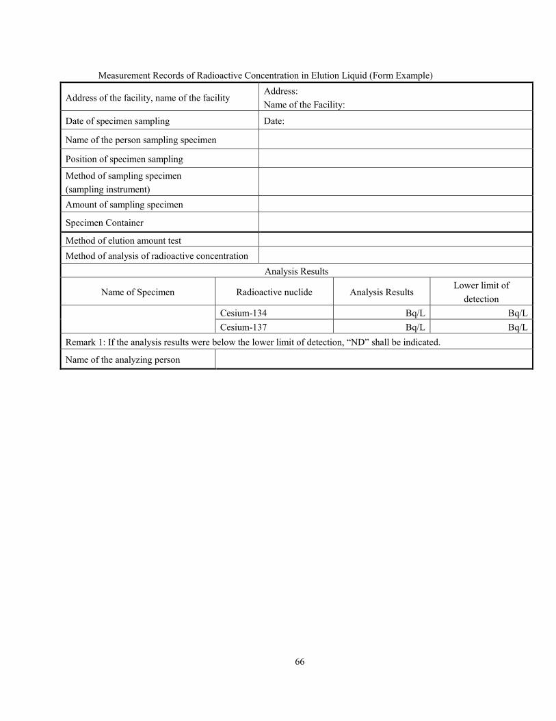
66
Measurement Records of Radioactive Concentration in Elution Liquid (Form Example)
Address of the facility, name of the facility Address:
Name of the Facility:
Date of specimen sampling Date:
Name of the person sampling specimen
Position of specimen sampling
Method of sampling specimen
(sampling instrument)
Amount of sampling specimen
Specimen Container
Method of elution amount test
Method of analysis of radioactive concentration
Analysis Results
Name of Specimen Radioactive nuclide Analysis Results Lower limit of
detection
Cesium-134 Bq/L Bq/L
Cesium-137 Bq/L Bq/L
Remark 1: If the analysis results were below the lower limit of detection, “ND” shall be indicated.
Name of the analyzing person
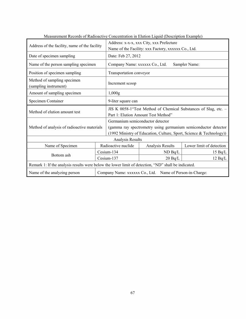
67
Measurement Records of Radioactive Concentration in Elution Liquid (Description Example)
Address of the facility, name of the facility Address: x-x-x, xxx City, xxx Prefecture
Name of the Facility: xxx Factory, xxxxxx Co., Ltd.
Date of specimen sampling Date: Feb 27, 2012
Name of the person sampling specimen Company Name: xxxxxx Co., Ltd. Sampler Name:
Position of specimen sampling Transportation conveyor
Method of sampling specimen
(sampling instrument) Increment scoop
Amount of sampling specimen 1,000g
Specimen Container 9-liter square can
Method of elution amount test JIS K 0058-1“Test Method of Chemical Substances of Slag, etc. –
Part 1: Elution Amount Test Method”
Method of analysis of radioactive materials
Germanium semiconductor detector
(gamma ray spectrometry using germanium semiconductor detector
(1992 Ministry of Education, Culture, Sport, Science & Technology))
Analysis Results
Name of Specimen Radioactive nuclide Analysis Results Lower limit of detection
Bottom ash Cesium-134 ND Bq/L 15 Bq/L
Cesium-137 20 Bq/L 12 Bq/L
Remark 1: If the analysis results were below the lower limit of detection, “ND” shall be indicated.
Name of the analyzing person Company Name: xxxxxx Co., Ltd. Name of Person-in-Charge:

68
Chapter 9 Cited Standards, etc.
· Measurement Method of Spectrum of γ-rays in the Air (1990, Ministry of Education, Culture, Sports,
Science and Technology)
· Guidelines for Monitoring Environmental Radiation in Case of Emergency (June 1984, Nuclear Safety
Commission)
· Provisional Manual of Radiation Survey and Measurement Method of Waste, etc. (November 11,
2011, Study Group of Survey and Measurement Method of Waste, etc.)
· “γ-rays Spectrometry by Germanium Semiconductor Detector (1992, Ministry of Education, Culture,
Sports, Science and Technology)
· JIS Z 4511(2005) Calibration method for exposure meters, air kerma meters, air absorbed
dose meters and dose equivalent meters
· JIS Z 4333(2006) Dose equivalent rate survey meter for X-ray and gamma ray
· JIS Z 8808 (1995)
· JIS K 0060 (1992) Sampling Method of Industrial Waste
· JIS K 0058-1 “Test Method of Chemical Substances of Slag, etc. – Part 1: Elution Amount Test
Method”
· Technical Matters concerning Sampling, etc., of Sludge containing Radioactive Cesium (23 Sho’an
No. 1939, June 27, 2011)
· On Treatment of Waste which might have been contaminated with Radioactive Materials in Municipal
Solid Waste Treatment Facilities (August 29, 2011, Ministry of the Environment)
· Method to measure the radiation level as prescribed by the Minister of the Environment (Ministry of
the Environment Bulletin No. 110 dated Dec 28, 2011)
· Method to measure radiation concentration of radioactive substances discharged by the accident in
waste (Ministry of the Environment Bulletin No. 107 dated Dec 28, 2011)
· Method to measure concentration of radioactive substances discharged by the accident in the exhaust
gas when exhaust gas generated during disposal is discharged (Ministry of the Environment Bulletin
No. 111 dated Dec 28, 2011)
· Method to measure concentration of radioactive substances discharged by the accident in the final
effluent when wastewater generated during disposal is discharged (Ministry of the Environment
Bulletin No. 112 dated Dec 28, 2011)
· Method to measure concentration of radioactive substances discharged by the accident pertaining to
water quality inspection of groundwater as prescribed under Article 26 paragraph (1) item (iii) (a) of
the Special Measures Act Enforcement Ordinance on the treatment of environmental contamination
caused by radioactive substances discharged by the nuclear plant accident as a result of the Pacific
Ocean earthquake which occurred in the Tohoku region on Mar 11, 2011 (Ministry of the
Environment Bulletin No. 113 dated Dec 28, 2011)
· Method to measure concentration of radioactive substances discharged by the accident pertaining
to water quality inspection of final effluent as prescribed under Article 26 paragraph (2) item (iv) (c)
of the Special Measures Act Enforcement Ordinance on the treatment of environmental contamination
caused by radioactive substances discharged by the nuclear plant accident as a result of the Pacific

69
Ocean earthquake which occurred in the Tohoku region on Mar 11, 2011 (Ministry of the
Environment Bulletin No. 114 dated Dec 28, 2011)
· Method to measure concentration of radioactive substances discharged by the accident pertaining
to water quality inspection of groundwater as prescribed under Article 26 paragraph (4) item (ii) (a)
of the Special Measures Act Enforcement Ordinance on the treatment of environmental contamination
caused by radioactive substances discharged by the nuclear plant accident as a result of the Pacific
Ocean earthquake which occurred in the Tohoku region on Mar 11, 2011 (Ministry of the
Environment Bulletin No. 115 dated Dec 28, 2011)
· Method to measure concentration of radioactive substances discharged by the accident pertaining
to water quality inspection of permeating water as prescribed under Article 26 paragraph (4) item
(ii) (c) of the Special Measures Act Enforcement Ordinance on the treatment of environmental
contamination caused by radioactive substances discharged by the nuclear plant accident as a result of
the Pacific Ocean earthquake which occurred in the Tohoku region on Mar 11, 2011 (Ministry of the
Environment Bulletin No. 116 dated Dec 28, 2011)
· Requirements of specified waste eluding low quantities of radioactive substances discharged by the
accident when there is infiltration of rainwater and other water as prescribed under Article 26
paragraph (2) item (ii) (e) of the Special Measures Act Enforcement Ordinance on the treatment of
environmental contamination caused by radioactive substances discharged by the nuclear plant
accident as a result of the Pacific Ocean earthquake which occurred in the Tohoku region on Mar 11,
2011 (Ministry of the Environment Bulletin No. 3 dated Jan 13, 2012)
· Requirements of waste that poses no risk of contaminating public water areas and groundwater with
radioactive substances discharged by the accident (Ministry of the Environment Bulletin No. 6 dated
Jan 27, 2012)
· Compliance requirements of specified waste that poses no risk of contaminating public water areas
and groundwater (Ministry of the Environment Bulletin No. 169 dated Dec 25, 2012)
· Requirements of specified industrial waste that poses no risk of contaminating public water areas and
groundwater with radioactive substances discharged by the accident (Ministry of the Environment
Bulletin No. 170 dated Dec 25, 2012)