gujarat energy transmission corporation ltd. office/01... · gujarat energy transmission...
TRANSCRIPT

GETCO/E/01TS CT6 PT7 Metering/R7/May 12
Sign and Seal of Bidder Page No. 1 of 33
GUJARAT ENERGY TRANSMISSION
CORPORATION LTD. SARDAR PATEL VIDYUT BHAVAN,
RACE COURSE, BARODA – 390 007.
TECHNICAL SPECIFICATIONS
FOR
132 kV INSTRUMENT TRANSFORMERS
GETCO/E/01TS CT6 PT7 Metering/R7/May 12

GETCO/E/01TS CT6 PT7 Metering/R7/May 12
Sign and Seal of Bidder Page No. 2 of 33
SPECIAL INSTRUCTIONS TO BIDDER Please read following instructions carefully before submitting your bid. 1. All the drawings, i.e. elevation, side view, plan, cross sectional view etc., in
AutoCAD format and manuals in PDF format, for offered item shall be submitted. Also the hard copies as per specification shall be submitted.
2. The bidder shall submit Quality Assurance Plan with the technical bid. 3. The bidder shall have to submit all the required type test reports for the offered
item. Bid without type tests will not be considered for evaluation. 4. The bidder must fill up all the points of GTP for offered item/s. Instead of
indicating “refer drawing, or as per IS/IEC”, the exact value/s must be filled in. 5. All the points other than GTP, which are asked to confirm in technical
specifications must be submitted separately with the bid. 6. The bidder is required to impart training in view of manufacture, assembly,
erection, operation and maintenance for offered item, at his works, to the person/s identified by GETCO, in the event of an order, free of cost. The cost of logistics will be bear by GETCO.
7. Please note that the evaluation will be carried out on the strength of content of
bid only. No further correspondence will be made. 8. The bidder shall bring out all the technical deviation/s only at the specified
annexure.

GETCO/E/01TS CT6 PT7 Metering/R7/May 12
Sign and Seal of Bidder Page No. 3 of 33
QUALIFYING REQUIREMENT DATA
(For Supply)
Bidder to satisfy all the following requirements. 1) The bidder shall be Original Equipment Manufacturer (OEM).
The offered equipment have to be designed, manufactured and tested as per relevant IS/IEC with latest amendments.
2) The minimum requirement of manufacturing capacity of offered
type, size and rating of equipment shall be SEVEN times tender/ bid quantity. The bidder should indicate manufacturing capacity by submitting latest updated certificate of a Chartered Engineer (CE).
3) Equipment proposed shall be of similar or higher rating and in
service for a minimum period of THREE (3) years and satisfactory performance certificate in respect of this is to be available and submitted.
4) The bidder should clearly indicate the quantity and Single Value
Contract executed during last FIVE (5) years, for the offered equipment. Bidder should have executed one single contract during last five years for the quantity equivalent to tender / bid.
The details are to be submitted in following format, Sr. No
ITEMS SUPPLIED TO
ORDER REFERENCE No. &
DATE
ITEMS QUANTITY
ORDER FULLY
EXECUTED. YES/NO
STATUS, IF ORDER UNDER
EXECUTION
REMARK
5) Equipment offered shall have Type Test Certificates from
accredited laboratory (accredited based on ISO/IEC Guide 25 / 17025 or EN 45001 by the National accreditation body of the country where laboratory is located), as per IEC / IS / technical specification. The type test reports shall not be older than FIVE years and shall be valid up to expiry of validity of offer.

GETCO/E/01TS CT6 PT7 Metering/R7/May 12
Sign and Seal of Bidder Page No. 4 of 33
GENERAL TECHNICAL SPECIFICATION
1.1 SCOPE :
1.1.1 This section covers the design, manufacture, assembly, testing at the
manufacturer’s, supply and delivery of outdoor, Live/Dead tank type, oil
impregnated paper, single phase Instrument Transformer, along with
supporting structure as detailed in the enclosed schedule of requirement for
relaying and metering services in three phase solidly ground system.
1.1.2 The bidder shall give assurance for trouble free and maintenance free
performance for a period of 60 (sixty) months from the date of receipt at store,
during which period, the CTs shall be repaired/reconditioned/replace free of
cost immediately in case of any trouble. Therefore, the bidder shall ensure that
sealing of Instrument Transformer is properly achieved.
1.2 STANDARDS:
1.2.1 CURRENT/VOLTAGE TRANSFORMERS:
Sr.
No.
Standard No. Title
1 IS:2165 Insulation co-ordination for equipment of 100 KV and above
2 IS:2705 (I to IV) Instrument Transformers
3 IS:2099 High voltage porcelain bushings
4 IS:3347 Dimensions of porcelain transformer bushings
5 IS:2071 Method of high voltage testing
6 IS:335 Insulating oil for transformers and switchgears
7 IS:2147 Degree of protection provided by enclosures for low voltage
switchgear and control.
8 IEC-60044-1 & 2 Instrument Transformers
9 IEC-186 Instrument Transformers (VT)
10 IEC-270 Partial discharge measurement
11 IEC-44(4) Instrument transformer measurement of PDs
12 IEC-171 Insulation co-ordination
13 IEC-60 High voltage testing techniques
14 IEC-8263 Method for RIV test on high voltage insulators
15 -- Indian Electricity Rules 1956
16 IS-3156 (Part I to
IV)
Voltage Transformer

GETCO/E/01TS CT6 PT7 Metering/R7/May 12
Sign and Seal of Bidder Page No. 5 of 33
1.2.2 Equipment meeting with the requirement of other authoritative Standards, which
ensure equal or better performance than the standards mentioned above, shall also
be considered. When the equipments offered by the Bidder conforms to other
standards, salient points of difference between standard adopted and the standards
specified in this specification shall be clearly brought out in the relevant schedule.
Four copies of such standards with authentic translation in English shall be
furnished along with the offer.
1.2.3 The Instrument Transformers covered by this specification shall comply with the
requirement of the latest edition of IEC Publication No. 60044-1 & IS: 2705 for CT and IEC Publication No. 60044-2 & IS: 3156 (Parts – I to III as amended up
to date) for PT, but the Instrument Transformers for the accuracy class ‘PS’ shall
confirm to Part - IV of IS : 2705 & IS:3156 respectively except where specified
otherwise in the specification.
1.3 DRAWINGS :
1.3.1 Drawing incorporating the following particulars shall be submitted by each bidder
with the bid for the purpose of preliminary study.
(a) General arrangement and assembly drawings of equipment.
(b) Graphs showing the performance of equipment in regard to magnetizing
characteristics, ratio and phase angle error curves and composite error
curves.
(c) Arrangement of secondary terminal equipment and including of duplicate
terminal connection arrangement.
(d) Supporting structure drawing (If in the scope of bidder)
1.3.2 The Bidder shall submit to the Purchaser, the following drawings for the approval
of the Purchaser. The schedule shall be prepared so as to ensure delivery
commitments made in the contract.
(a) Outline dimensional drawing plan, elevation, end-view dimension,
shipping dimensions etc. of the CTs.
(b) Dimensional drawing of CT along with details of clamp and terminal
connectors.
(c) Complete mounting arrangement and structure drawing of CTs
indicating cable entry clearly.
(d) Cross section view of the Instrument Transformers.

GETCO/E/01TS CT6 PT7 Metering/R7/May 12
Sign and Seal of Bidder Page No. 6 of 33
(e) Winding diagram with polarity marks.
(f) Magnetisation curves.
(g) Diagram plate, electrical connections of component parts of the CTs
and terminal arrangement of secondary terminal box.
(h) Name and rating plate as per Indian Standard 2705.
(i) Drawing is necessary for design and fabrication of supporting
structure (structures are included in the scope of supply).
1.3.3 The Bidder may submit any other drawing found necessary in addition to these
stated above.
1.4 TYPE AND RATING :
1.4.1 The Instrument Transformers shall be of outdoor Live / Dead tank type, oil
impregnated paper, single phase, 50 Hz, oil immersed, self cooled and suitable
for the services indicated and for operation in the climatic conditions specified
without protection from sun, rain and dust. The Instrument Transformer shall be
complete in all respects and shall conform to the modern practice of design and
manufacture.
1.4.2 The core shall be high grade non-ageing, electrical, silicon laminated steel of low
hysterisis loss and high permeability to ensure high accuracy at both normal and
over currents. The core material used in case of metering cores shall be stated in
the tender.
1.4.3 Instrument Transformers shall be provided with prismatic type oil sight window
with green fluorescent ball of non oil reacting material, at suitable
location so that the oil level is clearly visible with naked eye to an observer
standing at ground level. If metal bellow is used for above purpose, a ground glass
window shall also be provided to monitor the position of the metal bellow.
For compensation of variation in volume the oil due to temperature variation
nitrogen cushion or suitable steel below shall be used. Rubber diaphragms shall
not be permitted for this purpose.
Instrument transformer shall be hermetically sealed to climatic breathing and entering air & moisture in the tank, either by providing stainless steel bellow or by nitrogen cushioning. All parts of bellow shall be stainless steel only. In case of instrument transformer without stainless steel bellow, but sealed by nitrogen cushion, the pressure relief valve shall be provided so that overpressure caused by internal faults can be instantaneously relieved and bursting of unit is avoided.

GETCO/E/01TS CT6 PT7 Metering/R7/May 12
Sign and Seal of Bidder Page No. 7 of 33
The pressure relief valve shall comply as follow: a) It shall be either of stainless steel or brass material. b) Spring used shall be of non magnetic stainless steel. c) It shall conform to relevant IS/IEC standards. d) It shall be suitably calibrated for the maximum allowed pressure.
Bidder shall ensure that during any of the acceptance tests PRV shall not operate.
e) Its satisfactory operation shall be offered during stage inspection. f) It will be treated as major bought out item hence; necessary test
report from vendor shall be submitted.
1.4.4 The Instrument Transformers core to be used for metering and instrumentation
shall be accuracy class specified or appropriate class suitable for commercial and
industrial metering as per the standard adopted. The saturation factor of this core
shall be low enough as not to cause any damage to the measuring instruments in
the event of maximum short circuit current.
1.5 Windings :
1.5.1 The rating of the secondary winding shall be as specified in the specification. The
secondary terminals shall be brought out in a compartment for easy access. The
secondary terminals shall be provided with the shorting arrangements. The
secondary taps shall be adequately reinforced to withstand the normal handling
without damage. All the secondary winding will be loaded simultaneously.
1.5.2 Primary & Secondary winding :
There are three ratios specified in tender specification. The change in ratio
shall be by secondary taps (winding). Selection of ratio on each core shall be
independent of the ratio of other core. The guaranteed burden, knee point
voltage, winding resistance and magnetizing current as specified for each ratio
will have to adhere too. The secondary taps shall be adequately rain forced to
withstand normal handling without damages. 1.5.2 Primary winding shall be made out of high conductivity copper or
aluminum, Conductors used for the primary winding shall be rigid or housed in rigid metallic shell. Unavoidable joints in the primary winding shall be welded type. The details of such welded joints shall be indicated in the drawings submitted with the offer. For primary winding current density shall not exceed 1.65 A/sq. mm for copper and 1.05 A/Sq.mm for aluminum, if made out of solid conductor .If the primary conductor is made out of tubular conductor (pipe), the joints in the bend portion shall be allowed. The welding type quality and extent shall be as per relevant ISS or other equivalent standard.
GETCO/E/01TS CT6 PT7 Metering/R7/May 12
Sign and Seal of Bidder Page No. 8 of 33
The design density for short circuit current as well as conductivity of the metal used for primary winding shall meet the requirement of IS:2705. The Bidder shall in his offer furnish detailed calculations for selection of winding cross-sections.
1.5.3 Primary and secondary windings shall have continuous thermal rating, as
specified, for all ratios. It shall be possible to select the CT ratio of core,
different than and independent of the CT ratio of another core of the same CT.
1.5.4 The outer surface of metal tank shall be Hot Dip Galvanized, the inner
portion shall be painted with oil resistive, insoluble paint or hot dip galvanised. The GETCO reserves right for stage inspection during manufacturing process of tank / CT. The galvanising shall be as per applicable standard IS:2629 and minimum thickness of zinc coating shall be 610 gm/sqmt.
1.6 Terminal Box :
1.6.1 All secondary terminals shall be brought out in a weather proof compartment
of one side of each Instrument Transformer for easy access. A terminal board
shall have arrangement for series parallel connections, shorting of secondary
terminals and grounding of PT primary terminals. A cable box along with
necessary glands for receiving control cables suitable for mounting on the
bottom plate of the terminal box shall be included in the scope of supply. The
size of the cable gland will be intimated to the successful tenderer. A door with
locking arrangement shall be provided on the front of the terminal box so as to
permit easy access to the secondary terminals. The door shall have suitable
arrangement to check ingress of moisture into the terminal box. The secondary terminal box shall comply with degree of protection IP-55 standards and type test report shall be submitted with the technical bid.
1.6.2 A duplicate set of secondary terminals connected through a suitable link shall
be provided in the terminal box. One set shall be connected to the terminal
secondary leads while the other one shall be connected to external cable leads.
This type of arrangement is essential to prevent undue pressure to internal
leads and failure of studs while connecting the external cable leads to the
secondary terminals, as both the terminals will be independent for their
connections. 20 % of terminals shall be provided as spare.
1.7 Temperature Rise :
1.7.1 The voltage transformers shall be designed to limit the temperature rise of
winding and other parts as specified in the Indian Standard, when corrected for
the difference between the temperature prevailing and site and temperature
specified by the Indian Standard. The temperature rise at 1.2 times and rated
primary voltage when applied continuously at rated frequency and at rated
burden shall not exceed the limits specified above and the temperature rise at
GETCO/E/01TS CT6 PT7 Metering/R7/May 12
Sign and Seal of Bidder Page No. 9 of 33
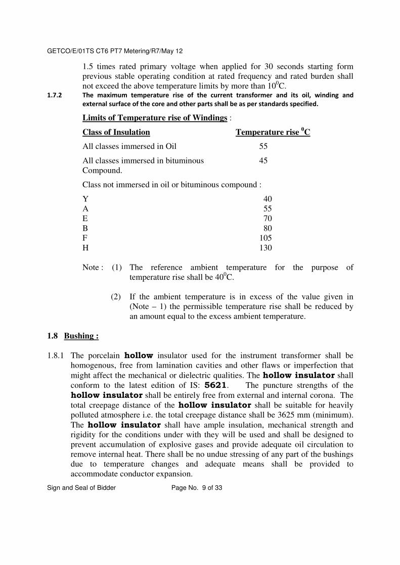
1.5 times rated primary voltage when applied for 30 seconds starting form
previous stable operating condition at rated frequency and rated burden shall
not exceed the above temperature limits by more than 100C.
1.7.2 The maximum temperature rise of the current transformer and its oil, winding and
external surface of the core and other parts shall be as per standards specified.
Limits of Temperature rise of Windings :
Class of Insulation Temperature rise 0C
All classes immersed in Oil 55
All classes immersed in bituminous 45
Compound.
Class not immersed in oil or bituminous compound :
Y 40
A 55
E 70
B 80
F 105
H 130
Note : (1) The reference ambient temperature for the purpose of
temperature rise shall be 400C.
(2) If the ambient temperature is in excess of the value given in
(Note – 1) the permissible temperature rise shall be reduced by
an amount equal to the excess ambient temperature.
1.8 Bushing :
1.8.1 The porcelain hollow insulator used for the instrument transformer shall be
homogenous, free from lamination cavities and other flaws or imperfection that
might affect the mechanical or dielectric qualities. The hollow insulator shall
conform to the latest edition of IS: 5621. The puncture strengths of the
hollow insulator shall be entirely free from external and internal corona. The
total creepage distance of the hollow insulator shall be suitable for heavily
polluted atmosphere i.e. the total creepage distance shall be 3625 mm (minimum).
The hollow insulator shall have ample insulation, mechanical strength and
rigidity for the conditions under with they will be used and shall be designed to
prevent accumulation of explosive gases and provide adequate oil circulation to
remove internal heat. There shall be no undue stressing of any part of the bushings
due to temperature changes and adequate means shall be provided to
accommodate conductor expansion.

GETCO/E/01TS CT6 PT7 Metering/R7/May 12
Sign and Seal of Bidder Page No. 10 of 33
1.8.2 The hollow insulator shall be so designed that when operating at highest
system voltage specified, there will be no electric discharge between the
conductors, and hollow insulator. No corrosion or injury shall be causes to
conductor insulation or supports by the formation of substances produced by
chemical action. The insulation of hollow insulator shall be co-ordinated with
that of the instrument transformer such that the flashover, if any, will occur only
externally to the Instrument Transformer. The hollow insulator shall not cause
radio interference when operated at rated voltage. The specification of the bushing
shall be stated in the tender.
1.9 Insulation Oil :
1.9.1 The quantity of insulating for the first filling and the complete specification of the
oil shall be stated in tender. The oil shall comply in all respects with the provisions
of the latest edition of IS:335 or IEC Publication No. 296 (as amended upto date).
The oil shall have the following main characteristics for equivalent. (The
requirement indicated is determined in accordance with the test methods adopted
by IS :335).
Sr.
No.
Characteristics Requirements Method of Test
1 Appearance The oil shall be
clear & transparent
& free from
suspended matter
or sediment.
A representative sample of oil
shall be examined in a 100mm
thick layer, at ambient
temperature of equivalent
authoritative standard.
2 Density at 270C Max. 0-89g / cm
3
IS:1448 (P-16) 1967 or
equivalent Authoritative
standard.
3 Kinematics viscosity at
270C Max.
27 CST IS : 1448 (P-25), 1960 or
equivalent Authoritative
standard.
4 Interfacial tension at
270C Min.
0.04 N / m IS : 6104 – 1971 or equivalent
Authoritative standard.
5 Flash point pensky
marten (closed) Min.
140 0C IS : 1448 (P-21) 1970 or
equivalent Authoritative
standard.
6 Four point max. - 10 0C IS : 1448 (P-10) 1970 or
equivalent Authoritative
standard.
7 Neutralisation value 0.03Mg/KOH/g IS:335-1972,Appendix-A or

GETCO/E/01TS CT6 PT7 Metering/R7/May 12
Sign and Seal of Bidder Page No. 11 of 33
(Total acidity) max. equivalent Authoritative
standard.
8 Corrosive sulphur (in
terms of classification
of copper strip)
Non – corrosive IS:335-1972,AppendixB. or
equivalent Authoritative
standard.
9 Electric strength
(break-down voltage)
Min.
a) New untreated oil.
b) After treatment
30KV (rms). If the
above value is not
attained, the oil
shall be treated.
50 KV (rms.)
IS : 6792 – 1972 or equivalent
Authoritative standard.
10 Dielectric dissipation
factor (tanδ) at 900C
Max.
0.002 IS : 6262 – 1971 or equivalent
Authoritative standard.
11 Specific resistance
(resistivity)
a) At 90 0C Min
b) At 27 0C Min.
35 x 1212
ohm / cm
1500 x 10012
Ohm
IS : 6103 – 1971 or equivalent
Authoritative standard
12 Oxidation stability
a) Neutralisation
value after
oxidation max.
b) Total sludge
after oxidation
Max.
0.40 mg / KOH / g
0.10 percent by
weight.
IS:335–1972, Appendix-C. or
equivalent Authoritative
standard.
13 Ageing characteristic
after accelerated aging
a) Specific resistance
(Resistivity).
i) At 270C Min.
ii) At 900C Min.
b) Dielectric dissipation
factor (tan6) at 900C
Max.
c) Total slug acidity %
by weight.
d) Total slug value%
by weight.
2.5 x 10¹²
ohm/cm.
0.2 x 10¹²
ohm/cm.
0.2
0.05 max. mg.
KOH/G
0.05
IS : 6103 – 1971
IS : 6262 – 1971
IS:1448 – 1967
14 Water content max. 50 ppm. IS : 2362 – 1963 or equivalent
Authoritative standard.
GETCO/E/01TS CT6 PT7 Metering/R7/May 12
Sign and Seal of Bidder Page No. 12 of 33
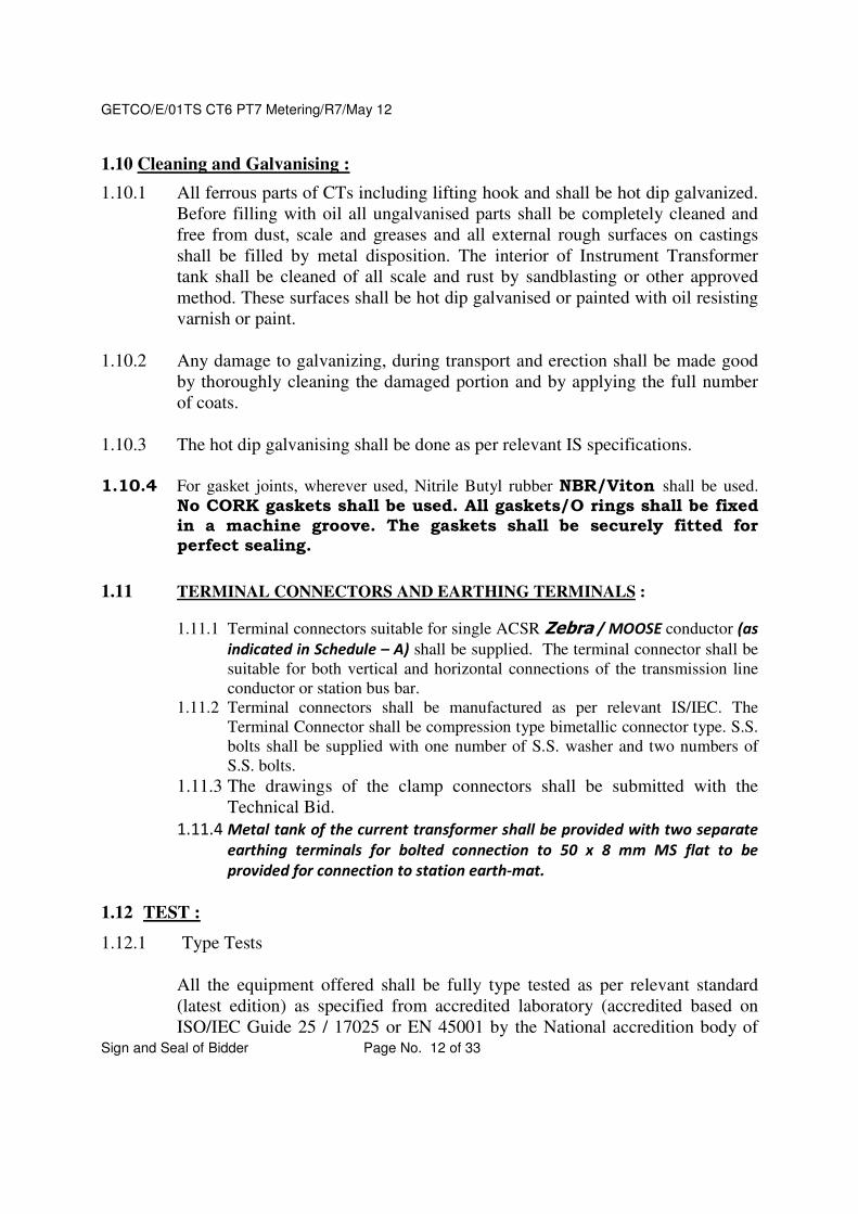
1.10 Cleaning and Galvanising :
1.10.1 All ferrous parts of CTs including lifting hook and shall be hot dip galvanized.
Before filling with oil all ungalvanised parts shall be completely cleaned and
free from dust, scale and greases and all external rough surfaces on castings
shall be filled by metal disposition. The interior of Instrument Transformer
tank shall be cleaned of all scale and rust by sandblasting or other approved
method. These surfaces shall be hot dip galvanised or painted with oil resisting
varnish or paint.
1.10.2 Any damage to galvanizing, during transport and erection shall be made good
by thoroughly cleaning the damaged portion and by applying the full number
of coats.
1.10.3 The hot dip galvanising shall be done as per relevant IS specifications.
1.10.4 For gasket joints, wherever used, Nitrile Butyl rubber NBR/Viton shall be used.
No CORK gaskets shall be used. All gaskets/O rings shall be fixed in a machine groove. The gaskets shall be securely fitted for perfect sealing.
1.11 TERMINAL CONNECTORS AND EARTHING TERMINALS :
1.11.1 Terminal connectors suitable for single ACSR Zebra / MOOSE conductor (as
indicated in Schedule – A) shall be supplied. The terminal connector shall be
suitable for both vertical and horizontal connections of the transmission line
conductor or station bus bar.
1.11.2 Terminal connectors shall be manufactured as per relevant IS/IEC. The
Terminal Connector shall be compression type bimetallic connector type. S.S.
bolts shall be supplied with one number of S.S. washer and two numbers of
S.S. bolts.
1.11.3 The drawings of the clamp connectors shall be submitted with the
Technical Bid.
1.11.4 Metal tank of the current transformer shall be provided with two separate
earthing terminals for bolted connection to 50 x 8 mm MS flat to be
provided for connection to station earth-mat.
1.12 TEST :
1.12.1 Type Tests
All the equipment offered shall be fully type tested as per relevant standard
(latest edition) as specified from accredited laboratory (accredited based on
ISO/IEC Guide 25 / 17025 or EN 45001 by the National accredition body of

GETCO/E/01TS CT6 PT7 Metering/R7/May 12
Sign and Seal of Bidder Page No. 13 of 33
the country where laboratory is located), as per IEC / IS / technical
specification. The Bidder shall furnish the type test reports for the CT/PT of
the type and Design offered by him along with the offer. The type test reports
shall not be older than FIVE years and shall be valid up to expiry of
validity of offer.
Following tests reports shall be submitted for CT.
1. Lightning Impulse voltage withstand test 2. High voltage power frequency wet withstand test on CT 3. Multiple Chopped lightning impulse test (according to IEC-60044 -
1 clause: 9.1) The current transformer shall be subjected to fast transient test, as per following method, to access performance of CT in service to withstand the high frequency over voltage generated due to closing & opening of isolators. Mehtod: 600 negative polarity lightning impulses chopped on crest will be applied to current transformer. The opposite polarity amplitude must be limited to 50% of crest value when the wave is chopped. Impulse crest values will be 650 kVp. one impulse per minute shall be applied and every 50 impulse high frequency currents from the windings and total current to earth will be recorded and be compared with reference currents recorded applying one or more (max 20) reduced chopped impulses of 50% of test value. Oil samples will be taken before and 3 days after the test. Gas analysis must not show appreciable rate of increase in various gases related with the results of the analysis performed before test. Total sum of crest values of current through secondaries must not exceed 5% of the crest value to total current to earth. CT must withstand dielectric tests after this test to pass the test.
4. Temperature rise test 5. Short Time Current withstand test 6. Determination of Errors & other characteristics 7. Measurement of dielectric dissipation factor 8. Degree of protection IP55 for secondary terminal box 9. STC test on primary terminal connector 10. Seismic test
11. Mechanical load test on primary terminal (according to IEC-60044 -1 clause:9.3)
12. Radio interference voltage test (according to IEC-60044 -1 clause:8.2.2)
13 Thermal stability test 14 Temperature coefficient test
Following type tests reports shall be submitted for PT.
1. Lightning Impulse voltage withstand test

GETCO/E/01TS CT6 PT7 Metering/R7/May 12
Sign and Seal of Bidder Page No. 14 of 33
2. High voltage power frequency wet withstand test on PT 3. Chopped Lightning Impulse test 4. Temperature rise test 5. Short circuit withstand capability test 6. Determination of Errors & other characteristics 7. Degree of protection IP55 for secondary terminal box 8. STC test on primary terminal connector 9. Seismic test 10. Mechanical load test on primary terminal (according to IEC-60044 -1
clause:9.3) 11. Radio interference voltage test (according to IEC-60044 -1
clause:8.2.2)
12. Seismic test
However the purchaser reserves the right to demand repetition of some or all
the type tests in the presence of purchaser's representative. For this purpose
the Bidder may quote unit rates for carrying out each type test. This will
not be considered for Evaluation.
IMPORTANT NOTE: In case of non-submission of some of the type test reports, the bidder shall confirm the submission of same before commencement of supply, without affecting delivery schedule, from NABL accredited laboratory, free of cost. In absence of this confirmation, the offer will be evaluated as non submission of type test report.
1.12.2 ACCEPTANCE AND ROUTINE TESTS:
1.12.2.1 Each Instrument Transformer shall be tested to comply with the requirement of
routine tests as per the relevant standard in the presence of purchaser’s
representative.
1.12.2.2 Three sets (3) of certified copies of acceptance/routine test reports and
oscillograms shall be submitted to the Purchaser for approval before dispatch.
1.12.2.3 The Purchaser and/or authorized consulting engineer reserves the right to
witness any/or all tests. The purchaser will have the right to get any other
test(s) of reasonable nature, carried out at his own expense at manufacturer’s
work or at site or at any other place in addition to the routine tests, to confirm
that the material/items complies with the requirements of Specification.
1.12.2.4 All tests on galvanised components shall be conducted according to the latest
addition of IS : 2633 (as amended up to date) or any other equivalent authentic
standard.
Following tests shall be performed on CT. 1. Verification of terminal marking and polarity
2. High voltage power frequency dry withstand test on primary winding
3. High voltage power frequency dry withstand test on secondary winding

GETCO/E/01TS CT6 PT7 Metering/R7/May 12
Sign and Seal of Bidder Page No. 15 of 33
4. Over Voltage inter turn test 5. Measurement of Partial Discharge test 6. Determination of Errors & other characteristics 7. Measurement of dielectric dissipation factor of whole mass of
insulation (0.3% max) & Capacitance at 10 kV and at Um/√3. 8. Temperature Rise test (On any one unit from offered lot)
9. Thermal stability test (On any one unit from offered lot) 10. Temperature coefficient test (On any one unit from offered lot)
Following tests shall be performed on PT. 1. Verification of terminal marking and polarity
2. High voltage power frequency dry withstand test on primary winding
3. High voltage power frequency dry withstand test on secondary winding
4. Measurement of Partial Discharge test 5. Determination of Errors & other characteristics
6. Measurement of dielectric dissipation factor of whole mass of
insulation (0.3% max) and Capacitance at 10 kV and at Um/√3.
7. Temperature Rise test (On any one unit from offered lot) Tests on Oil for CT & PT: Following tests shall be carried out.
a) BDV test ] b) Tan Delta test ] c) Water ppm test ] d) Specific Resistance at 75 o & 90o ] e) Viscosity ] f) Total Acidity ]
On randomly selected unit of very first lot offered for inspection and to be conducted after HV test only.
g) DGA test ] Copy of test report, received from the power oil manufacturer, to be submitted.
(NOTE: If the supplier of oil is changed during execution of order, same test shall be repeated for the oil of new supplier.
1.13 INSPECTION:
i) The purchaser shall have access at all times to the works and all other
places of manufacture, where the Instrument Transformers are being
manufactured and the supplier shall provide purchaser’s representative all
facilities for unrestricted inspection of the works, raw materials,
manufacture of all the accessories and for conducting necessary tests.

GETCO/E/01TS CT6 PT7 Metering/R7/May 12
Sign and Seal of Bidder Page No. 16 of 33
ii) The successful bidder shall submit the stage wise inspection program.
Stages of inspection and owners participation would be defined and
tied up at the time of award of contract.
iii)) “The successful bidder shall first offer PROTO unit for stage inspection. During stage inspection all the raw material and manufacturing process shall be verified. On clearance of stage inspection bidder shall process for manufacturing of PROTO unit and offer the same for inspection. During inspection all the acceptance tests as indicated at respective clause under head of ‘Acceptance tests’ along with additional Sealing test as detailed here under, shall be carried out before temperature coefficient test.
In the event of failure of PROTO unit, bidder shall analyze the defects & submit report to GETCO along with remedial measures taken and again offer PROTO for inspection.
On successful completion of all acceptance tests along with Sealing test on PROTO unit, release for manufacturing will be given by GETCO.
The successful PROTO unit shall be kept aside and made available to inspector for verification. This unit shall be dispatched after the inspection of last lot is over.
Sealing test shall be carried out on one randomly selected unit out of every 20 or less offered quantity. In the event of failure of unit during sealing test next unit will be randomly selected from the offered lot. Failed unit shall not be accepted. If second unit also fail to clear Sealing test WHOLE lot shall be rejected.”
SEALING TEST PROCEDURE: (i) Test shall be performed on completely assembled unit. (ii) Test shall be performed on PROTO as well as during acceptance
test on one randomly selected unit. (iii) Temperature of CT/PT under test will be elevated and
maintained at 50 (oC) and simultaneously it shall be subjected to internal pressure of 103 kPa (@1.1 kg/sqcm) for 12 hrs.
(iv) Arrangement shall be made by manufacturer to maintain required pressure and temperature for 12 hrs.
(v) During and after the test, there shall not be any oil leakage from any part or joint of CT/PT.
(vi) Readings of temperature, internal pressure applied and duration test along with observation of leakage, if any, shall be noted in inspection report.

GETCO/E/01TS CT6 PT7 Metering/R7/May 12
Sign and Seal of Bidder Page No. 17 of 33
iv) Applicability of PROTO unit will be to each class and not to each ratio, if the design is not changed.
v) Manufacturing of PROTO unit will start from drawing approval. However, if the type tests are pending then bidder shall ensure to complete type tests within commencement period.
vi) Applicability of Sealing test for every lot of 20 units even after Proto confirms sealing test & manufacturing clearance is issued by GETCO.
If bidder wants to offer PROTO from first lot of 20 units and if Proto successfully passes all tests then sealing test on other unit from that lot is not required. But if PROTO do not pass any of the tests whole lot will be rejected. vii) Sealing test is applicable to each lot of each class and each ratio
even if the design is same.
viii) No material shall be dispatched without Inspection.
ix) The acceptance of any quantity of the equipments shall in no way, relieve
the successful Bidder of his responsibility for meeting all the requirements
of this specification and shall not prevent subsequent rejection, if such
equipments are found defective later.
1.14 QUALITY ASSURANCE PLAN:
1.14.1 The Bidder shall invariably furnish following information along with his offer.
Information shall be separately given for individual type of equipment offered.
i) Statement giving list of important raw materials, names of sub-suppliers
for the raw material, list of standards according to which the raw
material in presence of Bidder’s representative, copies of test
certificates.
ii) Information and copies of test certificates as in (i) above in respect of
bought out items.
iii) List of manufacturing facilities available.
iv) Level of automation achieved and list of areas where manual processing
exists.
v) List of areas in manufacturing process, where stage inspections are
normally carried out for quality control and details of such tests and
inspections.
vi) Special features provided in the equipment to make it maintenance free.
vii) List of testing equipment available with the Bidder for final testing of
equipment specified and test plant limitation, if any, vis-a-vis type,

GETCO/E/01TS CT6 PT7 Metering/R7/May 12
Sign and Seal of Bidder Page No. 18 of 33
special, acceptance and routine tests specified in the the relevant
standards. These limitations shall be very clearly brought out in
schedule of deviations from specified test equipments. viii) The following testing equipments shall be available for
testing at bidders works. 1) Partial Discharge test set up (preferably Robinsons) 2) Tan delta and capacitance test set up (Tettex or Doble) 3) Minimum Sensitivity of high voltage laboratory-2.5pC for
PD measurement. This is to be demonstrated before test. All test set up shall be calibrated at NABL accredited laboratory and report shall be submitted with inspection report.
ix) Bidder shall have ISO certification.
1.14.2 The successful Bidder shall within commencement period of placement of order,
submit following information to the Purchaser.
i) List of raw material as well as bought out accessories and the names of
sub-suppliers selected from the lists furnished along with offer.
ii) Type test certificates of the raw material and bought out accessories.
iii) Quality Assurance Plan (QAP) with hold points for purchaser’s
inspection. The quality assurance plan and hold points shall be
discussed between the Purchaser and Supplier before the QAP is
finalised. The bidder shall submit the field QAP also.
iv) The successful Bidder shall submit the routine test certificates of bought
out items and form raw material at the time of routine testing of the
fully assembled equipment.
1.15 Design Calculations :
1.15.1 For rated short circuit and dynamic current the type test report may
please be furnished along with the offer. The design calculation
should also be furnished stating that the peak value of dynamic amp.
Turns are not exceeding the tested value. The value of current
density for primary as well as secondary winding for each type of
C.T. shall also be specified.
1.16 Guaranteed Technical Particulars :
1.16.1 Guaranteed Technical Particular as called for in Schedule – A,
Section – III of this specification shall be furnished along with
tender. Tender lacking to this regard may not be considered.

GETCO/E/01TS CT6 PT7 Metering/R7/May 12
Sign and Seal of Bidder Page No. 19 of 33
1.17 Instruction Manuals :
1.17.1 Twelve (12) copies of operation, maintenance and erection manuals in
English language shall be supplied one month prior to the dispatch of
the voltage transformer to the Chief Engineer (PFC), Gujarat Electricity
Board Vidyut Bhavan, Race Course, Baroda : 390 007. The manuals
shall be bound volumes an contain all the drawings and information
required for erection, operation and maintenance of the voltage
transformer. All the manuals in PDF format also to be submitted.
The manual shall include amongst others the following particulars.
a) Marked erection prints identifying the component parts of the
voltage transformer and dispatched with the assembly drawings.
b) Detailed dimensions, assembly and description of all the
components.
c) The firm has to supply 3 sets of final approved drawing operation
manuals, etc. to each consignee for, their records and reference.
1.18 Inspection of Equipments :
1.18.1 Bidder shall have to arrange for inspections and routine tests on
Instrument Transformers and terminal connectors at their works in
presence of GETCO Engineer.
1.18.2 GETCO Engineer will not inspect incomplete materials. If GETCO
Engineer returned without inspections of offered equipments, due to
non-readiness of materials at their works, the financial loss to the
GETCO, for deputing Engineer representative will be recovered
from the concerned supplier.

GETCO/E/01TS CT6 PT7 Metering/R7/May 12
Sign and Seal of Bidder Page No. 20 of 33
SECTION – II
SPECIFIC TECHNICAL REQUIREMENTS AND QUANTITIES:
2.1 SCOPE :
2.1.1.1 This section covers the specific technical particulars, climatic and isocoraunic
conditions, system particulars, etc. suiting which the voltage transformers shall
be offered as per the general technical requirements given in Section-I of this
specification and the schedule of requirements specified herein for relaying and
metering services.
2.2 Climatic and Isokeraunic Conditions :
2.2.1 The climatic and isokeraunic conditions at site are given below :
a Maximum ambient temperature in shade. (0C) 50
b Minimum ambient temperature in shade. (0C) 04
c Maximum average ambient temperature. (0C) 40
d Maximum yearly average ambient temp. (0C) 30
e Maximum relative humidity. (0C) 95
f Average rainfall per annum. (Cms) 150
g Average number of thunder storm days per annum 15
h Height above Sea level. (Meters) Not exceeding
1000
i Maximum wind pressure. (Kg / M2) 150
j Earthquake acceleration. (g) 0.08 x 2 g
2.2.2 The equipment offered shall be suitable for continuous operation at their full rated
capacity under the above conditions.
2.2.3 Since the sub-station may be near the sea-shore and/or in an industrial area, the
equipment offered shall be suitable for heavily polluted atmosphere.
2.3 Type and Rating of Instrument Transformer :
2.3.1 The Current Transformers shall have the rating as given below: The CT shall be
supplied as per requirement indicated in Schedule –A of respective tender.

GETCO/E/01TS CT6 PT7 Metering/R7/May 12
Sign and Seal of Bidder Page No. 21 of 33
SN 132KV CT I II III IV V VI VII VIII
1 CT Ratio
Amp.
600-300-
150/ or 300-150-75/ or
300-150-
100/
1-1-1 A
1200-600-
300/
1-1-1-1-1
A
600-300-
150/
1-1-1-1-1
A
300-150-
100/
or 300-150-75/
1-1-1-1-1
A
200-100/
1-1-1-1-
1A
300-150-
100/ or
600-300-
150/
1-1-1-1 A
300-150-
100/ or
600-300-
150/
1-1-1-1 A
75/1 A
or
150-
100/1A
2 Rated
Burden(VA)
Core - 1
2
3
4
5
30 VA
30 VA
---
NA
NA
30 VA
30 VA
---
---
---
30 VA
30 VA
---
---
---
30 VA
30 VA
---
---
---
30 VA
30 VA
---
---
---
05 VA
30 VA
30 VA
---
---
30 VA
30 VA
---
---
---
05 VA
--
--
--
--
3 Class of
accuracy
Core - 1
2
3
4
5
0.5
5 P
P.S.
NA
NA
0.5
5P
P.S.
P.S.
P.S.
0.5
5P
P.S.
P.S.
P.S.
0.5
5P
P.S.
P.S.
P.S.
0.5
5P
P.S.
P.S.
P.S.
0.2S
0.5
5P
P.S.
--
0.5
5P
P.S.
P.S.
--
0.2S
--
--
--
--
4 Rated
accuracy
limit.
Core - 1
2
3
4
5
05
20
---
NA
NA
05
20
---
---
---
05
20
---
---
---
05
20
---
---
---
05
20
---
---
---
05
05
20
---
NA
05
20
---
---
NA
05
--
--
--
--
5 Purpose
Core - 1
2
3
4
5
Metering
Back up.
Main prot.
NA
NA
Metering
Back up
Main Prot
Bus Diff
Bus Diff
(Check)
Metering
Back up
Main Prot
Bus Diff
Bus Diff
(Check)
Metering
Back up
Main Prot
Bus Diff
Bus Diff
(Check)
Metering
Back up
Main Prot
Bus Diff
Bus Diff
(Check)
Tariff
Metering
Back up
Bus Diff
NA
Metering
Back up
Main Prot
Bus Diff
NA
Tariff
metering
--
--
--
--
6 Minimum
Knee point
voltage at
highest
rated
current
Core – 1
2
3
4
Not
applicable
Not
applicable
{1400
(on
maximum)
Tap with
Not
applicable
Not
applicable
{1400
(on
maximum)
Tap with
Not
applicable
Not
applicable
{1400
(on
maximum)
Tap with
Not
applicable
Not
applicable
{1400
(on
maximum)
Tap with
Not
applicable
Not
applicable
{1400
(on
maximum)
Tap with
Not
applicable
Not
applicable
{1400
(on
maximum)
Tap with
RCT 12
Not
applicable
Not
applicable
{1400
(on
maximum)
Tap with
RCT 12
Not
applicable
--
--
--

GETCO/E/01TS CT6 PT7 Metering/R7/May 12
Sign and Seal of Bidder Page No. 22 of 33
5
RCT 12
ohms) for
3 only}
RCT 12
ohms) for
3,4 & 5
cores}
RCT 12
ohms) for
3,4 & 5
cores}
RCT 12
ohms) for
3,4 & 5
cores}
RCT 12
ohms) for
3,4 & 5
cores}
ohms) for
3 & 4
cores}
ohms) for
3 & 4
cores}
--
7 Excitation
current at knee
point voltage
25 mA 25 mA 25 mA 25 mA 25 mA 25 mA 25 mA Not
applicable
8 Resistance of the
secondary
winding
Less than
12 ohms.
Less than
12 ohms.
Less than
12 ohms.
Less than
12 ohms.
Less than
12 ohms.
Less than
12 ohms.
Less than
12 ohms.
Not
applicable
9 Type of connection Single Primary (Primary re-
connection not permitted)
Ratio selection by secondary
taps only.
10 Basic insulation level (kV) 275 kV rms/650 kVp
11 Short time withstand current
(corresponding to fault level in
MVA) for 3 sec. (kA) with rated
dynamic current.
40 kA RMS with 100kAp
12 Creepage distance (mm) Heavily
polluted atmosphere.
3625 mm (Total)
13 Nominal system voltage (KV) 132 KV
14 Highest system voltage (KV) 145 KV
15 System Frequency (Hz) 50 Hz
16 Earthing (solidly grounded or
particularly grounded)
Effective
17 Radio interference voltage 155 KV
rms.
1000 Micro Volts
18 Partial discharge level <10 pico coloumbs
19 Type of insulation Class – A
20 Power frequency over voltage
withstand requirement of secondary
winding
5 kV
21 Maximum temperature rise over an
ambient temperature of oC.
IS : 2705
22 Mounting dimensions 600 x 600 mm
2.3.1.2 The voltage transformers shall have the following technical requirement.
132KV PT including (Tariff Metering)
1 Nominal system voltage (KV) 132
2 Highest system voltage (KG) 145
3 System frequency (Hz) 50

GETCO/E/01TS CT6 PT7 Metering/R7/May 12
Sign and Seal of Bidder Page No. 23 of 33
4 Earthing Effective
5 Ratio primary (KV) 132
√3
6 Secondary I II & III (V) 110
√3
Core (as indicated in Schedule – A Nos. of
cores, VA & Accu. shall be offered) I II III
Mete
ring
Tariff Relaying
7 Rated burden (VA) 250 10 500 or 250
(as per
Schedule – A)
8 Class of accuracy 0.5 0.2 3P
9 Basic insulation level(KV peak) 650
10 Class of insulation A
11 1 Minute power frequency with stand
voltage (KV rms)
i) Dry
ii) Wet
275
275
12 1 Minute power frequency withstand
test voltage on secondary (KV) 5 KV
13 Creepage distance:
a) Heavily polluted atmosphere.
3625 mm
14 Mounting dimensions 600 x 600 mm
2.3.2 The rating specified shall be guaranteed at all primary connections. Any changes in
the particulars of the CTs that may be required for protection relays. (Protective
relays being procured separately), actually ordered shall have to be met by the
supplier of CTs without any extra cost.
2.3.3. All Instrument Transformers shall meet the requirement of this specification for
+3% variation in rated system frequency of 50 Hz.
2.3.4 The rated extended primary current shall be 120% of the rated primary current.
2.3.5 If any aux, CTs are used in the Instrument Transformer than all parameters
specified shall have to meet treating aux. CTs as an integral part of the Instrument
Transformer.
2.4 Protection against Earthquake and Wind Design loads :
2.4.1 Each voltage transformer shall be designed to withstand repeated earthquake
acceleration of 0.08 x 2 g and wind loads of 150 Kg/M2 on the projected area (non-
simultaneous), without damage and without impairment of operation.

GETCO/E/01TS CT6 PT7 Metering/R7/May 12
Sign and Seal of Bidder Page No. 24 of 33
SECTION – III
BIDDING SCHEDULES
(To be filled in and signed by the Bidder)
Schedule - A Schedule of Guaranteed Technical Particulars for Current
Transformers.
1 Manufacturer’s name and type designation
2 Type
3 Rated Voltage
4 Rated primary current
5 Rated secondary current
6 Ratio selection by -
i) Primary reconnection and secondary
tap
ii) Secondary taps only
Yes / No
Yes / No.
7 No. of Cores
Rated Output Class of accuracy Accuracy factory Limit
Core – I
Core – II
Core – III
Core – IV
Core – V
8 Secondary Voltage
Knee point voltage &
corresponding exciting
current
Resistance of the
secondary winding at
750C
Secondary
limiting
voltage
Core – I
Core – II
Core – III
Core – IV
Core – V
9 Short time thermal rating of
primary (Amps.)
a) Three Seconds
b) Short time current test report
No. and date if carried out.
10 Rated dynamic current of
primary (peak value)

GETCO/E/01TS CT6 PT7 Metering/R7/May 12
Sign and Seal of Bidder Page No. 25 of 33
11 Rated 1.2 time continuous
thermal current (Amp.)
12 Temperature rise at rated
continuous thermal current over
ambient temperature at site for.
a) Winding.
b) Oil at the top.
c) Exposed current carrying
parts.
13 One minute power frequency dry
withstand test voltage (KV rms)
14 One minute power frequency
wet withstand voltage (KV rms)
15 HV test report No. and Date, if
carried out.
16 1.2/50 microsecond impulse
withstand rest voltage (KV peak)
17 One minute power frequency
withstand test voltage secondary
(KV rms)
18 a) Minimum creepage distance
mm.
b) Normal creepage distance
mm.
c) Busing manufacturer Name
& its Deg. No. & confirming
to IS No.
19 Whether corona shield is
provided or not.
20 Magnetization curve of CT core.
21 Characteristics :
a) Ratio and phase angle curves
b) Magnetisation curves.
c) Ratio correction factor curves
d) Limits of composite error at
rated primary saturation
current (for protective CT
core).

GETCO/E/01TS CT6 PT7 Metering/R7/May 12
Sign and Seal of Bidder Page No. 26 of 33
22 Variation in ratio and phase
angel error.
a) Voltage by 1%.
b) Frequency by 1 Hz.
23 Current density in primary &
Secondary winding.
24 a. Cross sectional area of
primary conductor
b. Cross sectional area of
secondary conductor c. Material of primary winding
d. Material of secondary winding
25 Bushing of CTs type test carried
out – Yes / No if yes, report
furnished or not.
26 Weight of oil
27 Total weight
28 Mounting details.
29 Overall dimensions
30 Bi-metallic terminal connectors
drawing No. and applicable IS
No.
31 Class of insulation 32 COSTRUCTIONAL DETAILS: 32.1 TANK:
i) Thickness of a) Flange b) Top plate ii) Thickness of Press Board provided inside tank
32.2 GASKET: i) Material ii) Thickness
32.3 DOME FITTING & LEVEL INDICATORS: i) Material of fitting bolt ii) Size of fitting bolt iii) Location of oil level indicator

GETCO/E/01TS CT6 PT7 Metering/R7/May 12
Sign and Seal of Bidder Page No. 27 of 33
32.4 SECONDARY TERMINALS: i) Material of composite secondary mould (FRP / EPOXY) ii) Dummy leads provided? (YES / NO) iii) Terminal connector block a) Make b) Size c) Rating
32.5 INSULATOR: i) Make ii) Sealant used iii) Packing at neck
1. Material 2. Thickness
32.6 INSULATING OIL: i) Make ii) Quantity in ltrs 32.7 NAME OF RAW MATERIAL SUPPLIERS:
i. Primary Conductor ii. Insulator Bushing iii. Core iv. Oil v. Secondary wires vi. Sealing Material
33.0 Location of test tap for tan delta measurement
34. Provision of hermetic sealing
a) By Nitrogen cushioning
i) Gas quantity required in ltr.
ii) Gas pressure in kg/sqcm.
b) By Bellow
i) Make
ii) Material
iii) Size (I/D and O/D) Mean dia
iv) Free length
v) Nos of convolutions

GETCO/E/01TS CT6 PT7 Metering/R7/May 12
Sign and Seal of Bidder Page No. 28 of 33
vi) Maximum expanded height
vii) Maximum compressed height
viii) Maximum compensating volume in ltrs. of bellow
ix) Design temperature
x) Flange material & thickness
xi) Working pressure
xii) Oil quantity of CT in ltrs.
xiii) Change of oil of CT due to temperature
variation from 04 to 95 deg. cel.
35. Details of PRV:
i) Material
ii) Make
iii) Applicable standards
iv) Rated pressure
v) Operating pressure
vi) Material of spring
Signature :
Name :
Date : Whether authorised attorney of
Bidder
Place :

GETCO/E/01TS CT6 PT7 Metering/R7/May 12
Sign and Seal of Bidder Page No. 29 of 33
TECHNICAL AND GUARANTEED PARTICULARS FOR
132KV VOLTAGE TRANSFORMERS
1. Type of PT
2. Manufacturer’s Name & Type designation:
3. Nominal rated primary voltage (kV)
4. Maximum (continuous) service rated primary voltage (kV)
5. No. of secondary winding
6. Rated secondary voltages :
Winding – I (volts)
Winding – II (volts)
7. Rated burden :
a) Winding – I (VA)
b) Winging – II (VA)
8. Accuracy class
a) Winding – I
b) Winding – II
9. Temperature rise at 1.2 times rated voltage with rated burden (oC)
10. Temperature rise at 1.5 times rated
primary voltage for 30 sec. (cl. 1.7) (oC)
11. Rated voltage factor and time
12. One minute power frequency withstand test voltage (dry)
for primary (kV rms)
13. One minute power frequency withstand test voltage (wet)
for primary (kV rms)
14. 1.2/50 microsecond lightning impulse withstand test voltage (kV peak)
15. One minute power frequency withstand voltage
for secondaries (kV rms)

GETCO/E/01TS CT6 PT7 Metering/R7/May 12
Sign and Seal of Bidder Page No. 30 of 33
16. Minimum total creep age distance of bushings (mm)
17. Weight of oil (kg)
18. * Total weight (kg)
19. * Overall dimension (mm)
20. * Mounting details (mm)
21. Other details
22. Class of insulation
23 COSTRUCTIONAL DETAILS: 23.1 TANK:
i) Thickness of a) Flange b) Top plate ii) Thickness of Press Board provided inside tank
23.2 GASKET: i) Material ii) Thickness
23.3 DOME FITTING & LEVEL INDICATORS: i) Material of fitting bolt ii) Size of fitting bolt iii) Location of oil level indicator
23.4 SECONDARY TERMINALS: i) Material of composite secondary mould (FRP / EPOXY) ii) Dummy leads provided? (YES / NO) iii) Terminal connector block a) Make b) Size c) Rating
23.5 INSULATOR: i) Make ii) Sealant used iii) Packing at neck
8. Material 9. Thickness
23.6 INSULATING OIL: i) Make

GETCO/E/01TS CT6 PT7 Metering/R7/May 12
Sign and Seal of Bidder Page No. 31 of 33
ii) Quantity in ltrs 23.7 NAME OF RAW MATERIAL SUPPLIERS:
vii. Primary Conductor viii. Insulator Bushing ix. Core x. Oil xi. Secondary wires xii. Sealing Material
24. Provision of hermetic sealing
a) By Nitrogen cushioning
i) Gas quantity required in ltr.
ii) Gas pressure in kg/sqcm.
b) By Bellow
i) Make
ii) Material
iii) Size (I/D and O/D) Mean dia
iv) Free length
v) Nos of convolutions
vi) Maximum expanded height
vii) Maximum compressed height
viii) Maximum compensating volume in ltrs. of bellow
ix) Design temperature
x) Flange material & thickness
xi) Working pressure
xii) Oil quantity of CT in ltrs.
xiii) Change of oil of CT due to temperature
variation from 04 to 95 deg. cel.
25. Details of PRV:
i) Material

GETCO/E/01TS CT6 PT7 Metering/R7/May 12
Sign and Seal of Bidder Page No. 32 of 33
ii) Make
iii) Applicable standards
iv) Rated pressure
v) Operating pressure
vi) Material of spring
26.0 Location of test tap 27.1 Material of primary winding
27.2 Cross sectional area of primary winding
27.3 Material of secondary winding
27.4 Cross sectional area of secondary winding
Signature : Name :
Status :
Date : Whether authorized attorney of Bidder
Place :

GETCO/E/01TS CT6 PT7 Metering/R7/May 12
Sign and Seal of Bidder Page No. 33 of 33
Annexure -C
List of documents attached with technical bid: Bidder shall invariably attach the following documents and clearly marked and duly flagged in technical bid. In absence of these documents offer will be evaluated as a non submission.
Sr. No.
Particulars of document Whether attached the with technical bid
1 Drawings in AutoCAD format 2 Drawings hard copies as indicated in specification
3 Manual in PDF format 4 QAP for manufacturing process in SOFT format 5 QAP for manufacturing process in Hard format 6 FQP in SOFT format 7 FQP in Hard copy 8 Type test Reports in hard copies
a for CT
b for PT 9 Confirmation regarding type tests as per clause on page
no. 14 (for CT & PT) – “IMPORTANT NOTE”
10 Guaranteed Technical Particulars, completely filled in
11 SS bellow calculation, if bellow is used 12 Any other essential documents
SIGNATURE OF BIDDER COMPANY’S ROUND SEAL DATE: PLACE: