gx7a gx7di gx7400 manual 311321g - specialty products, inc
TRANSCRIPT

311321G
Operation, Parts, Service, Repair
GX-7A, GX-7 DI, and GX-7 400Spray Guns
For use with non-flammable polyurethane foams, two-component coating systems (polyureas), and some two-component epoxy systems. Not for use in explosive atmospheres.
See page 2 for model information.
3500 psi (24 MPa, 240 bar) Maximum Working Pressure
Important Safety InstructionsRead all warnings and instructionsin this manual. Save these instructions.
GX-7A
GX-7 DI
GX-7 400

Models
2 311321G
ContentsModels . . . . . . . . . . . . . . . . . . . . . . . . . . . . . . . . . . . 2
Warnings . . . . . . . . . . . . . . . . . . . . . . . . . . . . . . . . . 3Overall View . . . . . . . . . . . . . . . . . . . . . . . . . . . . . . . 6
Centerline Components . . . . . . . . . . . . . . . . . . . 8Mixing Module . . . . . . . . . . . . . . . . . . . . . . . . . . 10
Operation Basics . . . . . . . . . . . . . . . . . . . . . . . . . . 11Isocyanate Hazard . . . . . . . . . . . . . . . . . . . . . . 11Keep A and B Components Separate . . . . . . . . 11Grounding . . . . . . . . . . . . . . . . . . . . . . . . . . . . . 11Safety Position . . . . . . . . . . . . . . . . . . . . . . . . . 11Air Hose Connection . . . . . . . . . . . . . . . . . . . . . 12Coupling Block . . . . . . . . . . . . . . . . . . . . . . . . . 13Air Inlet Configuration . . . . . . . . . . . . . . . . . . . . 14Mixing Module and PCD Installation . . . . . . . . . 15Valving Rod Adjustment . . . . . . . . . . . . . . . . . . 16Valving Rod Adjustment . . . . . . . . . . . . . . . . . . 16Initial Set Up . . . . . . . . . . . . . . . . . . . . . . . . . . . 17Daily Start-up . . . . . . . . . . . . . . . . . . . . . . . . . . 18Daily Shutdown . . . . . . . . . . . . . . . . . . . . . . . . . 18
Pressure Relief Procedure . . . . . . . . . . . . . . . . . . 19Maintenance . . . . . . . . . . . . . . . . . . . . . . . . . . . . . . 20
Gun Service Kits . . . . . . . . . . . . . . . . . . . . . . . . 20Clean Spray Gun Procedure . . . . . . . . . . . . . . . 20Flush Gun . . . . . . . . . . . . . . . . . . . . . . . . . . . . . 21
Repair . . . . . . . . . . . . . . . . . . . . . . . . . . . . . . . . . . . 22Service Screen Screw . . . . . . . . . . . . . . . . . . . . 22Remove Centerline Components . . . . . . . . . . . 22Install Centerline Components . . . . . . . . . . . . . 24Replace End Cap and Air Piston Assembly . . . 25Replace Trigger Valve O-Rings . . . . . . . . . . . . . 26Clean Mixing Module . . . . . . . . . . . . . . . . . . . . . 27Install Mixing Module . . . . . . . . . . . . . . . . . . . . . 28Clean Pattern Control Disc . . . . . . . . . . . . . . . . 29
Parts . . . . . . . . . . . . . . . . . . . . . . . . . . . . . . . . . . . . 30GX-7A Model Final Assembly . . . . . . . . . . . . . . 30GX-7 DI Model Final Assembly (295541) . . . . . 32GX-7 400 Model Final Assembly (295540) . . . . 34GX-7A Model Handle Assembly (295810) . . . . . 36GX-7 DI Model Handle Assembly (295809) . . . 38GX-7 400 Model Handle Assembly (295799) . . 40Coupling Block Assembly (295383) . . . . . . . . . . 42
Specifications . . . . . . . . . . . . . . . . . . . . . . . . . . . . . 43GX-7A Mix Module Kit . . . . . . . . . . . . . . . . . . . . 43Set-Up Chart for GX-7A Model . . . . . . . . . . . . . 44GX-7 400 Mix Module Kit . . . . . . . . . . . . . . . . . . 45Set-up Chart for GX-7 400 Model . . . . . . . . . . . 46GX-7 DI Model Specifications . . . . . . . . . . . . . . 47Tip Kits . . . . . . . . . . . . . . . . . . . . . . . . . . . . . . . . 48Tool Kits . . . . . . . . . . . . . . . . . . . . . . . . . . . . . . . 48
Technical Data . . . . . . . . . . . . . . . . . . . . . . . . . . . . 49Graco Standard Warranty . . . . . . . . . . . . . . . . . . . 50Graco Information . . . . . . . . . . . . . . . . . . . . . . . . . 50
Models.
Part No. Description
Includes:
Mix Module Tip
295540 GX-7 400 296859 (451) 296853 (212)
295541 GX-7 DI - 4/213 296901 (4) 296706 (213)
295542 GX-7A - 1/90 296909 (1) 296712 (90)
295543 GX-7A - 10/210 296906 (10) 296704 (210)
295544 GX-7A - 3/70 296226 (3) 296710 (70)
295545 GX-7A - 5/70 296923 (5) 296710 (70)

Warnings
311321G 3
Warnings
The following general warnings are for the setup, use, grounding, maintenance, and repair of this equipment. Additional, more specific warnings may be found throughout the body of this manual where applicable. Symbols appearing in the body of the manual refer to these general warnings. When these symbols appear throughout the manual, refer back to these pages for a description of the specific hazard.
WARNINGPERSONAL PROTECTIVE EQUIPMENT You must wear appropriate protective equipment when operating, servicing, or when in the operating area of the equipment to help protect you from serious injury, including eye injury, inhalation of toxic fumes, burns, and hearing loss. This equipment includes but is not limited to:• Protective eyewear • Clothing and respirator as recommended by the fluid and solvent manufacturer• Gloves• Hearing protection
TOXIC FLUID OR FUMES HAZARD Toxic fluids or fumes can cause serious injury or death if splashed in the eyes or on skin, inhaled, or swallowed.• Read MSDS’s to know the specific hazards of the fluids you are using.• Store hazardous fluid in approved containers, and dispose of it according to applicable
guidelines.
SKIN INJECTION HAZARD High-pressure fluid from gun, hose leaks, or ruptured components will pierce skin. This may look like just a cut, but it is a serious injury that can result in amputation. Get immediatesurgical treatment.• Do not point gun at anyone or at any part of the body.• Do not put your hand over the spray tip.• Do not stop or deflect leaks with your hand, body, glove, or rag.• Do not spray without tip guard and trigger guard installed.• Engage trigger lock when not spraying.• Follow Pressure Relief Procedure in this manual, when you stop spraying and before
cleaning, checking, or servicing equipment.

Warnings
4 311321G
FIRE AND EXPLOSION HAZARD Flammable fumes, such as solvent and paint fumes, in work area can ignite or explode. To help prevent fire and explosion:• Use equipment only in well ventilated area.• Eliminate all ignition sources; such as pilot lights, cigarettes, portable electric lamps, and
plastic drop cloths (potential static arc). • Keep work area free of debris, including solvent, rags and gasoline.• Do not plug or unplug power cords, or turn power or light switches on or off when flammable
fumes are present.• Ground all equipment in the work area. See Grounding instructions.• Use only grounded hoses.• Hold gun firmly to side of grounded pail when triggering into pail.• If there is static sparking or you feel a shock, stop operation immediately. Do not use
equipment until you identify and correct the problem.• Keep a fire extinguisher in the work area.
EQUIPMENT MISUSE HAZARD Misuse can cause death or serious injury.• Do not operate the unit when fatigued or under the influence of drugs or alcohol.• Do not exceed the maximum working pressure or temperature rating of the lowest rated
system component. See Technical Data in all equipment manuals.• Use fluids and solvents that are compatible with equipment wetted parts. See Technical
Data in all equipment manuals. Read fluid and solvent manufacturer’s warnings. For com-plete information about your material, request MSDS forms from distributor or retailer.
• Check equipment daily. Repair or replace worn or damaged parts immediately with genuine Graco/Gusmer replacement parts only.
• Do not alter or modify equipment.• Use equipment only for its intended purpose. Call your Graco/Gusmer distributor for infor-
mation.• Route hoses and cables away from traffic areas, sharp edges, moving parts, and hot sur-
faces.• Do not kink or over bend hoses or use hoses to pull equipment.• Keep children and animals away from work area.• Comply with all applicable safety regulations.
PRESSURIZED EQUIPMENT HAZARD Fluid from the gun/dispense valve, leaks, or ruptured components can splash in the eyes or on skin and cause serious injury.• Follow Pressure Relief Procedure in this manual, when you stop spraying and before
cleaning, checking, or servicing equipment. • Tighten all fluid connections before operating the equipment.• Check hoses, tubes, and couplings daily. Replace worn or damaged parts immediately.
WARNING
Warnings
311321G 5
PRESSURIZED ALUMINUM PARTS HAZARD Do not use 1,1,1-trichloroethane, methylene chloride, other halogenated hydrocarbon solvents or fluids containing such solvents in pressurized aluminum equipment. Such use can cause serious chemical reaction and equipment rupture, and result in death, serious injury, and prop-erty damage.
WARNING

Overall View
6 311321G
Overall View
FIG. 1: GX-7A Overall View
FIG. 2: GX-7 DI Overall View
Model GX-7A
Valving Rod Rear Stop
Air Cap Adjustment Valve
Valving Rod Forward Stop
Rear Packing Nut
Trigger
Manual Valves
Gun Block
Forward StopLocknut
Model GX-7 DI

Overall View
311321G 7
FIG. 3: GX-7 400 Overall View
Model GX-7 400
Valving RodRear Stop
Valving RodForward Stop
Air Cap Valve
Rear Packing Nut
Forward StopLocknut
Gun Block
Trigger
Overall View
8 311321G
Centerline Components
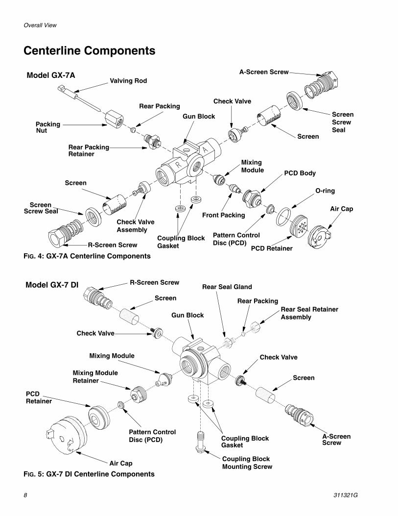
FIG. 4: GX-7A Centerline Components
FIG. 5: GX-7 DI Centerline Components
Model GX-7AValving Rod
PackingNut
Rear Packing
Gun Block
Rear PackingRetainer
A-Screen Screw
ScreenScrewSeal
Screen
Check Valve
MixingModule PCD Body
Front Packing
PCD Retainer
Air Cap
O-ring
Pattern ControlDisc (PCD)
Coupling BlockGasketR-Screen Screw
Check ValveAssembly
Screen
ScreenScrew Seal
Model GX-7 DI
Rear Seal RetainerAssembly
Rear Packing
Gun Block
Rear Seal Gland
Screen
R-Screen Screw
Check Valve
Mixing Module
Mixing ModuleRetainer
Pattern ControlDisc (PCD)
Air Cap
PCDRetainer
Check Valve
Screen
A-ScreenScrew
Coupling Block
Coupling BlockMounting Screw
Gasket
Overall View
311321G 9
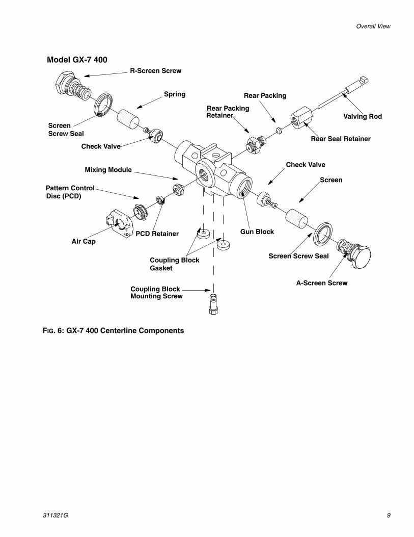
FIG. 6: GX-7 400 Centerline Components
Valving Rod
Rear Seal Retainer
Rear PackingRetainer
Rear Packing
A-Screen Screw
Screen Screw Seal
Screen
Check Valve
Coupling BlockMounting Screw
Coupling BlockGasket
Gun BlockPCD RetainerAir Cap
Pattern ControlDisc (PCD)
Mixing Module
Check Valve
Spring
ScreenScrew Seal
R-Screen Screw
Model GX-7 400
Overall View
10 311321G
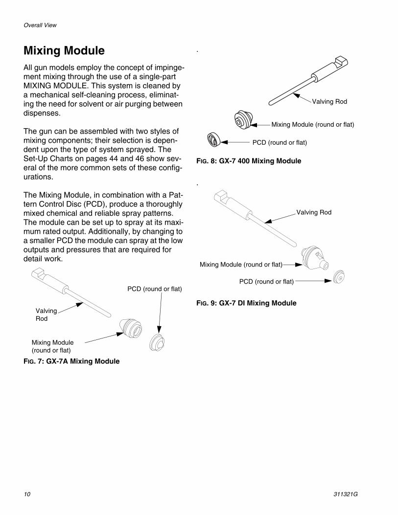
Mixing ModuleAll gun models employ the concept of impinge-ment mixing through the use of a single-part MIXING MODULE. This system is cleaned by a mechanical self-cleaning process, eliminat-ing the need for solvent or air purging between dispenses.
The gun can be assembled with two styles of mixing components; their selection is depen-dent upon the type of system sprayed. The Set-Up Charts on pages 44 and 46 show sev-eral of the more common sets of these config-urations.
The Mixing Module, in combination with a Pat-tern Control Disc (PCD), produce a thoroughly mixed chemical and reliable spray patterns. The module can be set up to spray at its maxi-mum rated output. Additionally, by changing to a smaller PCD the module can spray at the low outputs and pressures that are required for detail work.
FIG. 7: GX-7A Mixing Module
.
FIG. 8: GX-7 400 Mixing Module
.
FIG. 9: GX-7 DI Mixing ModuleValvingRod
Mixing Module (round or flat)
PCD (round or flat)
Valving Rod
Mixing Module (round or flat)
PCD (round or flat)
Valving Rod
Mixing Module (round or flat)
PCD (round or flat)
Operation Basics
311321G 11
Operation Basics
Isocyanate Hazard
Keep A and B Components Separate
Grounding
Check your local electrical code and propor-tioner manual for detailed grounding instruc-tions.
Ground the spray gun through connection to a Graco-approved grounded fluid supply hose.
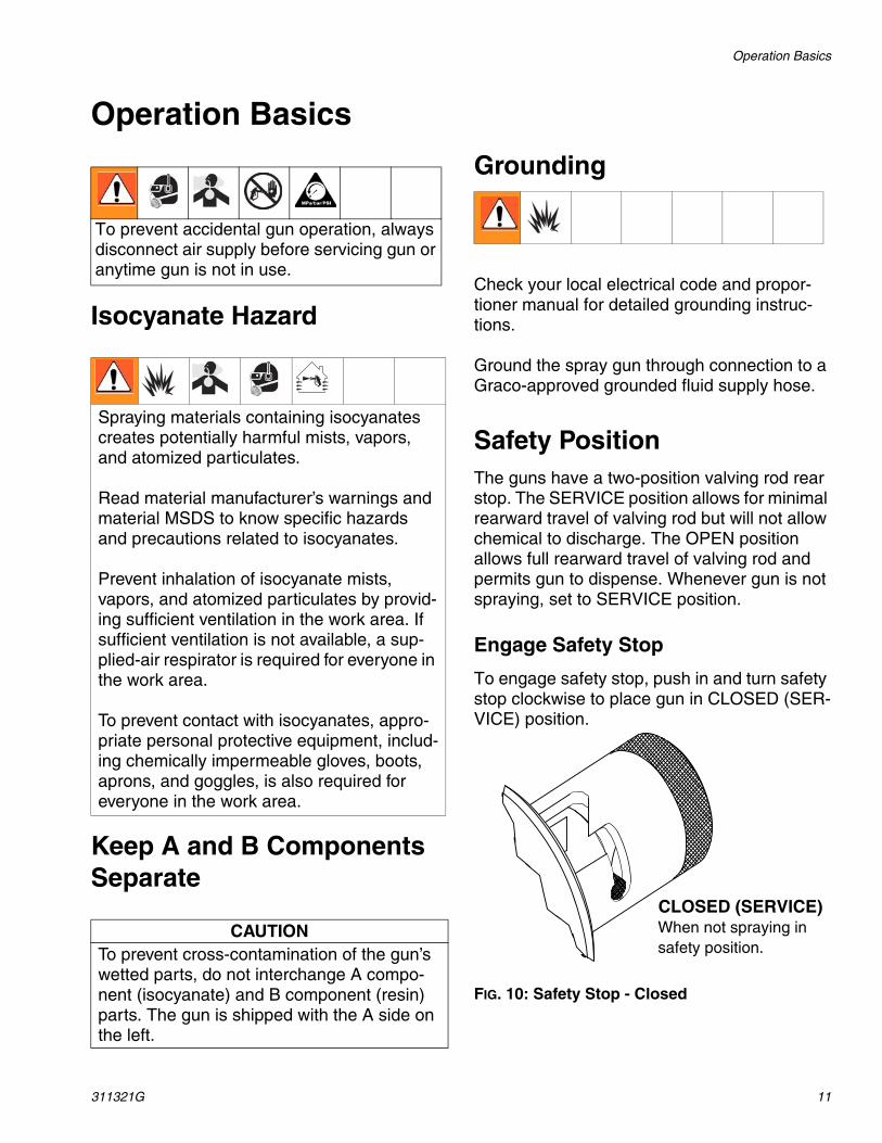
Safety PositionThe guns have a two-position valving rod rear stop. The SERVICE position allows for minimal rearward travel of valving rod but will not allow chemical to discharge. The OPEN position allows full rearward travel of valving rod and permits gun to dispense. Whenever gun is not spraying, set to SERVICE position.
Engage Safety Stop
To engage safety stop, push in and turn safety stop clockwise to place gun in CLOSED (SER-VICE) position.
FIG. 10: Safety Stop - Closed
To prevent accidental gun operation, always disconnect air supply before servicing gun or anytime gun is not in use.
Spraying materials containing isocyanates creates potentially harmful mists, vapors, and atomized particulates.
Read material manufacturer’s warnings and material MSDS to know specific hazards and precautions related to isocyanates.
Prevent inhalation of isocyanate mists, vapors, and atomized particulates by provid-ing sufficient ventilation in the work area. If sufficient ventilation is not available, a sup-plied-air respirator is required for everyone in the work area.
To prevent contact with isocyanates, appro-priate personal protective equipment, includ-ing chemically impermeable gloves, boots, aprons, and goggles, is also required for everyone in the work area.
CAUTIONTo prevent cross-contamination of the gun’s wetted parts, do not interchange A compo-nent (isocyanate) and B component (resin) parts. The gun is shipped with the A side on the left.
CLOSED (SERVICE) When not spraying in safety position.
Operation Basics
12 311321G
Disengage Safety Stop
To disengage safety stop, push in and turn safety stop counterclockwise to place gun in OPEN position (red band is exposed).
FIG. 11: Safety Stop - Open
Close Manual Valves
Closing manual valves prevents chemicals in heated hoses from entering gun. For your own safety, close manuals valves before servicing gun.
FIG. 12: Close Manual Valves
Air Hose Connection
Connect Air Hoses
Pull back sleeve of female fitting, insert male fitting and slide sleeve forward to secure con-nection.
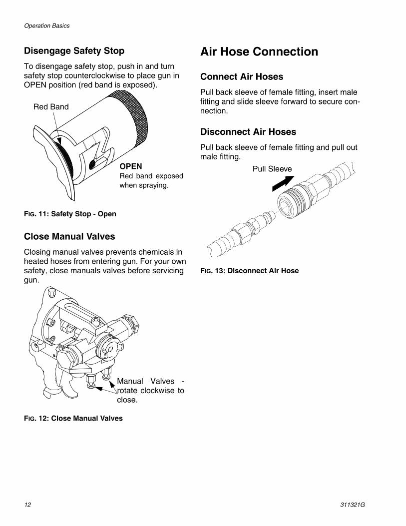
Disconnect Air Hoses
Pull back sleeve of female fitting and pull out male fitting.
FIG. 13: Disconnect Air Hose
OPENRed band exposedwhen spraying.
Red Band
Manual Valves -rotate clockwise toclose.
Pull Sleeve
Operation Basics
311321G 13
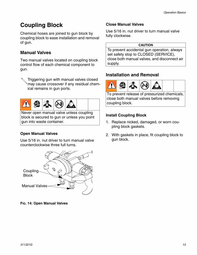
Coupling BlockChemical hoses are joined to gun block by coupling block to ease installation and removal of gun.
Manual Valves
Two manual valves located on coupling block control flow of each chemical component to gun.
Open Manual Valves
Use 5/16 in. nut driver to turn manual valve counterclockwise three full turns.
FIG. 14: Open Manual Valves
Close Manual Valves
Use 5/16 in. nut driver to turn manual valve fully clockwise.
Installation and Removal
Install Coupling Block
1. Replace nicked, damaged, or worn cou-pling block gaskets.
2. With gaskets in place, fit coupling block to gun block.
Triggering gun with manual valves closed may cause crossover if any residual chem-ical remains in gun ports.
Never open manual valve unless coupling block is secured to gun or unless you point gun into waste container.
CouplingBlock
Manual Valves
CAUTION
To prevent accidental gun operation, always set safety stop to CLOSED (SERVICE), close both manual valves, and disconnect air supply.
To prevent release of pressurized chemicals, close both manual valves before removing coupling block.
Operation Basics
14 311321G
3. Insert coupling block mounting screw and use 5/16 in. nut driver to tighten to gun block.
FIG. 15: Install Coupling Block
Remove Coupling Block
1. Set safety stop to CLOSED (SERVICE).
2. Disconnect air hose.
3. Close both manual valves.
4. Remove coupling block mounting screw.
5. Separate coupling block from gun.
6. Wipe mating surfaces of gun block and coupling block to remove residual chemical.
7. Cover exposed openings with grease.
Optional ConfigurationRefer to page 42. If bottom-mount hose con-nection is desired, alternate swivel fitting (2 and 3) with pipe plugs (1). Use pipe thread sealant. Do not cross-over which side each fit-ting is on.
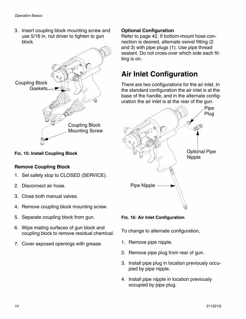
Air Inlet ConfigurationThere are two configurations for the air inlet. In the standard configuration the air inlet is at the base of the handle, and in the alternate config-uration the air inlet is at the rear of the gun.
FIG. 16: Air Inlet Configuration
To change to alternate configuration,
1. Remove pipe nipple.
2. Remove pipe plug from rear of gun.
3. Install pipe plug in location previously occu-pied by pipe nipple.
4. Install pipe nipple in location previously occupied by pipe plug.
Coupling BlockGaskets
Coupling Block Mounting Screw
PipePlug
Optional Pipe Nipple
Pipe Nipple

Operation Basics
311321G 15
Mixing Module and PCD Installation1. Install mixing module:
a. Disconnect gun from coupling block.
b. Connect air supply to gun.
c. Set safety stop to OPEN.
d. Hold down trigger and place module over tip of valving rod.
e. Align keying pin with hole in gun block and push in firmly (GX-7 DI model only).
f. Install front packing into module retainer (GX-7 model only).
g. Install module retainer, hand tight. Release trigger.
h. Use wrench to strongly tighten module retainer (250 in.-lbs.). GX-7 DI model only: use wrench to tighten module retainer (150 in.-lbs.). DO NOT OVERTIGHTEN.
2. Install PCD:
a. Disconnect air supply from gun.
b. Loosen forward stop screw (GX-7 model only).
c. Turn forward stop nut clockwise (as viewed from front of gun) 1-2 turns (GX-7 model only).
d. Slightly loosen rear seal retainer assembly.
e. Remove safety stop.
f. Use wrench to loosen piston locknut. Turn valving rod rearward as far as it will turn.
g. Place and orient PCD over mixing mod-ule retainer.
h. Install PCD retainer and hand tighten (GX-7 DI model only).
i. Install PCD retainer and wrench tighten (GX-7 model only).
3. Adjust valving rod. See procedure for appropriate gun model.
4. Set safety stop to OPEN position.
5. Check adjustment of valving rod:
a. With air supply connected, hold down gun trigger and loosen PCD retainer. Release trigger.
b. Hand tighten PCD retainer.
c. While maintaining tightening torque, trigger gun. Retainer should rotate approximately 1/10 of turn.
d. Release trigger.
Operation Basics
16 311321G
Valving Rod AdjustmentGX-7A and GX-7 400 Models Only
1. Push in rear stop to SERVICE position.
2. If attached, turn both manual valves fully clockwise to close (see Manual Valves, page 13).
3. Connect air line from gun to air source to pressurize air cylinder forward to CLOSED position.
4. Loosen forward stop locknut.
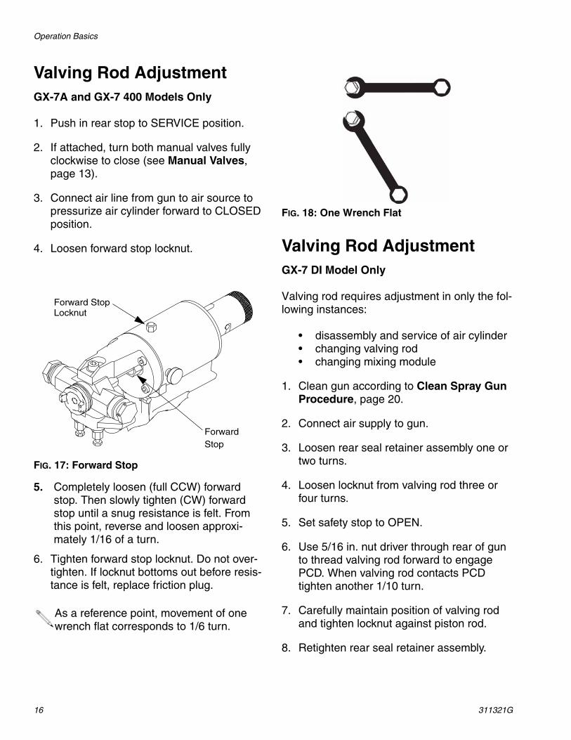
FIG. 17: Forward Stop
5. Completely loosen (full CCW) forward stop. Then slowly tighten (CW) forward stop until a snug resistance is felt. From this point, reverse and loosen approxi-mately 1/16 of a turn.
6. Tighten forward stop locknut. Do not over-tighten. If locknut bottoms out before resis-tance is felt, replace friction plug.
FIG. 18: One Wrench Flat
Valving Rod AdjustmentGX-7 DI Model Only
Valving rod requires adjustment in only the fol-lowing instances:
• disassembly and service of air cylinder• changing valving rod• changing mixing module
1. Clean gun according to Clean Spray Gun Procedure, page 20.
2. Connect air supply to gun.
3. Loosen rear seal retainer assembly one or two turns.
4. Loosen locknut from valving rod three or four turns.
5. Set safety stop to OPEN.
6. Use 5/16 in. nut driver through rear of gun to thread valving rod forward to engage PCD. When valving rod contacts PCD tighten another 1/10 turn.
7. Carefully maintain position of valving rod and tighten locknut against piston rod.
8. Retighten rear seal retainer assembly.
As a reference point, movement of one wrench flat corresponds to 1/6 turn.
ForwardStop
Forward StopLocknut
Operation Basics
311321G 17
Initial Set Up
1. Install female quick disconnect fitting to air supply hose bundled with chemical supply hoses.
2. Connect coupling block to hose bundle. Connect A-Isocyanate hose (red-tape) to notched fitting on coupling block. Connect R-Resin hose (blue-tape) to fitting without notches on coupling block.
3. Close both manual valves.
4. Pressurize A and R chemical hoses. Check for leaks. See Proportioner manual.
5. Bleed air from chemical hoses.
a. Use separate waste containers for A-ISO and R-Resin.
b. Hold coupling block with exit ports pointed into waste container.
c. Open one manual valve at a time to dis-pense into waste container.
d. Bleed each side until chemical leaving hoses is free of air.
e. Close both manual valves.
6. Use cloth soaked in gun cleaner to clean coupling block and mating surfaces.
7. Set safety stop to CLOSED (SERVICE).
8. Install coupling block to gun.
9. Proceed with daily start-up and shutdown procedures.
Operation Basics
18 311321G
Daily Start-up
1. Connect air supply to gun.
2. Adjust air cap adjustment valve. Turn knob counterclockwise to open valve and clock-wise to close valve
3. Adjust rear seal retainer.
4. Open both manual valves. See Coupling Block section, page 13.
5. Set safety stop to OPEN.
6. Test spray on disposable surface.
Daily Shutdown
1. Set safety stop to OPEN.
2. Close both manual valves.
3. Disconnect air supply from gun.
4. Shutdown proportioning unit as required. See Proportioner manual.
5. Clean as required. See Clean Spray Gun Procedure, page 20.
Ensure gun is attached to coupling block and air hose. Ensure proportioning unit is at desired temperature and pressure. Properly ground equipment to avoid static sparking that may result in fire or explosion.
Follow daily shutdown procedure when gun is out of service for any length of time, or for mid- or end-of-day service. See Clean Spray Gun Procedure, page 20.
Do not disassemble gun daily for cleaning if it is operating properly. However, if gun is removed from coupling block, it must be flushed and cleaned thoroughly.
Pressure Relief Procedure
311321G 19
Pressure Relief Procedure
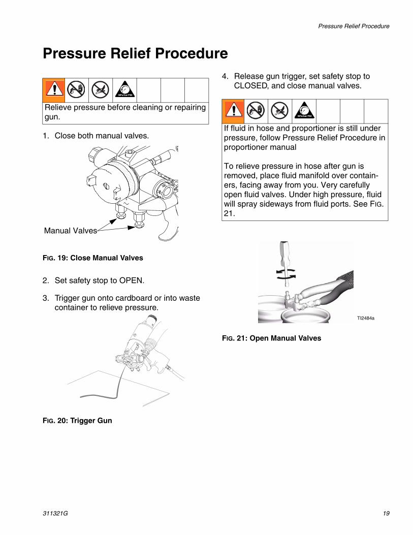
1. Close both manual valves.
FIG. 19: Close Manual Valves
2. Set safety stop to OPEN.
3. Trigger gun onto cardboard or into waste container to relieve pressure.
FIG. 20: Trigger Gun
4. Release gun trigger, set safety stop to CLOSED, and close manual valves.
FIG. 21: Open Manual Valves
Relieve pressure before cleaning or repairing gun.
Manual Valves
If fluid in hose and proportioner is still under pressure, follow Pressure Relief Procedure in proportioner manual
To relieve pressure in hose after gun is removed, place fluid manifold over contain-ers, facing away from you. Very carefully open fluid valves. Under high pressure, fluid will spray sideways from fluid ports. See FIG. 21.
TI2484a
Maintenance
20 311321G
Maintenance
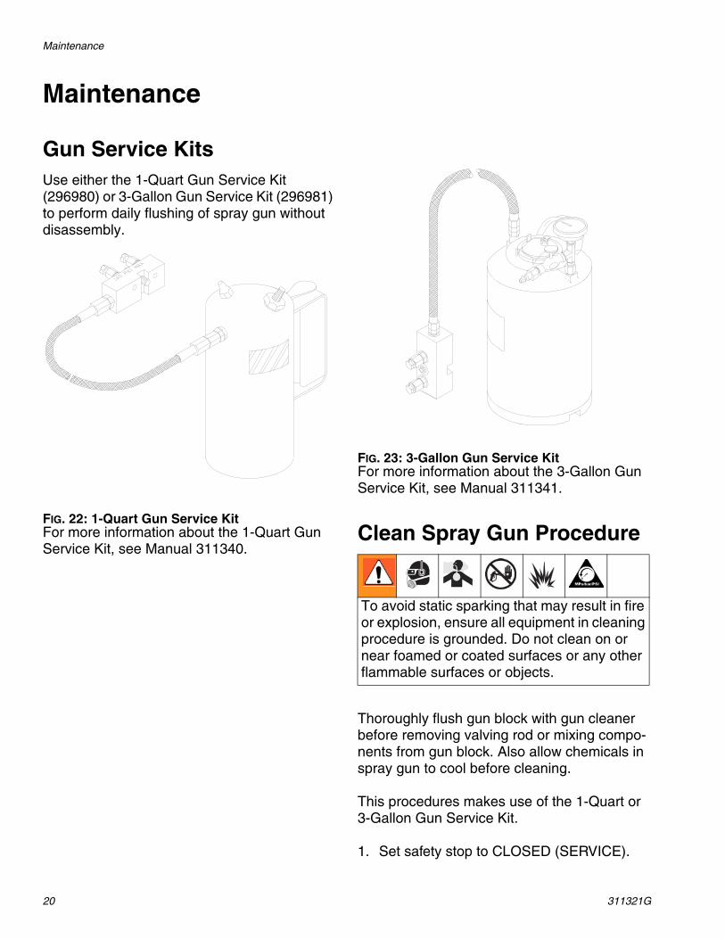
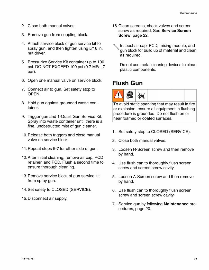
Gun Service KitsUse either the 1-Quart Gun Service Kit (296980) or 3-Gallon Gun Service Kit (296981) to perform daily flushing of spray gun without disassembly.
FIG. 22: 1-Quart Gun Service KitFor more information about the 1-Quart Gun Service Kit, see Manual 311340.
FIG. 23: 3-Gallon Gun Service KitFor more information about the 3-Gallon Gun Service Kit, see Manual 311341.
Clean Spray Gun Procedure
Thoroughly flush gun block with gun cleaner before removing valving rod or mixing compo-nents from gun block. Also allow chemicals in spray gun to cool before cleaning.
This procedures makes use of the 1-Quart or 3-Gallon Gun Service Kit.
1. Set safety stop to CLOSED (SERVICE).
To avoid static sparking that may result in fire or explosion, ensure all equipment in cleaning procedure is grounded. Do not clean on or near foamed or coated surfaces or any other flammable surfaces or objects.
Maintenance
311321G 21
2. Close both manual valves.
3. Remove gun from coupling block.
4. Attach service block of gun service kit to spray gun, and then tighten using 5/16 in. nut driver.
5. Pressurize Service Kit container up to 100 psi. DO NOT EXCEED 100 psi (0.7 MPa, 7 bar).
6. Open one manual valve on service block.
7. Connect air to gun. Set safety stop to OPEN.
8. Hold gun against grounded waste con-tainer.
9. Trigger gun and 1-Quart Gun Service Kit. Spray into waste container until there is a fine, unobstructed mist of gun cleaner.
10.Release both triggers and close manual valve on service block.
11.Repeat steps 5-7 for other side of gun.
12.After initial cleaning, remove air cap, PCD retainer, and PCD. Flush a second time to ensure thorough cleaning.
13.Remove service block of gun service kit from spray gun.
14.Set safety to CLOSED (SERVICE).
15.Disconnect air supply.
16.Clean screens, check valves and screen screw as required. See Service Screen Screw, page 22.
Flush Gun
1. Set safety stop to CLOSED (SERVICE).
2. Close both manual valves.
3. Loosen R-Screen screw and then remove by hand.
4. Use flush can to thoroughly flush screen screw and screen screw cavity.
5. Loosen A-Screen screw and then remove by hand.
6. Use flush can to thoroughly flush screen screw and screen screw cavity.
7. Service gun by following Maintenance pro-cedures, page 20.
Inspect air cap, PCD, mixing module, and gun block for build up of material and clean as required.
Do not use metal cleaning devices to clean plastic components.
To avoid static sparking that may result in fire or explosion, ensure all equipment in flushing procedure is grounded. Do not flush on or near foamed or coated surfaces.
Repair
22 311321G
Repair
Service Screen Screw
1. Flush gun according to Clean Spray Gun Procedure, page 20.
2. Unthread screen screw from gun block.
3. Remove check valve from screen screw. Clean valve with gun cleaner and inspect for damage. Replace if necessary.
4. Remove screen from screen screw. Soak in gun cleaner or replace if clogged or dirty.
5. Clean screen screw cavity. If any particles are visible, clean with clean out drills and flush with gun cleaner.
6. Inspect screen screw seal for damage. Replace if necessary.
7. Reinstall screen screw in gun block. Make sure it is tight.
8. Flush gun with mixing module removed.
Remove Centerline ComponentsRefer to FIG. 4 through FIG. 6 for diagrams of centerline components for all gun models.
1. Flush gun according to Clean Spray Gun Procedure, page 20.
2. Connect air supply to gun. Set safety stop to OPEN.
3. Remove air cap.
4. Trigger gun and hold it to relieve pressure on PCD retainer.
5. Remove PCD retainer by turning it counter-clockwise.
6. Remove PCD from mixing module retainer.
7. Remove mixing module retainer.
8. Set safety stop to OPEN. Depress and release gun trigger to unseat it. Remove mixing module off end of valving rod. Set safety stop to CLOSED (SERVICE).
9. Loosen rear packing nut 1-2 turns.
10.Push safety stop partially forward, rotate it counterclockwise, and slide off air cylinder.
Shutdown proportioner and allow chemicals to cool before servicing gun.
Clean A and R components in separate con-tainers to avoid cross contamination.
CAUTION
Any material left in cavity on downstream side of screen will clog mixing module.
To remove PCD that is stuck, set safety stop to OPEN, depress and release gun trigger to unseat it. Set safety stop to CLOSED (SERVICE).
CAUTION
Do not use sharp objects or metal tools to remove mixing module.
Repair
311321G 23
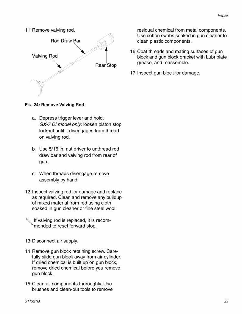
11.Remove valving rod.
FIG. 24: Remove Valving Rod
a. Depress trigger lever and hold.GX-7 DI model only: loosen piston stop locknut until it disengages from thread on valving rod.
b. Use 5/16 in. nut driver to unthread rod draw bar and valving rod from rear of gun.
c. When threads disengage remove assembly by hand.
12. Inspect valving rod for damage and replace as required. Clean and remove any buildup of mixed material from rod using cloth soaked in gun cleaner or fine steel wool.
13.Disconnect air supply.
14.Remove gun block retaining screw. Care-fully slide gun block away from air cylinder. If dried chemical is built up on gun block, remove dried chemical before you remove gun block.
15.Clean all components thoroughly. Use brushes and clean-out tools to remove
residual chemical from metal components. Use cotton swabs soaked in gun cleaner to clean plastic components.
16.Coat threads and mating surfaces of gun block and gun block bracket with Lubriplate grease, and reassemble.
17. Inspect gun block for damage.
If valving rod is replaced, it is recom-mended to reset forward stop.
Rear Stop
Rod Draw Bar
Valving Rod
Repair
24 311321G
Install Centerline ComponentsGX-7 DI Model Only
Before installation, ensure all gun components are clean and dry. Lubricate all moving parts and threads.
1. Install rear packing gland with packing wrench. Tighten onto gun block.
2. Install rear packing retainer loosely.
3. Install valving rod.
a. Connect valving rod to rod draw bar and insert into air cylinder.
b. Use 5/16 in. nut driver to thread assem-bly tight into end cap.GX-7 DI model only: thread rod until approximately 3/16 in. to 1/4 in.of thread protrudes from end of piston rod.
4. Thread locknut onto valving rod by hand.
5. Carefully slide gun block onto valving rod toward air cylinder. Install gun block onto gun block mounting bracket.
6. Install safety stop; leave in OPEN position.
7. Connect air supply to gun.
8. Depress gun trigger and slide mixing mod-ule over end of valving rod. GX-7 DI model only: ensure valving rod alignment pin enters alignment slot in gun block. Keep gun trigger depressed.
9. With gun trigger depressed, thread mixing module retainer or PCD body with packing installed, by hand, and then wrench tighten.
10.Release gun trigger.
11. Install PCD over end of mixing module retainer.
12.Thread PCD retainer onto gun block. Hand tight.
13.Rotate flat PCD to adjust orientation as required.
14.Adjust valving rod. See Valving Rod Adjustment, page 16.
15.Thread air cap into place; hand tight.
16.Slide safety stop onto rear of air cylinder. Push safety stop partially forward and rotate clockwise to set to OPEN.
17.Set safety stop to CLOSED (SERVICE).
CAUTION
To avoid damage to module and gun block, do not overtighten mixing module retainer.

Repair
311321G 25
Replace End Cap and Air Piston Assembly
FIG. 25: GX-7 DI End Cap and Air Piston Assembly
1. Clean gun according to Clean Spray Gun Procedure, page 20.
2. Loosen rear packing nut 1-2 turns.
3. Push safety stop partially forward, rotate counterclockwise, and slide safety stop off air cylinder.
4. Remove valving rod. See Remove Center-line Components, page 22.
5. Disconnect air supply from gun.
6. Remove rear head cap screw and cylinder clamp from handle.
7. Remove end cap from air cylinder.
8. Inspect end cap o-ring. Replace if dam-aged. Install new end cap o-ring after lightly coating it with Lubriplate grease.
9. Inspect rear U-cup seal or o-ring for dam-age. Replace if necessary. If removed,
ensure “cup” faces front of air cylinder when replacing.
10.By hand, pull piston assembly out of air cyl-inder and inspect o-ring for damage. Replace if necessary. Apply Lubriplate grease prior to installation.
11. If air was escaping around piston rod dur-ing operation, replace front u-cup seal or o-ring. Apply Lubriplate grease and ensure “cup” faces rear of air cylinder.
12. Insert piston and rod assembly into air cyl-inder. Take care to not damage front cup seal as rod passes through.
13. Insert piston spring. (For GX-7 DI models, also insert piston spacer.)
14.Reinstall end cap into air cylinder.
15.Retighten rear socket head cap screw and cylinder clamp to handle.
16.Reinstall valving rod. Connect valving rod to draw bar. Lubricate and thread into end cap.
17.Adjust valving rod; see Valving Rod Adjustment, page 16.
18.Slide safety stop onto rear of air cylinder. Push safety stop partially forward and rotate clockwise to set to OPEN.
19.Set safety stop to CLOSED (SERVICE).
20.Tighten rear packing nut.
GX-7 DI Shown
End Cap
Spacer
RearU-CupSealPiston
Spring
Piston Assembly
Front U-Cup Seal
Socket Head Cap Screw
Cylinder Clamp

Repair
26 311321G
Replace Trigger Valve O-Rings1. Clean gun according to Clean Spray Gun
Procedure, page 20.
2. Disconnect air supply from gun.
FIG. 26: Replace Trigger Valve O-Ring
3. Remove mounting screw and locknut that hold trigger in place. Remove trigger.
4. Remove valve retainer nut.
5. Pull out valve spool and valve spring. Remove old o-rings.
6. Prior to installation, liberally lubricate all o-rings with lubricant provided in Rebuild kit.
7. Remove pipe plug from rear of gun handle.
8. Remove rear internal pipe plug (under pipe plug).
9. Use pin punch and hammer to gently tap spring seat until it and valve liner push out opposite end of hole.
10.Remove 4 o-rings on liner.
11.Apply thick coat of Lubriplate grease to new o-rings and install.
12.Clean valve hole. Remove any dirt and debris. Apply thick coat of Lubriplate grease to inside of valve hole.
13.Slide spring seat into gun handle air valve hole, tapered end first, until it bottoms out.
14.Push valve liner in as far as it will go. Tem-porarily screw in valve retainer nut, which aligns valve liner and valve spool. Remove valve retainer nut.
15.With valve spool spring in place, insert valve spool into valve liner. Screw in valve retainer nut. Do not overtighten.
16.Apply small amount of pipe thread sealant to 1/16 in. pipe plug threads. Screw pipe plug in place.
17.Apply small amount of pipe thread sealant to 1/8 in. pipe plug (or 1/8 in. pipe nipple) and install.
18.Reinstall trigger using screw and locknut.
Follow steps 7-15 to replace o-rings on valve liner. If o-rings do not need to be replaced, go to step 16.
For guns configured with air inlet at rear of gun handle, pipe nipple replaces pipe plug. Remove pipe nipple.
Refer to Parts, page 30.
Repair
311321G 27
Clean Mixing Module1. Flush gun according to Clean Spray Gun
Procedure, page 20.
2. Connect air supply to gun. Set safety stop to OPEN.
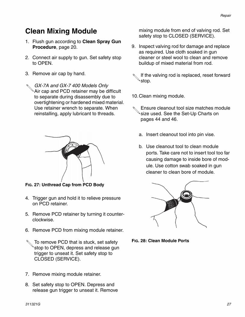
3. Remove air cap by hand.
FIG. 27: Unthread Cap from PCD Body
4. Trigger gun and hold it to relieve pressure on PCD retainer.
5. Remove PCD retainer by turning it counter-clockwise.
6. Remove PCD from mixing module retainer.
7. Remove mixing module retainer.
8. Set safety stop to OPEN. Depress and release gun trigger to unseat it. Remove
mixing module from end of valving rod. Set safety stop to CLOSED (SERVICE).
9. Inspect valving rod for damage and replace as required. Use cloth soaked in gun cleaner or steel wool to clean and remove buildup of mixed material from rod.
10.Clean mixing module.
a. Insert cleanout tool into pin vise.
b. Use cleanout tool to clean module ports. Take care not to insert tool too far causing damage to inside bore of mod-ule. Use cotton swab soaked in gun cleaner to clean bore of module.
FIG. 28: Clean Module Ports
GX-7A and GX-7 400 Models OnlyAir cap and PCD retainer may be difficult to separate during disassembly due to overtightening or hardened mixed material. Use retainer wrench to separate. When reinstalling, apply lubricant to threads.
To remove PCD that is stuck, set safety stop to OPEN, depress and release gun trigger to unseat it. Set safety stop to CLOSED (SERVICE).
If the valving rod is replaced, reset forward stop.
Ensure cleanout tool size matches module size used. See the Set-Up Charts on pages 44 and 46.
Repair
28 311321G
Install Mixing Module1. Install safety stop; leave in OPEN position.
2. Connect air supply to gun.
3. Depress gun trigger and slide mixing mod-ule over end of valving rod. GX-7 DI model only: ensure valving rod alignment pin enters alignment slot in gun block. Keep gun trigger depressed.
4. With gun trigger depressed, thread mixing module retainer or PCD body with packing installed, by hand, and then wrench tighten.
5. Release gun trigger.
6. Install PCD over end of mixing module retainer.
7. Thread PCD retainer onto gun block. Hand tight.
8. Rotate flat PCD to adjust orientation as required.
9. Adjust valving rod. See Valving Rod Adjustment, page 16.
10.Thread air cap into place; hand tight.
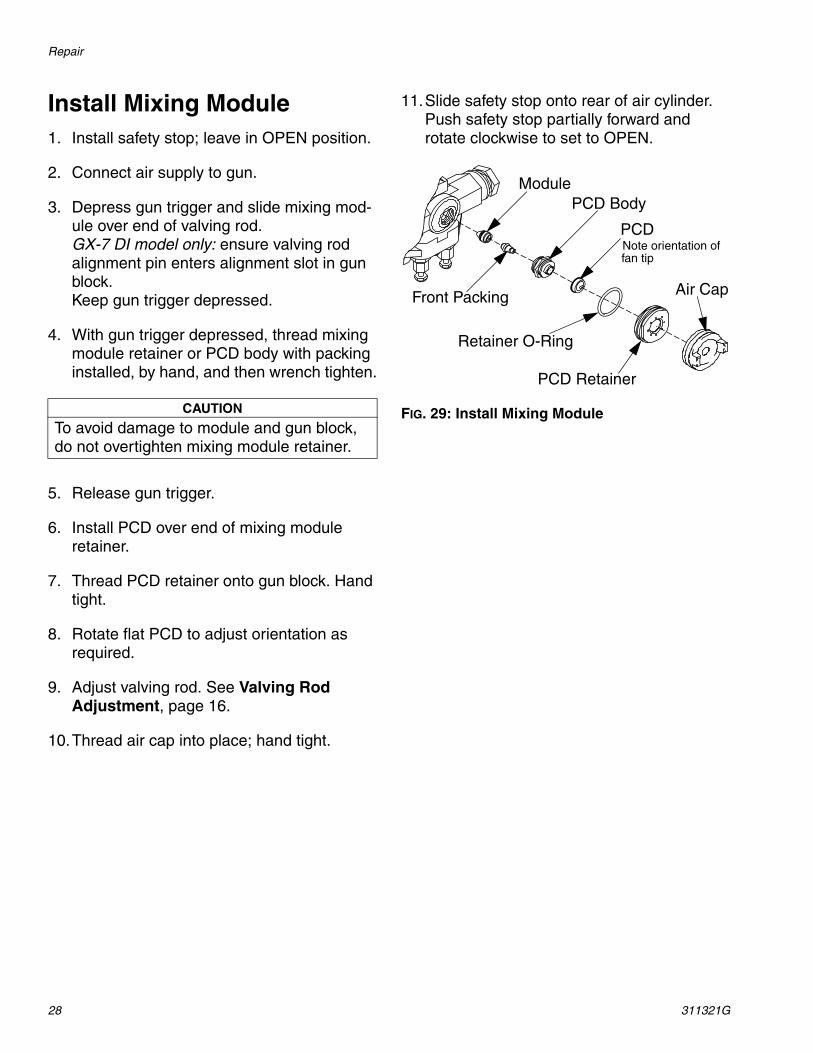
11.Slide safety stop onto rear of air cylinder. Push safety stop partially forward and rotate clockwise to set to OPEN.
FIG. 29: Install Mixing ModuleCAUTION
To avoid damage to module and gun block, do not overtighten mixing module retainer.
Module
Front Packing
PCD Body
Retainer O-Ring
PCD Retainer
PCD
Air Cap
Note orientation offan tip
Repair
311321G 29
Clean Pattern Control Disc1. Set safety stop to CLOSED (SERVICE).
2. Close both manual valves.
3. Turn off air to air cap.
4. Use cotton swab soaked in gun cleaner to clean external surface of material build up. Light scrubbing with impinger cleanout brush may also be required.
a. Trigger gun to SERVICE position and clean orifice area.
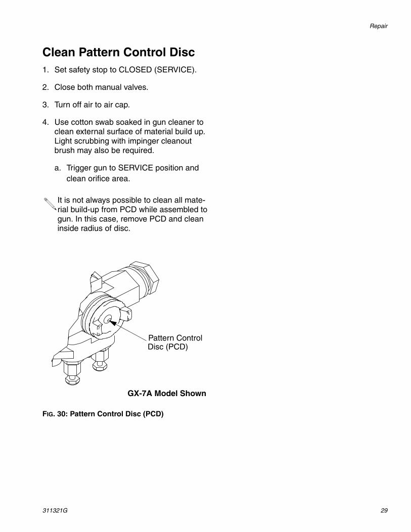
FIG. 30: Pattern Control Disc (PCD)
It is not always possible to clean all mate-rial build-up from PCD while assembled to gun. In this case, remove PCD and clean inside radius of disc.
GX-7A Model Shown
Pattern ControlDisc (PCD)

Parts
30 311321G
Parts
GX-7A Model Final AssemblyPart Numbers 295542, 295543, 295544, 29545
2
3
4
6
5
7
8
9
10
1112
13
14
15
16
17
18
19
217
89
22
25
2324
1
20
Parts
311321G 31
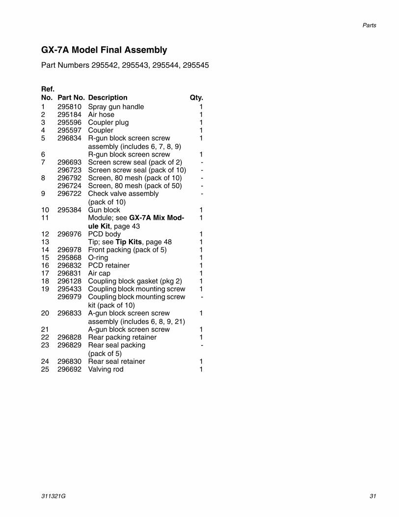
GX-7A Model Final Assembly
Part Numbers 295542, 295543, 295544, 295545
Ref. No. Part No. Description Qty.1 295810 Spray gun handle 12 295184 Air hose 13 295596 Coupler plug 14 295597 Coupler 15 296834 R-gun block screen screw
assembly (includes 6, 7, 8, 9)1
6 R-gun block screen screw 17 296693 Screen screw seal (pack of 2) -
296723 Screen screw seal (pack of 10) -8 296792 Screen, 80 mesh (pack of 10) -
296724 Screen, 80 mesh (pack of 50) -9 296722 Check valve assembly
(pack of 10)-
10 295384 Gun block 111 Module; see GX-7A Mix Mod-
ule Kit, page 431
12 296976 PCD body 113 Tip; see Tip Kits, page 48 114 296978 Front packing (pack of 5) 115 295868 O-ring 116 296832 PCD retainer 117 296831 Air cap 118 296128 Coupling block gasket (pkg 2) 119 295433 Coupling block mounting screw 1
296979 Coupling block mounting screw kit (pack of 10)
-
20 296833 A-gun block screen screw assembly (includes 6, 8, 9, 21)
1
21 A-gun block screen screw 122 296828 Rear packing retainer 123 296829 Rear seal packing
(pack of 5)-
24 296830 Rear seal retainer 125 296692 Valving rod 1
Parts
32 311321G
GX-7 DI Model Final Assembly (295541)
5
6
7
8
2
3
4
10
12
1314
15
16
6
7
1718
19
9
11
1
Parts
311321G 33
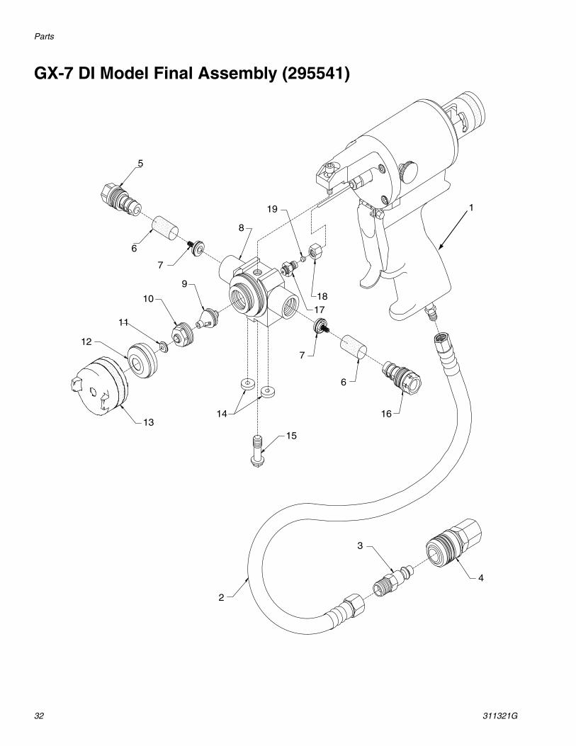
GX-7 DI Model Final Assembly (295541)
Ref. No. Part No. Description Qty.1 295809 Spray gun handle assembly 12 295184 Air hose, 1/4 in. x 23 in. (FXF) 13 295596 Coupler plug 14 295597 Coupler 15 295835 R-screen screw 16 296792 Screen, 80 mesh (pack of 10) -
296724 Screen, 80 mesh (pack of 50) -7 296713 Check valve assembly
(pack of 2)2
8 295860 Gun block 19 Module; see GX-7 DI Model
Specifications, page 471
10 295837 Module retainer 111 Tip; see Tip Kits, page 48 112 296865 Tip retainer 113 295838 Air cap 114 296128 Coupling block gasket
(pack of 2)-
15 295433 Coupling block mounting screw 1296979 Coupling block mounting screw
(pack of 2)-
16 295834 A-screen screw 117 295836 Rear seal gland 118 296864 Rear seal retainer assembly 119 296829 Rear seal packing (pack of 5) -20 295383 Coupling block (not shown) 1

Parts
34 311321G
GX-7 400 Model Final Assembly (295540)
7
11
12
9
614
15
16
8
18
21
19
20
2
13
4
3
1
10
12
96
5
22
23
Parts
311321G 35
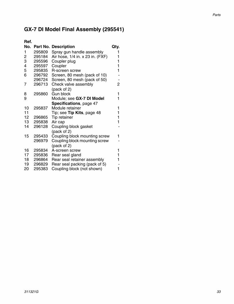
GX-7 400 Model Final Assembly (295540)
Ref. No. Part No. Description Qty.1 295184 Air hose 12 296128 Coupling block gasket
(pack of 2)-
3 295596 Coupler plug 14 295597 Coupler 15 295384 Gun block (includes 13) 16 296722 Check valve assembly
(pack of 10)-
7 295799 Spray gun handle assembly 18 296692 Valving rod 29 296792 Screen-80, mesh (pack of 10) -
296724 Screen-80, mesh (pack of 50) -10 A-Screen screw 111 R-Screen screw 112 296693 Screen screw seal (pack of 2) -
296723 Screen screw seal (pack of 10) -13 295433 Coupling block mounting screw 1
296979 Coupling block mounting screw kit (pack of 2)
-
14 296828 Rear packing retainer 115 296829 Rear seal packing
(pack of 5)1
16 296830 Rear seal retainer 118 Module; see GX-7 400 Mix
Module Kit, page 451
19 296836 Retainer 120 296837 Air cap 121 Tip; see Tip Kits, page 48 122 296833 A-gun block screen screw
assembly (includes 6, 9, 10, 12)
-
23 296834 R-gun block screen screw assembly(includes 6, 9, 10, 12)
-
Parts
36 311321G
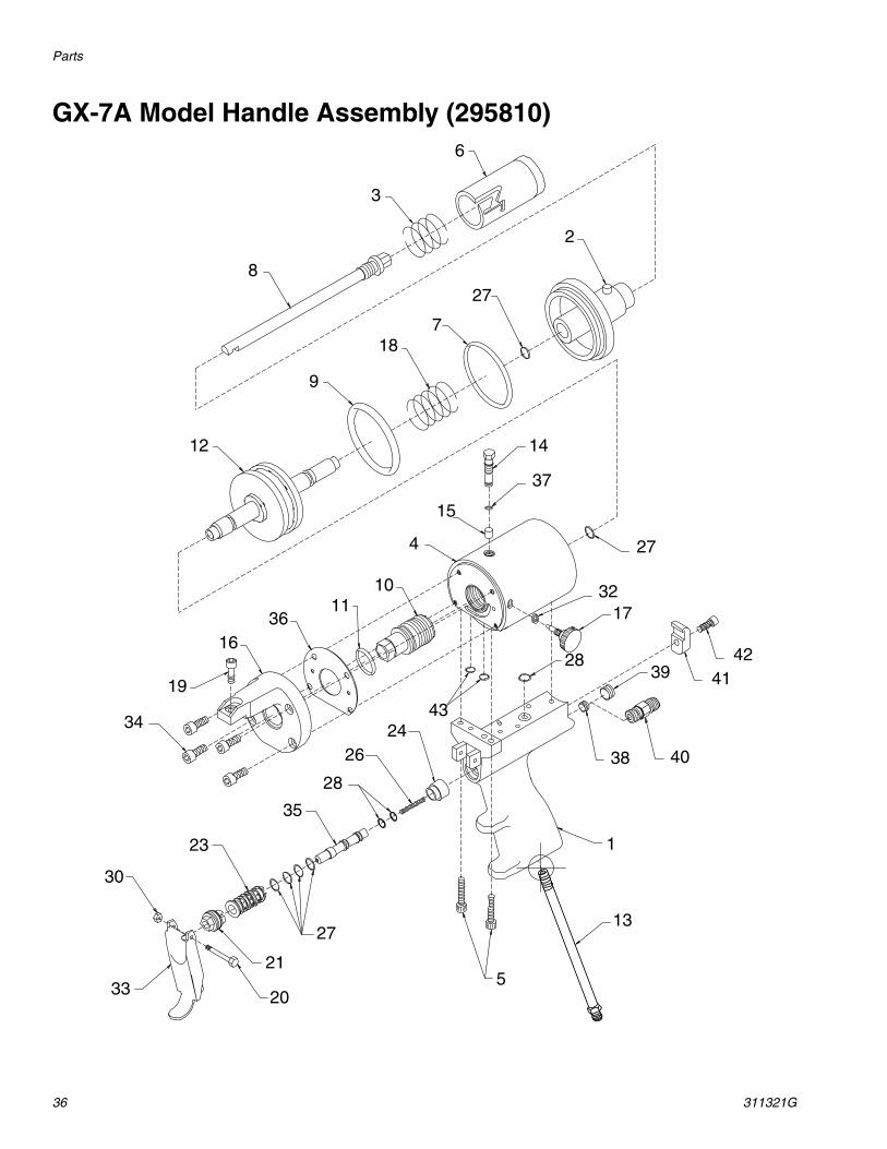
GX-7A Model Handle Assembly (295810)6
3
8
2
27
718
9
12 14
37
27
15
4
1011
3616
19
34
3217
28 424139
4038
1
13
5
4324
26
28
35
27
21
20
23
30
33
Parts
311321G 37
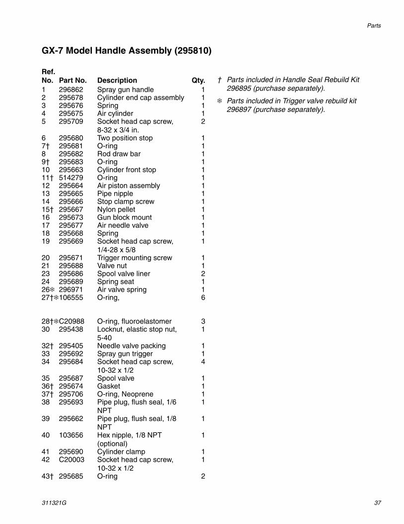
GX-7 Model Handle Assembly (295810)
† Parts included in Handle Seal Rebuild Kit 296895 (purchase separately).
❄ Parts included in Trigger valve rebuild kit 296897 (purchase separately).
Ref. No. Part No. Description Qty.1 296862 Spray gun handle 12 295678 Cylinder end cap assembly 13 295676 Spring 14 295675 Air cylinder 15 295709 Socket head cap screw,
8-32 x 3/4 in.2
6 295680 Two position stop 17† 295681 O-ring 18 295682 Rod draw bar 19† 295683 O-ring 110 295663 Cylinder front stop 111† 514279 O-ring 112 295664 Air piston assembly 113 295665 Pipe nipple 114 295666 Stop clamp screw 115† 295667 Nylon pellet 116 295673 Gun block mount 117 295677 Air needle valve 118 295668 Spring 119 295669 Socket head cap screw,
1/4-28 x 5/81
20 295671 Trigger mounting screw 121 295688 Valve nut 123 295686 Spool valve liner 224 295689 Spring seat 126❄ 296971 Air valve spring 127†❄106555 O-ring, 6
28†❄C20988 O-ring, fluoroelastomer 330 295438 Locknut, elastic stop nut,
5-401
32† 295405 Needle valve packing 133 295692 Spray gun trigger 134 295684 Socket head cap screw,
10-32 x 1/24
35 295687 Spool valve 136† 295674 Gasket 137† 295706 O-ring, Neoprene 138 295693 Pipe plug, flush seal, 1/6
NPT1
39 295662 Pipe plug, flush seal, 1/8 NPT
1
40 103656 Hex nipple, 1/8 NPT (optional)
1
41 295690 Cylinder clamp 142 C20003 Socket head cap screw,
10-32 x 1/21
43† 295685 O-ring 2

Parts
38 311321G
GX-7 DI Model Handle Assembly (295809)25
10
918
12
17
2
3411
19
13
20
14
34
3
40
1522
31
24
2916
30 37827
3936
33
1
21
26
738
305
28
4
32
6
2335
Parts
311321G 39
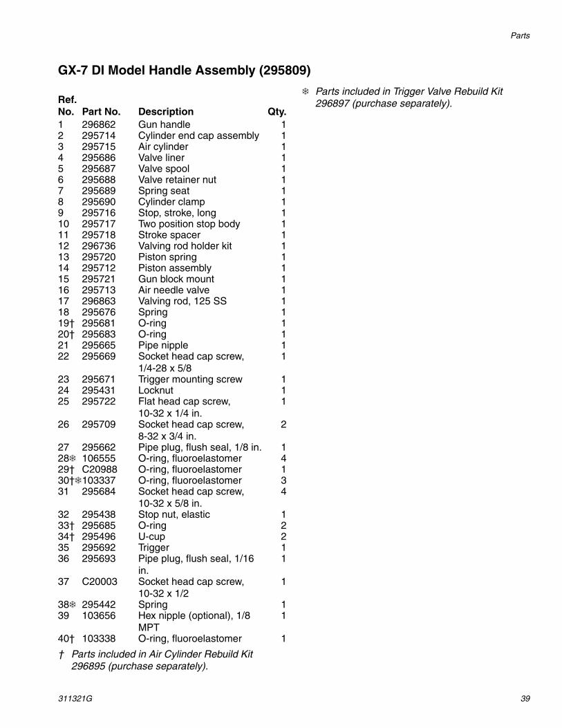
GX-7 DI Model Handle Assembly (295809)
† Parts included in Air Cylinder Rebuild Kit 296895 (purchase separately).
❄ Parts included in Trigger Valve Rebuild Kit 296897 (purchase separately).Ref.
No. Part No. Description Qty.1 296862 Gun handle 12 295714 Cylinder end cap assembly 13 295715 Air cylinder 14 295686 Valve liner 15 295687 Valve spool 16 295688 Valve retainer nut 17 295689 Spring seat 18 295690 Cylinder clamp 19 295716 Stop, stroke, long 110 295717 Two position stop body 111 295718 Stroke spacer 112 296736 Valving rod holder kit 113 295720 Piston spring 114 295712 Piston assembly 115 295721 Gun block mount 116 295713 Air needle valve 117 296863 Valving rod, 125 SS 118 295676 Spring 119† 295681 O-ring 120† 295683 O-ring 121 295665 Pipe nipple 122 295669 Socket head cap screw,
1/4-28 x 5/81
23 295671 Trigger mounting screw 124 295431 Locknut 125 295722 Flat head cap screw,
10-32 x 1/4 in.1
26 295709 Socket head cap screw,8-32 x 3/4 in.
2
27 295662 Pipe plug, flush seal, 1/8 in. 128❄ 106555 O-ring, fluoroelastomer 429† C20988 O-ring, fluoroelastomer 130†❄103337 O-ring, fluoroelastomer 331 295684 Socket head cap screw,
10-32 x 5/8 in.4
32 295438 Stop nut, elastic 133† 295685 O-ring 234† 295496 U-cup 235 295692 Trigger 136 295693 Pipe plug, flush seal, 1/16
in.1
37 C20003 Socket head cap screw,10-32 x 1/2
1
38❄ 295442 Spring 139 103656 Hex nipple (optional), 1/8
MPT1
40† 103338 O-ring, fluoroelastomer 1

Parts
40 311321G
GX-7 400 Model Handle Assembly (295799)15
14
17
32
3
1625
18
21 23
39
40
3
831
11332
10
24
30
1920
29
28
26
5
4
7
38
22
1
3712
4
35
3
34
6
36
279
13
Parts
311321G 41
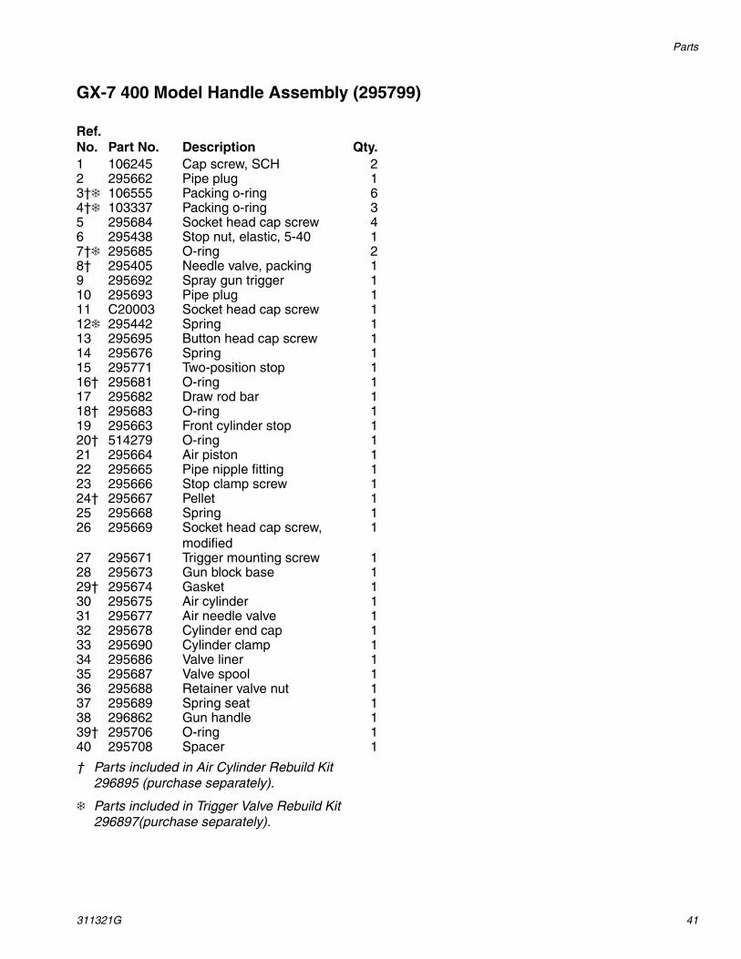
GX-7 400 Model Handle Assembly (295799)
† Parts included in Air Cylinder Rebuild Kit 296895 (purchase separately).
❄ Parts included in Trigger Valve Rebuild Kit 296897(purchase separately).
Ref. No. Part No. Description Qty.1 106245 Cap screw, SCH 22 295662 Pipe plug 13†❄ 106555 Packing o-ring 64†❄ 103337 Packing o-ring 35 295684 Socket head cap screw 46 295438 Stop nut, elastic, 5-40 17†❄ 295685 O-ring 28† 295405 Needle valve, packing 19 295692 Spray gun trigger 110 295693 Pipe plug 111 C20003 Socket head cap screw 112❄ 295442 Spring 113 295695 Button head cap screw 114 295676 Spring 115 295771 Two-position stop 116† 295681 O-ring 117 295682 Draw rod bar 118† 295683 O-ring 119 295663 Front cylinder stop 120† 514279 O-ring 121 295664 Air piston 122 295665 Pipe nipple fitting 123 295666 Stop clamp screw 124† 295667 Pellet 125 295668 Spring 126 295669 Socket head cap screw,
modified1
27 295671 Trigger mounting screw 128 295673 Gun block base 129† 295674 Gasket 130 295675 Air cylinder 131 295677 Air needle valve 132 295678 Cylinder end cap 133 295690 Cylinder clamp 134 295686 Valve liner 135 295687 Valve spool 136 295688 Retainer valve nut 137 295689 Spring seat 138 296862 Gun handle 139† 295706 O-ring 140 295708 Spacer 1

Parts
42 311321G
Coupling Block Assembly (295383) All models
1
5
1
6
34
2
Ref. No. Part No. Description
Qty.
1 295662 Pipe plug, flush seal, 1/8 in. 22 117634 R-swivel fitting 13 117635 A-swivel fitting 14 295693 Pipe plug, flush seal,
1/16 in.2
5 296970 Manual valve assembly 26 296215 Coupling block 1

Specifications
311321G 43
Specifications
GX-7A Mix Module Kit
† Module Kits include one mix module and both clea-nout tools. See following table.
❄ Some Module Kits also available in packs. See follow-ing table.
Module Kit†❄ Module Only Cleanout Tool
Part No. Size Ref. Part No. Size Ref.(A) Iso Port
Part No.Diameterin/(mm)
(R) Resin PortPart No.
Diameterin/(mm)
296909 #1 Round 296907 #1 Round 246807 .0320 (.81) 246807 .032 (.81)
296916 #2 Round 296225 #2 Round 246816 .018 (.45) 246816 .018 (.45)
296919 #3 Round 296226 #3 Round 276984 .0225 (.57) 246816 .018 (.45)
296921 #4 Round n/a #4 Round 296290 .035 (.89) 246807 .032 (.81)
296923 #5 Round 296228 #5 Round 276984 .0225 (.57) 248892 .028 (.71)
296925 #7 Flat 296230 #7 Flat 248892 .028 (.71) 248892 .028 (.71)
296906 #10 Flat 296233 #10 Flat 296291 .036 (.91) 296291 .036 (.91)
296910 #12 Flat 296130 #12 Flat 296286 .021 (.53) 296286 .021 (.53)
296915 #16 Round n/a #16 Round 248892 .028 (.71) 248892 .028 (.71)
296917 #22 Round n/a #22 Round 276984 .0225 (.57) 276984 .0225 (.57)
296875 A2 Pour n/a A2 Pour 246816 .018 (.45) 246816 .018 (.45)
296876 A3 Pour n/a A3 Pour 248640 .039 (.99) 248640 .039 (.99)
296868 A5 Pour n/a A5 Pour 246807 .032 (.81) 246807 .032 (.81)
296870 A5-FS Pour n/a A5-FS Pour 246807 .032 (.81) 246807 .032 (.81)
Each module has a specially sized cleanout tool. To avoid damage to module, use correct cleanout tool.
Mix Module Kit
Part No. Size Ref. Qty./Pack
296908 #1 Round 12 (with 2 drills)
296869 A5 Pour 12
296871 A5-FS Pour 12
296872 A10 Pour 12
296873 A20 Pour 12
296874 A2 Pour 12 (with 2 drills)
296911 STD Blank 5
296912 STD Blank 100
296913 PEEK Blank 5

Specifications
44 311321G
Set-Up Chart for GX-7A Model
❄ At 24 in. above substrate❖ At 18 in. above substrate
Pres-sure (psi)
Output (lbs/min)
Pattern Dia.
(inches)Module Part
No.
Polyol Port Size
No. Orifices
Iso Port Size
No. Orifices Tip
Round Spray Pattern
1000 22 ❄22 296909 (#1) .0320 4 .0320 4 296712
1000 12 ❄12 296919 (#3) .0180 4 .0225 4 296710
1600 16 ❄14 296923 (#5) .0280 4 .0225 4 296710
2000 30 ❄24 296909 (#1) .0320 4 .0320 4 296694
3000 40 ❄24 296921 (#4) .0320 4 .0350 4 296695
Pour Pattern
600 3.5 N/A 296875 (A2) .0180 1 .0180 1 296697
600 12 N/A 296876 (A3) .0390 1 .0390 1 296697
Fan Spray Pattern
1000 12 ❖ 16 x 4 296925 (#7) .0280 2 .0280 2 296704
1500 24 ❖ 22 x 4 296906 (#10)
.0360 2 .0360 2 296703
1500 5 ❖ 16 x 3 296910 (#12)
.0210 2 .0210 2 296705

Specifications
311321G 45
GX-7 400 Mix Module Kit
Module Kits Cleanout Drill
Part No. Size Ref. QuantityIso PortPart No.
Diameterin/(mm)
Polyol PortPart No.
Diameterin/(mm)
296885296884
402 Round 112
246816 .018 (.45) 246816 .018 (.45)
296859296860
451 Fan 112
246816 .018 (.45) 246816 .018 (.45)
296888296887
452 Fan 112
246631 .020 (.51) 246631 .020 (.51)
296891296890
453 Fan 112
296287 .025 (.64) 296287 .0225 (.57)
CAUTION
Each module kit includes cleanout drills. To avoid damage to module, use correct clea-nout drill.
Module Only
Part No. Size Ref.
296316 451 Fan
295379 453 Fan
Specifications
46 311321G
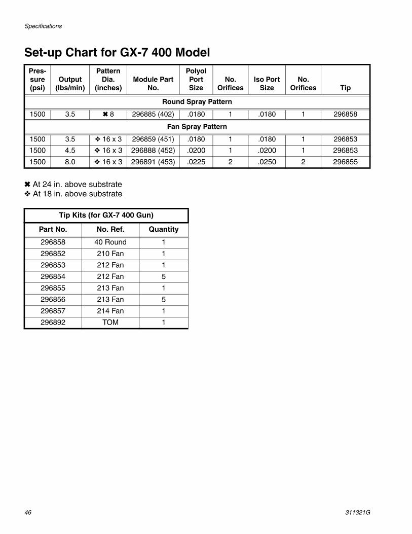
Set-up Chart for GX-7 400 Model
✖ At 24 in. above substrate❖ At 18 in. above substrate
Pres-sure (psi)
Output (lbs/min)
Pattern Dia.
(inches)Module Part
No.
Polyol Port Size
No. Orifices
Iso Port Size
No. Orifices Tip
Round Spray Pattern
1500 3.5 ✖ 8 296885 (402) .0180 1 .0180 1 296858
Fan Spray Pattern
1500 3.5 ❖ 16 x 3 296859 (451) .0180 1 .0180 1 296853
1500 4.5 ❖ 16 x 3 296888 (452) .0200 1 .0200 1 296853
1500 8.0 ❖ 16 x 3 296891 (453) .0225 2 .0250 2 296855
Tip Kits (for GX-7 400 Gun)
Part No. No. Ref. Quantity
296858 40 Round 1
296852 210 Fan 1
296853 212 Fan 1
296854 212 Fan 5
296855 213 Fan 1
296856 213 Fan 5
296857 214 Fan 1
296892 TOM 1

Specifications
311321G 47
GX-7 DI Model Specifications
❄ Actual results may vary due to chemical system characteristics, temperature, pressure, and ratio.
✖ Includes appropriate cleanout drills.
Module/Tip Data for Chemical Sprayed at 2500 PSI
✖ Module Kit Cleanout Drill Ref. No. ❄Pattern❄Output(lbs/min)
Fan Spray Pattern
296900 (#2) 246625
(.086 diameter)
212 12 in. wide 12
206 20 in. wide 22
213 12 in. wide 12
204 20 in. wide 21
296901 (#4) 248892
(.028 diameter)
212 10 in. wide 8
206 24 in. wide 11
204 18 in. wide 10
296903 (#5) 246816
(.018 diameter)
212 11 in. wide 4
213 12 in. wide 4
208 8 in. wide 4
Round Spray Pattern
296903 (#5) 246816
(.018 diameter)
40 4 in. diameter 8
55 7 in. diameter 9.5
70 8 in. diameter 9.75
90 10 in. diameter 9.75
Mix Module Kit
Part No. Size Ref. Quantity
296898 PEEK 018/018 1
296899 PEEK 028/028 1
Module Only
Part No. Size Ref.
296902 #5

Specifications
48 311321G
Tip KitsFor GX-7A and GX-7 DI Models
Tool KitsGX-7A and GX-7 DI models: 296835GX-7 400 model: 296184
Round Tip Kits
Part No. Size Quantity
296708 40 1
296709 46 1
296717 55 5
296710 70 1
296718 70 5
296711 80 1
296719 80 5
296712 90 1
296720 90 5
296694 100 1
296714 100 5
296695 110 1
296696 110 5
296697 125 1
296877 140 1
Flat Tip Kits
Part No.
No. Ref. Qty.
296698 202 1
296699 203 1
296700 204 1
296701 206 1
296702 208 1
296703 209 1
296704 210 1
296715 210 5
296882212.5 SPEC
1
296705 212 1
296716 212 5
296706 213 1
296883213-
SPEC1
296707 215 1

Technical Data
311321G 49
Technical Data
❄ Theoretical: actual results will vary with operating conditions
Category DataAir Supply 100-125 psi (7.9 bars)Maximum Operating Pressure 3500 psi (24 MPa, 240 bar)Maximum Output ❄ GX-7A Model:
40 lbs/min (18 kg/min)GX-7 DI Model:
22 lbs/min (10 kg/min)GX-7 400 Model:
8 lbs/min (3.6 kg/min)Minimum Output ❄ GX-7A Model:
4 lbs/min (1.8 kg/min)GX-7 DI Model:
4 lbs/min (1.8 kg/min)GX-7 400 Model:
3.5 lbs/min (1.6 kg/min)Height 9 in. (23 cm)Length 9.5 in. (24 cm)Width 4.5 in. (11 cm)Weight 3.5 lbs. (1.5 kg)Mixing GX-7A Model:
Internal impingement, airless atomization, solvent-free, mechanically self cleaning
GX-7 DI Model:Internal direct impingement, airless atomiza-tion, solvent-free, mechanically self cleaning
GX-7 400 Model:Internal direct impingement, airless atomiza-tion, solvent-free, mechanically self cleaning
All written and visual data contained in this document reflects the latest product information available at the time of publication. Graco reserves the right to make changes at any time without notice.
This manual contains English. MM 311321
Graco Headquarters: MinneapolisInternational Offices: Belgium, China, Japan, Korea
GRACO INC. P.O. BOX 1441 MINNEAPOLIS, MN 55440-1441Copyright 2005, Graco Inc. is registered to ISO 9001
www.graco.comRevised 12/2008
Graco Standard WarrantyGraco warrants all equipment referenced in this document which is manufactured by Graco and bearing its name to be free from defects in material and workmanship on the date of sale to the original purchaser for use. With the exception of any special, extended, or limited warranty published by Graco, Graco will, for a period of twelve months from the date of sale, repair or replace any part of the equipment determined by Graco to be defective. This warranty applies only when the equipment is installed, operated and maintained in accordance with Graco’s written recommendations.
This warranty does not cover, and Graco shall not be liable for general wear and tear, or any malfunction, damage or wear caused by faulty installation, misapplication, abrasion, corrosion, inadequate or improper maintenance, negligence, accident, tampering, or substitution of non-Graco component parts. Nor shall Graco be liable for malfunction, damage or wear caused by the incompatibility of Graco equipment with structures, accessories, equipment or materials not supplied by Graco, or the improper design, manufacture, installation, operation or maintenance of structures, accessories, equipment or materials not supplied by Graco.
This warranty is conditioned upon the prepaid return of the equipment claimed to be defective to an authorized Graco distributor for verification of the claimed defect. If the claimed defect is verified, Graco will repair or replace free of charge any defective parts. The equipment will be returned to the original purchaser transportation prepaid. If inspection of the equipment does not disclose any defect in material or workmanship, repairs will be made at a reasonable charge, which charges may include the costs of parts, labor, and transportation.
THIS WARRANTY IS EXCLUSIVE, AND IS IN LIEU OF ANY OTHER WARRANTIES, EXPRESS OR IMPLIED, INCLUDING BUT NOT LIMITED TO WARRANTY OF MERCHANTABILITY OR WARRANTY OF FITNESS FOR A PARTICULAR PURPOSE.
Graco’s sole obligation and buyer’s sole remedy for any breach of warranty shall be as set forth above. The buyer agrees that no other remedy (including, but not limited to, incidental or consequential damages for lost profits, lost sales, injury to person or property, or any other incidental or consequential loss) shall be available. Any action for breach of warranty must be brought within two (2) years of the date of sale.
GRACO MAKES NO WARRANTY, AND DISCLAIMS ALL IMPLIED WARRANTIES OF MERCHANTABILITY AND FITNESS FOR A PARTICULAR PURPOSE, IN CONNECTION WITH ACCESSORIES, EQUIPMENT, MATERIALS OR COMPONENTS SOLD BUT NOT MANUFACTURED BY GRACO. These items sold, but not manufactured by Graco (such as electric motors, switches, hose, etc.), are subject to the warranty, if any, of their manufacturer. Graco will provide purchaser with reasonable assistance in making any claim for breach of these warranties.
In no event will Graco be liable for indirect, incidental, special or consequential damages resulting from Graco supplying equipment hereunder, or the furnishing, performance, or use of any products or other goods sold hereto, whether due to a breach of contract, breach of warranty, the negligence of Graco, or otherwise.
FOR GRACO CANADA CUSTOMERSThe Parties acknowledge that they have required that the present document, as well as all documents, notices and legal proceedings entered into, given or instituted pursuant hereto or relating directly or indirectly hereto, be drawn up in English. Les parties reconnaissent avoir convenu que la rédaction du présente document sera en Anglais, ainsi que tous documents, avis et procédures judiciaires exécutés, donnés ou intentés, à la suite de ou en rapport, directement ou indirectement, avec les procédures concernées.
Graco Information TO PLACE AN ORDER, contact your Graco distributor or call to identify the nearest distributor.Phone: 612-623-6921 or Toll Free: 1-800-328-0211 Fax: 612-378-3505