hcc analog monitor hcc design review april 24, 2014 mitch newcomer nandor dressnandt aditya narayan...
TRANSCRIPT
HCC Analog MonitorHCC Design Review
April 24, 2014Mitch Newcomer
Nandor DressnandtAditya NarayanAmogh HalergiDawei Zhang*
* Original design work 2010-2012

HCC Design Review April 24, 2014 2
• Strips System Requirements – • Hybrid Power Regulated 1.2V@ ~10mA with 7 monitored voltages. • Readout Clock. (40MHz)• Command Decoder readout functionality. • Data Output path operational.
• Operation – • Upload Monitored Limits, Masks for Flag warnings/Interlock settings• Monitors Voltages and temp sensors 0-1V, 1.6ms cycle time.• 10 bit monitor data available through Command Decoder request.
• Outputs – • Optional (mask controlled) Flag in Data Stream• Command decoder readout to Normal Data stream extracted by ROD• Selectable HCC output can be used to disable Regulators on the FEIC’s
Analog Monitor
HCC Design Review April 24, 2014 3
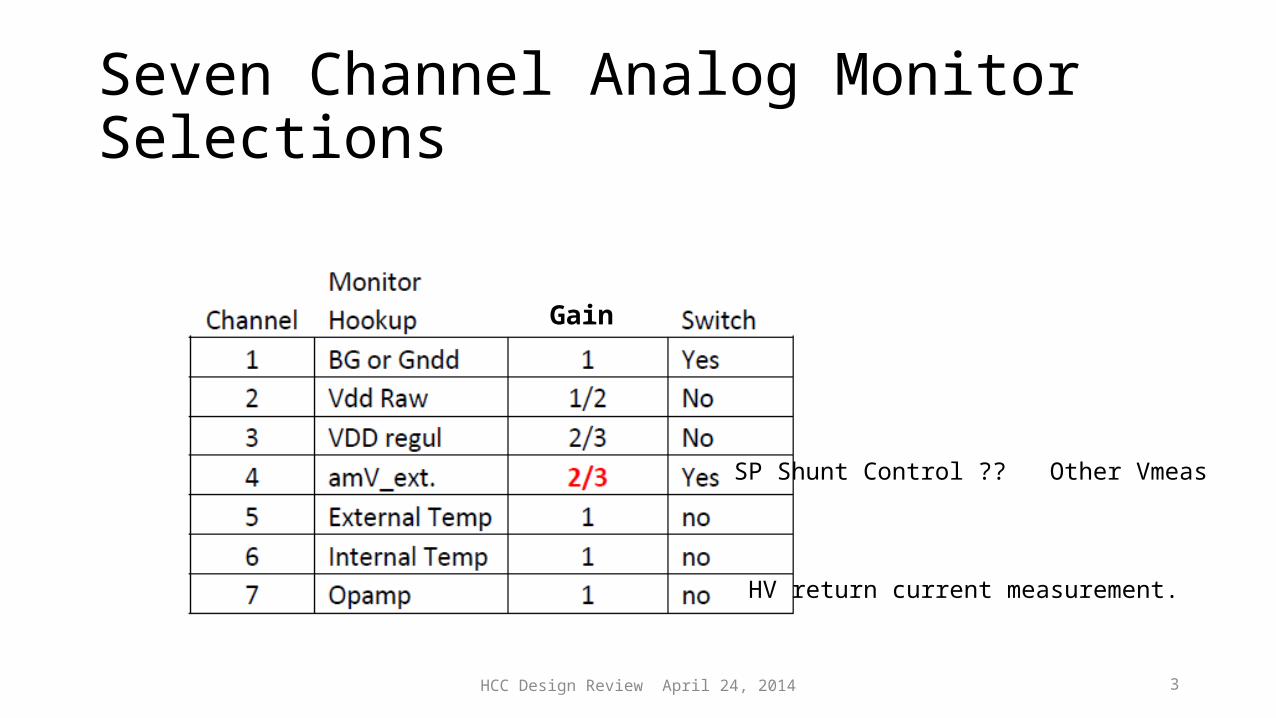
Seven Channel Analog Monitor Selections
SP Shunt Control ?? Other Vmeas
HV return current measurement.
Gain

HCC Design Review April 24, 2014 4
• State machine counter scaled 40MHz clock gives 800ns integrator steps (~1mV)• Zero Volt Reference pad to measure HCC reference. • Counter driven Integrating DAC 0-1000mV provides a common ramp for
all comparator voltage inputs.• When monitored voltage ≥ reference ramp on 2 consecutive steps.
10 bit Counter value Latched• High and Low limits downloaded to HCC registers. Flip flop based
warning flag in status word downloaded with each data packet. • HCC may perform limit based Clock or Regulator Interlock function if
enabled.
Functional Blocks in Words
HCC Design Review April 24, 2014 5
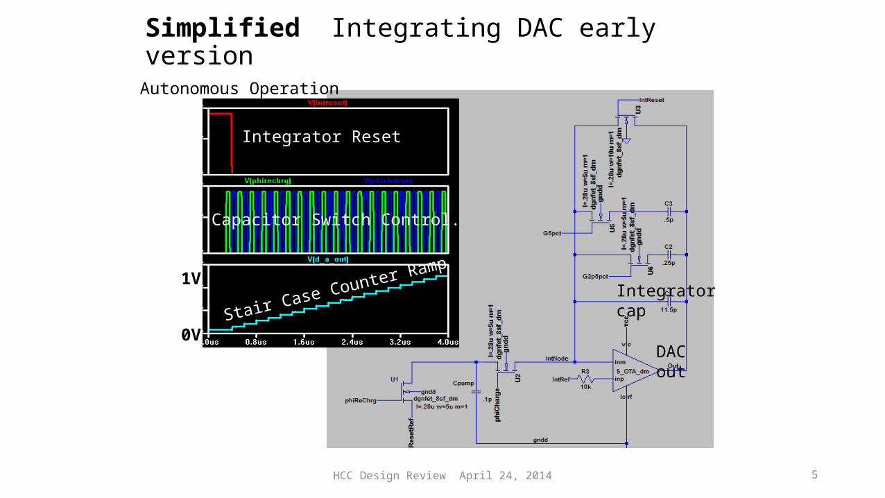
Simplified Integrating DAC early version
Integrator Reset
Capacitor Switch Control.
Stair Case Counter Ramp
DAC out
Integratorcap
0V
1V
Autonomous Operation
HCC Design Review April 24, 2014 6
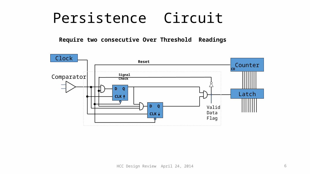
Persistence Circuit
D Q
CLK
D Q
CLK
Latch
CounterCO
Comparator
Clock
Signal Check
Valid Data Flag
Reset
Require two consecutive Over Threshold Readings

HCC Design Review April 24, 2014 7
Limit Logic Counter
Upper Limit
Lower Limit
D(0:8)
D(0:8)
D(0:8)
D Q
CLK
D Q
CLK
Data Valid Flag
(Reset at start of each Ramp)
SR bit “Exceeds Hi Limit”
SR bit “Below Low Limit”
Minimal logic exploits the counter scheme
If Lower Limit Matches Counterafter “Valid Data” Set Warning Flag
If Upper Limit Matches Counterbefore “Valid Data” Set Warning Flag
HCC Design Review April 24, 2014 8
Measurement Accessories
• NTC temp sensor• Diode Temp Sensor• HV return Current Measurement
HCC Design Review April 24, 2014 9
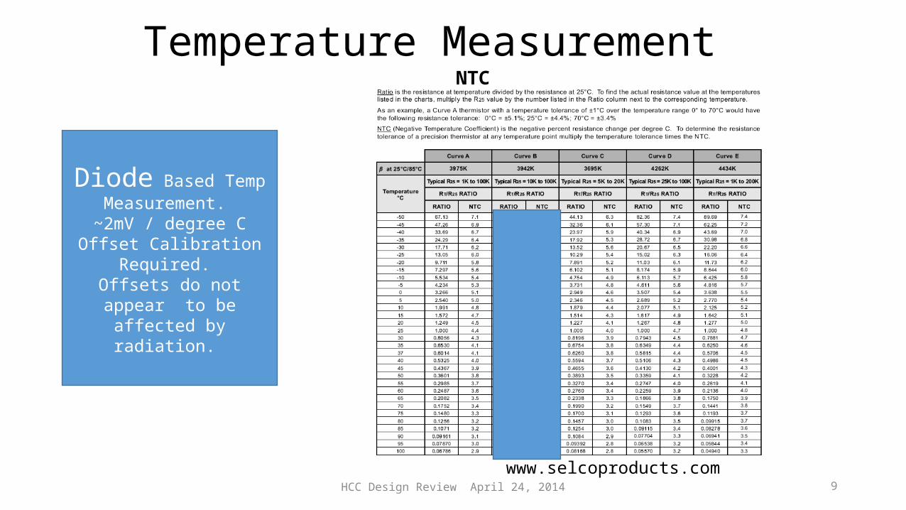
Temperature Measurement
www.selcoproducts.com
NTC
Diode Based Temp Measurement.
~2mV / degree COffset Calibration Required. Offsets do not appear to be
affected by radiation.

HCC Design Review April 24, 2014 10
10K NTC Temp Meas. Example
-50 -25 0 25 50 75 1000
100200300400500600700
HCC Measured Voltage
Celcius
mV
-50 -25 0 25 50 75 1000123456789
dV / dt (mV/C)
Celciusm
V
HCC Monitor NTC Thermister 10K @ 25CExternal 75K resistor. Bandgap driven Ref.
dV/dt > ~6mV -30C to 5C
1µA leakage ~35mV offset Need lower R NTC
HCC Design Review April 24, 2014 11
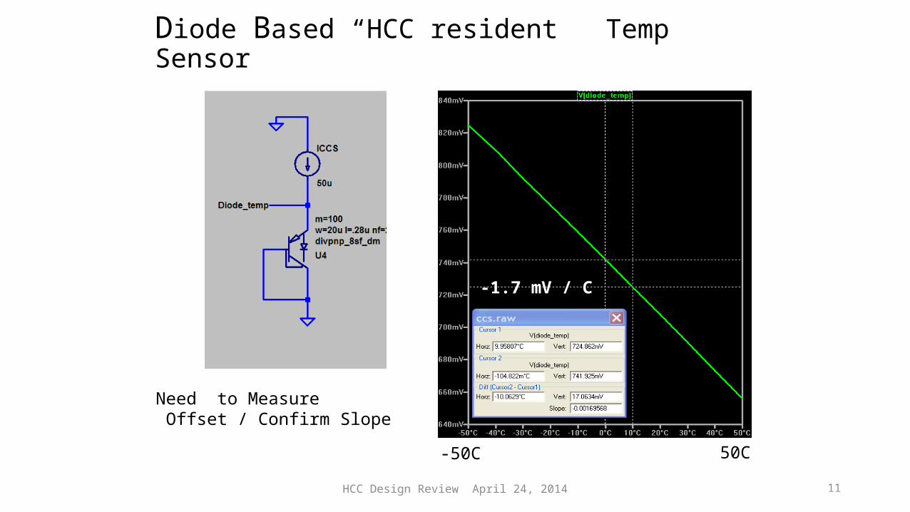
Diode Based “HCC resident ” Temp Sensor
-1.7 mV / C
-50C 50C
Need to Measure Offset / Confirm Slope
HCC Design Review April 24, 2014 12
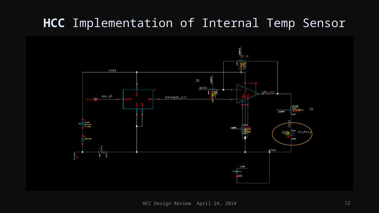
HCC Implementation of Internal Temp Sensor

HCC Design Review April 24, 2014 13
Simulation of Implemented Diode Temp Module
-30 -25 -20 -15 -10 -5 0 5 10 15 20 25 30 35 40 45 50 55 60 65 70700.0
720.0
740.0
760.0
780.0
800.0
820.0
840.0
860.0
Vout
VoutLinear Vout
Temp Vout -30 851.8
-25 845.4-20 838.9-15 832.4-10 825.9
-5 819.30 812.65 806.0
10 799.215 792.520 785.625 778.730 771.735 764.640 757.445 750.150 742.8
1.33mV/0C
mV
oC

HCC Design Review April 24, 2014 14
Sensor Return Current Amplifier
SS0 0-5µA -> 19KΩSS1 0-500µA ->1.8KΩSS2 0-2.5mA -> 300ΩSS3 0-5mA -> 120
Inverting Amp Input assumesCurrent pulled from a negative voltage ource.
Current from Negatively Biased Sensor. Note that protection diodes are a free line of defense if the opamp dies. Easily can handle 5mA.
Default Turn on All swiches Hi ‘F’

HCC Design Review April 24, 2014 15
OpAmp adapted for 0utput current >5mA
PMOS Inputfollowers
HCC Design Review April 24, 2014 16
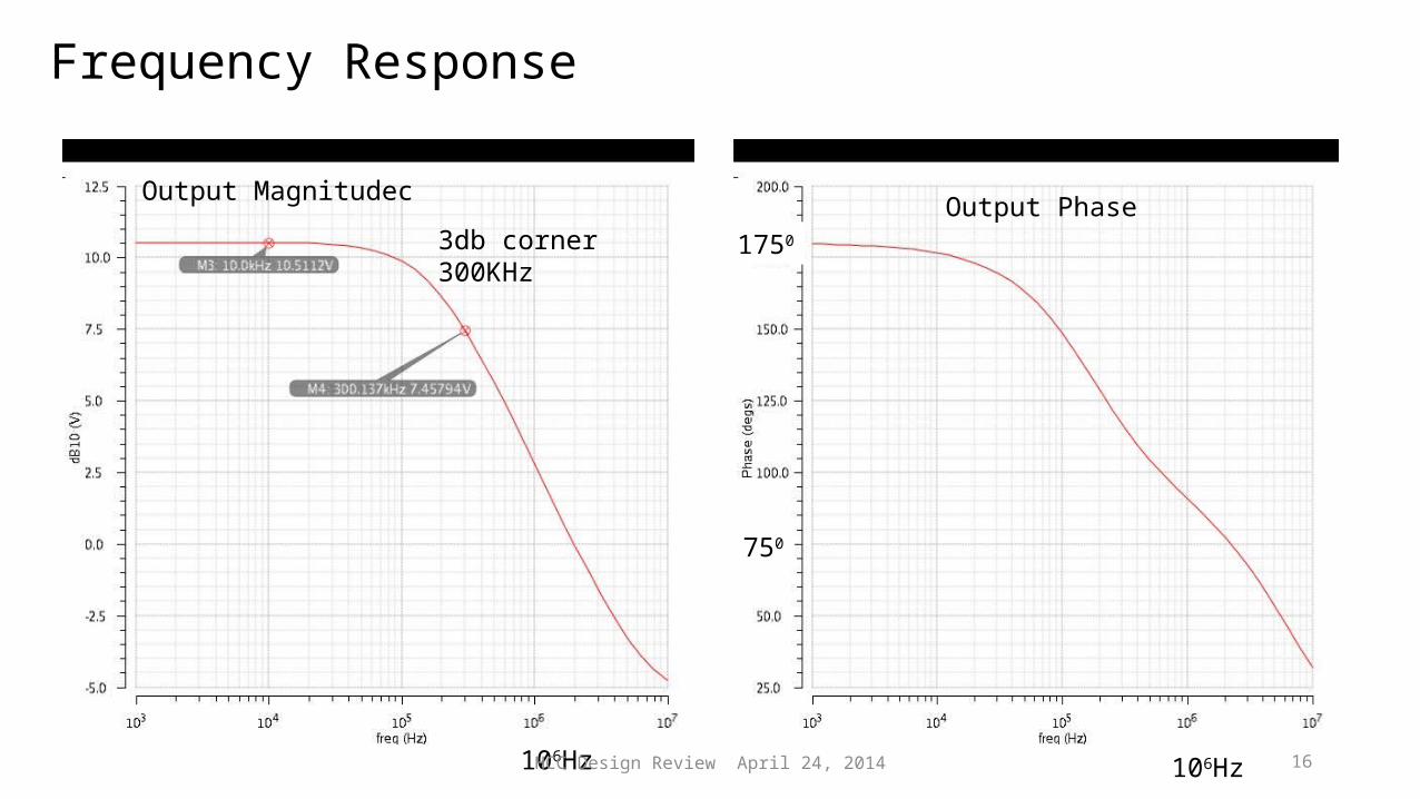
Frequency Response
3db corner300KHz
1750
750
106Hz106Hz
Output Magnitudec Output Phase
HCC Design Review April 24, 2014 17
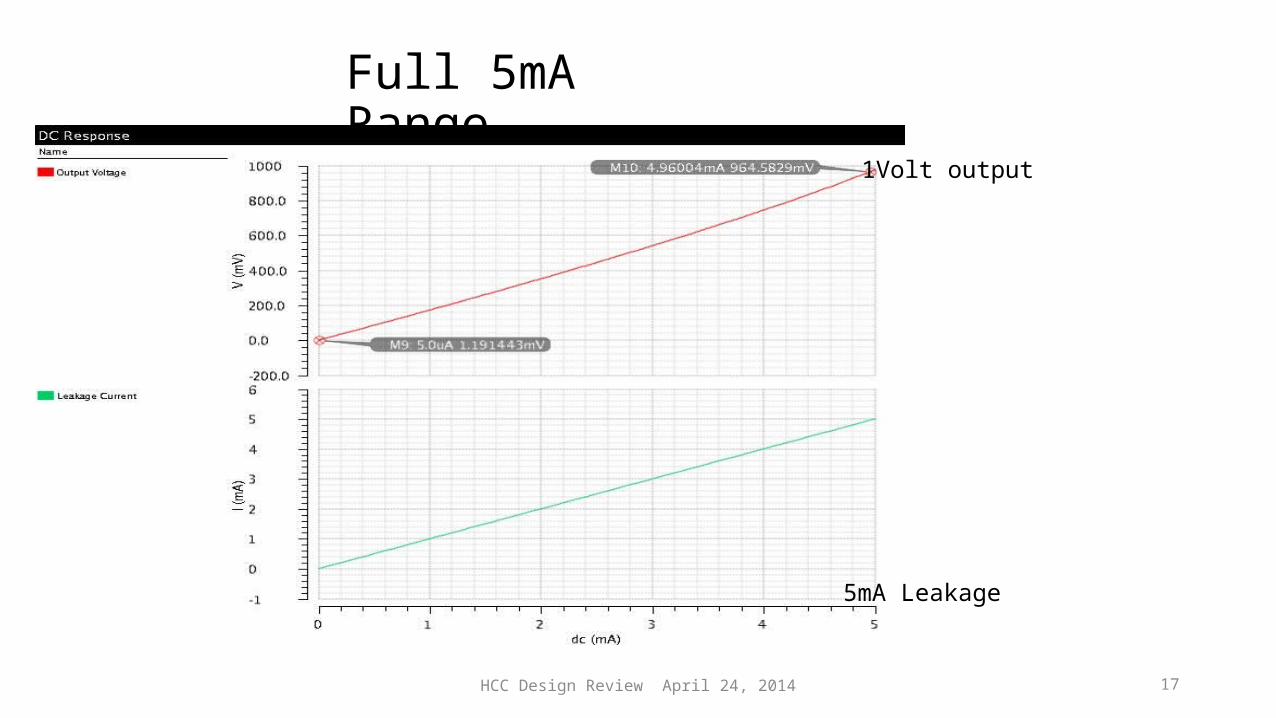
Full 5mA Range
5mA Leakage
1Volt output
HCC Design Review April 24, 2014 18
Summary
The Autonomous monitor provides and automated measurement system able to monitor: HCC voltages Vraw, Vregulator, Vbandgap, 0V hybrid, Internal and external temperature, current returned from the Sensor and an optional external input Programmed limit sensing can Provoke an Action error flag, turn off hybrid clocks or even the ABCn regulator (both require 2 different enable bits in the HCC). Each of the channels may be masked to eliminate Action.