high cell-density fermentation of escherichia coli · high cell-density fermentation of escherichia...
TRANSCRIPT
1
High cell-density fermentation of Escherichia coli
This is a 5-day protocol for high cell-density fermentation of E. coli strains and overnightover-expression of (a) target protein(s) using a computer controlled fed-batch procedure.
Protocol in short
Day 1 Assembly of the fermenter vesselPreparation and autoclavation of the fermenter vessel
• Preparation for autoclaving• Calibration of the pH probe (external)• Autoclaving the fermenter vessel
late afternoon Preparation of the starter culture
Day 2 early morning Preparation of inoculation culturesPreparation of the fermenter vessel for cultivation
early morningafternoonafternoonafternoon
• Polarizing the DO probe (for at least 6 hours)• Recalibration of the pH probe (internal)• Setting the fermentation parameters• Calibration of the DO probe
late afternoon Inoculation of the fermenter vessel and start of the batch phase
Day 3 early morning Start of the fed-batch phase• Start of the feeding protocol
late afternoon Induction of protein expression• Start of the temperature profile• IPTG induction
Day 4 Harvesting of the cells• Harvesting the cells• Cleaning the feed tubing• Autoclaving the fermenter vessel
Day 5 Cleaning of the fermenter vessel
This protocol has been set up and optimized by Anni Linden and Rajesh Kumar Singh and isbased on Korz et al. (1995) J. Biotechnol. 39, 59-65.
Arie Geerlof - EMBL Hamburg 29 January 2008
2
Day 1 Preparation of the fermentation vessel and starter culture
1. Assembly of the fermenter vessel
When necessary grease the O-rings of the fermenter vessel with high vacuum grease (DowCorning).
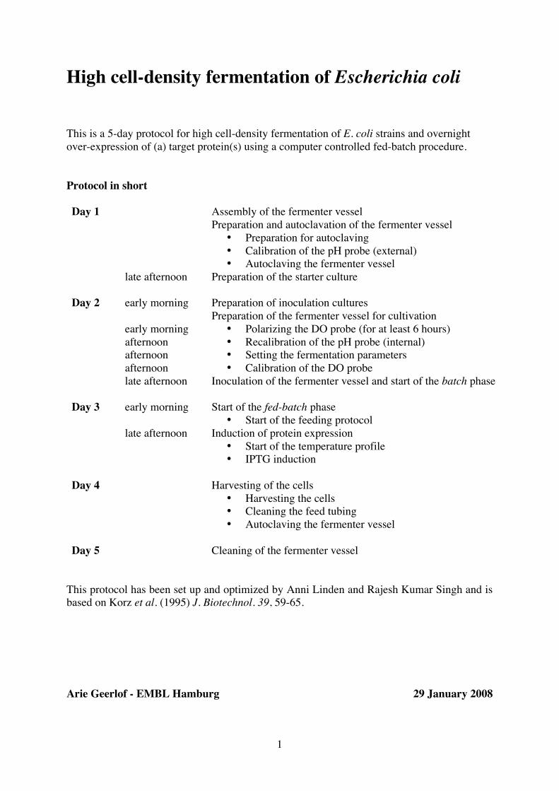
1.1. Reaction vessel
1. Hang the reaction vessel in the stand by fixing the three supports with the associatedscrews (Photo's 1 - 4)
2. Attach the two hose connectors for the water-cooling to the reaction vessel (Photo's 5and 6).

3
1.2. Vessel lid (or head plate)
The following parts and probes are connected to the vessel lid:
4-way sampler DO probe (dissolved oxygen)Exhaust cooler Level probeMotor pH probeSample portSampling tubeSpargerTemperature sensor tube
The preferred position of the different parts and probes is indicated in Photo 7.

4
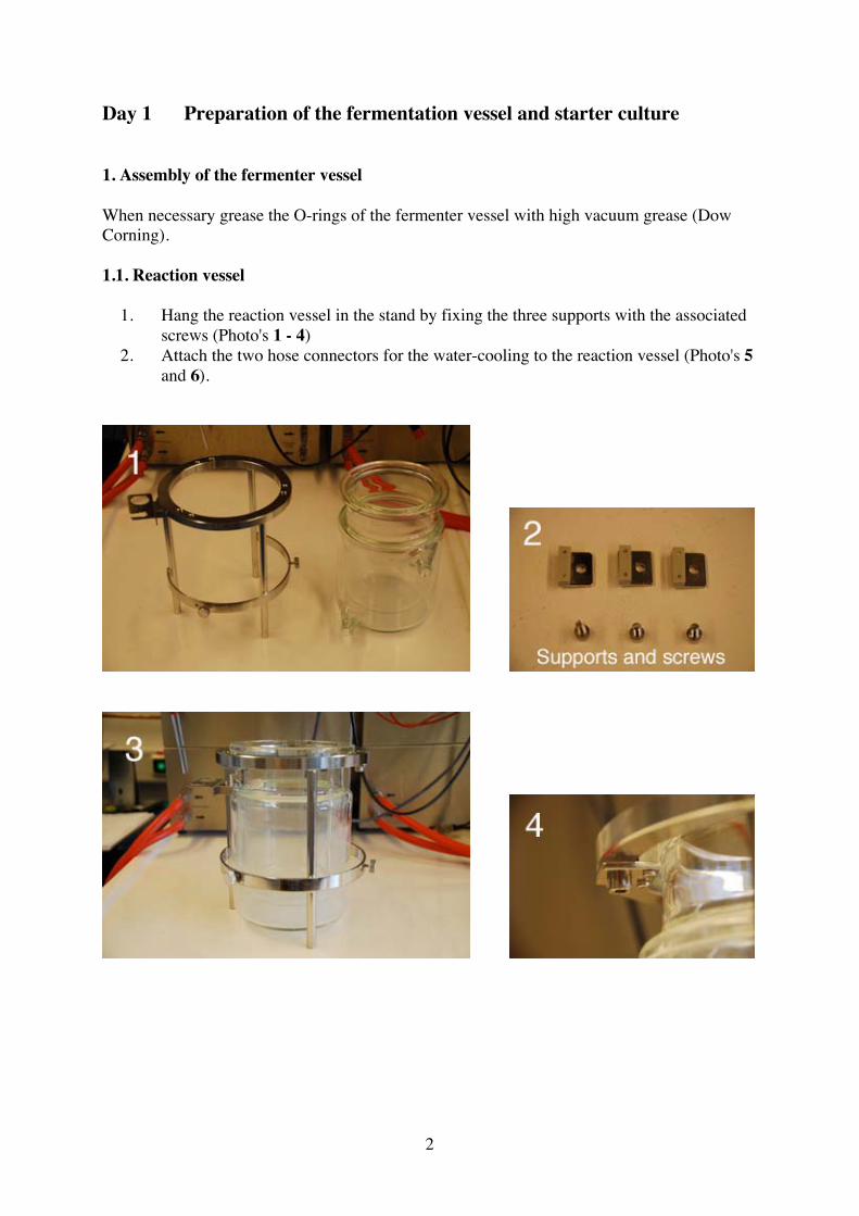
3. Attach the sparger to the underside of the vessel lid. Remove the hexagonal screwand push the top of the sparger through the vessel lid. Tighten the hexagonal screw atthe topside of the lid (using spanner no 13). The sparger has to be positioned in themiddle of the reaction vessel and just below the bottom impeller of the stirrer (Photo8).
4. Repeat step 3 with the temperature sensor tube (Photo 8).5. Place the vessel lid on top of the reaction vessel (as shown in Photo 9) and attach to
the stand by tightening the 3 large (attached) screws.6. Attach the exhaust cooler to the vessel lid (Photo 10). Place the outlet tube connector
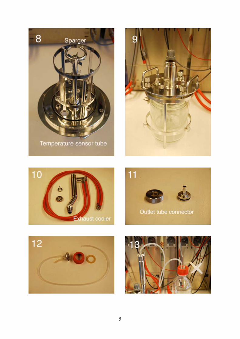
on the top of the cooler and fix it with the metal ring (Photo 11 and 13). Attach apiece of silicon tubing to the outlet and connect the other end with a 1-L bottle(Photo's 12 and 13). Place a large filter on the bottle outlet tubing. Connect the redtubing to the fermenter unit as shown in Photo 14.
7. Attach the following parts to the vessel lid (Photo's 15 and 16):• 4-way sampler. Push the sampler through the hole and fix it with the metal
ring.• Level probe. Push the probe through the hole and tighten with the hexagonal
screw.• Sample port. Place a new white rubber septum into the sample port opening
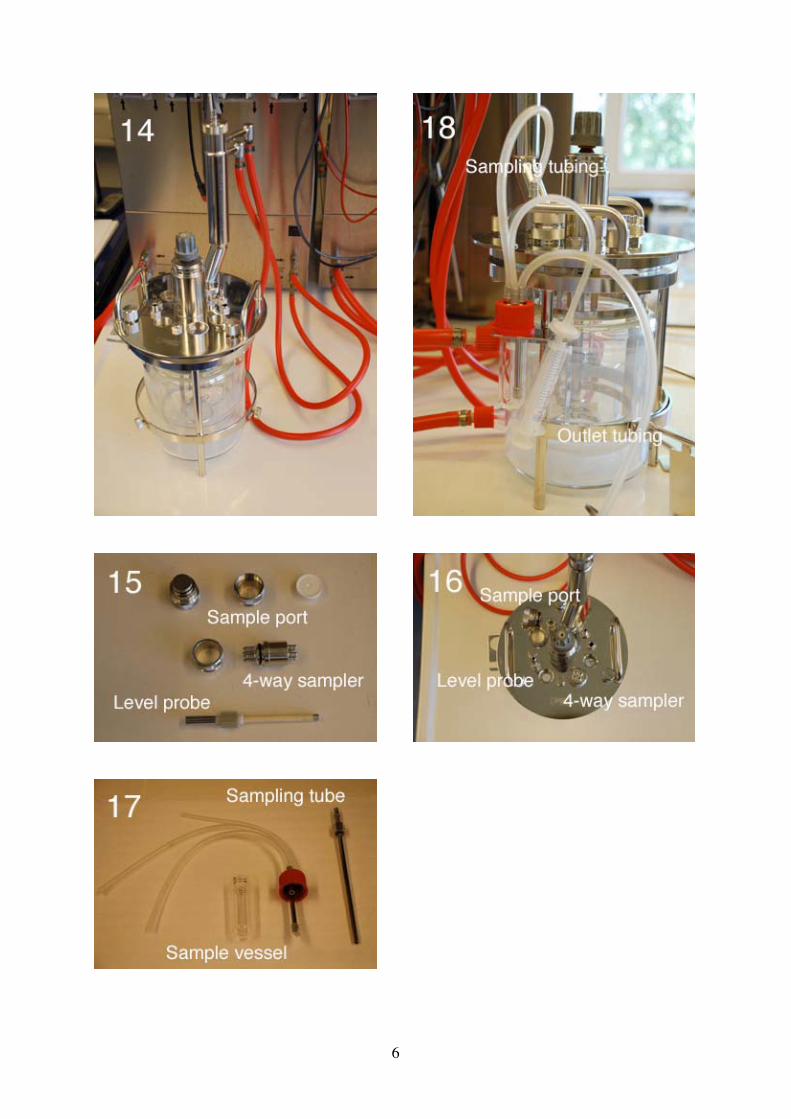
and fix it with the metal ring. Cover the septum with the metal plug.8. The manual sampler consists of the sampling tube and the sample vessel (Photo 17).
Push the sampling tube through the hole in the vessel lid as far as it goes and tightenthe hexagonal screw. The outlet is connected to the sample vessel with silicon tubingas shown in Photo 18. The lid of the sample vessel has 3 outlets:
• One outlet with a long tube inside the sample vessel. This is for the outlettubing.
• One outlet with a short tube inside the sample vessel. Connect the tubingcoming from the sampling tube to this outlet (sampling tubing).
• One outlet without an inside tube. Attach a piece if thinner silicon tubing tothe outlet and a small sterile filter and a 10-ml plastic syringe to the other end.
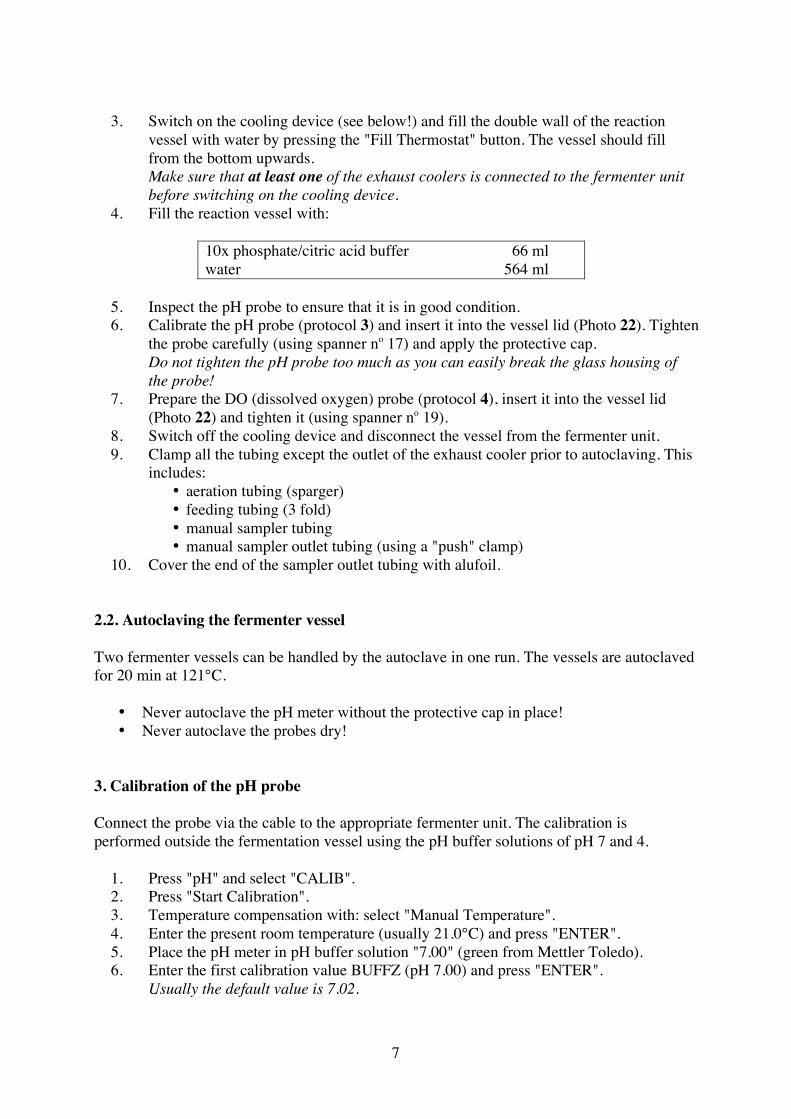
9. Attach the bottle rack to the stand and place in order (left to right) an empty 250-mlbottle, a brown 250-ml bottle with about 50 ml Antifoam 204 (Sigma), and an empty250-ml bottle in the rack. Screw lids with one long (feed) and one short (outlet)silicon tubing on top of the two empty bottles (Photo 19). Connect the long feedtubing in order to the 4-way sampler. Place dummy tubing on the remainingconnection (Photo 20). Place a small filter on the outlet tubing.
10. Attach a short piece of silicon tubing to the aeration tube (top of the sparger) andplace a large sterile filter on the inlet.
2. Autoclavation
2.1. Preparation for autoclaving
1. Switch on all 4 fermenter units before switching on the central DCU tower bypressing the green "MAINS" button.
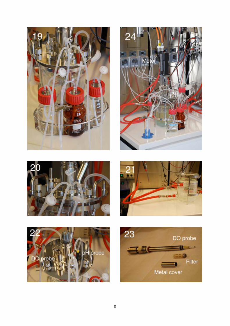
2. Connect the hose connectors to the thermostat of the fermenter unit (Photo 21).
5
6
7
3. Switch on the cooling device (see below!) and fill the double wall of the reactionvessel with water by pressing the "Fill Thermostat" button. The vessel should fillfrom the bottom upwards.Make sure that at least one of the exhaust coolers is connected to the fermenter unitbefore switching on the cooling device.
4. Fill the reaction vessel with:
10x phosphate/citric acid buffer 66 mlwater 564 ml
5. Inspect the pH probe to ensure that it is in good condition.6. Calibrate the pH probe (protocol 3) and insert it into the vessel lid (Photo 22). Tighten
the probe carefully (using spanner no 17) and apply the protective cap.Do not tighten the pH probe too much as you can easily break the glass housing ofthe probe!
7. Prepare the DO (dissolved oxygen) probe (protocol 4), insert it into the vessel lid(Photo 22) and tighten it (using spanner no 19).
8. Switch off the cooling device and disconnect the vessel from the fermenter unit.9. Clamp all the tubing except the outlet of the exhaust cooler prior to autoclaving. This
includes:• aeration tubing (sparger)• feeding tubing (3 fold)• manual sampler tubing• manual sampler outlet tubing (using a "push" clamp)
10. Cover the end of the sampler outlet tubing with alufoil.
2.2. Autoclaving the fermenter vessel
Two fermenter vessels can be handled by the autoclave in one run. The vessels are autoclavedfor 20 min at 121°C.
• Never autoclave the pH meter without the protective cap in place!• Never autoclave the probes dry!
3. Calibration of the pH probe
Connect the probe via the cable to the appropriate fermenter unit. The calibration isperformed outside the fermentation vessel using the pH buffer solutions of pH 7 and 4.
1. Press "pH" and select "CALIB".2. Press "Start Calibration".3. Temperature compensation with: select "Manual Temperature".4. Enter the present room temperature (usually 21.0°C) and press "ENTER".5. Place the pH meter in pH buffer solution "7.00" (green from Mettler Toledo).6. Enter the first calibration value BUFFZ (pH 7.00) and press "ENTER".
Usually the default value is 7.02.
8
9
7. Wait until the electrode (ELEC) is stable and press "ENTER".8. Rinse the pH meter with water, dry with a tissue and place in pH buffer solution
"4.01" (red from Mettler Toledo).9. Enter the second calibration value BUFFS (pH 4.01) and press "ENTER".
Usually the default value is 4.02.10. Wait until the electrode (ELEC) is stable and press "ENTER".11. Temperature compensation with: select "Manual Temperature".12. Enter the present room temperature (usually 21.0°C) and press "ENTER".13. Press "EXIT".14. Rinse the pH meter with water, dry with a tissue and insert it into the vessel lid.
4. Preparation of the DO probe
1. Put on a pair of latex gloves.The sensor and filter should not be touched with the bare hands.
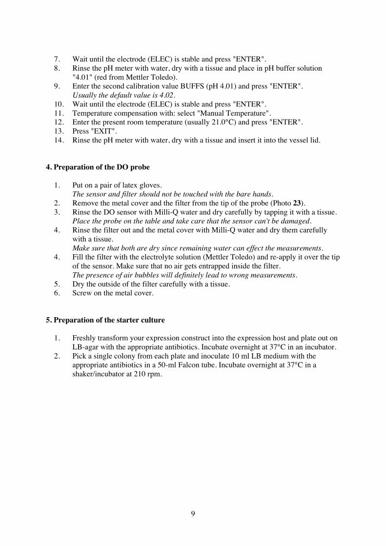
2. Remove the metal cover and the filter from the tip of the probe (Photo 23).3. Rinse the DO sensor with Milli-Q water and dry carefully by tapping it with a tissue.
Place the probe on the table and take care that the sensor can't be damaged.4. Rinse the filter out and the metal cover with Milli-Q water and dry them carefully
with a tissue.Make sure that both are dry since remaining water can effect the measurements.
4. Fill the filter with the electrolyte solution (Mettler Toledo) and re-apply it over the tipof the sensor. Make sure that no air gets entrapped inside the filter.The presence of air bubbles will definitely lead to wrong measurements.
5. Dry the outside of the filter carefully with a tissue.6. Screw on the metal cover.
5. Preparation of the starter culture
1. Freshly transform your expression construct into the expression host and plate out onLB-agar with the appropriate antibiotics. Incubate overnight at 37°C in an incubator.
2. Pick a single colony from each plate and inoculate 10 ml LB medium with theappropriate antibiotics in a 50-ml Falcon tube. Incubate overnight at 37°C in ashaker/incubator at 210 rpm.
10
Day 2 Preparation of the fermenter vessel for cultivation and inoculation
6. Preparation of the inoculation cultures
In the morning, inoculate 3 x 10 ml LB medium with the appropriate antibiotics in 50-mlFalcon tubes with 100 µl of the overnight culture. Incubate for at least 8 hours at 37°C in ashaker/incubator at 210 rpm.
7. Preparation of the fermenter vessel for cultivation
1. In the morning, connect the DO probe to the appropriate fermenter unit and wait forat least 6 hours before using it. This time period is necessary to polarize the probe.During the polarization process the fermenter units and the central DCU tower needto be switch on.
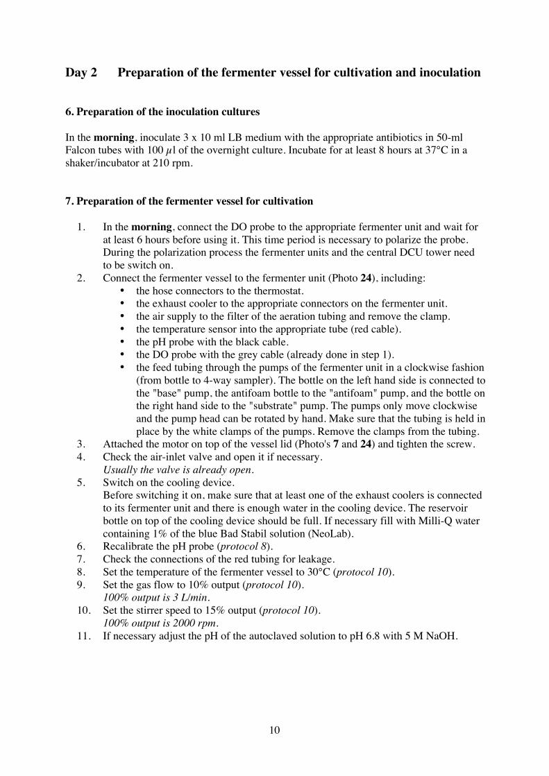
2. Connect the fermenter vessel to the fermenter unit (Photo 24), including:• the hose connectors to the thermostat.• the exhaust cooler to the appropriate connectors on the fermenter unit.• the air supply to the filter of the aeration tubing and remove the clamp.• the temperature sensor into the appropriate tube (red cable).• the pH probe with the black cable.• the DO probe with the grey cable (already done in step 1).• the feed tubing through the pumps of the fermenter unit in a clockwise fashion
(from bottle to 4-way sampler). The bottle on the left hand side is connected tothe "base" pump, the antifoam bottle to the "antifoam" pump, and the bottle onthe right hand side to the "substrate" pump. The pumps only move clockwiseand the pump head can be rotated by hand. Make sure that the tubing is held inplace by the white clamps of the pumps. Remove the clamps from the tubing.
3. Attached the motor on top of the vessel lid (Photo's 7 and 24) and tighten the screw.4. Check the air-inlet valve and open it if necessary.
Usually the valve is already open.5. Switch on the cooling device.
Before switching it on, make sure that at least one of the exhaust coolers is connectedto its fermenter unit and there is enough water in the cooling device. The reservoirbottle on top of the cooling device should be full. If necessary fill with Milli-Q watercontaining 1% of the blue Bad Stabil solution (NeoLab).
6. Recalibrate the pH probe (protocol 8).7. Check the connections of the red tubing for leakage.8. Set the temperature of the fermenter vessel to 30°C (protocol 10).9. Set the gas flow to 10% output (protocol 10).
100% output is 3 L/min.10. Set the stirrer speed to 15% output (protocol 10).
100% output is 2000 rpm.11. If necessary adjust the pH of the autoclaved solution to pH 6.8 with 5 M NaOH.

11
12. Complete the medium by adding the following components:
70% glucose 27.9 mlMgSO4 solution 1.58 ml100x Trace metal solution 6.60 mlThiamine solution 0.15 mlappropriate antibiotics (1000x) 0.66 ml (each)
12. Calibrate the DO probe (protocol 9).13. Replace the empty bottle on the left hand side in the bottle rack with a 250-ml bottle
containing at least 150 ml ammonium hydroxide (25% ammonia).Take care not to inhale ammonia vapour when changing the bottles.
14. Fill the tubing with ammonia by setting the "Base" pump to "man" till a fewcentimeters from the end (of the tubing).The ammonia solution should be connected to the "Base" pump.
15. Set the pH of the culture medium to "6.8" (protocol 10).16. Set the "Base" pump to "auto".17. Fill the appropriate tubing with antifoam by setting the "Antifoam" pump to "man".18. Set the parameters and set point for the pO2 (protocol 10).19. Switch on the MFCS/win software and define the fermentation batch. Then set the
batch to "Start".
8. Recalibration of the pH probe
The recalibration is performed inside the fermentation vessel correcting the pH value forchanges during autoclaving.
1. Take an approx. 5-ml sample from the autoclaved buffer in the fermenter vessel usingthe manual sampler (protocol 11).
2. Determine the pH value using an external (calibrated) pH meter.3. Press "pH" and select "CALIB".4. Press "Start Re-calibration".5. Select "pH", enter the in step 2 determined value, and press "OK".6. Press "ENTER".7. Press "EXIT".
9. Calibration of the DO probe
The calibration of the DO (dissolved oxygen) probe is necessary to set the "0%" and "100%"saturation levels.
1. Press "STIR" and change "OUT" to 80% (is 1600 rpm).2. Press "EXIT".3. Press "GASF" and change "OUT" to 100% (is 3 L/min).4. Press "EXIT".5. Press "pO2" and select "CALIB".6. Wait for 5 min to saturate the medium with air.
12
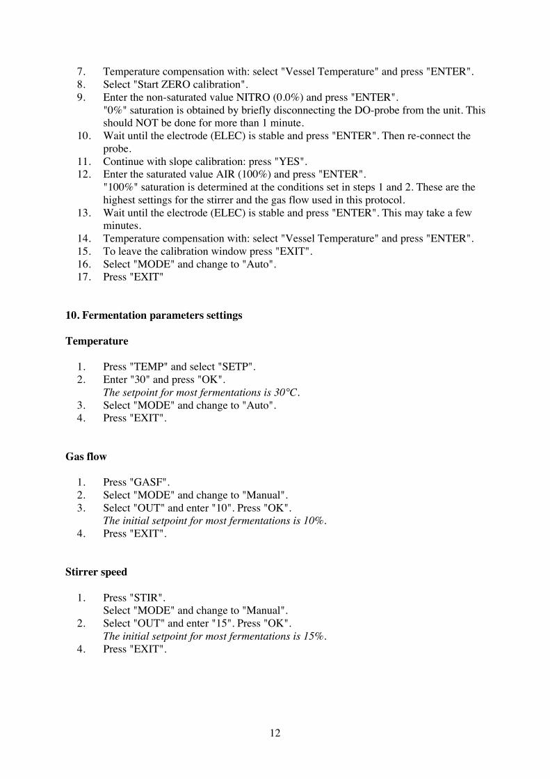
7. Temperature compensation with: select "Vessel Temperature" and press "ENTER".8. Select "Start ZERO calibration".9. Enter the non-saturated value NITRO (0.0%) and press "ENTER".
"0%" saturation is obtained by briefly disconnecting the DO-probe from the unit. Thisshould NOT be done for more than 1 minute.
10. Wait until the electrode (ELEC) is stable and press "ENTER". Then re-connect theprobe.
11. Continue with slope calibration: press "YES".12. Enter the saturated value AIR (100%) and press "ENTER".
"100%" saturation is determined at the conditions set in steps 1 and 2. These are thehighest settings for the stirrer and the gas flow used in this protocol.
13. Wait until the electrode (ELEC) is stable and press "ENTER". This may take a fewminutes.
14. Temperature compensation with: select "Vessel Temperature" and press "ENTER".15. To leave the calibration window press "EXIT".16. Select "MODE" and change to "Auto".17. Press "EXIT"
10. Fermentation parameters settings
Temperature
1. Press "TEMP" and select "SETP".2. Enter "30" and press "OK".
The setpoint for most fermentations is 30°C.3. Select "MODE" and change to "Auto".4. Press "EXIT".
Gas flow
1. Press "GASF".2. Select "MODE" and change to "Manual".3. Select "OUT" and enter "10". Press "OK".
The initial setpoint for most fermentations is 10%.4. Press "EXIT".
Stirrer speed
1. Press "STIR".Select "MODE" and change to "Manual".
2. Select "OUT" and enter "15". Press "OK".The initial setpoint for most fermentations is 15%.
4. Press "EXIT".

13
pH
1. Press "pH" and select "SETP".2. Enter "6.8" and press "OK".
The setpoint for most E. coli fermentations is pH 6.8.3. Select "MODE" and change to "Auto".4. Press "EXIT".
Dissolved oxygen (pO2)
1. Press "pO2" and select "PARAM".2. Enter "9" and press "OK".3. Enter the following values:
minimal maximalStirrer 15% 80%Gas flow 40% 100%O2 0% 100%
Do not change any of the other values in this window. They have been optimized toregulate the parameter control optimally.
4. Press "EXIT" and select "SETP".5. Enter "30" and press "OK".
The setpoint for most fermentations is between 20 and 40%.6. Select "MODE" and change to "Auto".
Since the regulation of the dissolved oxygen level (pO2) is performed via the stirrerspeed, the gas flow, and oxygen supply the mode settings for these parameters willautomatically change to "Cascade".
7. Press "EXIT".
A quick overview of the fermention settings can be obtained under "Controller" (see alsoAppendix 2).
For the batch phase the settings should read:
TEMP JTMP STIR pH pO2 FOAM SUBS GASF O2ENauto cascade cascade auto auto manual off cascade cascade
30.0°C 6.80 30%
To return to the main page press "Main".
11. Taking a sample using the manual sampler (Photo 18)
In order not to compromise the sterility of the content of the fermenter vessel, samples shouldbe taken using the following protocol. The more reliable results are obtained when twosamples are taken sequentially. The first sample (of approx. 1 ml) will be used to "clean" thetubing and the sample vessel. The second sample (1-5 ml) is the real sample and should be
14
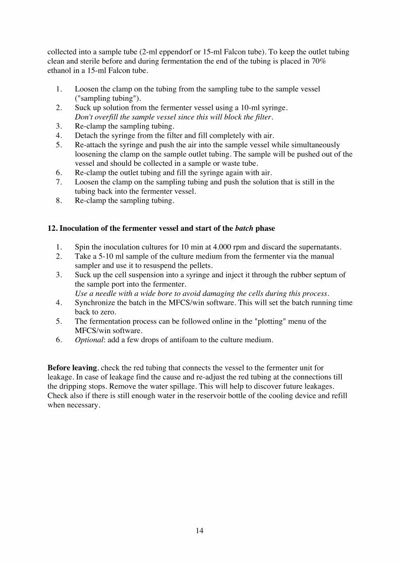
collected into a sample tube (2-ml eppendorf or 15-ml Falcon tube). To keep the outlet tubingclean and sterile before and during fermentation the end of the tubing is placed in 70%ethanol in a 15-ml Falcon tube.
1. Loosen the clamp on the tubing from the sampling tube to the sample vessel("sampling tubing").
2. Suck up solution from the fermenter vessel using a 10-ml syringe.Don't overfill the sample vessel since this will block the filter.
3. Re-clamp the sampling tubing.4. Detach the syringe from the filter and fill completely with air.5. Re-attach the syringe and push the air into the sample vessel while simultaneously
loosening the clamp on the sample outlet tubing. The sample will be pushed out of thevessel and should be collected in a sample or waste tube.
6. Re-clamp the outlet tubing and fill the syringe again with air.7. Loosen the clamp on the sampling tubing and push the solution that is still in the
tubing back into the fermenter vessel.8. Re-clamp the sampling tubing.
12. Inoculation of the fermenter vessel and start of the batch phase
1. Spin the inoculation cultures for 10 min at 4.000 rpm and discard the supernatants.2. Take a 5-10 ml sample of the culture medium from the fermenter via the manual
sampler and use it to resuspend the pellets.3. Suck up the cell suspension into a syringe and inject it through the rubber septum of
the sample port into the fermenter.Use a needle with a wide bore to avoid damaging the cells during this process.
4. Synchronize the batch in the MFCS/win software. This will set the batch running timeback to zero.
5. The fermentation process can be followed online in the "plotting" menu of theMFCS/win software.
6. Optional: add a few drops of antifoam to the culture medium.
Before leaving, check the red tubing that connects the vessel to the fermenter unit forleakage. In case of leakage find the cause and re-adjust the red tubing at the connections tillthe dripping stops. Remove the water spillage. This will help to discover future leakages.Check also if there is still enough water in the reservoir bottle of the cooling device and refillwhen necessary.
15
Day 3 Start of the fed-batch phase and induction of protein expression
13. End of the batch phase
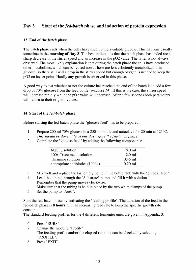
The batch phase ends when the cells have used up the available glucose. This happens usuallysometime in the morning of Day 3. The best indications that the batch phase has ended are asharp decrease in the stirrer speed and an increase in the pO2 value. The latter is not alwaysobserved. The most likely explanation is that during the batch phase the cells have producedother metabolites, which can be reused now. These are less efficiently metabolized thanglucose, so there still will a drop in the stirrer speed but enough oxygen is needed to keep thepO2 on its set point. Hardly any growth is observed in this phase.
A good way to test whether or not the culture has reached the end of the batch is to add a fewdrop of 70% glucose from the feed bottle (protocol 14). If this is the case, the stirrer speedwill increase rapidly while the pO2 value will decrease. After a few seconds both parameterswill return to their original values.
14. Start of the fed-batch phase
Before starting the fed-batch phase the "glucose feed" has to be prepared.
1. Prepare 200 ml 70% glucose in a 250-ml bottle and autoclave for 20 min at 121°C.This should be done at least one day before the fed-batch phase.
2. Complete the "glucose feed" by adding the following components:
MgSO4 solution 8.0 ml100x Trace metal solution 2.0 mlThiamine solution 0.45 mlappropriate antibiotics (1000x) 0.20 ml
3. Mix well and replace the last empty bottle in the bottle rack with the "glucose feed".4. Lead the tubing through the "Substrate" pump and fill it with solution.
Remember that the pump moves clockwise.Make sure that the tubing is held in place by the two white clamps of the pump.
5. Set the pump to "Auto".
Start the fed-batch phase by activating the "feeding profile". The duration of the feed in thefed-batch phase is 8 hours with an increasing feed rate to keep the specific growth rateconstant.The standard feeding profiles for the 4 different fermenter units are given in Appendix 3.
6. Press "SUBS".7. Change the mode to "Profile".
The feeding profile and/or the elapsed run time can be checked by selecting"PROFILE".
8. Press "EXIT".
16
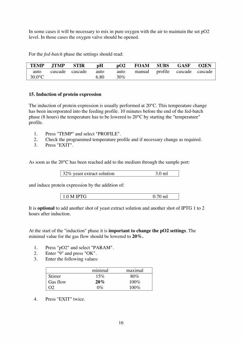
In some cases it will be necessary to mix in pure oxygen with the air to maintain the set pO2level. In those cases the oxygen valve should be opened.
For the fed-batch phase the settings should read:
TEMP JTMP STIR pH pO2 FOAM SUBS GASF O2ENauto cascade cascade auto auto manual profile cascade cascade
30.0°C 6.80 30%
15. Induction of protein expression
The induction of protein expression is usually performed at 20°C. This temperature changehas been incorporated into the feeding profile. 10 minutes before the end of the fed-batchphase (8 hours) the temperature has to be lowered to 20°C by starting the "temperature"profile.
1. Press "TEMP" and select "PROFILE".2. Check the programmed temperature profile and if necessary change as required.3. Press "EXIT".
As soon as the 20°C has been reached add to the medium through the sample port:
32% yeast extract solution 3.0 ml
and induce protein expression by the addition of:
1.0 M IPTG 0.70 ml
It is optional to add another shot of yeast extract solution and another shot of IPTG 1 to 2hours after induction.
At the start of the "induction" phase it is important to change the pO2 settings. Theminimal value for the gas flow should be lowered to 20%.
1. Press "pO2" and select "PARAM".2. Enter "9" and press "OK".3. Enter the following values:
minimal maximalStirrer 15% 80%Gas flow 20% 100%O2 0% 100%
4. Press "EXIT" twice.
17
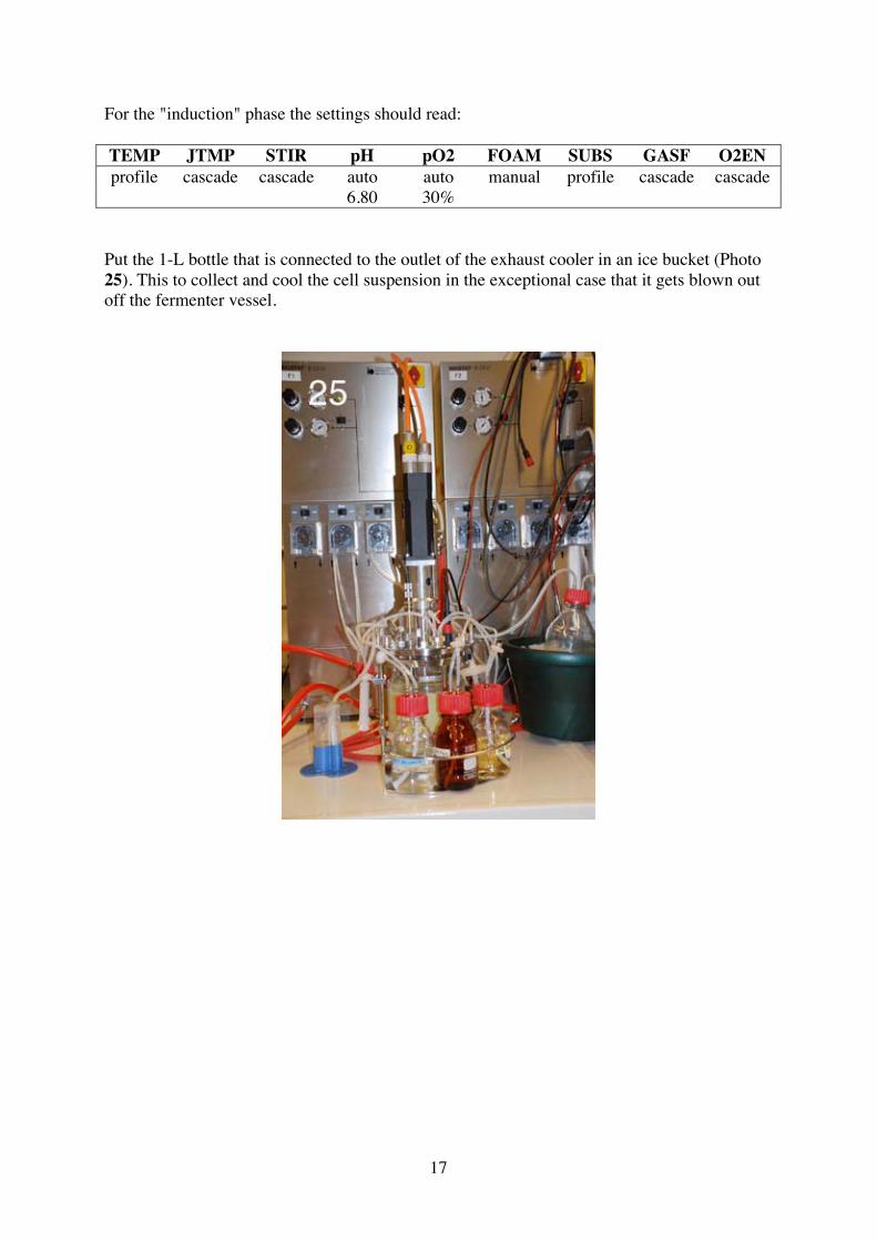
For the "induction" phase the settings should read:
TEMP JTMP STIR pH pO2 FOAM SUBS GASF O2ENprofile cascade cascade auto auto manual profile cascade cascade
6.80 30%
Put the 1-L bottle that is connected to the outlet of the exhaust cooler in an ice bucket (Photo25). This to collect and cool the cell suspension in the exceptional case that it gets blown outoff the fermenter vessel.
18
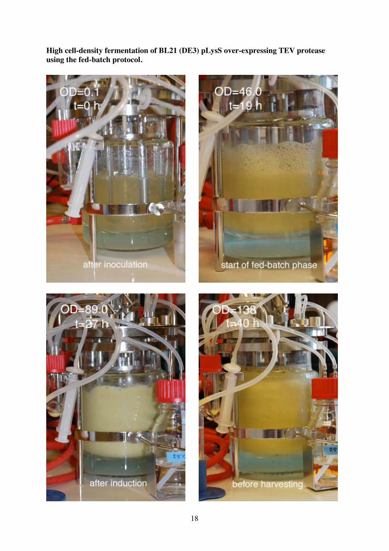
High cell-density fermentation of BL21 (DE3) pLysS over-expressing TEV proteaseusing the fed-batch protocol.

19
Day 4 Harvesting of the cells
16. Harvesting of the cells
The harvesting of the cells is done via the manual sampler using gravity flow. The culturefluid is collected in two 600-ml centrifuge bottles (for the Eppendorf centrifuge). The bottlesare put on ice on a low cupboard (located under the clean bench) and should be in front of thefermenter vessel. It is important that the bottles are placed below the fermenter vessel, so thatthe gravity flow continues running once it has been established.
1. Switch off the "Base" and "Substrate" pumps.2. Select the fermenter unit of which you want to harvest the culture on the main screen.3. Press "Controller". Switch off all the controllers except "STIR" and "GASF". Start
with the "pO2" controller.
The settings should read:
TEMP JTMP STIR pH pO2 FOAM SUBS GASF O2ENoff off auto off off off off auto off
4. Attach a short extension on the outlet tubing of the sample vessel. It should be longenough for the tubing to reach the centrifuge bottles. Place the end of the tubing inone of the centrifuge bottles.
5. Remove the clamp on the tubing between the fermenter vessel and the sample vessel.6. Fill the sample bottle with culture fluid using the syringe.7. Release the clamp on the outlet tubing and let the culture liquid flow freely. Cover the
bottle with a piece of alufoil to prevent the formation of aerosols.8. Fill the first centrifuge bottle with approx. 400 ml culture liquid.9. Put the clamp on the outlet tubing back in place and move the tubing to the second
centrifuge bottle.10. Press "STIR" and switch off of the stirrer (alternatively use the controller).11. Release the clamp on the outlet tubing and fill the second centrifuge bottle. To allow
most of the culture liquid the flow out it is important to tilt the vessel at the side of thesampling tube.
12. Once the liquid has reached the bottom of the sampling tube the gravity flow stops.Put the vessel back on its feet. Open the sample port and remove the remainingculture liquid using a plastic pipette.
13. Fill the fermenter vessel with 1 L Milli-Q water.14. Press "GASF" and switch of the aeration (alternatively use the Controller).15. Aliquot out the cell suspension into 50-ml Falcon tubes, close them and spin them for
45 min at 4600 rpm to pellet the cells.At the end of a fermentation the culture liquid will be approx. 850 ml. This volumecan be conveniently spun in two rounds using ten 50-ml Falcon tubes.
20
17. Cleaning of the feed tubing
Before re-autoclaving the fermenter, the feed tubing need to be emptied and extensivelyrinsed with water.
1. Remove the tubing and lead again through the pumps in an anti-clockwise fashion(from bottle to 4-way sampler).In this way the solution in the tubing should be pumped towards the bottles.
2. Set the pumps to "man" and wait until the tubing is empty.It is impossible to remove all of the antifoam from the tubing. Try to remove as muchas you can.
3. Remove the antifoam tubing from the pump and clamp it for autoclaving (protocol18).
4. Replace the "ammonia" and "glucose feed" bottles with empty 250-ml bottles.The ammonia bottle is refilled and will be used again in the next fermentation.
5. Rinse the tubing with at least 100 ml Milli-Q water.6. Take the tubing out of the beaker with water and continue pumping until the tubing is
dry.7. Remove the tubing from the pumps and empty the bottles.
18. Autoclaving the fermenter vessel
Prepare the fermenter vessel for autoclaving as described in protocol 2.1
1. Re-attach the sample port to the fermenter vessel:Replace the white rubber septum into the sample port opening and fix it with themetal ring. Cover the septum with the metal plug.
2. Clamp all the tubing except the outlet of the exhaust cooler prior to autoclaving. Thisincludes:
• aeration tubing (sparger)• feed tubing (3 fold)• manual sampler tubing• manual sampler outlet tubing
3. Replace the protective cap on the pH probe.The probe should never be autoclaved without the protective cap!
4. Place the fermenter vessel in the instrument and autoclave for 20 min at 121°C.
21
Day 5 Cleaning of the autoclaved fermenter
19. Cleaning of the fermenter
After the fermenter has cooled down it can be dismantled step by step for cleaning.
1. Remove the pH and DO probes.
pH probe Unscrew the probe (using spanner no 17), clean carefullywith water and dry with a tissue. Place the probe in about10 ml electrode cleaning solution (Mettler Toledo) in a50-ml Falcon tube and incubate for several hours. Rinse itwith water and dry with a tissue. Replace the cap filledwith 3 M KCl solution.The electrode cleaning solution can be used for severalweeks.
DO probe Unscrew the probe (using spanner no 19), clean carefullywith water and dry with a tissue. Replace the green plasticcap and store in its staropore box.
2. Remove the clamps except the one on the antifoam feeding tubing.The clamps are collected in a blue plastic box on the trolley.
3. Disconnect the tubing from the vessel lid.
Aeration tubing The large filter can be dried in the 37°C incubator andused again during autoclaving.
Outlet tubing Unscrew the lid from the 1-L bottle. Rinse the bottle andwash it in the washing machine. Rinse the tubing with.When necessary clean the ends of the tubing using aconic (pipe) cleaner.Sometimes it's not possible to clean the tubing properly.In that case it will be discarded and replace by newtubing.
Feeding tubing Store the antifoam bottle plus clamped tubing on thetrolley for the next fermentation.Unscrew the lids from the other two bottles. Rinse thebottles and wash them in the washing machine. Rinse thetubing with water and dry with air (using the 50-mlsyringe). When necessary clean the ends of the tubingusing a conic (pipe) cleaner.Sometimes the tubing is blocked because of the clampingduring autoclaving. This problem can be fixed bysqueezing the tubing until it opens.
Sampling tubing Unscrew the sample vessel and clean it with a brush.Rinse the tubing with water. When necessary clean theends of the tubing using a conic (pipe) cleaner.
4. Remove the other parts from the vessel lid.
22
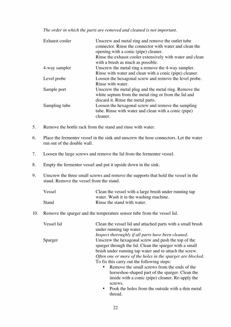
The order in which the parts are removed and cleaned is not important.
Exhaust cooler Unscrew and metal ring and remove the outlet tubeconnector. Rinse the connector with water and clean theopening with a conic (pipe) cleaner.Rinse the exhaust cooler extensively with water and cleanwith a brush as much as possible.
4-way sampler Unscrew the metal ring a remove the 4-way sampler.Rinse with water and clean with a conic (pipe) cleaner.
Level probe Loosen the hexagonal screw and remove the level probe.Rinse with water.
Sample port Unscrew the metal plug and the metal ring. Remove thewhite septum from the metal ring or from the lid anddiscard it. Rinse the metal parts.
Sampling tube Loosen the hexagonal screw and remove the samplingtube. Rinse with water and clean with a conic (pipe)cleaner.
5. Remove the bottle rack from the stand and rinse with water.
6. Place the fermenter vessel in the sink and unscrew the hose connectors. Let the waterrun out of the double wall.
7. Loosen the large screws and remove the lid from the fermenter vessel.
8. Empty the fermenter vessel and put it upside down in the sink.
9. Unscrew the three small screws and remove the supports that hold the vessel in thestand. Remove the vessel from the stand.
Vessel Clean the vessel with a large brush under running tapwater. Wash it in the washing machine.
Stand Rinse the stand with water.
10. Remove the sparger and the temperature sensor tube from the vessel lid.
Vessel lid Clean the vessel lid and attached parts with a small brushunder running tap water.Inspect thoroughly if all parts have been cleaned.
Sparger Unscrew the hexagonal screw and push the top of thesparger through the lid. Clean the sparger with a smallbrush under running tap water and re-attach the screw.Often one or more of the holes in the sparger are blocked.To fix this carry out the following steps:
• Remove the small screws from the ends of thehorseshoe-shaped part of the sparger. Clean theinside with a conic (pipe) cleaner. Re-apply thescrews.
• Pook the holes from the outside with a thin metalthread.

23
Repeat these steps (especially the latter) until all holesare open. This can be checked by running water throughthe sparger. Finally dry the sparger with air (using the 50-ml syringe).
Temperature sensor tube Unscrew the hexagonal screw and push the top of thetemperature sensor tube through the lid. Clean the tubewith a small brush under running tap water and re-attachthe screw.
24
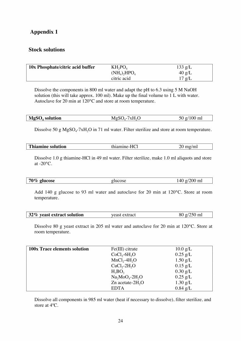
Appendix 1
Stock solutions
10x Phosphate/citric acid buffer KH2PO4 133 g/L(NH4)2HPO4 40 g/Lcitric acid 17 g/L
Dissolve the components in 800 ml water and adapt the pH to 6.3 using 5 M NaOHsolution (this will take approx. 100 ml). Make up the final volume to 1 L with water.Autoclave for 20 min at 120°C and store at room temperature.
MgSO4 solution MgSO4-7xH2O 50 g/100 ml
Dissolve 50 g MgSO4-7xH2O in 71 ml water. Filter sterilize and store at room temperature.
Thiamine solution thiamine-HCl 20 mg/ml
Dissolve 1.0 g thiamine-HCl in 49 ml water. Filter sterilize, make 1.0 ml aliquots and storeat -20°C.
70% glucose glucose 140 g/200 ml
Add 140 g glucose to 93 ml water and autoclave for 20 min at 120°C. Store at roomtemperature.
32% yeast extract solution yeast extract 80 g/250 ml
Dissolve 80 g yeast extract in 205 ml water and autoclave for 20 min at 120°C. Store atroom temperature.
100x Trace elements solution Fe(III) citrate 10.0 g/LCoCl2-6H2O 0.25 g/LMnCl2-4H2O 1.50 g/LCuCl2-2H2O 0.15 g/LH3BO3 0.30 g/LNa2MoO4-2H2O 0.25 g/LZn acetate-2H2O 1.30 g/LEDTA 0.84 g/L
Dissolve all components in 985 ml water (heat if necessary to dissolve), filter sterilize, andstore at 4ºC.
25
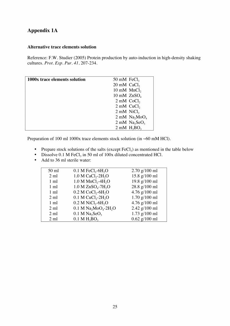
Appendix 1A
Alternative trace elements solution
Reference: F.W. Studier (2005) Protein production by auto-induction in high-density shakingcultures. Prot. Exp. Pur. 41, 207-234.
1000x trace elements solution 50 mM FeCl3
20 mM CaCl2
10 mM MnCl2
10 mM ZnSO4
2 mM CoCl2
2 mM CuCl2
2 mM NiCl2
2 mM Na2MoO4
2 mM Na2SeO3
2 mM H3BO3
Preparation of 100 ml 1000x trace elements stock solution (in ~60 mM HCl).
• Prepare stock solutions of the salts (except FeCl3) as mentioned in the table below• Dissolve 0.1 M FeCl3 in 50 ml of 100x diluted concentrated HCl.• Add to 36 ml sterile water:
50 ml 0.1 M FeCl3-6H2O 2.70 g/100 ml2 ml 1.0 M CaCl2-2H2O 15.8 g/100 ml1 ml 1.0 M MnCl2-4H2O 19.8 g/100 ml1 ml 1.0 M ZnSO4-7H2O 28.8 g/100 ml1 ml 0.2 M CoCl2-6H2O 4.76 g/100 ml2 ml 0.1 M CuCl2-2H2O 1.70 g/100 ml1 ml 0.2 M NiCl2-6H2O 4.76 g/100 ml2 ml 0.1 M Na2MoO4-2H2O 2.42 g/100 ml2 ml 0.1 M Na2SeO3 1.73 g/100 ml2 ml 0.1 M H3BO3 0.62 g/100 ml
26
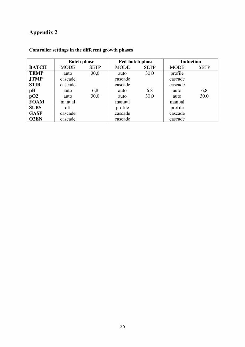
Appendix 2
Controller settings in the different growth phases
Batch phase Fed-batch phase InductionBATCH MODE SETP MODE SETP MODE SETPTEMP auto 30,0 auto 30,0 profileJTMP cascade cascade cascadeSTIR cascade cascade cascadepH auto 6,8 auto 6,8 auto 6,8pO2 auto 30,0 auto 30,0 auto 30,0FOAM manual manual manualSUBS off profile profileGASF cascade cascade cascadeO2EN cascade cascade cascade
27
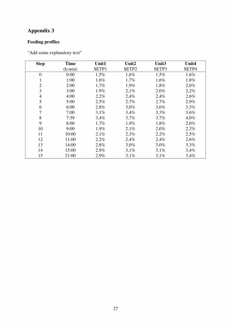
Appendix 3
Feeding profiles
"Add some explanatory text"
Step Time Unit1 Unit2 Unit3 Unit4(h:min) SETP1 SETP2 SETP3 SETP4
0 0:00 1,5% 1,6% 1,5% 1,6%1 1:00 1,6% 1,7% 1,6% 1,8%2 2:00 1,7% 1,9% 1,8% 2,0%3 3:00 1,9% 2,1% 2,0% 2,2%4 4:00 2,2% 2,4% 2,4% 2,6%5 5:00 2,5% 2,7% 2,7% 2,9%6 6:00 2,8% 3,0% 3,0% 3,3%7 7:00 3,1% 3,4% 3,3% 3,6%8 7:59 3,4% 3,7% 3,7% 4,0%9 8:00 1,7% 1,9% 1,8% 2,0%
10 9:00 1,9% 2,1% 2,0% 2,2%11 10:00 2,1% 2,3% 2,2% 2,5%12 11:00 2,2% 2,4% 2,4% 2,6%13 14:00 2,8% 3,0% 3,0% 3,3%14 15:00 2,9% 3,1% 3,1% 3,4%15 21:00 2,9% 3,1% 3,1% 3,4%