high resolution hadron calorimetry option for the sid? adam para alcpg meeting, december 20, 2007
TRANSCRIPT

High Resolution Hadron Calorimetry Option for the
SiD?Adam Para
ALCPG meeting, December 20, 2007

Other Possible Titles
□ Homogeneous Dual Readout Calorimeter□ A List of Miracles and Why You would Like Them
to Happen□ Prospects for Crystal-based Hadron Calorimetry□ Cherenkov-assisted Hadron Calorimetry□ How Good the Hadron Calorimetry Can Be? □ (Some of) Practical Limitations for High Resolution
Hadron Calorimetry.□ ………

Disclaimers/Caveats□ There will nothing particularly new in this
presentation, but rather an attempt to collect various known facts and ideas into a coherent picture
□ The ideas of dual readout hadron calorimetry are very old (~25 years) and the list of people contributing to the conceptual developments is quite long and difficult to reconstruct
□ I am not on this list□ Progress in technology made (perhaps) practical
implementations of some of the possible□ The real goal of this presentation: establish a
possible strategy to develop a dual readout calorimeter design as an option for the SiD LOI. Critical feed-back is of utmost importance

Credits
□ All of the good ideas come from conversations with large number of experts, critics and supporters of the concept of optical readout calorimetry.
□ Mistakes and misunderstandings are all mine□ Simulation results are primarily obtained with ever
improving GEANT4 framework evolving from stand-alone single volume to SLIC-based segmented calorimeter (Hans Wenzel)
□ Analysis of the simulated datasets was carried out by Shin-Shan Yu, Niki Saolidou and George Mavromanolakis)

Hadron Calorimetry for the ILC
□ What is the required energy resolution?□ What drives the requirement?□ What the requirement is really about?
□Stochastic term□Constant term□High energy limit of the resolution□Single particle/jets□Line shape/non-gaussian tails□Jet reconstruction (in the magnetic field):
energy-momentum four-vector. Energy, direction and mass
□ Final judgment involves trade-offs with other aspects of the experiment and opinions may differ

Why is the Hadron Energy Resolution Important?
□ This is a very good question, unfortunately it does not have good answers (IMHO)
□ The best answer so far: W/Z separation:□ Rather esoteric physics motivation□ Lack of quantitave power: DE/E<0.3/√E 0.03,
depending on a day/year or other preferences
□ Honest answers(?): □ Gut feelings?□ Crystal Ball example□ W/Z as a tool for spectroscopy
□ This is a real challenge!!

Jet Measurements: What is Special About the ILC?
□ Jet =□ Collection of particles (operationally)□ Physical manifestation of elementary particles , quarks
and gluons. We really want to measure q/g.□ Intrinsic problems:
□ Arbitrariness of the jet definition (sum of colorless object ≠ colored object)
□ Higher order corrections□ Underlying event
□ W/Z = physical particles. They do correspond to a well defined set of final state particles
□ Lepton collider: clean environment allowing for relatively error-free association of particles to a di-jet system

A Quest for the High Resolution Calorimetry
□ ‘Experimental Physics’ approach: try to construct the best affordable and realistic calorimeter within the constraints of the selected detector concept. It may depend on the concept!

Calorimetry 101 – part I
□ Different types of calorimeters:□ Total absorption: measure a signal proportional to the
total energy deposition. Charge, Scintillation light□ Sampling calorimeter: intersperse the active medium
with the (heavy) absorber. Use the measured signal to ‘represent’ the energy deposited in the absorber (most of the energy to be measured)
□ Homogeneous (the entire volume has the same structure and materials)
□ Inhomogeneous (different materials, sampling frequencies, absorbers, active media)
□ Resolution == fluctuations of the observed signals for the same incoming particle (and its energy)

Calorimetry 101 – Part II: Minimizing the Resolution
□ In a sampling calorimeter the measurable signal fluctuates due to stochastic nature of the energy deposition in the absorber total absorption calorimeters have better resolution
□ An inhomogeneous calorimeter may have different response to different parts of the shower (especially true in the case of the sampling calorimeter) leading to the response fluctuations with the fluctuations of the shower position/development
□ The best resolution can be realized with the homogeneous total absorption calorimeters.
□ Examples: Crystal Ball, KTeV, NA-48, BaBar, CMS
Calorimetry 201
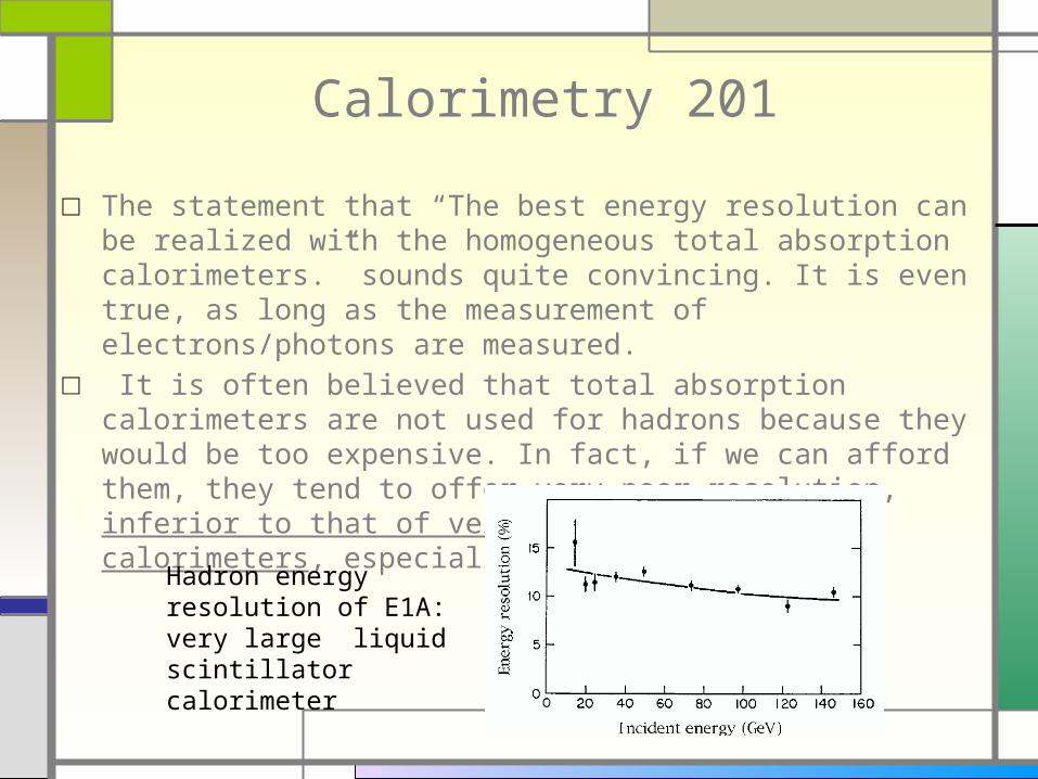
□ The statement that “The best energy resolution can be realized with the homogeneous total absorption calorimeters.” sounds quite convincing. It is even true, as long as the measurement of electrons/photons are measured.
□ It is often believed that total absorption calorimeters are not used for hadrons because they would be too expensive. In fact, if we can afford them, they tend to offer very poor resolution, inferior to that of very coarse sampling calorimeters, especially at high energies.
Hadron energy resolution of E1A: very large liquid scintillator calorimeter

Calorimetry 201 – Part II□ The art of achieving good energy resolution: minimize or eliminate the
largest fluctuations, not just any fluctuations. This requires an understanding of the measurement process and understanding the source of fluctuations. They may depend on factors beyond control, like geometry (leakage).
□ What is the origin of the fluctuations in ‘large enough’ hadron calorimeters? Popular answers:□ Hadron showers fluctuate a lot□ It is because e/h ratio ≠ 1□ It is because e/p ratio ≠ 1□ We do not see/properly measure energy of neutrons □ We do not understand the development of hadronic showers
□ None of these answers is completely wrong, but they describe (some aspects) the problem, rather than explain it
□ Hint: If we were to build a total absorption liquid hydrogen ionization calorimeter (say a huge bubble chamber) it would have excellent energy resolution for hadrons, limited by fluctuation of energy carried out by neutrinos (and muons if it wasn’t ‘big enough’).

Where Does the Energy Go?□ Energy is conserved. How can the observed energy in a total absorption
calorimeter fluctuate?? It surely cannot be bigger than the incoming energy..
□ Hadron-nucleus interaction produce secondary particles:□ EM component (i.e. po)□ ‘hadronic’ component (pions, kaons, fast protons and neutrons)□ ‘nuclear’ component (heavy fragments, spallation neutrons and
protons). Ionization energy deposited by this component is measured, but it may have lower efficiency for conversion into observable signals (Birks). This may contribute to the observed energy deficit.
□ Surprisingly large fraction (20-30%) of the kinetic energy of the incoming hadrons is transformed into potential (hence unobserved) energy of liberated nucleons. This occurs in the primary interactions as well as in the interactions of hadrons produced in the primary and secondary interactions.

Total Absorption Calorimeter: A Primer
□ Electrons/photons interact with atomic electrons. Total energy of the incoming particle is converted into detectable kinetic energy of electrons
□ Hadrons interact with nuclei. They break nuclei and liberate nucleons/nuclear fragments. Even if the kinetic energy of the resulting nucleons is measured, the significant fraction of energy is lost to overcome the binding energy. Fluctuations of the number of broken nuclei dominates fluctuations of the observed energy
□ Excellent energy resolution for electrons/photons□ Relatively poor energy resolution for hadrons (fluctuations constant with
energy, e/p > 1)
Large number of broken nuclei large amount of missing energy
Small number of broken nuclei small amount of missing energy

Total Absorption Calorimeter: A Lesson
□ Kinetic energy deposited in a medium by hadronic showers undergoes large fluctuations
□ Measuring it ‘better’ (for example in a total absorption calorimeter) makes little sense.
□ Unless one supplements the energy measurement with additional information about the number of broken nuclei on the event-by-event basis.
□ The ultimate energy resolution will be limited by the degree of the correlation between the this ‘additional’ information and the actual amount of invisible potential energy.
□ Note: this has little to do with the measurement of the energy carried away by neutrons, which is accounted for in the total observed energy anyway.

Estimating the Number of Broken Nuclei
□ Observation: nuclei are broken by ‘hadronic’ interactions within the shower. Shower = ‘EM’ component + hadronic component, hence a number of hadronic interactions must be anti-correlated with the fraction of energy carried by po’s.
□ EM showers consists of relativistic electrons (m≈0), whereas a significant fraction of particles of the hadronic component are non-relativistic (m>140 MeV) use Cherenkov/scintillation ratio to estimate the number of broken nuclei (P. Mockett 1984)
□ Or use scintillation-Cherenkov light correlation to derive the correction for the unobserved energy

Simulation of Total Absorption Calorimeter
□ ‘Infinite’ uniform block of lead glass (used as a typical material composition and optical properties, like the refraction index n)
□ Stand-alone GEANT4 (Hans Wenzel)□ Total ionization energy deposition summed up for all shower
particles□ Total Cherenkov photons energy summed up for all shower
particles□ Ignored:
□ scintillation mechanism, saturation, light propagation and correction
□ Cherenkov light absorption collection□ Photodetectors

Ionization – Cherenkov (anti)Correlation
□ Example: 10 GeV pion showers in a very large block of a lead glass□ Let S = a*Ionization energy (assume that the scintillation is
proportional to the total ionization energy deposition), a determined from electrons by requiring S = 10 GeV
□ Let C = b*Cherenkov energy (b calibrated with electrons requiring C = 10 GeV)
□ Dimensionless plot: fraction of missing energy as a function of C/S ratio
□ Very little energy-dependentS/E
1-C/S
Width of the total deposited energy (energy resolution of a total absorption calorimeter)
Energy resolution after C/S correction

Cherenkov/Scintillation Based Correction
□ Determine the Corr(C/S) by fitting the ‘experimental’ correlation.
□ Ecorr = S/Corr(C/S)
□ Correction includes all contributions to missing energy (including Birks-like effects)
□ Correction includes contribution of hadrons to Cherenkov light□ Correction function determined from the experiment: simulation
independent (eventually)
C≈S, Scintillation energy close to the particle energy
C<S: scintillation energy an underestimate of the particle energy

Cherenkov-assisted Calorimetry at Work: Single Particle Response
□ Use the ECherenkov/Eionization ratio to ‘correct’ the energy measurement
• Corrected pion shower energy = pion energy (“e/p”=1)
• Linearity of response with the particle energy
• Gaussian response function (better than the uncorrected response)
• Correction function (almost) independent of the actual shower energy
Ecorr/Ebeam

Cherenkov-assisted Calorimetry at Work: Single Particle Energy
Resolution□ Use the ECherenkov/Eionization ratio to ‘correct’ the energy
measurement□ Use RMS of the corrected energy distribution (complete
sample) as a measure of the resolution
• Single charged hadron energy resolution DE/E=0.25/√E
• Scales with energy like 1/√E (no ‘constant term’), in contrast with the resolution of the uncorrected total absorption calorimeter
• Resolution independent of the energy at which the correction is determined
Three curves corresponding to three ‘different’ corrections

From Single Particles to Jets
□ For now: Jet == a collection of particles with varying composition (particles type and spectrum)
□ An experimental challenge (traditional calorimetry): □ Measured jet energy and the resolution depends on the
fragmentation function (fraction of po’s and the spectrum/multiplicity of jet particles, dN/dz)
□ Jet simulation: collection of single particles:□ ‘high’ case : all particles 20 GeV□ ‘basic’ case: 52% of 1 GeV, 21% of 5 GeV, 17% of 10 GeV, 10%
of 20 GeV particles□ ‘low’ case: all particles 5 GeV□ Average fraction of po’s = 0, 20% (with fluctuations)
□ Global correction for the entire jet, based on summed ionization/Cherenkov energies of all particles
□ Correction function derived for 10 GeV single particles used for the whole jet

Jet Energy Resolution: Fragmentation (In)Dependence
• Resolution of Cherenkov-corrected energy measurement is nearly independent of the jet fragmentation
• Resolution (and the response) of the uncorrected energy measurement dependent on the jet fragmentation
0.25 jetEE E

Jet Energy Resolution: Contribution of the Fluctuating EM Component
Fluctuations of the electromagnetic component of the jet:
Dominate (double!) the jet energy resolution in the uncorrected case
• Do not contribute to the jet energy resolution for Cherenkov-corrected measurement
• In fact the presence of the EM jet component slightly improves the jet energy resolution

Summary of the Simulation Studies
□ It appears that the Cherenkov-derived correction to the observed scintillation signal is very robust and very powerful, even with very simple correction/analysis procedure
□ It appears that linear response, with the gaussian lineshape and the energy resolution DE/E<0.25/√E can be achieved for single particles and for collections of particles, independent of the composition oif the collection.
□ The correction principle can be easily understood in terms of relatively elementary physics arguments
□ Perhaps it is even true? Need to check:□ Shower Monte Carlo dependence of the conclusions: Geant 3, Geant 4
with different physics lists, Fluka (studies in progress)□ Dependence on the material composition (sensitivity to the nuclear
effects and their modeling)□ Dependence on the optical properties of the material, refractive index
n, (relative contribution of pions and electrons to the Cherenkov signal)□ Contribution of scintillation/Cherenkov photon statistics□ Efficiency and purity of separation of scintillation and Cherenkov light

Possible Implementations of Dual Readout Calorimetry
□ Dual readout from a single homogeneous total absorption calorimeter (may be subdivided into voxels, if so desired)
□ Planar sampling calorimeter with separate scintillation/Cherenkov readout
□ Sampling calorimeter with scintillating/Cherenkov of fiber readout (DREAM)
□ DREAM-like hadron calorimeter with crystal-like dual readout EM section
□ The homogeneous dual readout option is the simplest conceptually, it is the easiest to understand and it probably offers the best resolution by eliminating the sampling fluctuations and the complications related to the particle and position dependence of the sampling fractions.
Miracle #1
□ Need dense medium which scintillates and is transparent to Cherenkov light. Light properties (wavelength, timing) must such as to allow clean separation of the two light component. Will refer to this medium as ‘crystal’.
□ Crystal must have adequate mechanical properties (Young’s modulus, Poisson ratio), it must be machine-able and easy to use/maintain (not hygroscopic, for example)
□ Must be affordable, when produced in kiloton-scale quantities
□ Must demonstrate experimentally the scintillation/Cherenkov light separation
□ Let’s rename ‘miracle’ to ‘challenge’ and assume that it can be met. Will keep adding requirements to keep it interesting.

Crystal Calorimetry for SiD? Take 1
□ Fill the volume between the tracker and the coil with dual readout crystals. Rin = 1.27 m, Z = 1.8 m
0 0.5 1 1.5 2 2.5 30
50
100
150
200
250
300
350
400
BarrelEndcapTotal cylindrical
Total volume of a calorimeter as a function of its thickness
For a typical thickness of a calorimeter ~1.2 m one needs ~100 m3 of crystals.‘Calibration’ point: CMS ECAL total volume ~ 11 m3.
Crystal Calorimetry for SiD? Take 2
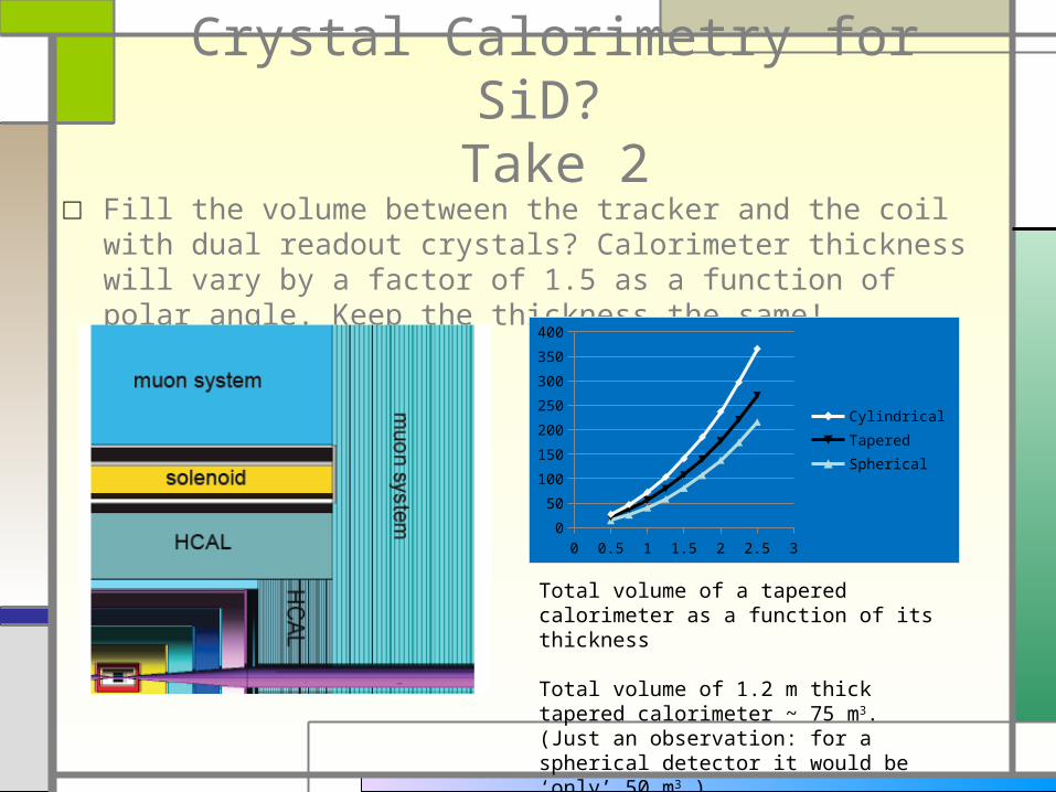
□ Fill the volume between the tracker and the coil with dual readout crystals? Calorimeter thickness will vary by a factor of 1.5 as a function of polar angle. Keep the thickness the same!
0 0.5 1 1.5 2 2.5 30
50
100
150
200
250
300
350
400
CylindricalTaperedSpherical
Total volume of a tapered calorimeter as a function of its thickness
Total volume of 1.2 m thick tapered calorimeter ~ 75 m3.(Just an observation: for a spherical detector it would be ‘only’ 50 m3.)

Pre-Conceptual Design: Calorimeter Segmentation
□ For the energy measurement no segmentation is required. But it is allowed, as long as the separate volumes are properly inter-calibrated to provide the correct sum of the signals.
□ Transverse and longitudinal segmentation will be necessary for a number of reasons:□ Practical (construction, crystal availability and cost)□ Physics requirements: particles (muons?) tracking
through the calorimeter volume, photon identification, photon direction measurement, two/multiparticle spatial resolution
□ Light collection and readout□ The real detector design will require several iterations to
identify and understand all trade-offs involved

Hadron vs EM calorimetry
□ They are traditionally separate/different detectors.□ Differences in their response to hadrons usually precludes very
good hadron energy resolution. This will be of particular concern when very high hadron resolution is to be achieved.
□ Need to meet all the specifications of the ILC EM calorimeter at (the acceptable level) with the crystal calorimetry. Note: single depth EM crystal, CMS-like design, not likely to provide the desired two-particle resolution.
□ Possible solution: □ De-couple energy resolution function from the spatial
measurement□ longitudinal segmentation of the front section of the
calorimeter□ 2-3 layers of silicon pixel detectors (possibly with the pixel size
better than the proposed SiW calorimeters) to provide very detailed spatial information

Miracle #2
□ Separated function EM calorimeter (crystals for the energy measurement) silicon pixels for the spatial measurement provides adequate performance.
□ It ought to be demonstrate-able with the simulation and small test beam module.

SiD Calorimeter Segmentation
□ Version 1.00□ Four layers of 5 x 5 x 5 cm3 crystals with three embedded
silicon pixel layers (a.k.a. EM section): 72,000 crystals□ 8 layers of 10 x 10 x 10 cm3 crystals (a.k.a. hadronic
section): 66,000 crystals□ Reality check, sort of, CMS ECAL 80,000 crystals□ It is important to keep the channel count to a sensible
minimum. Cross-calibration and monitoring will be a primary challenge
□ A relatively small size of the SiD detector is an enabling factor here.
□ Projective or cylindrical geometry? Needs careful optimization of performance vs engineering issues. (Cylindrical geometry avoids any projective cracks!)

Light Collection and Readout
□ The enabling technology: silicon photomultipliers. □ 4(8) photodetectors per crystal. The desired number of
photodetectors depends on trade offs between the light collection efficiency and uniformity, detector reliability and cost
□ No visible dead space. □ Signal routing avoiding projective cracks□ Should not affect the energy resolution □ 500,000(1,000,000) photodetectors□ Note: CMS has 124,000 photodetectors (2 per crystal)
□ Detector design philosophy: build in enough redundancy to avoid/minimize the need for repairs.

Miracle #3
□ Silicon Photomultipliers prove to be viable detectors:□Cost-wise□Performance-wise (dynamic range, analog
performance)□ Possible back-up: Avalanche Photodiodes (a la
CMS)□The challenge of the APD solution:
performance in the middle of the EM shower□ Integrated (single channel?) readout electronics is
developed

High Resolution: Limiting Factors
□ Sobering lessons from high resolution crystal EM calorimeters: the stochastic term is not really important. The real life detector resolution is limited by noise and/or detector non-uniformites (constant term)
□ Encouraging lesson: with enough care and attention the constant term can be kept below 0.4% even for very large systems, like CMS

Crystal Hadron Calorimetry vs EM Crystal Calorimetry
□ It was a major concerted effort to keep the constant term below 0.5% (crystal quality control, light collection, hermetic design, calibration and monitoring)
□ But the goals were very ambitious: target energy resolution well below 1%!□ Why the hadron calorimetry should be significantly easier??:
□ Expectations are much lower. An ultimate resolution of the order of 1% would be terrific
□ Many problems are intrinsically much easier: □ The signals are produced in much more distributed fashion. In the
EM calorimetry case the signal sources are very compact, hence the uniformity is critical.
□ the uniformity requirement ought to be quite relaxed□ The local hermeticity (mechanical tolerances) much relaxed
□ Why hadron calorimetry can be more challenging?□ Overall size a factor 5-10 larged□ Hadronic shower containment/leakage

Containment/Leakage vs Energy Resolution
□ Hadronic showers fluctuate, some fraction of energy escapes detection
□ This escaping fraction fluctuates, thus reducing the energy resolution
□ Good energy resolution requires that the fraction of escaping energy is kept below 2-3%. This, in turns, requires that the total thickness of the calorimeter is of the order of 6 l
Leakage vs Energy Resolution
□ Single particle case is the worst case scenario. Problem is largely reduced in jets, where energy is shared between several particles, hence the individual particles energies are much lower. Needs quantification.
□ Use of tracking information to identify the high energy single particles and detect/correct the leakage a la PFA. Very good energy resolution helps.
□ Tail catcher to detect the leaking energy or to tag the jets with the leakage. Correct or reject?? Probably much to be learned from experience of ZEUS
□ Need ‘thick’ calorimeter. Total thickness is limited by practical considerations. 1.2 m? 1.4 m? 1.5 m? Need to use this volume very efficiently:□ Entire radial space used for the shower detection (keep readout gaps to
a minimum, like 0)□ As high interaction length as possible.: high density, but, if possible, in
a form of lowest possible A materials. (Lattice spacing! r~a3)□ Heavy crystals an attractive solution

PFA: Even Better Calorimeter?
□ In principle, if not for the ‘confusion term’, the combination of tracking information with calorimetry can provide the jet energy resolution better than 0.2/√E.
□ The limiting factor, confusion, is related to the effective (especially transverse) size of the hadron shower
□ Transverse size of the hadron shower strongly depends on the ‘probe’. Hadron showers are very small/collimated if only Cherenkov signal are used
□ It would be very interesting to study the performance of the PFA with dual readout calorimeter.
□ A major milestone with SLIC reached recently (Hans Wenzel):□ Complete simulation of the optical media□ Multiple readouts/collection per active volume. Has a number
of other applications too for various systematic studies (neutrons, differences in particles responses, overlaps, etc..)
□ Standard release

Crystals Engineering: a Succes Story
This is a tip of the iceberg. There are tens of known scintillators:• Fluorides/Chlorides/Bromides/Iodides/Sulfides/Oxides• Cross-luminescent/Self-activated/Activated

CMS Lead Tungstate: a Success Story
Inorganic Scintillators
□ Huge industry driven by medical applications and (to a lesser degree) by HEP. More than 10 vendors producing PbWO4, for example.
□ Rapid progress and development on the recent years (PbWO4 a poster child from our perspective). Several success stories of development of new crystals designed to meet the user requirements:□ Large scintillation light yield□ Fast scintillation (nsec scale)□ Blue-ish□ Radiation hard□ Short radiation length/Moliere radius
□ Dual readout hadron calorimeter needs:□ Transparency for Cherenkov light (good transmission at short
wavelength)□ separation of scintillation and Cherenkov light□ Slow scintillation (500-2000 nsec)□ Not very too much scintillation (not to overwhelm Cherenkov signal)□ Longer wavelength (~500 nm)□ LOW COST

Are There any Off-shelf Crystals Which Can be Used?
□ Not really. This would the a truly remarkable miracle! And a failure to meet the requirements.
□ Are there attractive candidates? Yes. PbWO4? CdWO4? The principal changes required:□ Slow down the scintillation□ Move to longer wavelength (Note: time constant and
wavelength are usually correlated anyway)□ Wishful thinking? Not really. This is a solid science.□ Engineered activation centers/dopants□ Does work in practice?
conduction band
valence band
Egtraps
activationcentres(impurities)
lum
ines
cens
e
quen
chin
g
hole
electron
scintillation(200-600nm)
exci
tati
on
excitonband

Waveshifting of Scintillation
□ Such R&D efforts are, in fact, carried out already in a number of places.
□ Examples of PbWO4 crystals from Shanghai Institute of Ceramics doped with two different dopants (A and B)
S762: PWO(Y)
Z9: PWO(A)
Z20: PWO(B)
PWO Samples from SICEmission Spectra

Another Avenue?
□ Rather than starting from known scintillators and try to extract Cherenkov signal start with a good Cherenkov radiator and dope it with scintillator with desired characteristics.
□ Principal challenge: preserve good transmission at short wavelength
□ Attractive candidates? PbF2?
Scintillation of gadolinium-doped PbF2 (C. Woody)

Path To the ‘Right Crystal’?
□ Do not try out re-invent the wheel□ Do not constrain ourselves to the current shopping list. It was
produced to meet different specifications □ Engage (large) crystal-making industry. Make them understand our
requirements and let them figure out what the best crystals could be
□ Understand implications of various technological constraints and
optimize the detector design accordingly (size? Shape? Uniformity?)
□ Cost likely the primary concernExample:•Ingots are produced as cyliners•Hexagonal cells can improve efficiency of crystal production•Shorter crystals (less taper) can improve efficiency

Can we Afford the Crystal Solution?
□ An excellent question. Can’t answer not knowing the target crystal.
□ Cost of crystal is driven by:□ Cost of (high purity) raw materials (for some crystals, like BGO)□ Energy costs (melting temperature a key characteristics)□ Crucible material wear□ Yield (QC, geometry)
□ Given the required volume (~70 m3) a good target price: <$1/cc□ Note: so far concentrated on single large crystals. From the
calorimetry point of view a transparent (at short wavelength) scintillating material is required:□ Novel materials (crystal fibers? P. Lecoq/CERN)□ Scintillating glasses?
Other Areas Not to be Forgotten
□ Mechanical engineering of a huge collection of crystals (support, stresses, baskets/gluing, geometry, construction,
dead spaces)□ Light collection, uniformity, coupling to photodetecotrs
(huge amount of expertise in BaBar, CMS, KTeV, BESIII) □ Calibration and monitoring□ Large scale production of crystals□ Limiting factors in a large system □ Etc.. Etc…□ Too many interesting issues… too little time (not to mention
money)

Possible Plan for the Near Future
□ Firm up the understanding of physics underlying the dual readout calorimetry. Develop some recommendations regarding the desired granularity, light collection efficiency and uniformity.
□ Understand the performance of PFA with the dual readout calorimetry
□ Pursue the R&D on identification of crystals/glasses which offer the possibility of scintillation/Cherenkov light separation. Demonstrate the separation in a test beam.
□ Construct an EM-size test beam prototype with silicon pixel layers to evaluate the performance of the separated functions (energy – topological information) EM calorimeter
□ (Eventually) construct the full size crystal hadron calorimeter and evaluate the energy resolution of the dual readout technique