how to operate cb close/open mmi structure
TRANSCRIPT
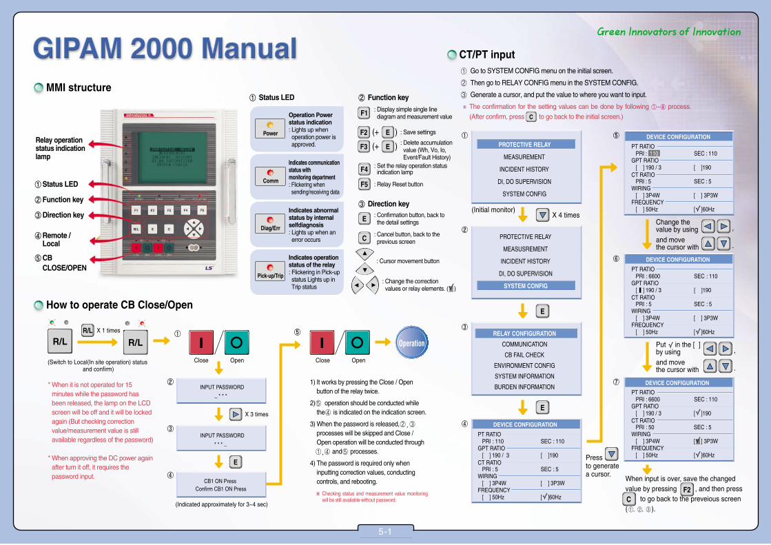
①Status LED
②Function key
Relay operation status indication lamp
③Direction key
④Remote /Local
⑤CBCLOSE/OPEN
MMI structure
How to operate CB Close/Open
① Go to SYSTEM CONFIG menu on the initial screen.
② Then go to RELAY CONFIG menu in the SYSTEM CONFIG.
③ Generate a cursor, and put the value to where you want to input.
※ The confirmation for the setting values can be done by following ①~④ process.
(After confirm, press to go back to the initial screen.)
* When it is not operated for 15minutes while the password hasbeen released, the lamp on the LCDscreen will be off and it will be lockedagain (But checking correctionvalue/measurement value is stillavailable regardless of the password)
* When approving the DC power againafter turn it off, it requires thepassword input.
X 1 times
X 3 times
(Switch to Local(In site operation) status and confirm)
(Indicated approximately for 3~4 sec)
Close Open Close Open
Operation
1) It works by pressing the Close / Openbutton of the relay twice.
2) ⑤ operation should be conducted whilethe ④ is indicated on the indication screen.
3) When the password is released, ② , ③
processes will be skipped and Close /Open operation will be conducted through① , ④ and ⑤ processes.
4) The password is required only wheninputting correction values, conductingcontrols, and rebooting.
※ Checking status and measurement value monitoringwill be still available without password.
② Function key
③ Direction key
① Status LED
Operation Powerstatus indication: Lights up whenoperation power isapproved.
Indicates communicationstatus withmonitoring department: Flickering whensending/receiving data
Indicates abnormalstatus by internalselfdiagnosis: Lights up when anerror occurs
Indicates operationstatus of the relay: Flickering in Pick-upstatus Lights up inTrip status
CT/PT input
When input is over, save the changed value by pressing , and then press to go back to the preveious screen ( ).
(Initial monitor)X 4 times
Press to generate a cursor.
Change the value by usingand movethe cursor with
,
.
Put in the [ ] by usingand movethe cursor with
,
.
5-1
: Display simple single linediagram and measurement value
: Confirmation button, back tothe detail settings
: Cancel button, back to theprevious screen
: Cursor movement button
: Change the correction values or relay elements. ( )
: Set the relay operation statusindication lamp
: Relay Reset button
: Save settings
: Delete accumulationvalue (Wh, Vo, Io,Event/Fault History)

Vector Diagram
To save the changed value, press
When change is completed, press to goback to the previous screen.
X 3 times
Move cursor with
Vector diagram of normal connection
.
Move cursor with
Phase difference between voltages: 120¡Phase difference between currents: 120¡Phase difference between voltage and current: 30¡
The phase sequence must be clockwise for bothvoltage and current
.
Select CB2 by pressing
.
.
.
X 3 times
X 1 times
X 1 times
Save will be completed by pressing
* Each Input/output contact’s names are changeable.(G2K Manager)
* When faulty connection occurs, it must be confirmed as PF (power factor) and Wh(Wattage) can be varied. (But it can be confirmed after the ceiling voltage and current are approved.)
Picturized item of input voltage and phase of current
DI, DO Monitoring CB2 ON/OFF statusindication LEDsetting (When using CB2)
As it is possible to check the current On/Off status of each input/output contact, it is useful for causualanalysis when operating or integration testing the CB.
■ DI MONITORING ■ DO MONITORING
5-2

How to set relay elements
●Setting Items
① INSTANTANEOUS: Indicates instantaneous elements
② Indicates the instantaneous action time, and setting range can beselected up to 30~250ms
③ Indicates the instantaneous current TAP value, and set by samemethod of the ③-1.
③-1 Indicates time delay current TAP value, and means the multiplesof the CT ratio.ex) When the CT ratio 100/5, and the correction value is 0.8In as
in the picture In indicates CT ratio, and 0.8 is the multiple.Therefore, the correction value is...�Based on CT 1st: 0.8 X100 (CT 1st rating) =80A�Based on CT 2nd: 0.8 X5 (CT 2nd rating) =4A
④Time Delay: Indicates the time delay element.
⑤ It is an item to select characteristic curve. In GIPAM, it supportsDefinite-time (DT) and 7 curves of inverse time (SI, VI, EI, LI, KSI,KVI).
⑥This is an item to select the Time Lever. The setting ranges are up to0.05~1.2 and can select in 0.01 units. (Can only be corrected whenselecting inverse time curve at ⑤)
⑦When the definite time curve (DT) is selected at ⑤, Time Levercorrection as shown in the picture above is not possible.
⑧ Indicates the definite time operation time, and the setting range canbe selected up to 0.05~300.00sec.
⑨ This item indicates the Constant Time Delay, and can be selected upto 0.0~10.00sec. (Can only be corrected when selecting the inversetime curve at ⑤)�When selecting the Time Lever, if protection is not possible because
the relay’s operation characteristic curve is on the load characteristiccurve, even though the Lever is selected to its maximum, increasethe relay’s operation characteristic curve to delay the operation timeas much as the changed time in this item.
※For some of delay elements such as OCR and OCGR, can be set bysynthesizing Low and High curves considering the characteristics ofthe loads.
Can select protective relay element by using
.
Put a in [ ] to select the relay, by pressing
.
Use to put a in [ ], to select thefeature you want to use.
When every correction is completed with the same
method, press to save the correction value.
Move cursor with The save will be
completed by pressing
.
.
Go back to the previous screen by pressing
.
Move cursor with
To input correction values for other relay elements, go
through the process.
.
Input the value by using
.
Generate a cursor by pressing
.
Input the value by using
.
5-3

X 2 times
Event number Event content Occurrence timeof the event
It is useful to understand the progress of a Fault before/after the occurrence.
Basic structure
■ Types of EVENT
No. Symbol Content
1 A : Alarm Internal occurrence alarm event
2 R : Relay Relay element operation event
3 S : Status Input/output contact status change event
4 U : User User control event
* Can move to previous or next page, by using .
Event history check - Save 800 items EVENT Interpretation
5-4
■ Basic CODE interpretation
Type of eventA: ALRAM
PU: Pick-UpOP: Operation(operation)
R: R phase operationS: S phase operationT: T phase operation
I: InstantaneousT: Time delay
L: Low curveH: High curve
Type of eventR: Relay operation
Type of eventS: Status (status change)
Type of eventUL: User Local(User control)
Se: Setting, CT Ratio: CT ratioCT ratio change
Changed contact number/nameCB1 ON: CB1 ON output contact (48.33)
ChangedstatusON: OFF ON
Changed mainagentDO: Output contact status
Relay elementoperated(ANSI CODE)
Details(descriptive)
A (Alarm)
- Internal occurrence alarm
R (Relay)
- Relay Pick-Up
element
operation
Operation
S (Status)
- Input/
output DO
contact
status
change
(output DI
contact) (input
contact)
UL CB control
(User Local)
- User R/L change
control
Fault Reset
Relay element
select/delete
Relay element
correction
value
change
Configure
-tion change
Accumulation
value Clear
I-Net
Address
change
Type of EVENT Display Details
GIPAM control power ON (OFF ON
GIPAM internal system error
Relay Pick-up: OCR, instantaneous(I), Low set, R phase operation
Relay Pick-up: OCGR, time delay(T), High set, Io operation
Relay Pick-up: UVR, R, S, T phase operation
Relay Pick-up: OVGR, time delay(T), Low set, Vo operation
Relay Operation: OCR, time delay(T), High set, T phase operation
Relay Operation: POR (open phase) operation
Relay Operation: OVR, time delay(T), Low set, R, S phase operation
Relay Operation: SGR, Vo, Io operation
Output contact status change: CB1 ON output contact ON (OFF ON)
Output contact status change: CB1 ON output contact OFF (ON OFF)
Output contact status change: CB1 OFF output contact ON (OFF ON)
Output contact status change: DO 01 output contact OFF (ON OFF)
Output contact status change: CB1 OFF output and DO
01 output contact ON
status change (OFF ON)
Input contact status change: DI 02 input contact ON (OFF ON)
Input contact status change: DI 01 and DI 11 input contact OFF (ON OFF)
User operates CB 1 ON switch
User operates CB 2 OF switch
User changes it to local status by R/L switch
(Remote Local)
User operates Relay Reset Switch( )
User select whether to use the relay elements,
or delete ( )
User changes the OCR correction value
User changes the UVR correction value
User changes the POR correction value
User changes the NSOVR correction value
User changes the CT ratio
User changes the GPT ratio
User changes the connection type or frequency
User initialize the maximum value of zero-phase sequence voltage
User initialize the valid wattage
User deletes the whole events
User initialize the current demand (Peak value)
User changes the I-Net communication address
CODE : A POWER ON.
CODE : A DIAG ERROR.
CODE : R PU 50/51 I L R
CODE : R PU 50/51N,G T H Io
CODE : R PU 27-1 R S T
CODE : R PU 64 T L Vo
CODE : R OP 50/51 T H T
CODE : R OP 47 (POR)
CODE : R OP 59 T LR S
CODE : R OP 67G Vo Io
CODE : S DO ON CB1 ON
CODE : S DO OF CB1 ON
CODE : S DO ON CB1 OF
CODE : S DO OF 01
CODE : S DO ON CB1 OF, 01
CODE :DI ON 02
CODE :DI OFF 01 11
CODE :U L CB#1 ON
CODE :U L CB#2 OF
CODE :U L Se Remote → Local
CODE :U L Re Fault
CODE :U L Se RY CFG CHANGE
CODE :U L Se 50/51 SET
CODE :U L Se 27-1 SET
CODE :U L Se POR SET
CODE :U L Se 47 SET
CODE :U L Se CT RATIO
CODE :U L Se GPT RATIO
CODE :U L Se WIRING/FREQ
CODE :U L Vo Max
CODE :U L Re Wh
CODE :U L Re EVENT ALL
CODE :U L Re CURRENT Pk DMD
CODE :U L Se INET ADDRESS

Fault display (at relay operation)■ Basic CODE interpretation
* - The fault display on the screen about operated relay elements will disappear by pressing the Reset button ( ).- The information disappeared from the screen will be automatically recorded/saved in the FAULT HISTORY.
* Can move to previous or next page by using .
Operated relayelement(ANSI code)
Incidet value (Can record each phase at the same time)
Inst: instantaneousTime: time delay
Lo: Low curveHi: High curve
R: R phase operation S: S phase operationVo: zerophasesequence voltageoperationlo: Zero phase current operation
X 2 times
X 1 times
FAULT(Fault) number
Fault content Fault value Relayoperation timeSame as the displayed contents on
the screen when fault occurred.
※Basic structure
※The CODE and VALUE in the FAULT HISTORY issame with the content displayed when the faultoccurred, and the TIME (Fault occurrence time) willbe additionally recorded.
5-5
Fault history check - Save 200 items
Fault element Display Details
OCR (instantaneous)
OCR (time delay)
OCGR (instantaneous)
OCGR (time delay)
UVR
OVR
POR
SGR
DGR
NSOVR
(negative
sequence voltage)
NSOCR
(negative sequence
over current)
OCR instantaneous operation (Low set)
Fault cause: R phase over current
Fault value: Ir=34.8A
OCR time delay operation (High set)
Fault cause: R, S phase over current
Fault value: Ir=38.7A, Is=42.3A
OCGR instantaneous operation (High set)
Fault cause: Io (zero phase current)
Fault value: Io=18.2A
OCGR time delay action (Low set)
Fault cause: Io (zero phase current)
Fault value: Io=10.6A
UVR operation
Fault cause: R, S, T phase low voltage
Fault value: Va=OV, Vo=OV, Vc=OV
(※ instantaneous/time delay and Low/High set are not classified)
OVR time delay action (Low set)
Fault cause: R phase over voltage
Fault value: Va=7.3kV
POR time delay action
Fault cause: T phase voltage phase sequence
Fault value: Va=6.6kV, Vb=6.7kV, Vc=0.0V
SGR time delay action
Fault cause: Vo, Io (zero-phase sequence voltage, zero phase current)
Fault value: Vo=52V, Io=0.325A, Ph=43.5°
DGR time delay action
Fault cause: Vo, Io (zero-phase sequence voltage, zero phase current)
Fault value: Vo=43.6V, Io=10.2A, Ph=38.4°
NSOVR time delay action
Fault cause: V2 (negative sequence voltage)
Fault value: V2=6.4kV
NSOCR time delay action
Fault cause: I2 (negative sequence current)
Fault value: I2=45.3A
** Relay Trip***50/51 Inst Lo RIa 34.8A
** Relay Trip***50/51 Time Hi R SIa 38.7A Ib 42.3A
** Relay Trip***50/51N.G Inst Hi IoIo 18.2A
** Relay Trip***50/51N.G Time Lo IoIo 10.6A
** Relay Trip***27-1 Time R S TVa 0.0V Vb 0.0V Vc 0.0V
** Relay Trip***59 Time Lo RVa 7.3kV Vb 6.6kV Vc 6.7kV
** Relay Trip***47(POR) TimeVa 6.6kV Vb 6.7kV Vc 0.0V
** Relay Trip***67G Time Vo IoVo 68V Io 0.325A Ph 43.5。。
** Relay Trip***67N Time Vo IoVo 88.3V Io 10.2A Ph 38.4。。
** Relay Trip***47(NSOVR) Time V2
V2 6.4kV
** Relay Trip***46 Time I2I2 45.3A
LOCKED ROTOR
(Burden)
THR
DFR (87T)
LOCKED ROTOR (Burden) time delay action
Fault cause: burden current
Fault value: Ia =76.8A, Ib=74.2A, Ic=74.2A
THR time delay action
Fault cause: Overheat by over current
Fault value: Ia= 82.6A, Ib=84.3A, Ic=84.2A
87T time delay action (Low set)
Fault cause: Error of transformer 1st, 2nd current
Fault value: Ida 10.2A, Idb 5.8A, Idc 4.5A, Ira 10.2A, Irb 7.9A, Irc 6.3A
※ Ida: R phase differential current, Irc: T phase inhibitory current
Fault element Display Details
** Relay Trip***51LR TimeIa 76.8A Ib 74.2A Ic 74.2A
** Relay Trip***49 TimeIa 82.6A Ib 84.3A Ic 84.2A
** Relay Trip***87T Time Lo R S TIda 10.2A Idb 5.8A Idc 4.5A Ira 10.2A Irb 7.9A Irc 6.3A
To use this product’s features fully and safely, please read user’s manualthoroughly before operating.
Please keep this instruction near from the product.
Safety instructions
■ The ‘Safety instructions’ are for using the product properly and safely,in order to prevent accidents or risks. Please follow the instructions.
■ The instructions are divided into ‘Warning’ and ‘Caution’, and themeanings are as follows.
■ The meaning of the symbols indicated on the product and theinstructions are as follows.
There are possibilities of serious injury or
death when the instructions are breached.
is a symbol warns that there are risks under certain
condition.
is a symbol warns that there are risks of electric shock
under certain condition.
There are possibilities of minor injury or
damage to the product when the instructions
are breached.
Warning
Caution
www.lsis.comⓒ 2014.9 LSIS Co.,Ltd. All rights reserved.
Specifications in this catalog are subject to change without notice due to continuous product development and improvement.
�HEAD OFFICELS-ro 127 (Hogye-dong) dongan-gu Anyang-siGyeonggi-do KoreaTel. (82-2)2034-4887, 4873, 4918, 4148Fax. (82-2)2034-4648
�CHEONG-JU PLANTCheong-Ju Plant #1, Song Jung Dong, Hung Duk Ku,Cheong Ju, 361-720, Korea
2013. 06 GIPAM 2000 Manual (E) 2014. 09/(01) 2014. 09 Printed in Korea STAFF
�LSIS (Middle East) FZE ��Dubai, U.A.E. Address: LOB 19 JAFZA VIEW TOWER Room 205, Jebel Ali Freezone P.O. Box 114216, Dubai, United Arab EmiratesTel: 971-4-886 5360 Fax: 971-4-886-5361 e-mail: [email protected] �Dalian LSIS Co., Ltd. ��Dalian, China
Address: No.15, Liaohexi 3-Road, Economic and Technical Development zone, Dalian 116600, ChinaTel: 86-411-8273-7777 Fax: 86-411-8730-7560 e-mail: [email protected]�LSIS (Wuxi) Co., Ltd. ��Wuxi, China
Address: 102-A , National High & New Tech Industrial Development Area, Wuxi, Jiangsu, 214028, P.R.ChinaTel: 86-510-8534-6666 Fax: 86-510-522-4078 e-mail: [email protected]�LSIS-VINA Co., Ltd. ��Hanoi, Vietnam
Address: Nguyen Khe - Dong Anh - Ha Noi - Viet NamTel: 84-4-882-0222 Fax: 84-4-882-0220 e-mail: [email protected]�LSIS-VINA Co., Ltd. ��Hochiminh , Vietnam
Address: 41 Nguyen Thi Minh Khai Str. Yoco Bldg 4th Floor, Hochiminh City, VietnamTel: 84-8-3822-7941 Fax: 84-8-3822-7942 e-mail: [email protected]�LSIS Shanghai Office ��Shanghai, China
Address: Room 32 floors of the Great Wall Building, No. 3000 North Zhongshan Road, Putuo District, Shanghai, ChinaTel: 86-21-5237-9977 Fax: 89-21-5237-7189 e-mail: [email protected]�LSIS Beijing Office ��Beijing, China
Address: B-Tower 17FL.Beijing Global Trade Center B/D. No.36, BeiSanHuanDong-Lu, DongCheng-District,Beijing 100013, P.R. ChinaTel: 86-10-5825-6025,7 Fax: 86-10-5825-6026 e-mail: [email protected]�LSIS Guangzhou Office ��Guangzhou, China
Address: Room 1403, 14/F, New Poly Tower, No.2 Zhongshan Liu Road, Guangzhou 510180, P.R. ChinaTel: 020-8326-6754 Fax: 020-8326-6287 e-mail: [email protected]�LSIS Chengdu Office ��Chengdu, China
Address: Room 1701 17Floor, huamin hanjun internationnal Building, No1 Fuxing Road Chengdu, 610016, P.R. ChinaTel: 86-28-8670-3201 Fax: 86-28-8670-3203 e-mail: [email protected]�LSIS Qingdao Office ��Qingdao, China
Address: Room 2001,20/F,7B40, Galaxy Building, No.29 Shandong Road, Shinan District, Qingdao 266071, P.R. ChinaTel: 86-532-8501-6058 Fax: 86-532-8501-6057 e-mail: [email protected]�LSIS NETHERLANDS Co.Ltd ��Schiphol-Rijk, Netherlands
Address: 1st. Floor, Tupolevlaan 48, 1119NZ,Schiphol-Rijk, The NetherlandsTel: 31-20-654-1420 Fax: 31-20-654-1429 e-mail: [email protected]�LSIS Gurgaon Office ��Gurgaon ,India
Address: 109 First Floor, Park Central, Sector-30, Gurgaon- 122 002, Haryana, India e-mail: [email protected]
��Global Network