how to use this install guide - amazon...
TRANSCRIPT
NOTICE: Automotive Data Solutions Inc. (ADS) recommends having this installation performed by a certifi ed technician. Logos and trademarks used here in are the properties of their respective owners.
WARNINGPressing the printer icon or “quick printing” this document will print
all of the guides in this compilation.
Open the Bookmarks menu and find your vehicle OR scroll down until you find the install guide for your vehicle.
Print only the pages for your vehicle using the advanced options in the Print menu.
Install your Maestro RR according to the guide for your vehicle.
HOW TO USE THIS INSTALL GUIDE1
2
3
SELECT VEHICLE PRINT PAGES NEEDED

OPTIONAL ACCESSORIESNone
PROGRAMMED FIRMWAREADS-RR(SR)-CHR03X-DS
PRODUCTS REQUIREDiDatalink Maestro RR Radio Replacement InterfaceiDatalink Maestro CH3 Installation Harness
INSTALL GUIDEFIAT 500X
3.0 RA1 2016-2017Retains steeRing wheel contRols, vehicle settings, and moRe!
NOTICE: Automotive Data Solutions Inc. (ADS) recommends having this installation performed by a certified technician. Logos and trademarks used here in are the properties of their respective owners.
ADS-RR(SR)-CHR03X-DS maestro.idatalink.com
Fiat 500X 3.0 Ra1 2016-2017
Automotive Data Solutions Inc. © 2017 2
WELCOME
NEED HELP?
Congratulations on the purchase of your iDatalink Maestro RR Radio replacement solution. You are now a few simple steps away from enjoying your new car radio with enhanced features. Before starting your installation, please ensure that your iDatalink Maestro module is programmed with the correct fi rmware and that you carefully review the Installation Diagram and Vehicle Wire Refer-ence Chart.
Please note that Maestro RR will only retain functionalities that were originally available in the vehicle.
1 866 427-2999
maestro.idatalink.com/supportwww.12voltdata.com/forum
DURING INSTALLATION
Installation Instructions 3
Wiring Diagram 4
Radio Wire Reference Chart 5

ADS-RR(SR)-CHR03X-DS maestro.idatalink.com
Fiat 500X 3.0 Ra1 2016-2017
Automotive Data Solutions Inc. © 2017 3
INSTALLATION INSTRUCTIONS STEP 1
• Unbox the aftermarket radio and locate its main harness.
• Connect the wires shown on the next page from aftermarket radio main harness to the CH3x T-harness and match the wire functions.
STEP 2
• Plug the female WHITE 2 pin connector to the male WHITE connector of your CH3x T-harness.
• Remove the factory radio.
STEP 3• Connect the factory harness to the CH3x T-harness.
STEP 4• Plug the male BLACK 2 pin connector of your CH3x
T-harness into the OBDII harness.
• Plug the OBDII connector into the OBDII of the vehicle.
STEP 5• Plug the aftermarket radio harnesses into the aftermarket
radio.
• Plug the Data cable to the data port of the aftermarket radio.
• Insert the Audio cable into the iDatalink 3.5 mm audio jack of the aftermarket radio.
STEP 6• Connect all the harnesses to the Maestro RR module then
test your installation.
TROUBLESHOOTING TIPS:
• To reset the module back its factory settings, turn the key to the OFF position then disconnect all connectors from the module. Press and hold the module’s programming button and connect all the connectors back to the module. Wait, the module’s LED will fl ash RED rapidly (this may take up to 10 seconds). Release the programming button. Wait, the LED will turn solid GREEN for 2 seconds.
• For technical assistance call 1-866-427-2999 or e-mail “[email protected]”. Visit us at “maestro.idatalink.com/support” and “www.12voltdata.com/forum/”
1

ADS-RR(SR)-CHR03X-DS maestro.idatalink.com
Fiat 500X 3.0 Ra1 2016-2017
Automotive Data Solutions Inc. © 2017 4
C
A
H
FG
D
C
A
G
F
H
1
D
BACKUP CAMBACKUP CAM
WIRING DIAGRAMSTEP 1
STEP 2 STEP 3
STEP 5
STEP 6
MAESTRO RR MODULE
WHITE - LF SPEAKER (+)WHITE/BLACK - LF SPEAKER (-)GRAY - RF SPEAKER (+)GRAY/BLACK - RF SPEAKER (-)GREEN - LR SPEAKER (+)GREEN/BLACK - LR SPEAKER (-)
PURPLE/BLACK - RR SPEAKER (-)
YELLOW - 12V (+)
BLACK - GROUNDRED - ACCESSORY (+)
ORANGE - ILLUMINATION (+)PURPLE/WHITE - REVERSE LIGHT (+)LTGREEN - E-BRAKE (-)
BLUE/WHITE - AMP. TURN ON (+)
MAINHARNESS
DATACABLE
AUDIOCABLE
PURPLE - RR SPEAKER (+)
CONNECT TOAFTERMARKET RADIO
CH3 X T-HARNESS
FACTORY RADIOHARNESS WIRES FROM
VEHICLE
PINK - VEHICLE SPEED (CONNECT IF THERE IS A MATCH)YELLOW/BLACK - FOOT BRAKE (CONNECT IF THERE IS A MATCH)
GREEN GREEN
WHITE
WHITE
WHITE
N.C.
RCA CABLESBROWN (NOT CONNECTED)
READ NOTE ININSTALLATIONINSTRUCTIONS
SECTION
STEP 4 OBDII CONNECTOR
WHITE
ADS-RR(SR)-CHR03X-DS maestro.idatalink.com
Fiat 500X 3.0 Ra1 2016-2017
Automotive Data Solutions Inc. © 2017 5
RADIO WIRE REFERENCE CHART
WireDescription Polarity Wire Color on Maestro
T-Harness Wire Color on Alpine cable Wire Color on Kenwood cable Wire Color on Pioneer cable
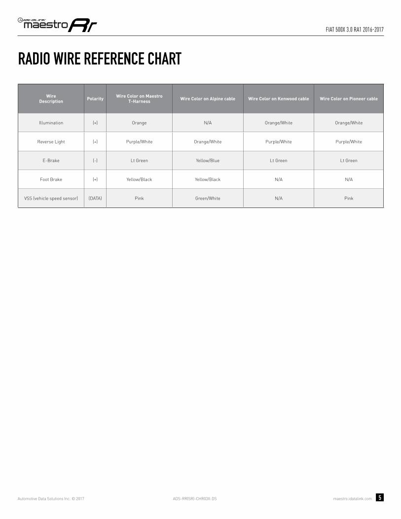
Illumination (+) Orange N/A Orange/White Orange/White
Reverse Light (+) Purple/White Orange/White Purple/White Purple/White
E-Brake (-) Lt Green Yellow/Blue Lt Green Lt Green
Foot Brake (+) Yellow/Black Yellow/Black N/A N/A
VSS (vehicle speed sensor) (DATA) Pink Green/White N/A Pink

OPTIONAL ACCESSORIESNone
PROGRAMMED FIRMWAREADS-RR(SR)-CHR03X-DS
PRODUCTS REQUIREDiDatalink Maestro RR Radio Replacement InterfaceiDatalink Maestro CH3 Installation Harness
INSTALL GUIDEFIAT 500X
5.0 RA2 & 6.5 RA4 2016-2017Retains steeRing wheel contRols, vehicle settings, and moRe!
NOTICE: Automotive Data Solutions Inc. (ADS) recommends having this installation performed by a certified technician. Logos and trademarks used here in are the properties of their respective owners.

ADS-RR(SR)-CHR03X-DS maestro.idatalink.com
Fiat 500X 5.0 Ra2 & 6.5 Ra4 2016-2017
Automotive Data Solutions Inc. © 2017 2
WELCOME
NEED HELP?
Congratulations on the purchase of your iDatalink Maestro RR Radio replacement solution. You are now a few simple steps away from enjoying your new car radio with enhanced features. Before starting your installation, please ensure that your iDatalink Maestro module is programmed with the correct fi rmware and that you carefully review the Installation Diagram and Vehicle Wire Refer-ence Chart.
Please note that Maestro RR will only retain functionalities that were originally available in the vehicle.
1 866 427-2999
maestro.idatalink.com/supportwww.12voltdata.com/forum
DURING INSTALLATION
Installation Instructions 3
Wiring Diagram 4
Radio Wire Reference Chart 5

ADS-RR(SR)-CHR03X-DS maestro.idatalink.com
Fiat 500X 5.0 Ra2 & 6.5 Ra4 2016-2017
Automotive Data Solutions Inc. © 2017 3
INSTALLATION INSTRUCTIONS STEP 1
• Unbox the aftermarket radio and locate its main harness.
• Connect the wires shown on the next page from aftermarket radio main harness to the CH3x T-harness and match the wire functions.
STEP 2
• Plug the female WHITE 2 pin connector to the male WHITE connector of your CH3x T-harness.
• Plug the female BLACK 2 pin connector to the male BLACK connector of your CH3x T-harness.
• Remove the factory radio.
STEP 3• Connect the factory harness to the CH3x T-harness.
STEP 4• Plug the aftermarket radio harnesses into the aftermarket
radio.
• Plug the Data cable to the data port of the aftermarket radio.
• Insert the Audio cable into the iDatalink 3.5 mm audio jack of the aftermarket radio.
STEP 5• Connect all the harnesses to the Maestro RR module then
test your installation.
TROUBLESHOOTING TIPS:
• To reset the module back its factory settings, turn the key to the OFF position then disconnect all connectors from the module. Press and hold the module’s programming button and connect all the connectors back to the module. Wait, the module’s LED will fl ash RED rapidly (this may take up to 10 seconds). Release the programming button. Wait, the LED will turn solid GREEN for 2 seconds.
• For technical assistance call 1-866-427-2999 or e-mail “[email protected]”. Visit us at “maestro.idatalink.com/support” and “www.12voltdata.com/forum/”
1

ADS-RR(SR)-CHR03X-DS maestro.idatalink.com
Fiat 500X 5.0 Ra2 & 6.5 Ra4 2016-2017
Automotive Data Solutions Inc. © 2017 4
C
A
H
FG
D
C
A
G
F
H
2
D
BACKUP CAMBACKUP CAM
CONNECTION NOT REQUIRED
WIRING DIAGRAMSTEP 1
STEP 2 STEP 3
STEP 4
STEP 5
MAESTRO RR MODULE
WHITE - LF SPEAKER (+)WHITE/BLACK - LF SPEAKER (-)GRAY - RF SPEAKER (+)GRAY/BLACK - RF SPEAKER (-)GREEN - LR SPEAKER (+)GREEN/BLACK - LR SPEAKER (-)
PURPLE/BLACK - RR SPEAKER (-)
YELLOW - 12V (+)
BLACK - GROUNDRED - ACCESSORY (+)
ORANGE - ILLUMINATION (+)PURPLE/WHITE - REVERSE LIGHT (+)LTGREEN - E-BRAKE (-)
BLUE/WHITE - AMP. TURN ON (+)
MAINHARNESS
DATACABLE
AUDIOCABLE
PURPLE - RR SPEAKER (+)
CONNECT TOAFTERMARKET RADIO
CH3X T-HARNESS
FACTORY RADIOHARNESS WIRES FROM
VEHICLE
PINK - VEHICLE SPEED (CONNECT IF THERE IS A MATCH)YELLOW/BLACK - FOOT BRAKE (CONNECT IF THERE IS A MATCH)
GREEN GREEN
WHITE
WHITE
WHITE
N.C.
RCA CABLESBROWN (NOT CONNECTED)
READ NOTE ININSTALLATIONINSTRUCTIONS
SECTION
WHITE
BLACKBLACK
ADS-RR(SR)-CHR03X-DS maestro.idatalink.com
Fiat 500X 5.0 Ra2 & 6.5 Ra4 2016-2017
Automotive Data Solutions Inc. © 2017 5
RADIO WIRE REFERENCE CHART
WireDescription Polarity Wire Color on Maestro
T-Harness Wire Color on Alpine cable Wire Color on Kenwood cable Wire Color on Pioneer cable
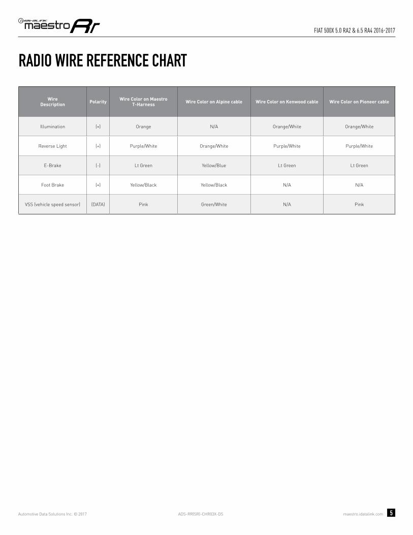
Illumination (+) Orange N/A Orange/White Orange/White
Reverse Light (+) Purple/White Orange/White Purple/White Purple/White
E-Brake (-) Lt Green Yellow/Blue Lt Green Lt Green
Foot Brake (+) Yellow/Black Yellow/Black N/A N/A
VSS (vehicle speed sensor) (DATA) Pink Green/White N/A Pink

OPTIONAL ACCESSORIESNone
PROGRAMMED FIRMWAREADS-RR(SR)-CHR03X-DS
PRODUCTS REQUIREDiDatalink Maestro RR Radio Replacement InterfaceiDatalink Maestro CH3 Installation Harness
INSTALL GUIDEJEEP RENEGADE
3.0 RA1 2015-2017Retains steeRing wheel contRols, vehicle settings, and moRe!
NOTICE: Automotive Data Solutions Inc. (ADS) recommends having this installation performed by a certified technician. Logos and trademarks used here in are the properties of their respective owners.
ADS-RR(SR)-CHR03X-DS maestro.idatalink.com
Jeep Renegade 3.0 Ra1 2015-2017
Automotive Data Solutions Inc. © 2017 2
WELCOME
NEED HELP?
Congratulations on the purchase of your iDatalink Maestro RR Radio replacement solution. You are now a few simple steps away from enjoying your new car radio with enhanced features. Before starting your installation, please ensure that your iDatalink Maestro module is programmed with the correct fi rmware and that you carefully review the Installation Diagram and Vehicle Wire Refer-ence Chart.
Please note that Maestro RR will only retain functionalities that were originally available in the vehicle.
1 866 427-2999
maestro.idatalink.com/supportwww.12voltdata.com/forum
DURING INSTALLATION
Installation Instructions 3
Wiring Diagram 4
Radio Wire Reference Chart 5
ADS-RR(SR)-CHR03X-DS maestro.idatalink.com
Jeep Renegade 3.0 Ra1 2015-2017
Automotive Data Solutions Inc. © 2017 3
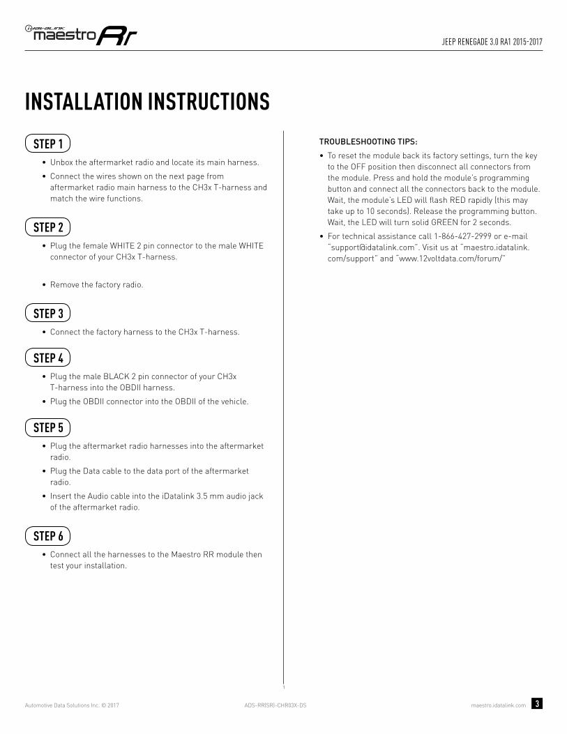
INSTALLATION INSTRUCTIONS STEP 1
• Unbox the aftermarket radio and locate its main harness.
• Connect the wires shown on the next page from aftermarket radio main harness to the CH3x T-harness and match the wire functions.
STEP 2
• Plug the female WHITE 2 pin connector to the male WHITE connector of your CH3x T-harness.
• Remove the factory radio.
STEP 3• Connect the factory harness to the CH3x T-harness.
STEP 4• Plug the male BLACK 2 pin connector of your CH3x
T-harness into the OBDII harness.
• Plug the OBDII connector into the OBDII of the vehicle.
STEP 5• Plug the aftermarket radio harnesses into the aftermarket
radio.
• Plug the Data cable to the data port of the aftermarket radio.
• Insert the Audio cable into the iDatalink 3.5 mm audio jack of the aftermarket radio.
STEP 6• Connect all the harnesses to the Maestro RR module then
test your installation.
TROUBLESHOOTING TIPS:
• To reset the module back its factory settings, turn the key to the OFF position then disconnect all connectors from the module. Press and hold the module’s programming button and connect all the connectors back to the module. Wait, the module’s LED will fl ash RED rapidly (this may take up to 10 seconds). Release the programming button. Wait, the LED will turn solid GREEN for 2 seconds.
• For technical assistance call 1-866-427-2999 or e-mail “[email protected]”. Visit us at “maestro.idatalink.com/support” and “www.12voltdata.com/forum/”
1
ADS-RR(SR)-CHR03X-DS maestro.idatalink.com
Jeep Renegade 3.0 Ra1 2015-2017
Automotive Data Solutions Inc. © 2017 4
C
A
H
FG
D
C
A
G
F
H
1
D
BACKUP CAMBACKUP CAM
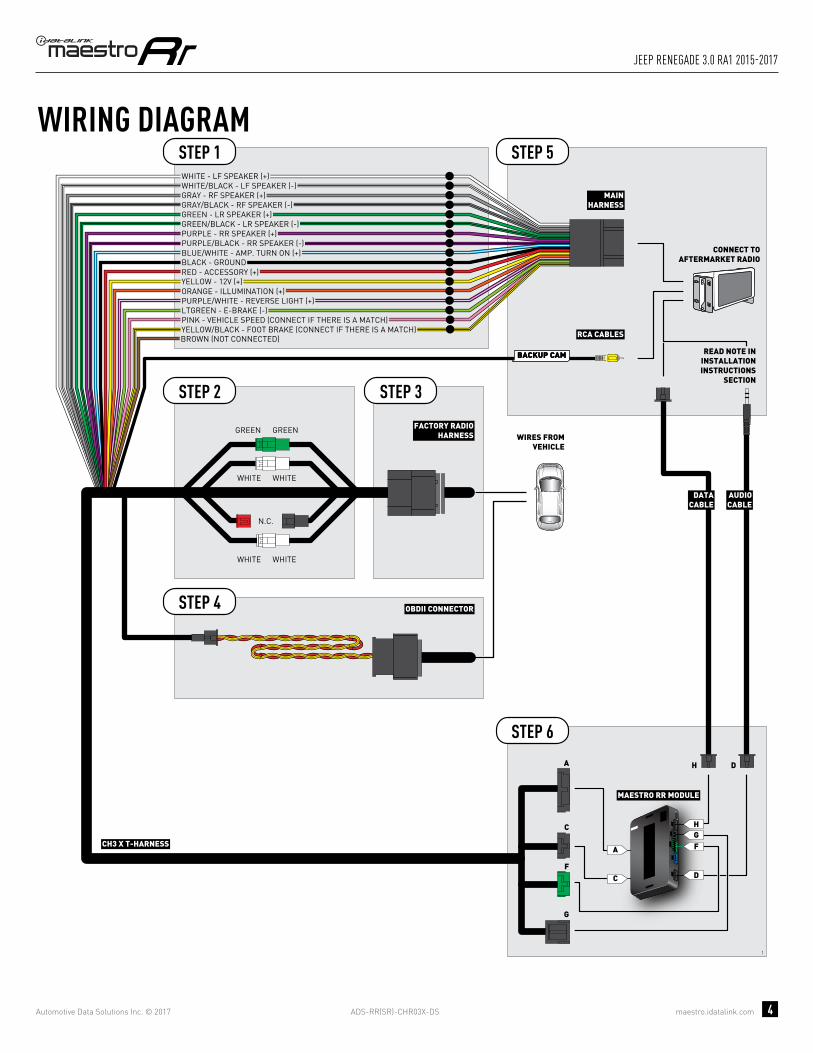
WIRING DIAGRAMSTEP 1
STEP 2 STEP 3
STEP 5
STEP 6
MAESTRO RR MODULE
WHITE - LF SPEAKER (+)WHITE/BLACK - LF SPEAKER (-)GRAY - RF SPEAKER (+)GRAY/BLACK - RF SPEAKER (-)GREEN - LR SPEAKER (+)GREEN/BLACK - LR SPEAKER (-)
PURPLE/BLACK - RR SPEAKER (-)
YELLOW - 12V (+)
BLACK - GROUNDRED - ACCESSORY (+)
ORANGE - ILLUMINATION (+)PURPLE/WHITE - REVERSE LIGHT (+)LTGREEN - E-BRAKE (-)
BLUE/WHITE - AMP. TURN ON (+)
MAINHARNESS
DATACABLE
AUDIOCABLE
PURPLE - RR SPEAKER (+)
CONNECT TOAFTERMARKET RADIO
CH3 X T-HARNESS
FACTORY RADIOHARNESS WIRES FROM
VEHICLE
PINK - VEHICLE SPEED (CONNECT IF THERE IS A MATCH)YELLOW/BLACK - FOOT BRAKE (CONNECT IF THERE IS A MATCH)
GREEN GREEN
WHITE
WHITE
WHITE
N.C.
RCA CABLESBROWN (NOT CONNECTED)
READ NOTE ININSTALLATIONINSTRUCTIONS
SECTION
STEP 4 OBDII CONNECTOR
WHITE
ADS-RR(SR)-CHR03X-DS maestro.idatalink.com
Jeep Renegade 3.0 Ra1 2015-2017
Automotive Data Solutions Inc. © 2017 5
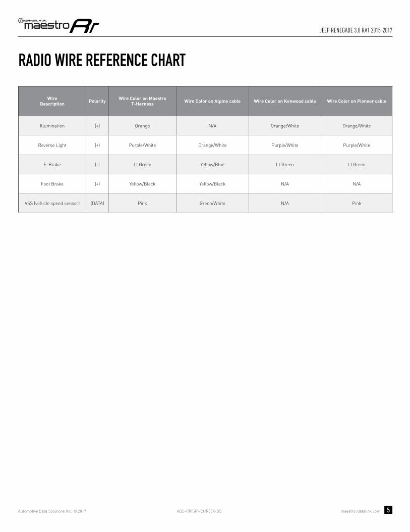
RADIO WIRE REFERENCE CHART
WireDescription Polarity Wire Color on Maestro
T-Harness Wire Color on Alpine cable Wire Color on Kenwood cable Wire Color on Pioneer cable
Illumination (+) Orange N/A Orange/White Orange/White
Reverse Light (+) Purple/White Orange/White Purple/White Purple/White
E-Brake (-) Lt Green Yellow/Blue Lt Green Lt Green
Foot Brake (+) Yellow/Black Yellow/Black N/A N/A
VSS (vehicle speed sensor) (DATA) Pink Green/White N/A Pink

OPTIONAL ACCESSORIESNone
PROGRAMMED FIRMWAREADS-RR(SR)-CHR03X-DS
PRODUCTS REQUIREDiDatalink Maestro RR Radio Replacement InterfaceiDatalink Maestro CH3 Installation Harness
INSTALL GUIDEJEEP RENEGADE
5.0 RA2 & 6.5 RA4 2015-2017Retains steeRing wheel contRols, vehicle settings, and moRe!
NOTICE: Automotive Data Solutions Inc. (ADS) recommends having this installation performed by a certified technician. Logos and trademarks used here in are the properties of their respective owners.
ADS-RR(SR)-CHR03X-DS maestro.idatalink.com
Jeep Renegade 5.0 Ra2 & 6.5 Ra4 2015-2017
Automotive Data Solutions Inc. © 2017 2
WELCOME
NEED HELP?
Congratulations on the purchase of your iDatalink Maestro RR Radio replacement solution. You are now a few simple steps away from enjoying your new car radio with enhanced features. Before starting your installation, please ensure that your iDatalink Maestro module is programmed with the correct fi rmware and that you carefully review the Installation Diagram and Vehicle Wire Refer-ence Chart.
Please note that Maestro RR will only retain functionalities that were originally available in the vehicle.
1 866 427-2999
maestro.idatalink.com/supportwww.12voltdata.com/forum
DURING INSTALLATION
Installation Instructions 3
Wiring Diagram 4
Radio Wire Reference Chart 5
ADS-RR(SR)-CHR03X-DS maestro.idatalink.com
Jeep Renegade 5.0 Ra2 & 6.5 Ra4 2015-2017
Automotive Data Solutions Inc. © 2017 3
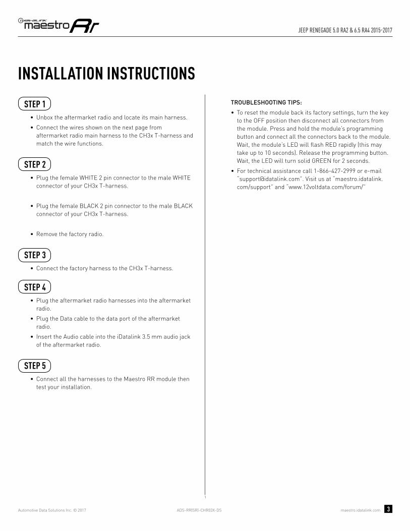
INSTALLATION INSTRUCTIONS STEP 1
• Unbox the aftermarket radio and locate its main harness.
• Connect the wires shown on the next page from aftermarket radio main harness to the CH3x T-harness and match the wire functions.
STEP 2
• Plug the female WHITE 2 pin connector to the male WHITE connector of your CH3x T-harness.
• Plug the female BLACK 2 pin connector to the male BLACK connector of your CH3x T-harness.
• Remove the factory radio.
STEP 3• Connect the factory harness to the CH3x T-harness.
STEP 4• Plug the aftermarket radio harnesses into the aftermarket
radio.
• Plug the Data cable to the data port of the aftermarket radio.
• Insert the Audio cable into the iDatalink 3.5 mm audio jack of the aftermarket radio.
STEP 5• Connect all the harnesses to the Maestro RR module then
test your installation.
TROUBLESHOOTING TIPS:
• To reset the module back its factory settings, turn the key to the OFF position then disconnect all connectors from the module. Press and hold the module’s programming button and connect all the connectors back to the module. Wait, the module’s LED will fl ash RED rapidly (this may take up to 10 seconds). Release the programming button. Wait, the LED will turn solid GREEN for 2 seconds.
• For technical assistance call 1-866-427-2999 or e-mail “[email protected]”. Visit us at “maestro.idatalink.com/support” and “www.12voltdata.com/forum/”
1

ADS-RR(SR)-CHR03X-DS maestro.idatalink.com
Jeep Renegade 5.0 Ra2 & 6.5 Ra4 2015-2017
Automotive Data Solutions Inc. © 2017 4
C
A
H
FG
D
C
A
G
F
H
2
D
BACKUP CAMBACKUP CAM
CONNECTION NOT REQUIRED
WIRING DIAGRAMSTEP 1
STEP 2 STEP 3
STEP 4
STEP 5
MAESTRO RR MODULE
WHITE - LF SPEAKER (+)WHITE/BLACK - LF SPEAKER (-)GRAY - RF SPEAKER (+)GRAY/BLACK - RF SPEAKER (-)GREEN - LR SPEAKER (+)GREEN/BLACK - LR SPEAKER (-)
PURPLE/BLACK - RR SPEAKER (-)
YELLOW - 12V (+)
BLACK - GROUNDRED - ACCESSORY (+)
ORANGE - ILLUMINATION (+)PURPLE/WHITE - REVERSE LIGHT (+)LTGREEN - E-BRAKE (-)
BLUE/WHITE - AMP. TURN ON (+)
MAINHARNESS
DATACABLE
AUDIOCABLE
PURPLE - RR SPEAKER (+)
CONNECT TOAFTERMARKET RADIO
CH3X T-HARNESS
FACTORY RADIOHARNESS WIRES FROM
VEHICLE
PINK - VEHICLE SPEED (CONNECT IF THERE IS A MATCH)YELLOW/BLACK - FOOT BRAKE (CONNECT IF THERE IS A MATCH)
GREEN GREEN
WHITE
WHITE
WHITE
N.C.
RCA CABLESBROWN (NOT CONNECTED)
READ NOTE ININSTALLATIONINSTRUCTIONS
SECTION
WHITE
BLACKBLACK

ADS-RR(SR)-CHR03X-DS maestro.idatalink.com
Jeep Renegade 5.0 Ra2 & 6.5 Ra4 2015-2017
Automotive Data Solutions Inc. © 2017 5
RADIO WIRE REFERENCE CHART
WireDescription Polarity Wire Color on Maestro
T-Harness Wire Color on Alpine cable Wire Color on Kenwood cable Wire Color on Pioneer cable
Illumination (+) Orange N/A Orange/White Orange/White
Reverse Light (+) Purple/White Orange/White Purple/White Purple/White
E-Brake (-) Lt Green Yellow/Blue Lt Green Lt Green
Foot Brake (+) Yellow/Black Yellow/Black N/A N/A
VSS (vehicle speed sensor) (DATA) Pink Green/White N/A Pink