hp intelligent infrastructure
DESCRIPTION
HP Intelligent InfrastructureTRANSCRIPT
Technical white paper
HP Intelligent Infrastructure Analyzer Software v2.0
Table of contents
Audience .......................................................................................................................................................................................... 2
Disclaimer........................................................................................................................................................................................ 2
Terminologies ................................................................................................................................................................................ 2
Introduction .................................................................................................................................................................................... 3
Use model ....................................................................................................................................................................................... 3
Installation .................................................................................................................................................................................. 4
Configuration ............................................................................................................................................................................. 4
Monitoring/Analysis/Action ..................................................................................................................................................... 4
Exemplary system configuration for IIAS deployment and sample monitoring and diagnostics scenarios ............. 4
Sample scenario 1—Degrading SFP in ISL connection .................................................................................................... 5
Sample scenario 2—Degrading SFP in Host HBA connection ........................................................................................ 6
Sample scenario 3—Degrading SFP at a switch port in a connection between a switch and a storage .............. 7
Sample scenario 4—Degraded SFP at storage end point and degrading SFP at HBA end point, in an
end-to-end connection (Host-HBA to switch to storage) ................................................................................................ 8
Best practices ................................................................................................................................................................................. 9
Appendix 1: List of SAN diagnostics events ........................................................................................................................... 10
Appendix 2: SAN topology page ............................................................................................................................................... 11
Appendix 3: Installation platform (HP IIAS Management Server) support matrix ....................................................... 14
Appendix 4: Support matrix ...................................................................................................................................................... 15
Operating systems supported for HP IIAS CIM Server .................................................................................................... 15
Switch/HBA/storage device monitoring ............................................................................................................................. 15
Technical white paper | HP Intelligent Infrastructure Analyzer Software v2.0
2
Executive summary This white paper provides information about HP Intelligent Infrastructure
Analyzer Software (IIAS).
Audience
The HP IIAS is intended for customers who have HP storage hardware in their storage area network (SAN). The HP IIAS
can be used to monitor and diagnose the physical layer of SAN in real time, with an emphasis on the small form-factor
pluggable (SFP) optical transceivers. The current version 2.0 of HP IIAS supports monitoring the physical layer of a
SAN consisting of HP branded QLogic FC HBAs, HP B-series or H-series FC switches and HP 3PAR StoreServ Storage.
Disclaimer
The configurations in this document are HP recommended configurations. They are provided as a reference only, as
configurations vary with specific customer needs. If mentioned—memory, processor count and speed, and I/O storage
recommendations—should be considered as a minimum recommendation.
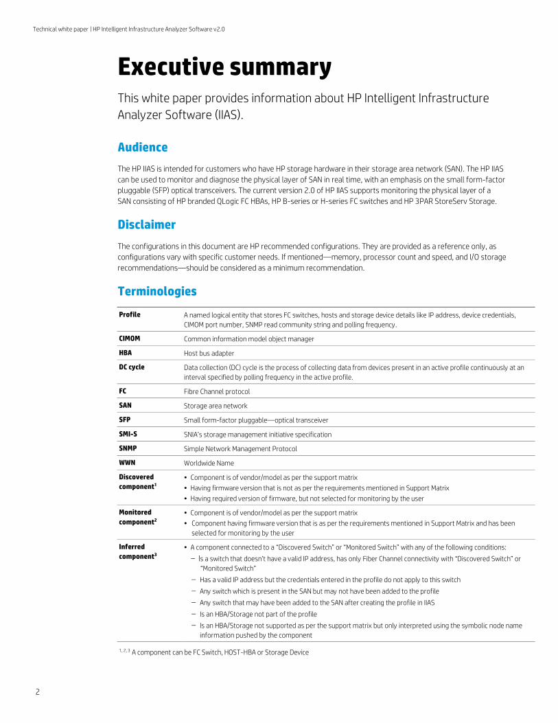
Terminologies
Profile A named logical entity that stores FC switches, hosts and storage device details like IP address, device credentials,
CIMOM port number, SNMP read community string and polling frequency.
CIMOM Common information model object manager
HBA Host bus adapter
DC cycle Data collection (DC) cycle is the process of collecting data from devices present in an active profile continuously at an
interval specified by polling frequency in the active profile.
FC Fibre Channel protocol
SAN Storage area network
SFP Small form-factor pluggable—optical transceiver
SMI-S SNIA’s storage management initiative specification
SNMP Simple Network Management Protocol
WWN Worldwide Name
Discovered
component1 • Component is of vendor/model as per the support matrix
• Having firmware version that is not as per the requirements mentioned in Support Matrix
• Having required version of firmware, but not selected for monitoring by the user
Monitored
component2
• Component is of vendor/model as per the support matrix
• Component having firmware version that is as per the requirements mentioned in Support Matrix and has been
selected for monitoring by the user
Inferred
component3 • A component connected to a “Discovered Switch” or “Monitored Switch” with any of the following conditions:
– Is a switch that doesn’t have a valid IP address, has only Fiber Channel connectivity with “Discovered Switch” or
“Monitored Switch”
– Has a valid IP address but the credentials entered in the profile do not apply to this switch
– Any switch which is present in the SAN but may not have been added to the profile
– Any switch that may have been added to the SAN after creating the profile in IIAS
– Is an HBA/Storage not part of the profile
– Is an HBA/Storage not supported as per the support matrix but only interpreted using the symbolic node name
information pushed by the component
1, 2, 3 A component can be FC Switch, HOST-HBA or Storage Device
Technical white paper | HP Intelligent Infrastructure Analyzer Software v2.0
3
Introduction
Unplanned downtime in data centers with storage network environments can result in significant cost to companies in
the form of lost revenue, productivity and other associated repercussions. Administrators in data centers spend a
considerable amount of time in monitoring and troubleshooting storage networking related issues. This is to mitigate
unplanned downtime owing to lack of effective diagnostic tools. One such time consuming task for administrators is
monitoring of storage networking optical links to detect and replace failing network components in a timely manner.
The prohibitive cost of application outages and associated administration has created a need for products that will enable
customers to anticipate and mitigate problems related storage networking optical links.
There is hence a need for continuous monitoring and rapid diagnostic capabilities for storage networking optical links,
to detect devices that are likely beginning to fail or failed, thereby anticipating and mitigating potential failures and reducing
the cost incurred due to unplanned application downtime.
IIAS is an online monitoring and diagnostic solution for the physical layer components such as SFPs on FC switches/
HBAs/HP 3PAR StoreServ storage devices across the SAN, diagnoses changes/events in the network and presents the
SAN diagnostic information along with inventory and topology to the user in real time.
This paper highlights the use model of IIAS in customer environments, example scenarios for monitoring/diagnosis and
troubleshooting optical transceiver issues, and, best practices in IIAS usage. Please refer to user guide and release
notes for product use and support matrix.
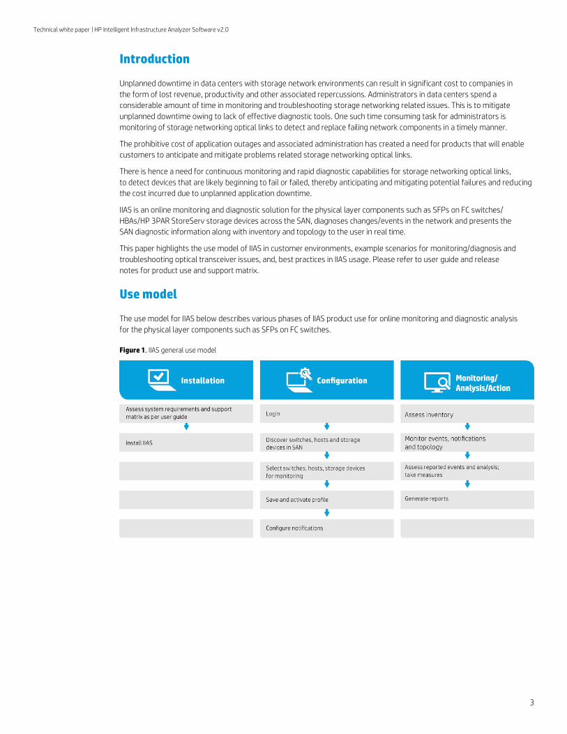
Use model
The use model for IIAS below describes various phases of IIAS product use for online monitoring and diagnostic analysis
for the physical layer components such as SFPs on FC switches.
Figure 1. IIAS general use model
Technical white paper | HP Intelligent Infrastructure Analyzer Software v2.0
4
Installation
Prior to IIAS installation, it is important to assess system requirements as per IIAS support matrix covering management
station requirements and fabric requirements of SAN to ensure smooth IIAS functionality after installation. User guide
details the environment prerequisites for IIAS installation.
Configuration
After IIAS installation, a user needs to configure IIAS before initiating monitoring and diagnostics of SFPs in the SAN. IIAS is configured by creating a Profile for the SAN components.
A profile can have details of multiple SAN components like FC switches, hosts and storage devices. There is no limit on
number of components that can be added to a profile. However, only one profile can be active at a time. SFPs of monitored components that are included in an active profile will be monitored and diagnosed. Terminologies section defines the
terms monitored, discovered and inferred component.
For IIAS to carry out SFP monitoring and diagnostics, the FC switches and HP 3PAR StoreServ in the SAN need to have a minimum version of firmware installed and hosts need to have HP branded QLogic 8/16 Gb HBAs. Appendix 4 lists support
matrix for SFP diagnostics.
Monitoring/Analysis/Action
This phase involves using various IIAS features covering inventory assessment, topology, event monitoring, and diagnosis
to monitor and analyze SAN events reported by IIAS. The IIAS reports SFP diagnostics as “Diagnostics Events”. A diagnostics
event is raised on the SAN Diagnostics page if SFPs are found to be degrading, degraded/failed. The topology screen also
highlights the affected link with color coding depending on whether the SFP is degrading or failed.
A user is provided with a facility to generate reports capturing the status of SAN. The report contains SAN inventory
summary, SAN details, event logs, diagnostics logs and topology snapshot of the SAN.
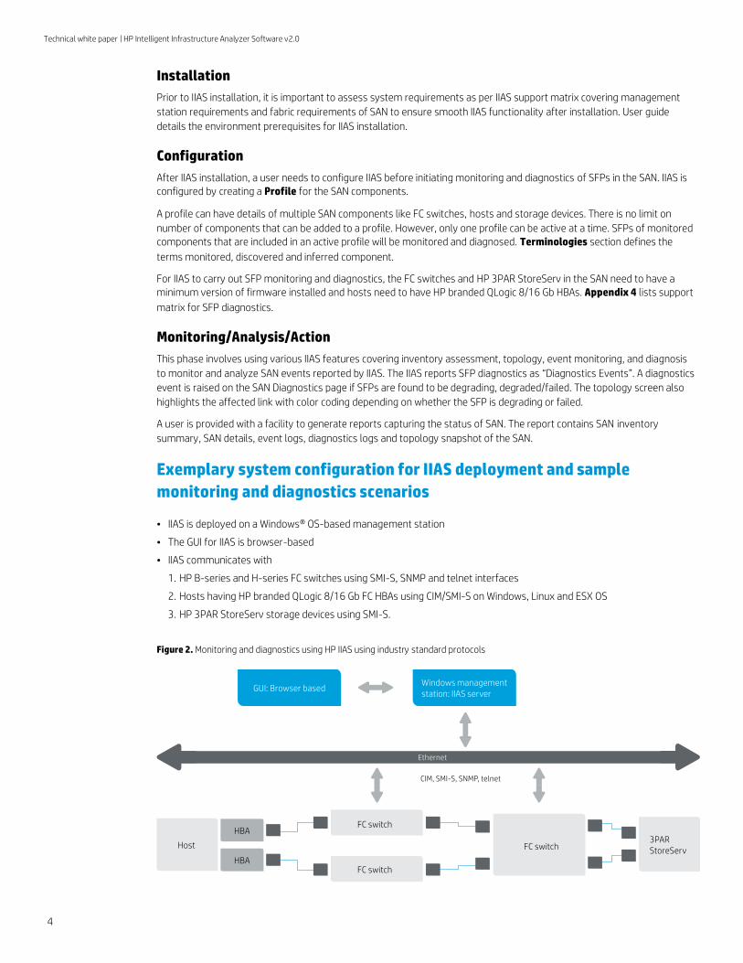
Exemplary system configuration for IIAS deployment and sample
monitoring and diagnostics scenarios
• IIAS is deployed on a Windows® OS-based management station
• The GUI for IIAS is browser-based
• IIAS communicates with
1. HP B-series and H-series FC switches using SMI-S, SNMP and telnet interfaces
2. Hosts having HP branded QLogic 8/16 Gb FC HBAs using CIM/SMI-S on Windows, Linux and ESX OS
3. HP 3PAR StoreServ storage devices using SMI-S.
Figure 2. Monitoring and diagnostics using HP IIAS using industry standard protocols
FC switch
Host
HBA
HBA
FC switch
Windows managementstation: IIAS server
GUI: Browser based
3PARStoreServ
FC switch
CIM, SMI-S, SNMP, telnet
Ethernet

Technical white paper | HP Intelligent Infrastructure Analyzer Software v2.0
5
The following sub sections cover sample scenarios for monitoring and troubleshooting optical transceiver issues using IIAS.
IIAS event pages and topology screen presented in the scenarios are extracts focusing on the essential aspects relating to
the diagnosis, and hence not exhaustive.
Sample scenario 1—Degrading SFP in ISL connection
Configuration:
This sample scenario covers detecting a situation wherein a SFP at one end of an ISL connection between 2 FC switches is
in a degrading state. Consider a FC switch with WWN 10:00:00:05:33:df:d3:7e, port 2 is connected to a FC switch with WWN
10:00:00:05:1e:03:9e:98, port 4. There is only one FC connection between these switches. The firmware of both switches is
supported by IIAS and one of the switches are selected for monitoring. For an ISL connection, IIAS can monitor SFPs at both
ends for effective diagnosis. We also consider the SFPs having a specification of Tx Power Warning threshold of 1100.0 uW.
Monitoring and diagnostics method:
Periodically monitor the diagnostic event page. In diagnostic event page, an event is raised by IIAS when it detects this
situation wherein the Tx Power parameter value of the SFP (on port 2 of SAN switch with WWN 10:00:00:05:33:df:d3:7e)
has crossed the “Warning” threshold. The SFP can be identified by its serial number, switch name, switch WWN and port
number provided in the event information.
The event here is tagged as “Major” in severity. This situation may be because of a degrading SFP at port 2 of the FC
switch with WWN 10:00:00:05:33:df:d3:7e. Impact of such a situation may eventually be the ISL connection loss, over a
period of time.
The user can view the topology page to visualize the connectivity information and impact wherein the connectivity color
associated with the degrading SFP will show amber.
If critical and major events are configured for notification, the user will receive all diagnostic related events through email.
The events associated with the SFP status are highlighted in the event display and topology snapshot extracts below as
blue and red boxes for easy identification in this white paper.
Figure 3. Scenario 1: HP IIAS events
In this scenario the topology shows the connectivity between the two switches in amber as the SFP is in degrading state.
Figure 4. Scenario 1: Topology view using HP IIAS
Technical white paper | HP Intelligent Infrastructure Analyzer Software v2.0
6
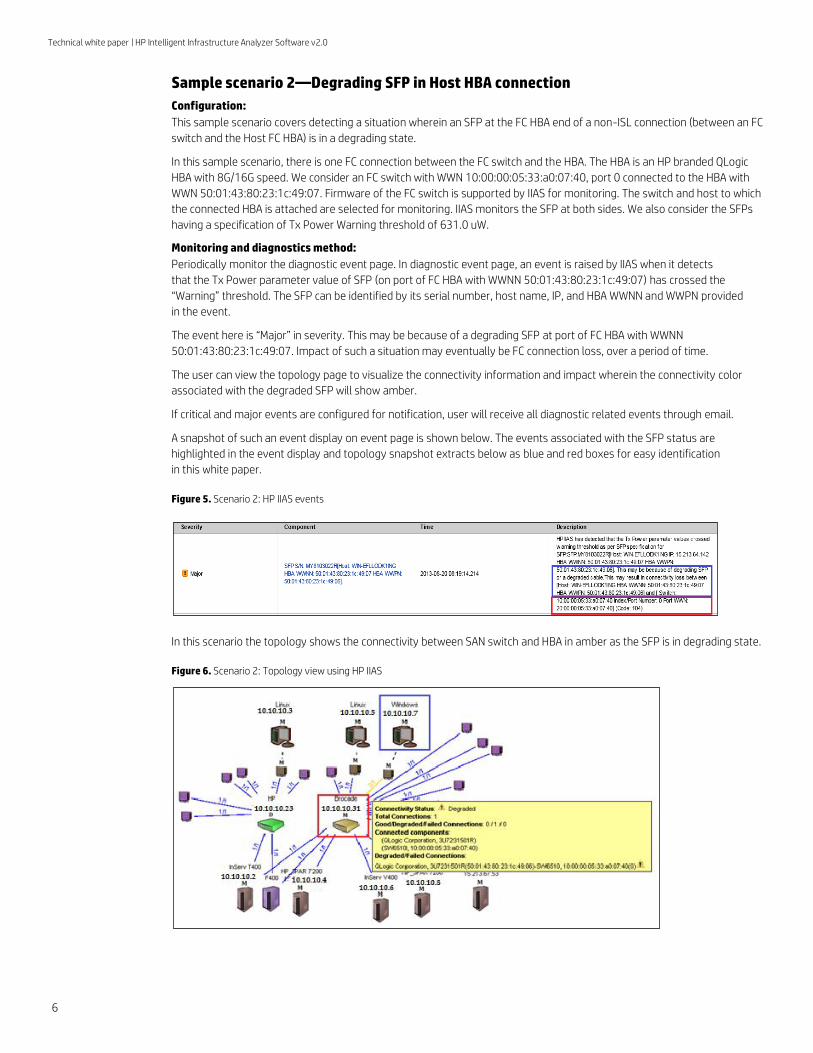
Sample scenario 2—Degrading SFP in Host HBA connection
Configuration:
This sample scenario covers detecting a situation wherein an SFP at the FC HBA end of a non-ISL connection (between an FC
switch and the Host FC HBA) is in a degrading state.
In this sample scenario, there is one FC connection between the FC switch and the HBA. The HBA is an HP branded QLogic
HBA with 8G/16G speed. We consider an FC switch with WWN 10:00:00:05:33:a0:07:40, port 0 connected to the HBA with
WWN 50:01:43:80:23:1c:49:07. Firmware of the FC switch is supported by IIAS for monitoring. The switch and host to which
the connected HBA is attached are selected for monitoring. IIAS monitors the SFP at both sides. We also consider the SFPs
having a specification of Tx Power Warning threshold of 631.0 uW.
Monitoring and diagnostics method:
Periodically monitor the diagnostic event page. In diagnostic event page, an event is raised by IIAS when it detects
that the Tx Power parameter value of SFP (on port of FC HBA with WWNN 50:01:43:80:23:1c:49:07) has crossed the
“Warning” threshold. The SFP can be identified by its serial number, host name, IP, and HBA WWNN and WWPN provided
in the event.
The event here is “Major” in severity. This may be because of a degrading SFP at port of FC HBA with WWNN
50:01:43:80:23:1c:49:07. Impact of such a situation may eventually be FC connection loss, over a period of time.
The user can view the topology page to visualize the connectivity information and impact wherein the connectivity color
associated with the degraded SFP will show amber.
If critical and major events are configured for notification, user will receive all diagnostic related events through email.
A snapshot of such an event display on event page is shown below. The events associated with the SFP status are
highlighted in the event display and topology snapshot extracts below as blue and red boxes for easy identification
in this white paper.
Figure 5. Scenario 2: HP IIAS events
In this scenario the topology shows the connectivity between SAN switch and HBA in amber as the SFP is in degrading state.
Figure 6. Scenario 2: Topology view using HP IIAS

Technical white paper | HP Intelligent Infrastructure Analyzer Software v2.0
7
Sample scenario 3—Degrading SFP at a switch port in a connection between a switch
and a storage
Configuration:
This sample scenario covers detecting a situation in a connection between a FC switch and a storage device. Both
components are monitored by IIAS. In this scenario the SFP on the FC switch side is the component in a degrading state.
We consider a FC switch with WWN 10:00:00:05:33:a0:07:40, port 4 is connected to the storage device with WWN
2f:f7:00:02:ac:00:0f:50 on port 2:2:3. There is only one FC connection between the components.
Consider the SFP having a Tx Power Warning threshold of 1100.0 uW.
Monitoring and diagnostics method:
Periodically monitor the diagnostic event page. In diagnostic event page, an event is raised by IIAS when it detects that
the Tx Power parameter value of SFP (on port 4 of SAN switch with WWN 10:00:00:05:33:a0:07:40) has crossed the
“Warning” threshold. The SFP can be identified by its serial number, switch name, switch WWN and port number provided
in the event information.
The event here is tagged “Major” in severity. This situation may be because of the degrading SFP at the switch end with
WWN 2f:f7:00:02:ac:00:0f:50, or a degraded cable or connector failure. Impact of such a situation may eventually be loss of
this connectivity to the storage device.
The user can view the topology page to visualize the connectivity information and impact wherein connectivity color
associated with the degraded SFP will show amber.
If critical and major events are configured for notification, user will receive all diagnostic related events through email.
The events associated with the SFP status are highlighted in the event display and topology snapshot extracts below as
blue and red boxes for easy identification in this white paper.
Figure 7. Scenario 3: HP IIAS events
In this scenario the topology shows the connectivity between FC switch and storage device in amber as the SFP is in
degrading state.
Figure 8. Scenario 3: Topology view using HP IIAS
Technical white paper | HP Intelligent Infrastructure Analyzer Software v2.0
8
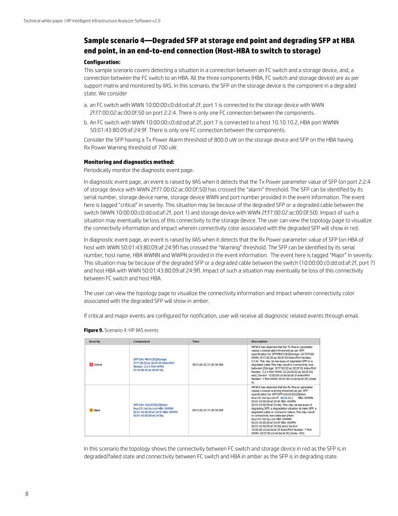
Sample scenario 4—Degraded SFP at storage end point and degrading SFP at HBA
end point, in an end-to-end connection (Host-HBA to switch to storage)
Configuration:
This sample scenario covers detecting a situation in a connection between an FC switch and a storage device, and, a
connection between the FC switch to an HBA. All the three components (HBA, FC switch and storage device) are as per
support matrix and monitored by IIAS. In this scenario, the SFP on the storage device is the component in a degraded
state. We consider
a. an FC switch with WWN 10:00:00:c0:dd:od:af:2f, port 1 is connected to the storage device with WWN
2f:f7:00:02:ac:00:0f:50 on port 2:2:4. There is only one FC connection between the components.
b. An FC switch with WWN 10:00:00:c0:dd:od:af:2f, port 7 is connected to a host 10.10.10.2, HBA port WWNN
50:01:43:80:09:af:24:9f. There is only one FC connection between the components.
Consider the SFP having a Tx Power Alarm threshold of 800.0 uW on the storage device and SFP on the HBA having
Rx Power Warning threshold of 700 uW.
Monitoring and diagnostics method:
Periodically monitor the diagnostic event page.
In diagnostic event page, an event is raised by IIAS when it detects that the Tx Power parameter value of SFP (on port 2:2:4
of storage device with WWN 2f:f7:00:02:ac:00:0f:50) has crossed the “alarm” threshold. The SFP can be identified by its
serial number, storage device name, storage device WWN and port number provided in the event information. The event
here is tagged “critical” in severity. This situation may be because of the degraded SFP or a degraded cable between the
switch (WWN 10:00:00:c0:dd:od:af:2f, port 1) and storage device with WWN 2f:f7:00:02:ac:00:0f:50). Impact of such a
situation may eventually be loss of this connectivity to the storage device. The user can view the topology page to visualize
the connectivity information and impact wherein connectivity color associated with the degraded SFP will show in red.
In diagnostic event page, an event is raised by IIAS when it detects that the Rx Power parameter value of SFP (on HBA of
host with WWN 50:01:43:80:09:af:24:9f) has crossed the “Warning” threshold. The SFP can be identified by its serial
number, host name, HBA WWNN and WWPN provided in the event information. The event here is tagged “Major” in severity.
This situation may be because of the degraded SFP or a degraded cable between the switch (10:00:00:c0:dd:od:af:2f, port 7)
and host HBA with WWN 50:01:43:80:09:af:24:9f). Impact of such a situation may eventually be loss of this connectivity
between FC switch and host HBA.
The user can view the topology page to visualize the connectivity information and impact wherein connectivity color
associated with the degraded SFP will show in amber.
If critical and major events are configured for notification, user will receive all diagnostic related events through email.
Figure 9. Scenario 4: HP IIAS events
In this scenario the topology shows the connectivity between FC switch and storage device in red as the SFP is in
degraded/failed state and connectivity between FC switch and HBA in amber as the SFP is in degrading state.
Technical white paper | HP Intelligent Infrastructure Analyzer Software v2.0
9
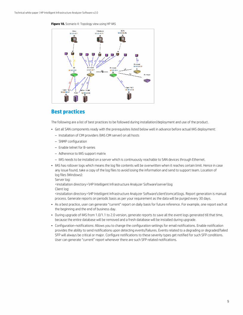
Figure 10. Scenario 4: Topology view using HP IIAS
Best practices
The following are a list of best practices to be followed during installation/deployment and use of the product.
• Get all SAN components ready with the prerequisites listed below well in advance before actual IIAS deployment:
– Installation of CIM providers (IIAS CIM server) on all hosts
– SNMP configuration
– Enable telnet for B-series
– Adherence to IIAS support matrix
– IIAS needs to be installed on a server which is continuously reachable to SAN devices through Ethernet.
• IIAS has rollover logs which means the log file contents will be overwritten when it reaches certain limit. Hence in case
any issue found, take a copy of the log files to avoid losing the information and send to support team. Location of
log files (Windows):
Server log:
<installation directory>\HP Intelligent Infrastructure Analyzer Software\server\log
Client log:
<installation directory>\HP Intelligent Infrastructure Analyzer Software\client\tomcat\logs. Report generation is manual
process. Generate reports on periodic basis as per your requirement as the data will be purged every 30 days.
• As a best practice, user can generate “current” report on daily basis for future reference. For example, one report each at
the beginning and the end of business day.
• During upgrade of IIAS from 1.0/1.1 to 2.0 version, generate reports to save all the event logs generated till that time,
because the entire database will be removed and a fresh database will be installed during upgrade.
• Configuration-notifications: Allows you to change the configuration settings for email notifications. Enable notification
provides the ability to send notifications upon detecting events/failures. Events related to a degrading or degraded/failed
SFP will always be critical or major. Configure notifications to these severity types get notified for such SFP conditions.
User can generate “current” report whenever there are such SFP related notifications.
Technical white paper | HP Intelligent Infrastructure Analyzer Software v2.0
10
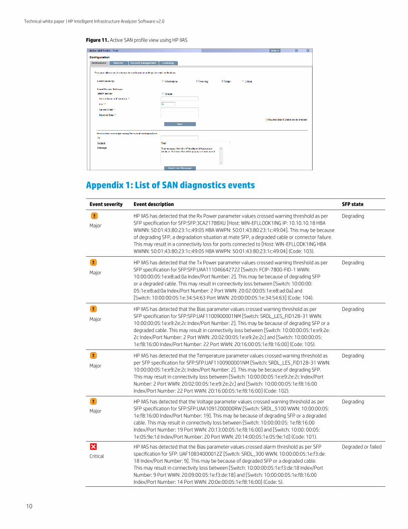
Figure 11. Active SAN profile view using HP IIAS
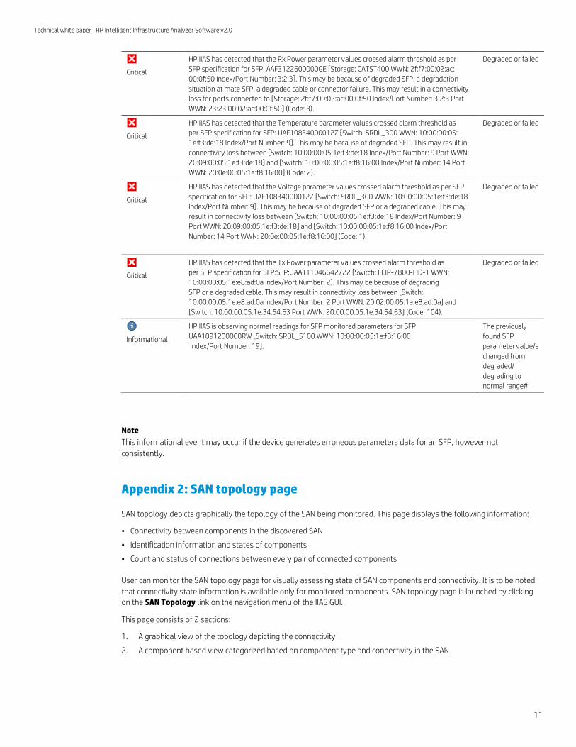
Appendix 1: List of SAN diagnostics events
Event severity Event description SFP state
Major
HP IIAS has detected that the Rx Power parameter values crossed warning threshold as per
SFP specification for SFP:SFP:3CA217BBXU [Host: WIN-EFLLODK1ING IP: 10.10.10.18 HBA
WWNN: 50:01:43:80:23:1c:49:05 HBA WWPN: 50:01:43:80:23:1c:49:04]. This may be because
of degrading SFP, a degradation situation at mate SFP, a degraded cable or connector failure.
This may result in a connectivity loss for ports connected to [Host: WIN-EFLLODK1ING HBA
WWNN: 50:01:43:80:23:1c:49:05 HBA WWPN: 50:01:43:80:23:1c:49:04] (Code: 103).
Degrading
Major
HP IIAS has detected that the Tx Power parameter values crossed warning threshold as per
SFP specification for SFP:SFP:UAA111046642722 [Switch: FCIP-7800-FID-1 WWN:
10:00:00:05:1e:e8:ad:0a Index/Port Number: 2]. This may be because of degrading SFP
or a degraded cable. This may result in connectivity loss between [Switch: 10:00:00:
05:1e:e8:ad:0a Index/Port Number: 2 Port WWN: 20:02:00:05:1e:e8:ad:0a] and
[Switch: 10:00:00:05:1e:34:54:63 Port WWN: 20:00:00:05:1e:34:54:63] (Code: 104).
Degrading
Major
HP IIAS has detected that the Bias parameter values crossed warning threshold as per
SFP specification for SFP:SFP:UAF1100900001NM [Switch: SRDL_LES_FID128-31 WWN:
10:00:00:05:1e:e9:2e:2c Index/Port Number: 2]. This may be because of degrading SFP or a
degraded cable. This may result in connectivity loss between [Switch: 10:00:00:05:1e:e9:2e:
2c Index/Port Number: 2 Port WWN: 20:02:00:05:1e:e9:2e:2c] and [Switch: 10:00:00:05:
1e:f8:16:00 Index/Port Number: 22 Port WWN: 20:16:00:05:1e:f8:16:00] (Code: 105).
Degrading
Major
HP IIAS has detected that the Temperature parameter values crossed warning threshold as
per SFP specification for SFP:SFP:UAF1100900001NM [Switch: SRDL_LES_FID128-31 WWN:
10:00:00:05:1e:e9:2e:2c Index/Port Number: 2]. This may be because of degrading SFP.
This may result in connectivity loss between [Switch: 10:00:00:05:1e:e9:2e:2c Index/Port
Number: 2 Port WWN: 20:02:00:05:1e:e9:2e:2c] and [Switch: 10:00:00:05:1e:f8:16:00
Index/Port Number: 22 Port WWN: 20:16:00:05:1e:f8:16:00] (Code: 102).
Degrading
Major
HP IIAS has detected that the Voltage parameter values crossed warning threshold as per
SFP specification for SFP:SFP:UAA1091200000RW [Switch: SRDL_5100 WWN: 10:00:00:05:
1e:f8:16:00 Index/Port Number: 19]. This may be because of degrading SFP or a degraded
cable. This may result in connectivity loss between [Switch: 10:00:00:05: 1e:f8:16:00
Index/Port Number: 19 Port WWN: 20:13:00:05:1e:f8:16:00] and [Switch: 10:00: 00:05:
1e:05:9e:1d Index/Port Number: 20 Port WWN: 20:14:00:05:1e:05:9e:1d] (Code: 101).
Degrading
Critical
HP IIAS has detected that the Bias parameter values crossed alarm threshold as per SFP
specification for SFP: UAF10834000012Z [Switch: SRDL_300 WWN: 10:00:00:05:1e:f3:de:
18 Index/Port Number: 9]. This may be because of degraded SFP or a degraded cable.
This may result in connectivity loss between [Switch: 10:00:00:05:1e:f3:de:18 Index/Port
Number: 9 Port WWN: 20:09:00:05:1e:f3:de:18] and [Switch: 10:00:00:05:1e:f8:16:00
Index/Port Number: 14 Port WWN: 20:0e:00:05:1e:f8:16:00] (Code: 5).
Degraded or failed
Technical white paper | HP Intelligent Infrastructure Analyzer Software v2.0
11
Critical
HP IIAS has detected that the Rx Power parameter values crossed alarm threshold as per
SFP specification for SFP: AAF3122600000GE [Storage: CATST400 WWN: 2f:f7:00:02:ac:
00:0f:50 Index/Port Number: 3:2:3]. This may be because of degraded SFP, a degradation
situation at mate SFP, a degraded cable or connector failure. This may result in a connectivity
loss for ports connected to [Storage: 2f:f7:00:02:ac:00:0f:50 Index/Port Number: 3:2:3 Port
WWN: 23:23:00:02:ac:00:0f:50] (Code: 3).
Degraded or failed
Critical
HP IIAS has detected that the Temperature parameter values crossed alarm threshold as
per SFP specification for SFP: UAF10834000012Z [Switch: SRDL_300 WWN: 10:00:00:05:
1e:f3:de:18 Index/Port Number: 9]. This may be because of degraded SFP. This may result in
connectivity loss between [Switch: 10:00:00:05:1e:f3:de:18 Index/Port Number: 9 Port WWN:
20:09:00:05:1e:f3:de:18] and [Switch: 10:00:00:05:1e:f8:16:00 Index/Port Number: 14 Port
WWN: 20:0e:00:05:1e:f8:16:00] (Code: 2).
Degraded or failed
Critical
HP IIAS has detected that the Voltage parameter values crossed alarm threshold as per SFP
specification for SFP: UAF10834000012Z [Switch: SRDL_300 WWN: 10:00:00:05:1e:f3:de:18
Index/Port Number: 9]. This may be because of degraded SFP or a degraded cable. This may
result in connectivity loss between [Switch: 10:00:00:05:1e:f3:de:18 Index/Port Number: 9
Port WWN: 20:09:00:05:1e:f3:de:18] and [Switch: 10:00:00:05:1e:f8:16:00 Index/Port
Number: 14 Port WWN: 20:0e:00:05:1e:f8:16:00] (Code: 1).
Degraded or failed
Critical
HP IIAS has detected that the Tx Power parameter values crossed alarm threshold as
per SFP specification for SFP:SFP:UAA111046642722 [Switch: FCIP-7800-FID-1 WWN:
10:00:00:05:1e:e8:ad:0a Index/Port Number: 2]. This may be because of degrading
SFP or a degraded cable. This may result in connectivity loss between [Switch:
10:00:00:05:1e:e8:ad:0a Index/Port Number: 2 Port WWN: 20:02:00:05:1e:e8:ad:0a] and
[Switch: 10:00:00:05:1e:34:54:63 Port WWN: 20:00:00:05:1e:34:54:63] (Code: 104).
Degraded or failed
Informational
HP IIAS is observing normal readings for SFP monitored parameters for SFP
UAA1091200000RW [Switch: SRDL_5100 WWN: 10:00:00:05:1e:f8:16:00
Index/Port Number: 19].
The previously
found SFP
parameter value/s
changed from
degraded/
degrading to
normal range#
Note
This informational event may occur if the device generates erroneous parameters data for an SFP, however not
consistently.
Appendix 2: SAN topology page
SAN topology depicts graphically the topology of the SAN being monitored. This page displays the following information:
• Connectivity between components in the discovered SAN
• Identification information and states of components
• Count and status of connections between every pair of connected components
User can monitor the SAN topology page for visually assessing state of SAN components and connectivity. It is to be noted
that connectivity state information is available only for monitored components. SAN topology page is launched by clicking
on the SAN Topology link on the navigation menu of the IIAS GUI.
This page consists of 2 sections:
1. A graphical view of the topology depicting the connectivity
2. A component based view categorized based on component type and connectivity in the SAN
Technical white paper | HP Intelligent Infrastructure Analyzer Software v2.0
12
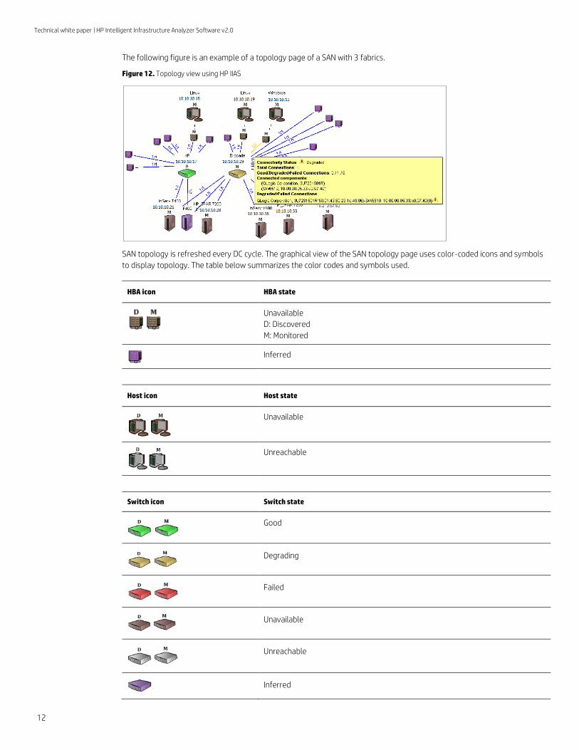
The following figure is an example of a topology page of a SAN with 3 fabrics.
Figure 12. Topology view using HP IIAS
SAN topology is refreshed every DC cycle. The graphical view of the SAN topology page uses color-coded icons and symbols
to display topology. The table below summarizes the color codes and symbols used.
HBA icon HBA state
Unavailable
D: Discovered
M: Monitored
Inferred
Host icon Host state
Unavailable
Unreachable
Switch icon Switch state
Good
Degrading
Failed
Unavailable
Unreachable
Inferred
Technical white paper | HP Intelligent Infrastructure Analyzer Software v2.0
13
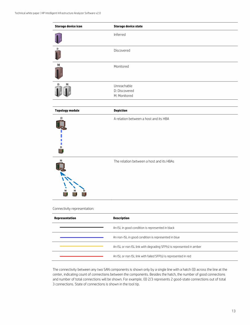
Storage device icon Storage device state
Inferred
Discovered
Monitored
Unreachable
D: Discovered
M: Monitored
Topology module Depiction
A relation between a host and its HBA
The relation between a host and its HBAs
Connectivity representation:
Representation Description
An ISL in good condition is represented in black
An non-ISL in good condition is represented in blue
An ISL or non ISL link with degrading SFP(s) is represented in amber
An ISL or non ISL link with failed SFP(s) is represented in red
The connectivity between any two SAN components is shown only by a single line with a hatch (||) across the line at the
center, indicating count of connections between the components. Besides the hatch, the number of good connections
and number of total connections will be shown. For example, (||) 2/3 represents 2 good-state connections out of total
3 connections. State of connections is shown in the tool tip.
Technical white paper | HP Intelligent Infrastructure Analyzer Software v2.0
14
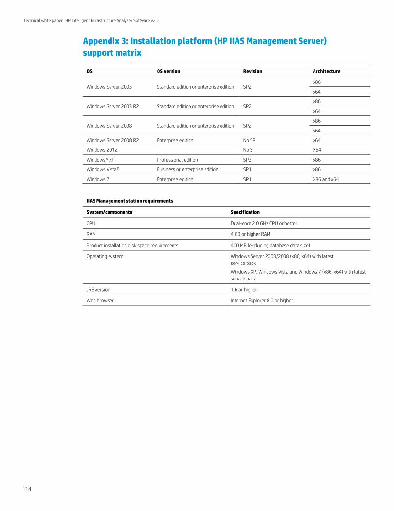
Appendix 3: Installation platform (HP IIAS Management Server)
support matrix
OS OS version Revision Architecture
Windows Server 2003 Standard edition or enterprise edition SP2 x86
x64
Windows Server 2003 R2 Standard edition or enterprise edition SP2 x86
x64
Windows Server 2008 Standard edition or enterprise edition SP2 x86
x64
Windows Server 2008 R2 Enterprise edition No SP x64
Windows 2012 No SP X64
Windows® XP Professional edition SP3 x86
Windows Vista® Business or enterprise edition SP1 x86
Windows 7 Enterprise edition SP1 X86 and x64
IIAS Management station requirements
System/components Specification
CPU Dual-core 2.0 GHz CPU or better
RAM 4 GB or higher RAM
Product installation disk space requirements 400 MB (excluding database data size)
Operating system Windows Server 2003/2008 (x86, x64) with latest
service pack
Windows XP, Windows Vista and Windows 7 (x86, x64) with latest
service pack
JRE version 1.6 or higher
Web browser Internet Explorer 8.0 or higher

Technical white paper | HP Intelligent Infrastructure Analyzer Software v2.0
Sign up for updates
hp.com/go/getupdated
Share with colleagues
Rate this document
© Copyright 2012-2013 Hewlett-Packard Development Company, L.P. The information contained herein is subject to change without notice. The only warranties for
HP products and services are set forth in the express warranty statements accompanying such products and services. Nothing herein should be construed as
constituting an additional warranty. HP shall not be liable for technical or editorial errors or omissions contained herein.
Windows, Windows XP, and Windows Vista are U.S. registered trademarks of Microsoft Corporation.
4AA4-4656ENW, September, Rev. 1
Appendix 4: Support matrix
Operating systems supported for HP IIAS CIM Server
Operating system Platform Version
Windows 32-bit, 64-bit 2003, 2008 SP2, 2008 R2, and 2012
Red Hat Enterprise Linux (RHEL) 32-bit, 64-bit 5.8, 5.9, 6.3, 6.4
SUSE Linux Enterprise (SLES) 32-bit, 64-bit 11 SP2, SP3
VMware ESXi 64-bit 5.0, 5.1, and 5.5
Switch/HBA/storage device monitoring
SAN component Monitoring support
Switch B-series Firmware 7.x
Switch H-series Firmware 8.0.14.03.00 or 8.0.4.04.00 or higher
HP Branded QLogic HBA 16/8 Gb QLogic HBA
HP 3PAR StoreServ Firmware 3.1.2 or above
Learn more at
hp.com/go/iias