20onl
DESCRIPTION
http://www.usfirst.org/uploadedFiles/Community/FRC/Game_and_Season__Info/2010_Assets/Reference%20only%202009%20Frame%20Assembly.pdfTRANSCRIPT

2009 Frame Assembly Instructions
These are the frame assembly instructions for 2009 and do not reflect the minor changes of the 2010 version. They are provided to give you some idea of what is required to assemble the frame.
2009 Frame Assembly – Reference Only

Final Product PictureYou will be making a 27” x 37” robot: 27” front and back, with 37” sides
2009 Frame Assembly – Reference Only

This is what you should have: 4 original rails, 2 rails cut to 27”
Save the 8” cut pieces for thisyear’s robot …..
File the ends afterthey are cut.
Have 2 of the 6 rails cut at the cutting stationto make them 27” long. There is a reference hole marking this location on each rail.
2009 Frame Assembly – Reference Only

Insert the frame connectors into the end holes of the 4 longrails (not the 2 cut ones) until you can get a 1.75” long frame bolt through the ‘ears’ on the connector. It is a tight fit so you might have to tap them in.
Put the nylock nuts on but do not tighten them yet.
Repeat for both ends of all 4 long rails. Leave the nylock nuts loose.
2009 Frame Assembly – Reference Only

Repeat to assemble the inner frame. When you are done it should look like this.
27” cut railLong rail
This frame connector goes inthe 4th and 5th holes from theend of the cut rail.
Install Nylock nuts but do not tighten.
2009 Frame Assembly – Reference Only

Use a non-mar hammer for the bearings;if not available, cushion the hammer taps with a block of wood or similar material.
Make sure the bearings are bottomed-outin the wheel hub recess. They should only stick out about 1/8” inch.
Be sure and add the spacer! It will keep the chain from rubbing the wheel.
2009 Frame Assembly – Reference Only

Use a low clutch settingon the drill to avoidstripping the threadsin the plastic.
Self-tapping 10-24screws, 1” long (from the‘sandwich’ bag); 3 perwheel is sufficient.
You only have to putsprockets on 2 wheelstoday, but you can put all 4 on if you think you want to try 4-wheel drive later.
2009 Frame Assembly – Reference Only

Gather these parts.
Assemble the other wheel, reversing the spacers if you intend to try 4-wheel chain drive later. If not, the spacer order does not matter as long as you use one long and one short.
Long outer rail End rail
Make sure the sprocket faces the inside of the frame(Note: You cannot see the sprocket in this view)
Short spacer
Long innerrail
Long spacer
2009 Frame Assembly – Reference Only

Push the frame connectors into the end rails and bolt them up.
Note: If the frame connectors on the long rails do not go in far enough to get the frame bolts through, you may not have driven the wheel bearings in all the way. Disassemble and correct.
Tighten all the frame bolts!
Notice the staggered sprocket pattern of the two wheels to allow for optional 4-wheel chain drive later.
2009 Frame Assembly – Reference Only

Attach the transmissions using the short ¼-20 screws and put the nylock nuts on loose. The exact location of the transmission box on the frame is not critical but it should be 1/3-1/2 of the way down the frame for this lay-out. You can change this at a later date if you want.Note: There should be ‘left’ and ‘right’ transmissions made so that the motors are both towards the center of the robot for better weight distribution. But this is not critical.
Measure where the chain needs to be cut: drape the chain over both sprockets, slide the transmission to the end of its slots, and identify the link to cut.If you have never measured or cut chain before, ask a mentor to help you.
Motor closer to the center of the robot.
Push to the end of the slot.
2009 Frame Assembly – Reference Only
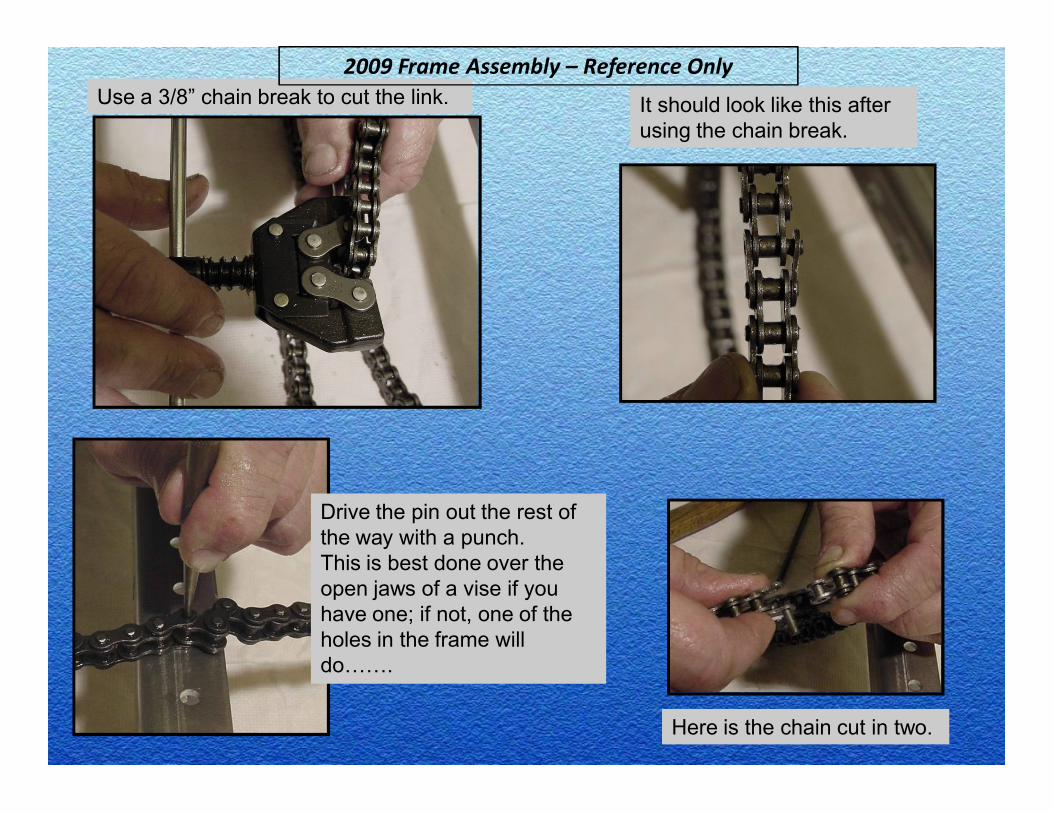
Use a 3/8” chain break to cut the link. It should look like this afterusing the chain break.
Drive the pin out the rest of the way with a punch. This is best done over the open jaws of a vise if you have one; if not, one of the holes in the frame will do…….
Here is the chain cut in two.
2009 Frame Assembly – Reference Only
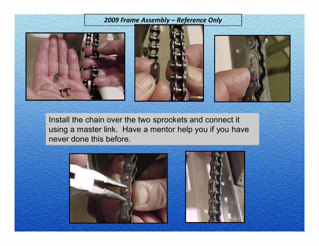
Install the chain over the two sprockets and connect it using a master link. Have a mentor help you if you have never done this before.
2009 Frame Assembly – Reference Only

Push the transmission box to tighten the chain and then tighten all 4 bolts.
Repeat for the other side, remembering it is preferred to have the motors face each other and be towards the center of the robot.If your transmissions are not left/right this is OK as it is only for better weight distribution. If you want, you could have the Transmission Team change the motor orientation – it’s not that hard.
2009 Frame Assembly – Reference Only

Finished robot frame below. You cannot continue until the Electronics Team is ready with their board.
Note: Hold onto the (3) ¼-20 x 1.75” bolts and Nylock nuts that were in your ‘sandwich’ bag. You will need them to help mount the electronics board to the frame.
2009 Frame Assembly – Reference Only