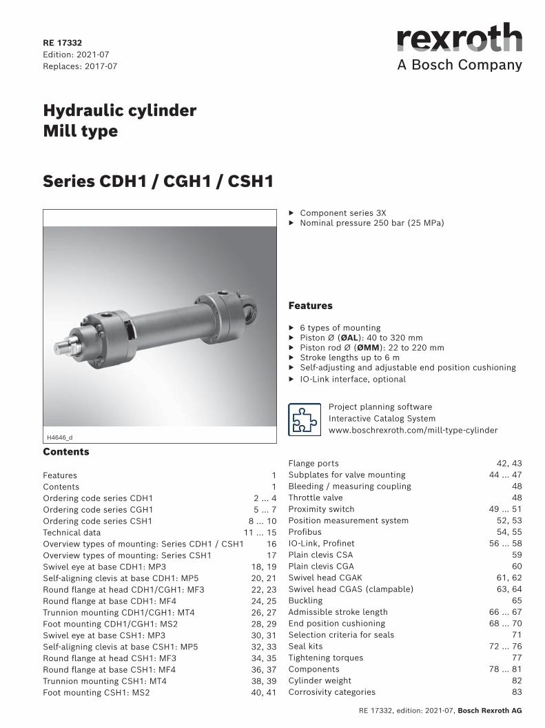
hydraulic cylinder mill type
TRANSCRIPT
RE 17332, edition: 2021-07, Bosch Rexroth AG
Hydraulic cylinder Mill type
Component series 3X Nominal pressure 250 bar (25 MPa)
H4646_d
Series CDH1 / CGH1 / CSH1
RE 17332Edition: 2021-07Replaces: 2017-07
Features
6 types of mounting Piston Ø (ØAL): 40 to 320 mm Piston rod Ø (ØMM): 22 to 220 mm Stroke lengths up to 6 m Self-adjusting and adjustable end position cushioning IO-Link interface, optional
Contents
Features 1Contents 1Ordering code series CDH1 2 … 4Ordering code series CGH1 5 … 7Ordering code series CSH1 8 … 10Technical data 11 … 15Overview types of mounting: Series CDH1 / CSH1 16Overview types of mounting: Series CSH1 17Swivel eye at base CDH1: MP3 18, 19Self-aligning clevis at base CDH1: MP5 20, 21Round flange at head CDH1/CGH1: MF3 22, 23Round flange at base CDH1: MF4 24, 25Trunnion mounting CDH1/CGH1: MT4 26, 27Foot mounting CDH1/CGH1: MS2 28, 29Swivel eye at base CSH1: MP3 30, 31Self-aligning clevis at base CSH1: MP5 32, 33Round flange at head CSH1: MF3 34, 35Round flange at base CSH1: MF4 36, 37Trunnion mounting CSH1: MT4 38, 39Foot mounting CSH1: MS2 40, 41
Flange ports 42, 43Subplates for valve mounting 44 … 47Bleeding / measuring coupling 48Throttle valve 48Proximity switch 49 … 51Position measurement system 52, 53 Profibus 54, 55IO-Link, Profinet 56 … 58Plain clevis CSA 59Plain clevis CGA 60Swivel head CGAK 61, 62Swivel head CGAS (clampable) 63, 64Buckling 65Admissible stroke length 66 … 67End position cushioning 68 … 70Selection criteria for seals 71Seal kits 72 … 76 Tightening torques 77Components 78 … 81Cylinder weight 82Corrosivity categories 83
Project planning software Interactive Catalog System www.boschrexroth.com/mill-type-cylinder
Inhalt
Features 1Ordering code series CDH1 2Ordering code series CDH1 3Ordering code series CDH1 (fields for additional options) 4Ordering code series CGH1 5Ordering code series CGH1 6Ordering code series CGH1 (fields for additional options) 7Ordering code series CSH1 8Ordering code series CSH1 9Ordering code series CSH1 (fields for additional options) 10Technical data (For applications outside these values, please consult us!) 11Technical data (For applications outside these values, please consult us!) 12Technical data (For applications outside these values, please consult us!) 13Technical data (For applications outside these values, please consult us!) 14Technical data (For applications outside these values, please consult us!) 15Overview types of mounting: Series CDH1 / CGH1 16Overview types of mounting: Series CSH1 17Dimensions Swivel eye at base CDH1: MP3 (dimensions in mm) 18Dimensions Swivel eye at base CDH1: MP3 (dimensions in mm) 19Dimensions Self-aligning clevis at base CDH1: MP5 (dimensions in mm) 20Dimensions Self-aligning clevis at base CDH1: MP5 (dimensions in mm) 21Dimensions Round flange at head CDH1/CGH1: MF3 (dimensions in mm) 22Dimensions Round flange at head CDH1/CGH1: MF3 (dimensions in mm) 23Dimensions Round flange at base CDH1: MF4 (dimensions in mm) 24Dimensions Round flange at base CDH1: MF4 (dimensions in mm) 25Dimensions Trunnion mounting CDH1/CGH1: MT4 (dimensions in mm) 26Dimensions Trunnion mountings CDH1/CGH1: MT4 (dimensions in mm) 27Dimensions Foot mounting CDH1/CGH1: MS2 (dimensions in mm) 28Dimensions Foot mounting CDH1/CGH1: MS2 (dimensions in mm) 29Dimensions Swivel eye at base CSH1: MP3 (dimensions in mm) 30Dimensions Swivel eye at base CSH1: MP3 (dimensions in mm) 31Dimensions Self-aligning clevis at base CSH1: MP5 (dimensions in mm) 32Dimensions Self-aligning clevis at base CSH1: MP5 (dimensions in mm) 33Dimensions Round flange at head CSH1: MF3 (dimensions in mm) 34Dimensions Round flange at head CSH1: MF3 (dimensions in mm) 35Dimensions Round flange at base CSH1: MF4 (dimensions in mm) 36Dimensions Round flange at base CSH1: MF4 (dimensions in mm) 37Dimensions Trunnion mounting CSH1: MT4 (dimensions in mm) 38Dimensions Trunnion mounting CSH1: MT4 (dimensions in mm) 39Dimensions Foot mounting CSH1: MS2 (dimensions in mm) 40Dimensions Foot mounting CSH1: MS2 (dimensions in mm) 41Dimensions: Flange ports (dimensions in mm) 42Dimensions: Flange ports (dimensions in mm) 43Dimensions: Subplates for valve mounting (SL and SV valve) (dimensions in mm) 44Dimensions: Subplates for valve mounting (SL and SV valve) (dimensions in mm) 45Dimensions: Subplates for valve mounting (directional and control valves) (dimensions in mm) 46Dimensions: Subplates for valve mounting (directional and control valves) (dimensions in mm) 47Bleeding / measuring coupling (dimensions in mm) 48Dimensions: Throttle valve (dimensions in mm) 48Proximity switch (dimensions in mm) 49Technical data (For applications outside these values, please consult us!) 49Dimensions: Proximity switch (dimensions in mm) 50Dimensions: Proximity switch (dimensions in mm) 51Position measurement system 52Technical data: Analog output (For applications outside these values, please consult us!) 52Technical data: Digital output (For applications outside these values, please consult us!) 53Technical data: Profibus (For applications outside these values, please consult us!) 54Pin assignment for Profibus 54Technical data: IO-Link (For applications outside these values, please consult us!) 56Technical data: Profinet (For applications outside these values, please consult us!) 57Technical data: Profinet 58Plain clevis CSA (dimensions in mm) 59Swivel head CGA (dimensions in mm) 60Swivel head CGAK (clampable) (dimensions in mm) 61Swivel head CGAK (clampable) (dimensions in mm) 62Swivel head CGAS (clampable) (dimensions in mm) 63Swivel head CGAS (clampable) (dimensions in mm) 64Buckling 65Admissible stroke length (dimensions in mm) 65Admissible stroke length (dimensions in mm) 66Admissible stroke length (dimensions in mm) 67End position cushioning 68End position cushioning 69End position cushioning 70Selection criteria for seals 71Seal kits 1) 72
Seal kits 1) 73
Seal kits 1) 74
Seal kits 2) 75
Seal kits 76Tightening torques 77Components: Series CDH1 78Components: Series CGH1 79Components: Series CSH1 MP3 and MP5 80Components: Series CSH1 MF3, MF4, MT4 and MS2 81Cylinder weight 82Corrosivity categories 83
2/84 Series CDH1 /CGH1 / CSH1 | Hydraulic cylinder mill type
Bosch Rexroth AG, RE 17332, edition: 2021-07
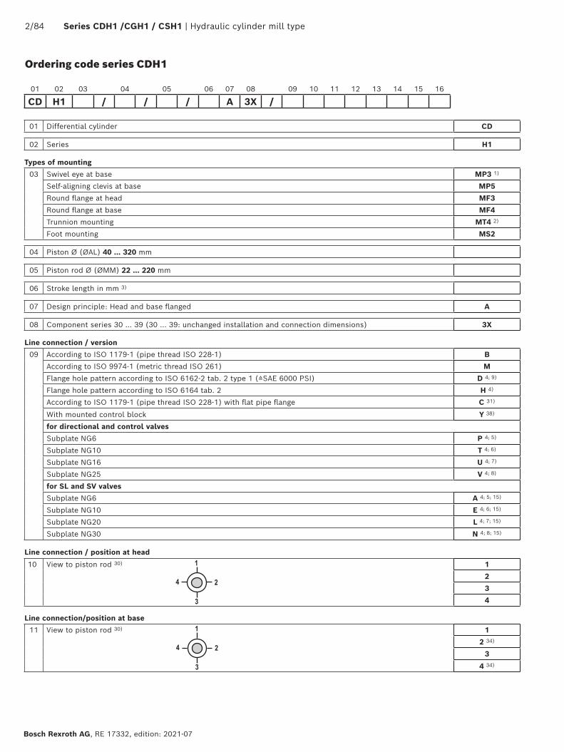
Ordering code series CDH1
01 Differential cylinder CD
02 Series H1
Types of mounting
03 Swivel eye at base MP3 1)
Self-aligning clevis at base MP5
Round flange at head MF3
Round flange at base MF4
Trunnion mounting MT4 2)
Foot mounting MS2
04 Piston Ø (ØAL) 40 … 320 mm
05 Piston rod Ø (ØMM) 22 … 220 mm
06 Stroke length in mm 3)
07 Design principle: Head and base flanged A
08 Component series 30 … 39 (30 … 39: unchanged installation and connection dimensions) 3X
Line connection / version
09 According to ISO 1179-1 (pipe thread ISO 228-1) B
According to ISO 9974-1 (metric thread ISO 261) M
Flange hole pattern according to ISO 6162-2 tab. 2 type 1 (≙SAE 6000 PSI) D 4; 9)
Flange hole pattern according to ISO 6164 tab. 2 H 4)
According to ISO 1179-1 (pipe thread ISO 228-1) with flat pipe flange C 31)
With mounted control block Y 38)
for directional and control valves
Subplate NG6 P 4; 5)
Subplate NG10 T 4; 6)
Subplate NG16 U 4; 7)
Subplate NG25 V 4; 8)
for SL and SV valves
Subplate NG6 A 4; 5; 15)
Subplate NG10 E 4; 6; 15)
Subplate NG20 L 4; 7; 15)
Subplate NG30 N 4; 8; 15)
Line connection / position at head
10 View to piston rod 30) 1
2
3
4
Line connection/position at base
11 View to piston rod 30) 1
2 34)
3
4 34)
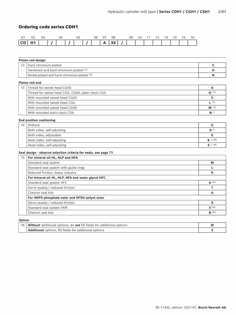
01 02 03 04 05 06 07 08 09 10 11 12 13 14 15 16
CD H1 / / / A 3X /
Hydraulic cylinder mill type | Series CDH1 / CGH1 / CSH1 3/84
RE 17332, edition: 2021-07, Bosch Rexroth AG
Ordering code series CDH1
Piston rod design
12 Hard chromium-plated C
Hardened and hard chromium-plated 12) H
Nickel-plated and hard chromium-plated 19) N
Piston rod end
13 Thread for swivel head CGAS A
Thread for swivel head CGA, CGAK, plain clevis CSA G 13)
With mounted swivel head CGAS S
With mounted swivel head CGA L 13)
With mounted swivel head CGAK M 13)
With mounted plain clevis CSA N 1)
End position cushioning
14 Without U
Both sides, self-adjusting D 1)
Both sides, adjustable E
Base sides, self-adjusting K 1; 38)
Head sides, self-adjusting S 1; 38)
Seal design - observe selection criteria for seals, see page 71
15 For mineral oil HL, HLP and HFA
Standard seal system M
Standard seal system with guide rings L
Reduced friction, heavy industry R
For mineral oil HL, HLP, HFA and water glycol HFC
Standard seal system HFC G 40)
Servo quality / reduced friction T
Chevron seal kits A
For HDFR phosphate ester and HFDU polyol ester
Servo quality / reduced friction S
Standard seal system FKM V 40)
Chevron seal kits B 39)
Option
16 Without additional options, do not fill fields for additional options W
Additional options, fill fields for additional options Z
01 02 03 04 05 06 07 08 09 10 11 12 13 14 15 16
CD H1 / / / A 3X /
4/84 Series CDH1 /CGH1 / CSH1 | Hydraulic cylinder mill type
Bosch Rexroth AG, RE 17332, edition: 2020-XX
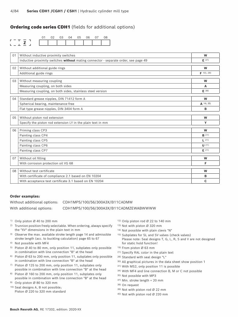
Ordering code series CDH1 (fields for additional options)
01 02 03 04 05 06 07 08
Z
01 Without inductive proximity switches W
Inductive proximity switches without mating connector - separate order, see page 49 E 37)
02 Without additional guide rings W
Additional guide rings F 10), 28)
03 Without measuring coupling W
Measuring coupling, on both sides A
Measuring coupling, on both sides, stainless steel version E 38)
04 Standard grease nipples, DIN 71412 form A W
Spherical bearing, maintenance-free A 14), 35)
Flat type grease nipples, DIN 3404 form A B
05 Without piston rod extension W
Specify the piston rod extension LY in the plain text in mm Y
06 Priming class CP3 W
Painting class CP4 B 21)
Painting class CP5 L 21)
Painting class CP6 U 21)
Painting class CP7 E 21)
07 Without oil filling W
With corrosion protection oil VG 68 F
08 Without test certificate W
With certificate of compliance 2.1 based on EN 10204 B
With acceptance test certificate 3.1 based on EN 10204 C
Order examples:
Without additional options: CDH1MP5/100/56/300A3X/B11CADMW
With additional options: CDH1MP5/100/56/300A3X/B11CADMZEWABWWWW
1) Only piston Ø 40 to 200 mm2) Trunnion position freely selectable. When ordering, always specify
the "XV" dimensions in the plain text in mm3) Observe the max. available stroke length page 14 and admissible
stroke length (acc. to buckling calculation) page 65 to 674) Not possible with MF45) Piston Ø 40 to 80 mm, only position 11, subplates only possible
in combination with line connection "B" at the head6) Piston Ø 63 to 200 mm, only position 11, subplates only possible
in combination with line connection "B" at the head7) Piston Ø 125 to 200 mm, only position 11, subplates only
possible in combination with line connection "B" at the head8) Piston Ø 160 to 200 mm, only position 11, subplates only
possible in combination with line connection "B" at the head9) Only piston Ø 80 to 320 mm10) Seal designs A, B not possible;
Piston Ø 220 to 320 mm standard
12) Only piston rod Ø 22 to 140 mm13) Not with piston Ø 320 mm14) Not possible with plain clevis "N"15) Subplates for SL and SV valves (check valves)
Please note: Seal designs T, G, L, R, S and V are not designed for static hold function!
19) From piston Ø 63 mm21) Specify RAL color in the plain text28) Standard with seal design "L"30) All graphical pictures in the data sheet show position 131) With MS2, only position 11 is possible34) With MF4 and line connection B, M or C not possible35) Not possible with MP337) Min. stroke length = 20 mm38) On request39) Not with piston rod Ø 22 mm40) Not with piston rod Ø 220 mm
Hydraulic cylinder mill type | CDH1 / CGH1 / CSH1 5/84
RE 17332, edition: 2020-XX, Bosch Rexroth AG
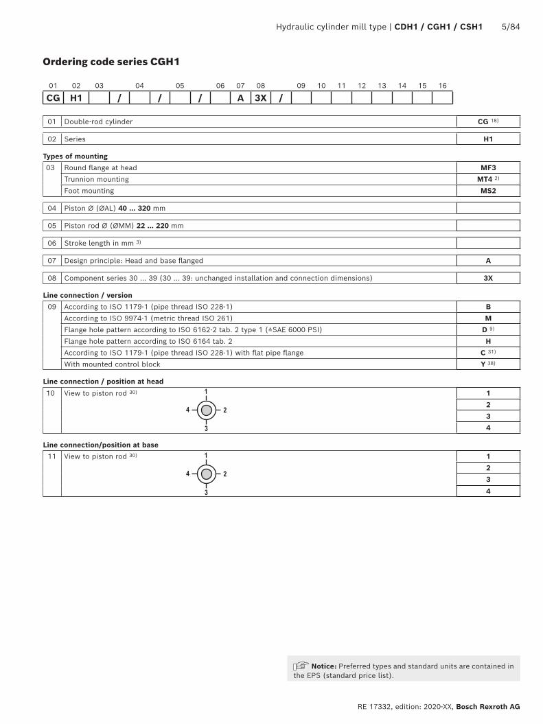
Ordering code series CGH1
01 Double-rod cylinder CG 18)
02 Series H1
Types of mounting
03 Round flange at head MF3
Trunnion mounting MT4 2)
Foot mounting MS2
04 Piston Ø (ØAL) 40 … 320 mm
05 Piston rod Ø (ØMM) 22 … 220 mm
06 Stroke length in mm 3)
07 Design principle: Head and base flanged A
08 Component series 30 … 39 (30 … 39: unchanged installation and connection dimensions) 3X
Line connection / version
09 According to ISO 1179-1 (pipe thread ISO 228-1) B
According to ISO 9974-1 (metric thread ISO 261) M
Flange hole pattern according to ISO 6162-2 tab. 2 type 1 (≙SAE 6000 PSI) D 9)
Flange hole pattern according to ISO 6164 tab. 2 H
According to ISO 1179-1 (pipe thread ISO 228-1) with flat pipe flange C 31)
With mounted control block Y 38)
Line connection / position at head
10 View to piston rod 30) 1
2
3
4
Line connection/position at base
11 View to piston rod 30) 1
2
3
4
01 02 03 04 05 06 07 08 09 10 11 12 13 14 15 16
CG H1 / / / A 3X /
Notice: Preferred types and standard units are contained in the EPS (standard price list).
6/84 Series CDH1 /CGH1 / CSH1 | Hydraulic cylinder mill type
Bosch Rexroth AG, RE 17332, edition: 2021-07
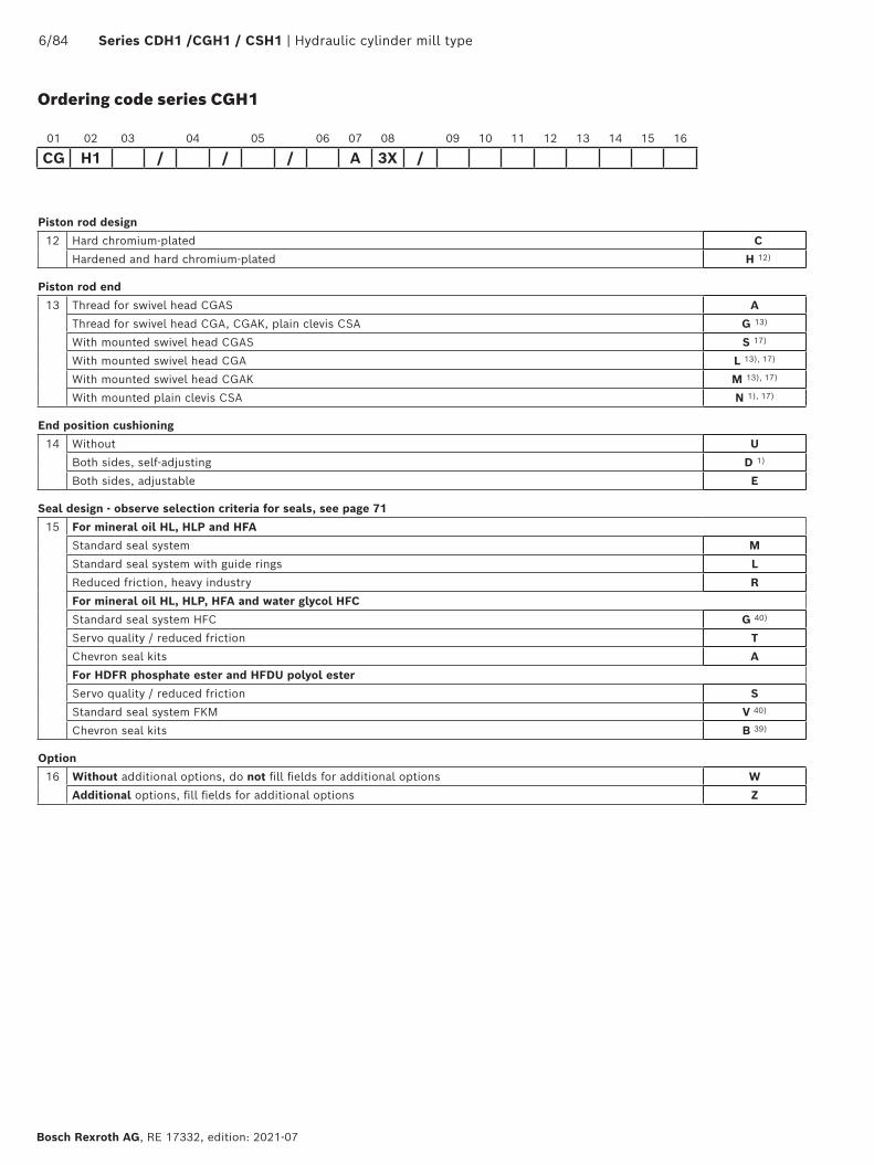
Ordering code series CGH1
Piston rod design
12 Hard chromium-plated C
Hardened and hard chromium-plated H 12)
Piston rod end
13 Thread for swivel head CGAS A
Thread for swivel head CGA, CGAK, plain clevis CSA G 13)
With mounted swivel head CGAS S 17)
With mounted swivel head CGA L 13), 17)
With mounted swivel head CGAK M 13), 17)
With mounted plain clevis CSA N 1), 17)
End position cushioning
14 Without U
Both sides, self-adjusting D 1)
Both sides, adjustable E
Seal design - observe selection criteria for seals, see page 71
15 For mineral oil HL, HLP and HFA
Standard seal system M
Standard seal system with guide rings L
Reduced friction, heavy industry R
For mineral oil HL, HLP, HFA and water glycol HFC
Standard seal system HFC G 40)
Servo quality / reduced friction T
Chevron seal kits A
For HDFR phosphate ester and HFDU polyol ester
Servo quality / reduced friction S
Standard seal system FKM V 40)
Chevron seal kits B 39)
Option
16 Without additional options, do not fill fields for additional options W
Additional options, fill fields for additional options Z
01 02 03 04 05 06 07 08 09 10 11 12 13 14 15 16
CG H1 / / / A 3X /
Hydraulic cylinder mill type | Series CDH1 / CGH1 / CSH1 7/84
RE 17332, edition: 2021-07, Bosch Rexroth AG
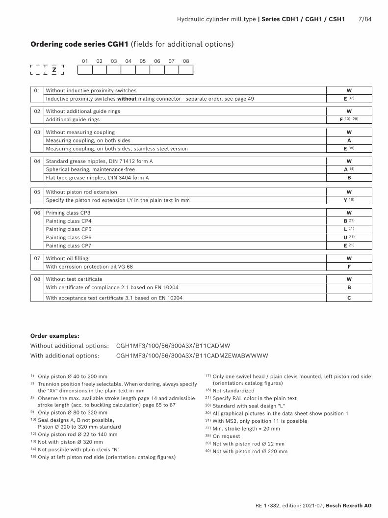
Ordering code series CGH1 (fields for additional options)
01 02 03 04 05 06 07 08
Z
01 Without inductive proximity switches W
Inductive proximity switches without mating connector - separate order, see page 49 E 37)
02 Without additional guide rings W
Additional guide rings F 10), 28)
03 Without measuring coupling W
Measuring coupling, on both sides A
Measuring coupling, on both sides, stainless steel version E 38)
04 Standard grease nipples, DIN 71412 form A W
Spherical bearing, maintenance-free A 14)
Flat type grease nipples, DIN 3404 form A B
05 Without piston rod extension W
Specify the piston rod extension LY in the plain text in mm Y 16)
06 Priming class CP3 W
Painting class CP4 B 21)
Painting class CP5 L 21)
Painting class CP6 U 21)
Painting class CP7 E 21)
07 Without oil filling W
With corrosion protection oil VG 68 F
08 Without test certificate W
With certificate of compliance 2.1 based on EN 10204 B
With acceptance test certificate 3.1 based on EN 10204 C
Order examples:
Without additional options: CGH1MF3/100/56/300A3X/B11CADMW
With additional options: CGH1MF3/100/56/300A3X/B11CADMZEWABWWWW
1) Only piston Ø 40 to 200 mm2) Trunnion position freely selectable. When ordering, always specify
the "XV" dimensions in the plain text in mm3) Observe the max. available stroke length page 14 and admissible
stroke length (acc. to buckling calculation) page 65 to 679) Only piston Ø 80 to 320 mm10) Seal designs A, B not possible;
Piston Ø 220 to 320 mm standard12) Only piston rod Ø 22 to 140 mm13) Not with piston Ø 320 mm14) Not possible with plain clevis "N"16) Only at left piston rod side (orientation: catalog figures)
17) Only one swivel head / plain clevis mounted, left piston rod side (orientation: catalog figures)
18) Not standardized21) Specify RAL color in the plain text28) Standard with seal design "L"30) All graphical pictures in the data sheet show position 131) With MS2, only position 11 is possible37) Min. stroke length = 20 mm38) On request39) Not with piston rod Ø 22 mm40) Not with piston rod Ø 220 mm

8/84 Series CDH1 /CGH1 / CSH1 | Hydraulic cylinder mill type
Bosch Rexroth AG, RE 17332, edition: 2021-07
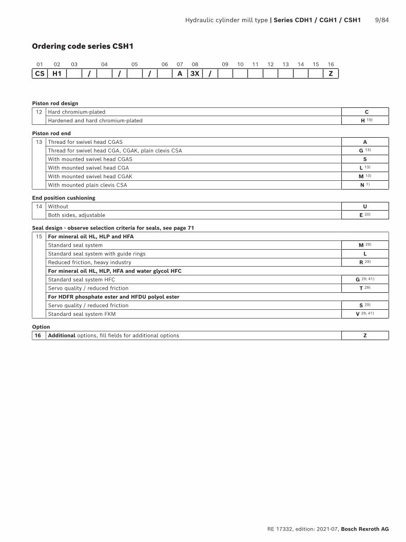
Ordering code series CSH1
01 Differential cylinder with position measurement system CS 18)
02 Series H1
Types of mounting
03 Swivel eye at base MP3 1)
Self-aligning clevis at base MP5
Round flange at head MF3
Round flange at base MF4
Trunnion mounting MT4 2)
Foot mounting MS2
04 Piston Ø (ØAL) 40 … 320 mm
05 Piston rod Ø (ØMM) 28 … 220 mm
06 Stroke length in mm 3)
07 Design principle: Head and base flanged A
08 Component series 30 … 39 (30 … 39: unchanged installation and connection dimensions) 3X
Line connection / version
09 According to ISO 1179-1 (pipe thread ISO 228-1) B
According to ISO 9974-1 (metric thread ISO 261) M
Flange hole pattern according to ISO 6162-2 tab. 2 type 1 (≙SAE 6000 PSI) D 4); 9)
Flange hole pattern according to ISO 6164 tab. 2 H 4)
According to ISO 1179-1 (pipe thread ISO 228-1) with flat pipe flange C 31)
With mounted control block Y 38)
– For directional and control valves
Subplate NG6 P 4); 5)
Subplate NG10 T 4); 6)
Subplate NG16 U 4); 7)
Subplate NG25 V 4); 8)
– For SL and SV valves
Subplate NG6 A 4); 5); 15)
Subplate NG10 E 4); 6); 15)
Subplate NG20 L 4); 7); 15)
Subplate NG30 N 4); 8); 15)
Line connection / position at head
10 View to piston rod 30) 1
2
3
4
Line connection/position at base
11 View to piston rod 30) 1
2 34)
3
4 34)
01 02 03 04 05 06 07 08 09 10 11 12 13 14 15 16
CS H1 / / / A 3X /
Hydraulic cylinder mill type | Series CDH1 / CGH1 / CSH1 9/84
RE 17332, edition: 2021-07, Bosch Rexroth AG
Ordering code series CSH1
Piston rod design
12 Hard chromium-plated C
Hardened and hard chromium-plated H 19)
Piston rod end
13 Thread for swivel head CGAS A
Thread for swivel head CGA, CGAK, plain clevis CSA G 13)
With mounted swivel head CGAS S
With mounted swivel head CGA L 13)
With mounted swivel head CGAK M 13)
With mounted plain clevis CSA N 1)
End position cushioning
14 Without U
Both sides, adjustable E 20)
Seal design - observe selection criteria for seals, see page 71
15 For mineral oil HL, HLP and HFA
Standard seal system M 29)
Standard seal system with guide rings L
Reduced friction, heavy industry R 29)
For mineral oil HL, HLP, HFA and water glycol HFC
Standard seal system HFC G 29; 41)
Servo quality / reduced friction T 29)
For HDFR phosphate ester and HFDU polyol ester
Servo quality / reduced friction S 29)
Standard seal system FKM V 29; 41)
Option
16 Additional options, fill fields for additional options Z
01 02 03 04 05 06 07 08 09 10 11 12 13 14 15 16
CS H1 / / / A 3X / Z

10/84 Series CDH1 /CGH1 / CSH1 | Hydraulic cylinder mill type
Bosch Rexroth AG, RE 17332, edition: 2021-07
Ordering code series CSH1 (fields for additional options)
01 02 03 04 05 06 07 08
Z T
01 Position measurement system (magnetostrictive) without mating connector - separate order, see page 53, 55, 56 and 58
T
02 Analog output 4 … 20 mA C
Analog output 0 … 10 V F
Digital output SSI (resolution 5 µm, asynchronious forward) D
Digital output SSI (resolution 1 µm, synchronious forward) S
Profibus D63 (integrated supply) N
Profibus D53 (separate supply line) P
IO-Link L 39); 40)
Profinet RT and IRT with encoder profile R
03 Without measuring coupling W
Measuring coupling, on both sides A
Measuring coupling, on both sides, stainless steel version E 38)
04 Standard grease nipples, DIN 71412 form A W
Spherical bearing, maintenance-free A 14); 35)
Flat type grease nipples, DIN 3404 form A B
05 Without piston rod extension W
Specify the piston rod extension LY in the plain text in mm Y
06 Priming class CP3 W
Painting class CP4 B 21)
Painting class CP5 L 21)
Painting class CP6 U 21)
Painting class CP7 E 21)
07 Without oil filling W
With corrosion protection oil VG 68 F
08 Without test certificate W
With certificate of compliance 2.1 based on EN 10204 B
With acceptance test certificate 3.1 based on EN 10204 C
Order examples:
With additional options: CSH1MP5/100/56/300A3X/T11CAEMZTCAWWWWW1) Only piston Ø 40 to 200 mm2) Trunnion position freely selectable. When ordering, always specify
the "XV" dimensions in the plain text in mm3) Observe the max. available stroke length page 14 and admissible
stroke length (acc. to buckling calculation) page 65 to 674) Not possible with MF45) Piston Ø 40 to 80 mm, only position 11, subplates only possible
in combination with line connection "B" at the head6) Piston Ø 63 to 200 mm, only position 11, subplates only possible
in combination with line connection "B" at the head7) Piston Ø 125 to 200 mm, only position 11, subplates only
possible in combination with line connection "B" at the head8) Piston Ø 160 to 200 mm, only position 11, subplates only
possible in combination with line connection "B" at the head9) Only piston Ø 80 to 320 mm13) Not with piston Ø 320 mm14) Not possible with plain clevis "N"
15) Subplates for SL and SV valves (check valves) Please note: Seal designs T, G, L, R, S and V are not designed for static hold function!
18) Not standardized19) Only piston rod Ø 28 to 140 mm20) Possible from piston rod Ø 45 mm21) Specify RAL color in the plain text29) With CSH, by default with guide rings30) All graphical pictures in the data sheet show position 131) With MS2, only position 11 is possible34) With MF4 and line connection B, M or C not possible35) Not possible with MP338) On request39) Not possible with MP3 and MP540) Observe min. stroke length 50 mm / max. stroke length 2540 mm41) Not with piston rod Ø 220 mm
Hydraulic cylinder mill type | Series CDH1 / CGH1 / CSH1 11/84
RE 17332, edition: 2021-07, Bosch Rexroth AG
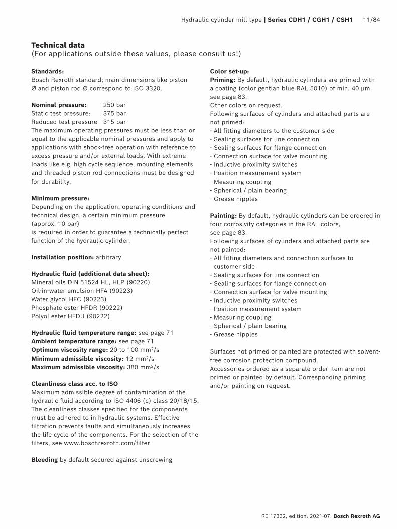
Standards: Bosch Rexroth standard; main dimensions like piston Ø and piston rod Ø correspond to ISO 3320.
Nominal pressure: 250 barStatic test pressure: 375 bar Reduced test pressure 315 bar The maximum operating pressures must be less than or equal to the applicable nominal pressures and apply to applications with shock-free operation with reference to excess pressure and/or external loads. With extreme loads like e.g. high cycle sequence, mounting elements and threaded piston rod connections must be designed for durability.
Minimum pressure: Depending on the application, operating conditions and technical design, a certain minimum pressure (approx. 10 bar) is required in order to guarantee a technically perfect function of the hydraulic cylinder.
Installation position: arbitrary
Hydraulic fluid (additional data sheet): Mineral oils DIN 51524 HL, HLP (90220) Oil-in-water emulsion HFA (90223)Water glycol HFC (90223) Phosphate ester HFDR (90222) Polyol ester HFDU (90222)
Hydraulic fluid temperature range: see page 71 Ambient temperature range: see page 71Optimum viscosity range: 20 to 100 mm2/sMinimum admissible viscosity: 12 mm2/sMaximum admissible viscosity: 380 mm2/s
Cleanliness class acc. to ISO Maximum admissible degree of contamination of the hydraulic fluid according to ISO 4406 (c) class 20/18/15. The cleanliness classes specified for the components must be adhered to in hydraulic systems. Effective filtration prevents faults and simultaneously increases the life cycle of the components. For the selection of the filters, see www.boschrexroth.com/filter
Bleeding by default secured against unscrewing
Color set-up:Priming: By default, hydraulic cylinders are primed with a coating (color gentian blue RAL 5010) of min. 40 μm, see page 83. Other colors on request. Following surfaces of cylinders and attached parts are not primed: - All fitting diameters to the customer side - Sealing surfaces for line connection - Sealing surfaces for flange connection - Connection surface for valve mounting- Inductive proximity switches - Position measurement system - Measuring coupling - Spherical / plain bearing - Grease nipples
Painting: By default, hydraulic cylinders can be ordered in four corrosivity categories in the RAL colors, see page 83. Following surfaces of cylinders and attached parts are not painted:- All fitting diameters and connection surfaces to customer side
- Sealing surfaces for line connection - Sealing surfaces for flange connection - Connection surface for valve mounting - Inductive proximity switches - Position measurement system - Measuring coupling - Spherical / plain bearing - Grease nipples
Surfaces not primed or painted are protected with solvent-free corrosion protection compound.Accessories ordered as a separate order item are not primed or painted by default. Corresponding priming and/or painting on request.
Technical data (For applications outside these values, please consult us!)

12/84 Series CDH1 /CGH1 / CSH1 | Hydraulic cylinder mill type
Bosch Rexroth AG, RE 17332, edition: 2021-07
Piston Ø (mm) Line connection Max. stroke velocity in m/s
40 G1/2 0.31
50 G1/2 0.20
63 G3/4 0.28
80 G3/4 0.18
100 G1 0.20
125 G1 1/4 0.20
140 G1 1/4 0.16
160 G1 1/2 0.18
180 G1 1/2 0.14
200 G1 1/2 0.11
220 G1 1/2 0.09
250 G1 1/2 0.07
280 G1 1/2 0.06
320 G1 1/2 0.04
Technical data (For applications outside these values, please consult us!)
Stroke velocity:Please observe the guideline on max. stroke velocities (with recommended flow velocity of 5 m/s in the line connection) in the table. Higher stroke velocity on request.If the extension velocity is considerably higher than the retraction velocity of the piston rod, drag-out losses of the medium may result. If necessary, please consult us.
Boundary and application conditions: The mechanical alignment of the movement axis and
thus the mounting points of hydraulic cylinder and piston rod must be ensured. Lateral forces on the guides of piston rod and piston are to be avoided. It may be necessary to consider the own weight of the hydraulic cylinder (MP3 / MP5 or MT4) or the piston rod.
The bending length/bending load of the piston rod and/or the hydraulic cylinder must be observed (see page topic Bucklig).
The maximum admissible stroke velocities with regard to the suitability/load of seals must be observed as must their compatibility with the properties of the hydraulic fluid (see page topic Seals).
The maximum admissible velocities/kinetic energies when moving into the end positions, also considering external loads, must be observed. Danger: Excess pressure
The maximum admissible operating pressure must be complied with in any operating state of the hydraulic cylinder. Possible pressure intensification resulting from the area ratio of annulus area to piston area and possible throttling points are to be observed.
Detrimental environmental influences, like e.g. aggressive finest particles, vapors, high temperatures, etc. as well as contaminations and deterioration of the hydraulic fluid are to be avoided.
Notice: This list does not claim to be complete. In case of
questions regarding the compatibility with the medium or exceedance of the boundary or application conditions, please contact us.
All graphical pictures in the data sheet are examples. The product supplied may therefore differ from the figure shown.
Hydraulic cylinder mill type | Series CDH1 / CGH1 / CSH1 13/84
RE 17332, edition: 2021-07, Bosch Rexroth AG
Technical data (For applications outside these values, please consult us!)
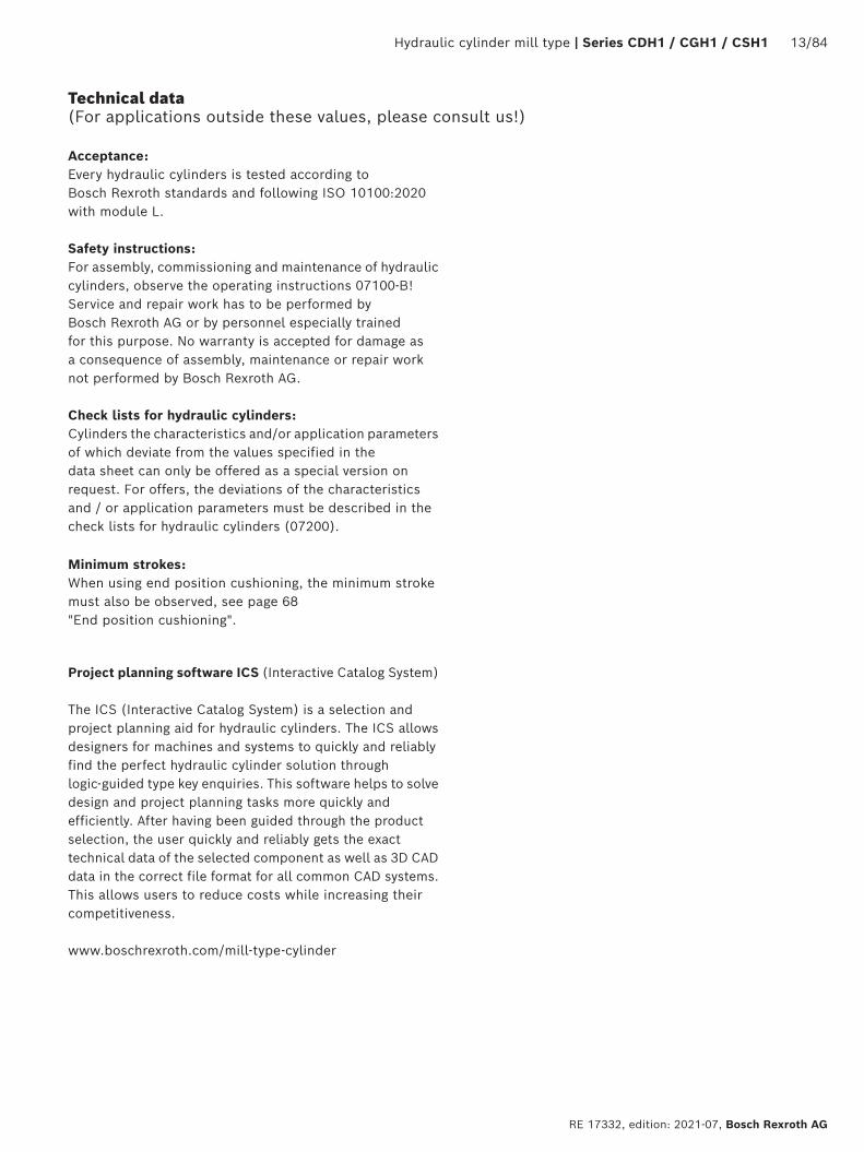
Acceptance: Every hydraulic cylinders is tested according to Bosch Rexroth standards and following ISO 10100:2020 with module L.
Safety instructions: For assembly, commissioning and maintenance of hydraulic cylinders, observe the operating instructions 07100-B! Service and repair work has to be performed by Bosch Rexroth AG or by personnel especially trained for this purpose. No warranty is accepted for damage as a consequence of assembly, maintenance or repair work not performed by Bosch Rexroth AG.
Check lists for hydraulic cylinders: Cylinders the characteristics and/or application parameters of which deviate from the values specified in the data sheet can only be offered as a special version on request. For offers, the deviations of the characteristics and / or application parameters must be described in the check lists for hydraulic cylinders (07200).
Minimum strokes: When using end position cushioning, the minimum stroke must also be observed, see page 68 "End position cushioning".
Project planning software ICS (Interactive Catalog System)
The ICS (Interactive Catalog System) is a selection and project planning aid for hydraulic cylinders. The ICS allows designers for machines and systems to quickly and reliably find the perfect hydraulic cylinder solution through logic-guided type key enquiries. This software helps to solve design and project planning tasks more quickly and
efficiently. After having been guided through the product selection, the user quickly and reliably gets the exact technical data of the selected component as well as 3D CAD data in the correct file format for all common CAD systems.This allows users to reduce costs while increasing their competitiveness.
www.boschrexroth.com/mill-type-cylinder
14/84 Series CDH1 /CGH1 / CSH1 | Hydraulic cylinder mill type
Bosch Rexroth AG, RE 17332, edition: 2021-07
Technical data (For applications outside these values, please consult us!)
Piston Piston rod
Area ratio
Areas Force at 250 bar 1) Flow at 0.1 m/s 2) Max. available stroke length
Piston Rod Ring Pressure Diff. Pulling Off Diff. On
ØALmm
ØMMmm
ϕA1/A3
A1
cm2
A2
cm2
A3
cm2
F1
kNF2
kNF3
kNqV1
l/minqV2
l/minqV3
l/minmm
4022 28
1.43 1.96
12.563.80 6.16
8.76 6.40
31.409.50 15.40
21.90 16.00
7.52.3 3.7
5.3 3.8
2000
5028 36
1.46 2.08
19.636.16 10.18
13.47 9.45
49.1015.40 25.45
33.70 23.65
11.83.7 6.1
8.1 5.7
2000
6336 45
1.48 2.04
31.1710.18 15.90
20.99 15.27
77.9025.45 39.75
52.45 38.15
18.76.1 9.5
12.6 9.2
2000
8045 56
1.46 1.96
50.2615.90 24.63
34.36 25.63
125.6539.75 61.55
85.90 64.10
30.29.5 14.8
20.7 15.4
2000
10056 70
1.46 1.96
78.5424.63 38.48
53.91 40.06
196.3561.55 96.20
134.80 100.15
47.114.8 23.1
32.3 24.0
3000
12570 90
1.46 2.08
122.7238.48 63.62
84.24 59.10
306.7596.20 159.05
210.55 147.70
73.623.1 38.2
50.5 35.4
3000
14090 100
1.70 2.04
153.9463.62 78.54
90.32 75.40
384.75159.05 196.35
225.70 188.40
92.438.2 47.1
54.2 45.3
3000
160100 110
1.64 1.90
201.0678.54 95.06
122.50 106.00
502.50196.35 237.65
306.15 264.85
120.647.1 57.0
73.5 63.6
3000
180110 125
1.60 1.93
254.4795.06 122.72
159.43 131.75
636.17237.65 306.80
398.52 329.37
152.757.0 73.6
95.7 79.1
3000
200125 140
1.64 1.96
314.16122.72 153.96
191.44 160.20
785.25306.80 384.90
478.45 400.35
188.573.6 92.4
114.9 96.1
3000
220140 160
1.68 2.12
380.1153.9 201.0
226.2 179.1
950.3384.8 502.6
565.5 447.7
228.192.4 120.7
135.7 107.4
6000
250160 180
1.69 2.08
490.8201.0 254.4
289.8 236.4
1227.2502.7 636.2
724.5 591.0
294.5120.7 152.7
173.8 141.8
6000
280180 200
1.70 2.04
615.7254.4 314.1
361.3 301.6
1539.4636.2 785.4
903.2 753.9
369.4152.7 188.5
216.7 180.9
6000
320200 220
1.64 1.90
804.2314.1 380.1
490.1 424.2
2010.6785.4 950.3
1225.2 1060.3
482.5188.5 228.1
294.0 254.4
6000
1) Theoretical static cylinder force (without consideration of the efficiency and admissible load for attachment parts such as swivel heads, plates, or valves, etc.)
2) Stroke velocity
Diameters, areas, forces, flow

Hydraulic cylinder mill type | Series CDH1 / CGH1 / CSH1 15/84
RE 17332, edition: 2021-07, Bosch Rexroth AG
Tolerances according to DIN ISO 6022
Installation dimensions WC XC 2) XO 2) XS 1; 2) XV 2) ZP 2)
Stroke tolerances 3)
Type of mounting MF3 MP3 MP5 MS2 MT4 MF4
Stroke length Tolerances
≤ 1250 ±2 ±1.5 ±1.5 ±2 ±2 ±1.5 +2
> 1250 – ≤ 3150 ±4 ±3 ±3 ±4 ±4 ±3 +5
> 3150 – ≤ 6000 ±8 ±5 ±5 ±8 ±8 ±5 +8
1) Not standardized2) Including stroke length3) Stroke tolerances must not be added to the tolerances listed
in this table.
Technical data (For applications outside these values, please consult us!)

16/84 Series CDH1 /CGH1 / CSH1 | Hydraulic cylinder mill type
Bosch Rexroth AG, RE 17332, edition: 2021-07
CDH1 MP3; see page 18, 19
CDH1 MP5; see page 20, 21
CDH1 MF3; see page 22, 23 CGH1 MF3; see page 22, 23
CDH1 MF4; see page 24, 25
CDH1 MT4; see page 26, 27 CGH1 MT4; see page 26, 27
CDH1 MS2; see page 28, 29 CGH1 MS2; see page 28, 29
Overview types of mounting: Series CDH1 / CGH1

Hydraulic cylinder mill type | Series CDH1 / CGH1 / CSH1 17/84
RE 17332, edition: 2021-07, Bosch Rexroth AG
CSH1 MP3 CSH1 MF4see page 30, 31 see page 36, 37
CSH1 MP5 CSH1 MT4see page 32, 33 see page 38, 39
CSH1 MF3 CSH1 MS2see page 34, 35 see page 40, 41
Overview types of mounting: Series CSH1

18/84 Series CDH1 /CGH1 / CSH1 | Hydraulic cylinder mill type
Bosch Rexroth AG, RE 17332, edition: 2021-07
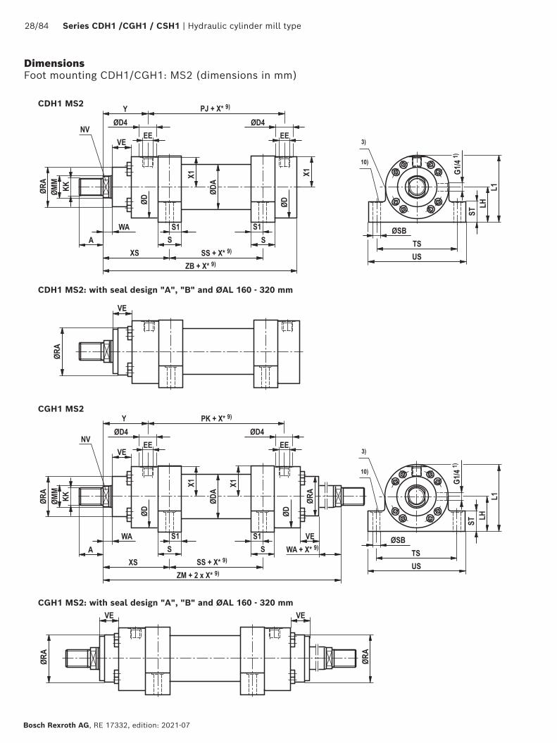
Dimensions Swivel eye at base CDH1: MP3 (dimensions in mm)
CDH1 MP3; ØAL 40 - 200 mm
CDH1 MP3: with seal design "A", "B" and ØAL 160 - 200 mm
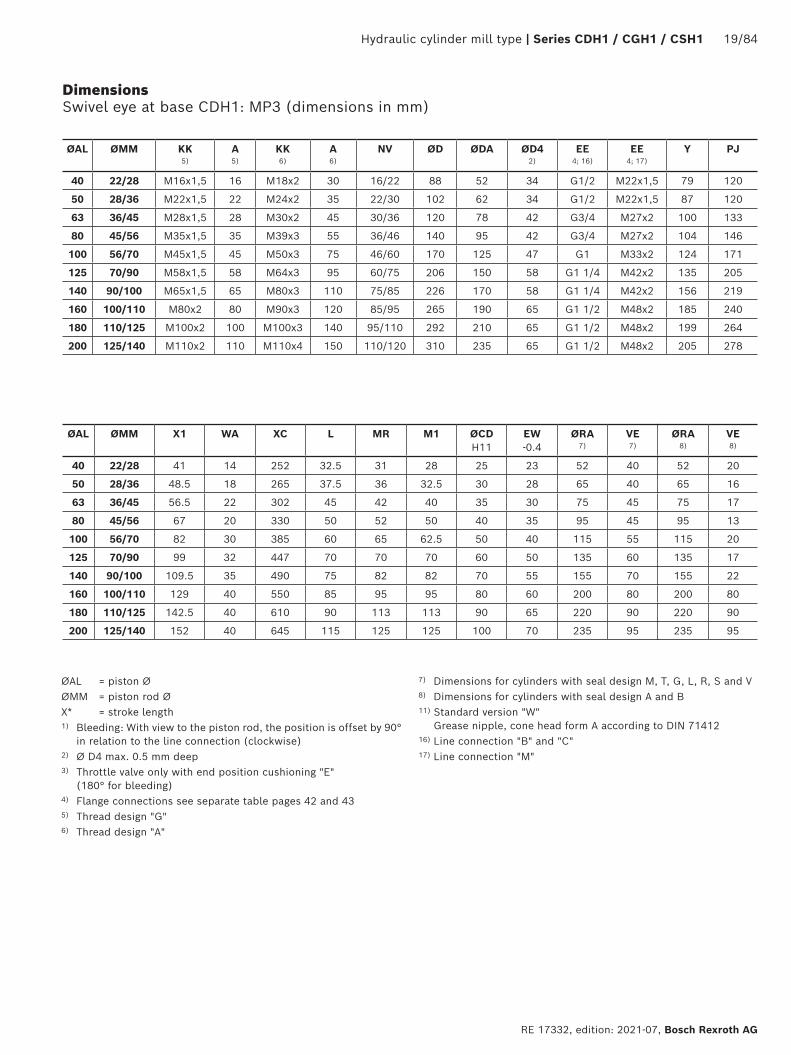
Hydraulic cylinder mill type | Series CDH1 / CGH1 / CSH1 19/84
RE 17332, edition: 2021-07, Bosch Rexroth AG
ØAL ØMM KK 5)
A 5)
KK 6)
A 6)
NV ØD ØDA ØD4 2)
EE 4; 16)
EE 4; 17)
Y PJ
40 22/28 M16x1,5 16 M18x2 30 16/22 88 52 34 G1/2 M22x1,5 79 120
50 28/36 M22x1,5 22 M24x2 35 22/30 102 62 34 G1/2 M22x1,5 87 120
63 36/45 M28x1,5 28 M30x2 45 30/36 120 78 42 G3/4 M27x2 100 133
80 45/56 M35x1,5 35 M39x3 55 36/46 140 95 42 G3/4 M27x2 104 146
100 56/70 M45x1,5 45 M50x3 75 46/60 170 125 47 G1 M33x2 124 171
125 70/90 M58x1,5 58 M64x3 95 60/75 206 150 58 G1 1/4 M42x2 135 205
140 90/100 M65x1,5 65 M80x3 110 75/85 226 170 58 G1 1/4 M42x2 156 219
160 100/110 M80x2 80 M90x3 120 85/95 265 190 65 G1 1/2 M48x2 185 240
180 110/125 M100x2 100 M100x3 140 95/110 292 210 65 G1 1/2 M48x2 199 264
200 125/140 M110x2 110 M110x4 150 110/120 310 235 65 G1 1/2 M48x2 205 278
ØAL ØMM X1 WA XC L MR M1 ØCD H11
EW -0.4
ØRA 7)
VE 7)
ØRA 8)
VE 8)
40 22/28 41 14 252 32.5 31 28 25 23 52 40 52 20
50 28/36 48.5 18 265 37.5 36 32.5 30 28 65 40 65 16
63 36/45 56.5 22 302 45 42 40 35 30 75 45 75 17
80 45/56 67 20 330 50 52 50 40 35 95 45 95 13
100 56/70 82 30 385 60 65 62.5 50 40 115 55 115 20
125 70/90 99 32 447 70 70 70 60 50 135 60 135 17
140 90/100 109.5 35 490 75 82 82 70 55 155 70 155 22
160 100/110 129 40 550 85 95 95 80 60 200 80 200 80
180 110/125 142.5 40 610 90 113 113 90 65 220 90 220 90
200 125/140 152 40 645 115 125 125 100 70 235 95 235 95
ØAL = piston ØØMM = piston rod ØX* = stroke length1) Bleeding: With view to the piston rod, the position is offset by 90°
in relation to the line connection (clockwise)2) Ø D4 max. 0.5 mm deep3) Throttle valve only with end position cushioning "E"
(180° for bleeding)4) Flange connections see separate table pages 42 and 435) Thread design "G"6) Thread design "A"
7) Dimensions for cylinders with seal design M, T, G, L, R, S and V8) Dimensions for cylinders with seal design A and B11) Standard version "W"
Grease nipple, cone head form A according to DIN 7141216) Line connection "B" and "C"17) Line connection "M"
Dimensions Swivel eye at base CDH1: MP3 (dimensions in mm)
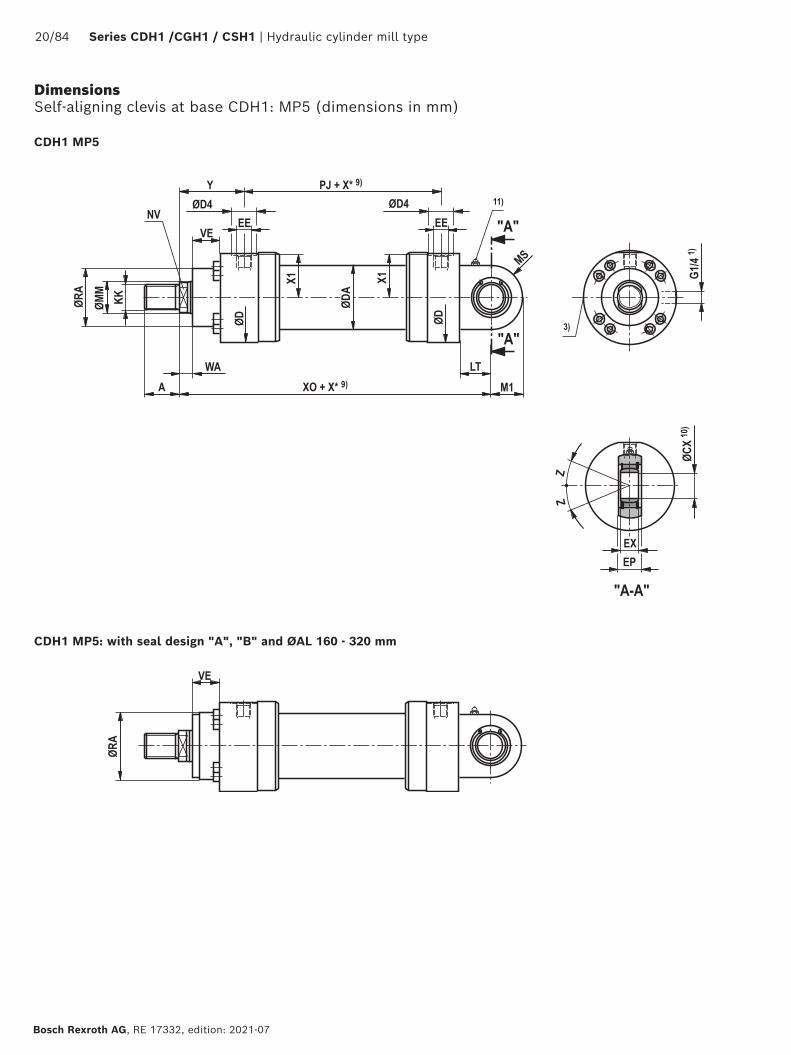
20/84 Series CDH1 /CGH1 / CSH1 | Hydraulic cylinder mill type
Bosch Rexroth AG, RE 17332, edition: 2021-07
Dimensions Self-aligning clevis at base CDH1: MP5 (dimensions in mm)
CDH1 MP5: with seal design "A", "B" and ØAL 160 - 320 mm
CDH1 MP5
Hydraulic cylinder mill type | Series CDH1 / CGH1 / CSH1 21/84
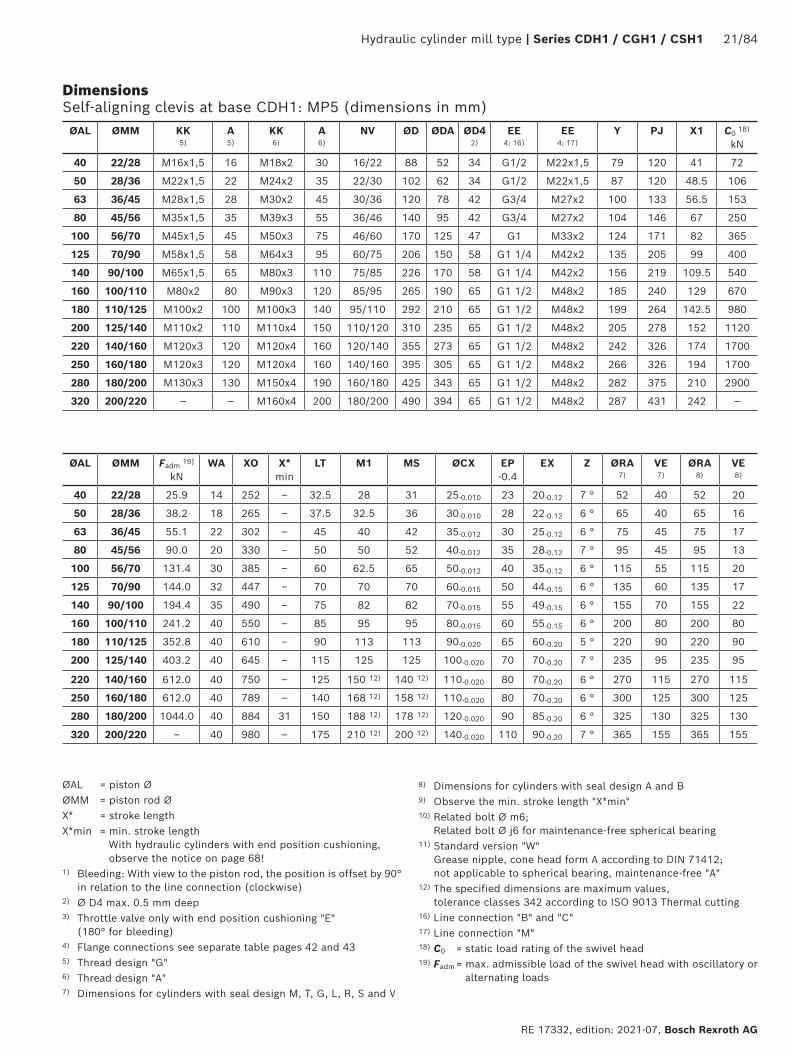
RE 17332, edition: 2021-07, Bosch Rexroth AG
ØAL ØMM KK 5)
A 5)
KK 6)
A 6)
NV ØD ØDA ØD4 2)
EE 4; 16)
EE 4; 17)
Y PJ X1 C0 18)
kN
40 22/28 M16x1,5 16 M18x2 30 16/22 88 52 34 G1/2 M22x1,5 79 120 41 72
50 28/36 M22x1,5 22 M24x2 35 22/30 102 62 34 G1/2 M22x1,5 87 120 48.5 106
63 36/45 M28x1,5 28 M30x2 45 30/36 120 78 42 G3/4 M27x2 100 133 56.5 153
80 45/56 M35x1,5 35 M39x3 55 36/46 140 95 42 G3/4 M27x2 104 146 67 250
100 56/70 M45x1,5 45 M50x3 75 46/60 170 125 47 G1 M33x2 124 171 82 365
125 70/90 M58x1,5 58 M64x3 95 60/75 206 150 58 G1 1/4 M42x2 135 205 99 400
140 90/100 M65x1,5 65 M80x3 110 75/85 226 170 58 G1 1/4 M42x2 156 219 109.5 540
160 100/110 M80x2 80 M90x3 120 85/95 265 190 65 G1 1/2 M48x2 185 240 129 670
180 110/125 M100x2 100 M100x3 140 95/110 292 210 65 G1 1/2 M48x2 199 264 142.5 980
200 125/140 M110x2 110 M110x4 150 110/120 310 235 65 G1 1/2 M48x2 205 278 152 1120
220 140/160 M120x3 120 M120x4 160 120/140 355 273 65 G1 1/2 M48x2 242 326 174 1700
250 160/180 M120x3 120 M120x4 160 140/160 395 305 65 G1 1/2 M48x2 266 326 194 1700
280 180/200 M130x3 130 M150x4 190 160/180 425 343 65 G1 1/2 M48x2 282 375 210 2900
320 200/220 – – M160x4 200 180/200 490 394 65 G1 1/2 M48x2 287 431 242 –
ØAL ØAL ØMM ØMM FFadm adm 19)19)
kNkNWAWA XOXO X* X*
minminLTLT M1M1 MSMS ØCXØCX EP EP
-0.4-0.4EXEX ZZ ØRA ØRA
7)7)VE VE 7)7)
ØRA ØRA 8)8)
VE VE 8)8)
40 22/28 25.9 14 252 – 32.5 28 31 25-0.010 23 20-0.12 7 ° 52 40 52 20
50 28/36 38.2 18 265 – 37.5 32.5 36 30-0.010 28 22-0.12 6 ° 65 40 65 16
63 36/45 55.1 22 302 – 45 40 42 35-0.012 30 25-0.12 6 ° 75 45 75 17
80 45/56 90.0 20 330 – 50 50 52 40-0.012 35 28-0.12 7 ° 95 45 95 13
100 56/70 131.4 30 385 – 60 62.5 65 50-0.012 40 35-0.12 6 ° 115 55 115 20
125 70/90 144.0 32 447 – 70 70 70 60-0.015 50 44-0.15 6 ° 135 60 135 17
140 90/100 194.4 35 490 – 75 82 82 70-0.015 55 49-0.15 6 ° 155 70 155 22
160 100/110 241.2 40 550 – 85 95 95 80-0.015 60 55-0.15 6 ° 200 80 200 80
180 110/125 352.8 40 610 – 90 113 113 90-0.020 65 60-0.20 5 ° 220 90 220 90
200 125/140 403.2 40 645 – 115 125 125 100-0.020 70 70-0.20 7 ° 235 95 235 95
220 140/160 612.0 40 750 – 125 150 12) 140 12) 110-0.020 80 70-0.20 6 ° 270 115 270 115
250 160/180 612.0 40 789 – 140 168 12) 158 12) 110-0.020 80 70-0.20 6 ° 300 125 300 125
280 180/200 1044.0 40 884 31 150 188 12) 178 12) 120-0.020 90 85-0.20 6 ° 325 130 325 130
320 200/220 – 40 980 – 175 210 12) 200 12) 140-0.020 110 90-0.20 7 ° 365 155 365 155
ØAL = piston ØØMM = piston rod ØX* = stroke lengthX*min = min. stroke length
With hydraulic cylinders with end position cushioning, observe the notice on page 68!
1) Bleeding: With view to the piston rod, the position is offset by 90° in relation to the line connection (clockwise)
2) Ø D4 max. 0.5 mm deep3) Throttle valve only with end position cushioning "E"
(180° for bleeding)4) Flange connections see separate table pages 42 and 435) Thread design "G"6) Thread design "A"7) Dimensions for cylinders with seal design M, T, G, L, R, S and V
8) Dimensions for cylinders with seal design A and B9) Observe the min. stroke length "X*min"10) Related bolt Ø m6;
Related bolt Ø j6 for maintenance-free spherical bearing11) Standard version "W"
Grease nipple, cone head form A according to DIN 71412; not applicable to spherical bearing, maintenance-free "A"
12) The specified dimensions are maximum values, tolerance classes 342 according to ISO 9013 Thermal cutting
16) Line connection "B" and "C"17) Line connection "M" 18) C0 = static load rating of the swivel head19) Fadm = max. admissible load of the swivel head with oscillatory or
alternating loads
Dimensions Self-aligning clevis at base CDH1: MP5 (dimensions in mm)

22/84 Series CDH1 /CGH1 / CSH1 | Hydraulic cylinder mill type
Bosch Rexroth AG, RE 17332, edition: 2021-07
CDH1 MF3
CGH1 MF3: with seal design "A", "B" and ØAL 160 - 320 mm
CGH1 MF3
Dimensions Round flange at head CDH1/CGH1: MF3 (dimensions in mm)
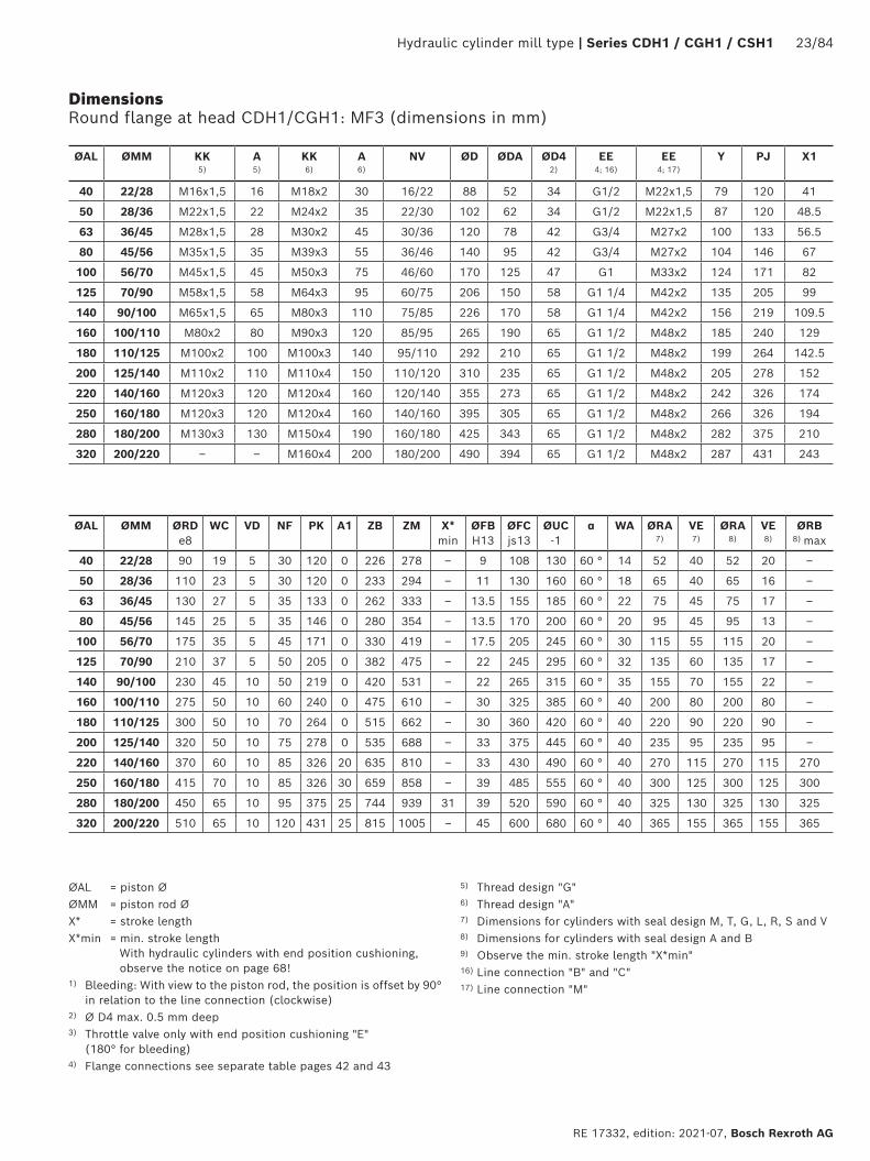
Hydraulic cylinder mill type | Series CDH1 / CGH1 / CSH1 23/84
RE 17332, edition: 2021-07, Bosch Rexroth AG
ØAL ØMM KK 5)
A 5)
KK 6)
A 6)
NV ØD ØDA ØD4 2)
EE 4; 16)
EE 4; 17)
Y PJ X1
40 22/28 M16x1,5 16 M18x2 30 16/22 88 52 34 G1/2 M22x1,5 79 120 41
50 28/36 M22x1,5 22 M24x2 35 22/30 102 62 34 G1/2 M22x1,5 87 120 48.5
63 36/45 M28x1,5 28 M30x2 45 30/36 120 78 42 G3/4 M27x2 100 133 56.5
80 45/56 M35x1,5 35 M39x3 55 36/46 140 95 42 G3/4 M27x2 104 146 67
100 56/70 M45x1,5 45 M50x3 75 46/60 170 125 47 G1 M33x2 124 171 82
125 70/90 M58x1,5 58 M64x3 95 60/75 206 150 58 G1 1/4 M42x2 135 205 99
140 90/100 M65x1,5 65 M80x3 110 75/85 226 170 58 G1 1/4 M42x2 156 219 109.5
160 100/110 M80x2 80 M90x3 120 85/95 265 190 65 G1 1/2 M48x2 185 240 129
180 110/125 M100x2 100 M100x3 140 95/110 292 210 65 G1 1/2 M48x2 199 264 142.5
200 125/140 M110x2 110 M110x4 150 110/120 310 235 65 G1 1/2 M48x2 205 278 152
220 140/160 M120x3 120 M120x4 160 120/140 355 273 65 G1 1/2 M48x2 242 326 174
250 160/180 M120x3 120 M120x4 160 140/160 395 305 65 G1 1/2 M48x2 266 326 194
280 180/200 M130x3 130 M150x4 190 160/180 425 343 65 G1 1/2 M48x2 282 375 210
320 200/220 – – M160x4 200 180/200 490 394 65 G1 1/2 M48x2 287 431 243
ØAL ØMM ØRD e8
WC VD NF PK A1 ZB ZM X* min
ØFB H13
ØFC js13
ØUC -1
α WA ØRA 7)
VE 7)
ØRA 8)
VE 8)
ØRB
8) max
40 22/28 90 19 5 30 120 0 226 278 – 9 108 130 60 ° 14 52 40 52 20 –
50 28/36 110 23 5 30 120 0 233 294 – 11 130 160 60 ° 18 65 40 65 16 –
63 36/45 130 27 5 35 133 0 262 333 – 13.5 155 185 60 ° 22 75 45 75 17 –
80 45/56 145 25 5 35 146 0 280 354 – 13.5 170 200 60 ° 20 95 45 95 13 –
100 56/70 175 35 5 45 171 0 330 419 – 17.5 205 245 60 ° 30 115 55 115 20 –
125 70/90 210 37 5 50 205 0 382 475 – 22 245 295 60 ° 32 135 60 135 17 –
140 90/100 230 45 10 50 219 0 420 531 – 22 265 315 60 ° 35 155 70 155 22 –
160 100/110 275 50 10 60 240 0 475 610 – 30 325 385 60 ° 40 200 80 200 80 –
180 110/125 300 50 10 70 264 0 515 662 – 30 360 420 60 ° 40 220 90 220 90 –
200 125/140 320 50 10 75 278 0 535 688 – 33 375 445 60 ° 40 235 95 235 95 –
220 140/160 370 60 10 85 326 20 635 810 – 33 430 490 60 ° 40 270 115 270 115 270
250 160/180 415 70 10 85 326 30 659 858 – 39 485 555 60 ° 40 300 125 300 125 300
280 180/200 450 65 10 95 375 25 744 939 31 39 520 590 60 ° 40 325 130 325 130 325
320 200/220 510 65 10 120 431 25 815 1005 – 45 600 680 60 ° 40 365 155 365 155 365
ØAL = piston ØØMM = piston rod ØX* = stroke lengthX*min = min. stroke length
With hydraulic cylinders with end position cushioning, observe the notice on page 68!
1) Bleeding: With view to the piston rod, the position is offset by 90° in relation to the line connection (clockwise)
2) Ø D4 max. 0.5 mm deep3) Throttle valve only with end position cushioning "E"
(180° for bleeding)4) Flange connections see separate table pages 42 and 43
5) Thread design "G"6) Thread design "A"7) Dimensions for cylinders with seal design M, T, G, L, R, S and V8) Dimensions for cylinders with seal design A and B9) Observe the min. stroke length "X*min"16) Line connection "B" and "C"17) Line connection "M"
Dimensions Round flange at head CDH1/CGH1: MF3 (dimensions in mm)

24/84 Series CDH1 /CGH1 / CSH1 | Hydraulic cylinder mill type
Bosch Rexroth AG, RE 17332, edition: 2021-07
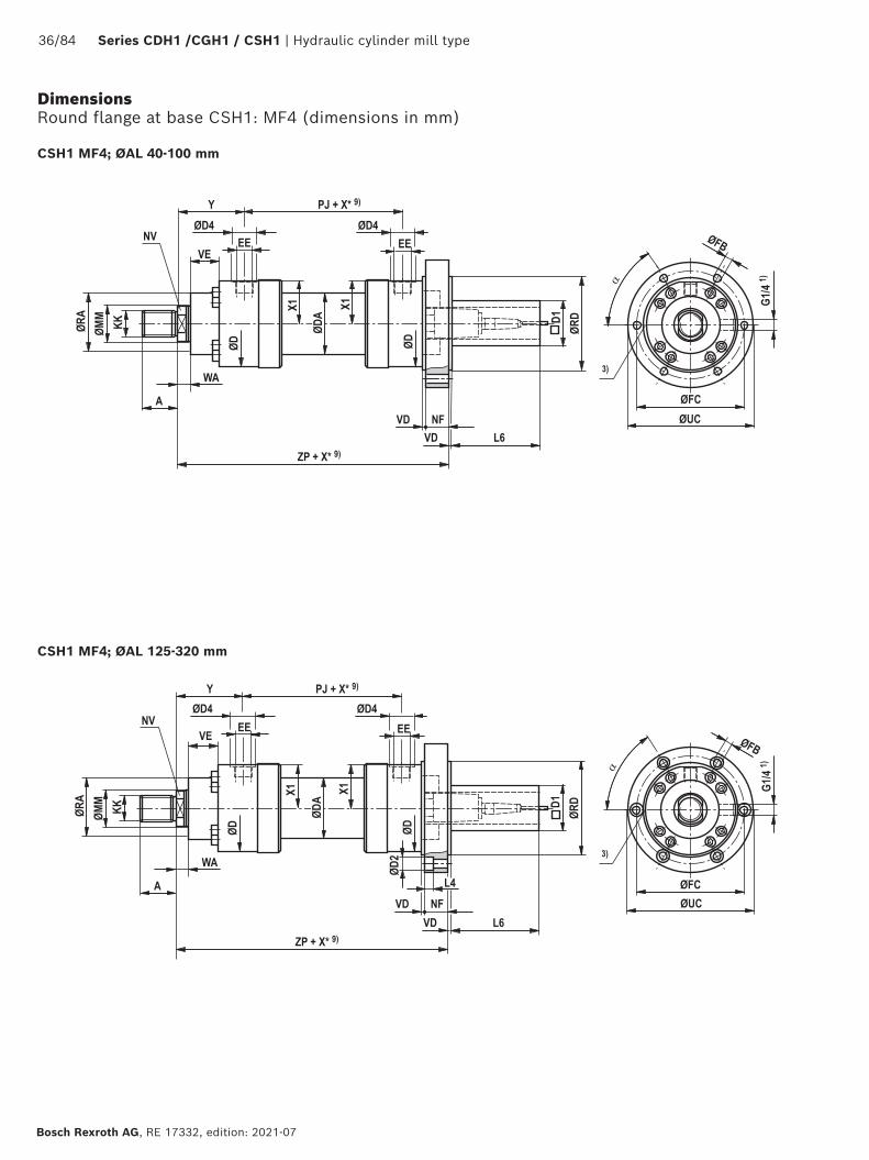
CDH1 MF4: with seal design "A", "B" and ØAL 160 - 320 mm
Dimensions Round flange at base CDH1: MF4 (dimensions in mm)
CDH1 MF4

Hydraulic cylinder mill type | Series CDH1 / CGH1 / CSH1 25/84
RE 17332, edition: 2021-07, Bosch Rexroth AG
ØAL ØMM KK 5)
A 5)
KK 6)
A 6)
NV ØD ØDA ØD4 2)
EE 4; 16)
EE 4; 17)
Y PJ X1
40 22/28 M16x1,5 16 M18x2 30 16/22 88 52 34 G1/2 M22x1,5 79 120 41
50 28/36 M22x1,5 22 M24x2 35 22/30 102 62 34 G1/2 M22x1,5 87 120 48.5
63 36/45 M28x1,5 28 M30x2 45 30/36 120 78 42 G3/4 M27x2 100 133 56.5
80 45/56 M35x1,5 35 M39x3 55 36/46 140 95 42 G3/4 M27x2 104 146 67
100 56/70 M45x1,5 45 M50x3 75 46/60 170 125 47 G1 M33x2 124 171 82
125 70/90 M58x1,5 58 M64x3 95 60/75 206 150 58 G1 1/4 M42x2 135 205 99
140 90/100 M65x1,5 65 M80x3 110 75/85 226 170 58 G1 1/4 M42x2 156 219 109.5
160 100/110 M80x2 80 M90x3 120 85/95 265 190 65 G1 1/2 M48x2 185 240 129
180 110/125 M100x2 100 M100x3 140 95/110 292 210 65 G1 1/2 M48x2 199 264 142.5
200 125/140 M110x2 110 M110x4 150 110/120 310 235 65 G1 1/2 M48x2 205 278 152
220 140/160 M120x3 120 M120x4 160 120/140 355 273 65 G1 1/2 M48x2 242 326 174
250 160/180 M120x3 120 M120x4 160 140/160 395 305 65 G1 1/2 M48x2 266 326 194
280 180/200 M130x3 130 M150x4 190 160/180 425 343 65 G1 1/2 M48x2 282 375 210
320 200/220 – – M160x4 200 180/200 490 394 65 G1 1/2 M48x2 287 431 243
ØAL ØMM WA ZP X* min
NF VD ØRD e8
ØFB H13
ØFC js13
ØUC -1
α ØRA 7)
VE 7)
ØRA 8)
VE 8)
40 22/28 14 256 – 30 5 90 9 108 130 60 ° 52 40 52 20
50 28/36 18 264 – 30 5 110 11 130 160 60 ° 65 40 65 16
63 36/45 22 297 – 35 5 130 13.5 155 185 60 ° 75 45 75 17
80 45/56 20 315 – 35 5 145 13.5 170 200 60 ° 95 45 95 13
100 56/70 30 375 – 45 5 175 17.5 205 245 60 ° 115 55 115 20
125 70/90 32 432 – 50 5 210 22 245 295 60 ° 135 60 135 17
140 90/100 35 475 – 50 10 230 22 265 315 60 ° 155 70 155 22
160 100/110 40 535 – 60 10 275 30 325 385 60 ° 200 80 200 80
180 110/125 40 585 – 70 10 300 30 360 420 60 ° 220 90 220 90
200 125/140 40 615 – 75 10 320 33 375 445 60 ° 235 95 235 95
220 140/160 40 720 – 85 10 370 33 430 490 60 ° 270 115 270 115
250 160/180 40 744 – 85 10 415 39 485 555 60 ° 300 125 300 125
280 180/200 40 839 31 95 10 450 39 520 590 60 ° 325 130 325 130
320 200/220 40 935 – 120 10 510 45 600 680 60 ° 365 155 365 155
ØAL = piston ØØMM = piston rod ØX* = stroke lengthX*min = min. stroke length
With hydraulic cylinders with end position cushioning,observe the notice on page 68!
1) Bleeding: With view to the piston rod, the position is offset by 90° in relation to the line connection (clockwise)
2) Ø D4 max. 0.5 mm deep3) Throttle valve only with end position cushioning "E"
(180° for bleeding)
4) Flange connections see separate table pages 42 and 435) Thread design "G"6) Thread design "A"7) Dimensions for cylinders with seal design M, T, G, L, R, S and V8) Dimensions for cylinders with seal design A and B9) Observe the min. stroke length "X*min"16) Line connection "B" and "C"17) Line connection "M"
Dimensions Round flange at base CDH1: MF4 (dimensions in mm)
26/84 Series CDH1 /CGH1 / CSH1 | Hydraulic cylinder mill type
Bosch Rexroth AG, RE 17332, edition: 2021-07
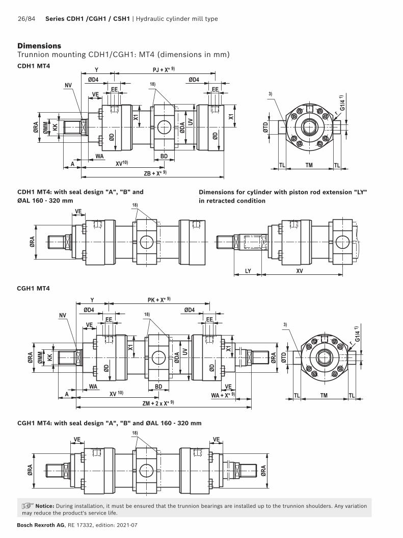
Dimensions Trunnion mounting CDH1/CGH1: MT4 (dimensions in mm)
CGH1 MT4: with seal design "A", "B" and ØAL 160 - 320 mm
CGH1 MT4
CDH1 MT4: with seal design "A", "B" and ØAL 160 - 320 mm
Dimensions for cylinder with piston rod extension "LY" in retracted condition
CDH1 MT4
Notice: During installation, it must be ensured that the trunnion bearings are installed up to the trunnion shoulders. Any variation may reduce the product's service life.

Hydraulic cylinder mill type | Series CDH1 / CGH1 / CSH1 27/84
RE 17332, edition: 2021-07, Bosch Rexroth AG
ØAL ØMM PK ZB ZM X* min
XV
11) centXV
10) minXV
10) maxBD UV
12)ØTD e8
TL js16
TM h12
r ØRA 7)
VE 7)
ØRA 8)
VE 8)
40 22/28 120 226 278 22 139+X*/2 150 136+X* 38 97 30 20 95 1.6 52 40 52 20
50 28/36 120 233 294 32 147+X*/2 163 140+X* 38 111 30 20 115 1.6 65 40 65 16
63 36/45 133 262 333 47 166.5+X*/2 190 155+X* 48 129 35 20 130 2 75 45 75 17
80 45/56 146 280 354 58 177+X*/2 206 160+X* 58 153 40 25 145 2 95 45 95 13
100 56/70 171 330 419 79 209.5+X*/2 249 185+X* 78 183 50 30 175 2 115 55 115 20
125 70/90 205 382 475 91 237.5+X*/2 283 192+X* 98 220 60 40 210 2.5 135 60 135 17
140 90/100 219 420 531 121 265.5+X*/2 326 205+X* 118 243 65 42.5 230 2.5 155 70 155 22
160 100/110 240 475 610 142 305+X*/2 376 234+X* 128 282 75 52.5 275 2.5 200 80 200 80
180 110/125 264 515 661 158 331+X*/2 410 252+X* 138 310 85 55 300 2.5 220 90 220 90
200 125/140 278 535 688 194 344+X*/2 441 247+X* 168 331 90 55 320 2.5 235 95 235 95
220 140/160 326 635 810 155 405+X*/2 482.5 327.5+X* 135 377 100 60 370 2.5 270 115 270 115
250 160/180 326 659 858 175 429+X*/2 516.5 341.5+X* 145 417 110 65 410 2.5 300 125 300 125
280 180/200 375 744 939 336 469.5+X*/2 637.5 301.5+X* 165 448 130 70 450 2.5 325 130 325 130
320 200/220 431 815 1005 180 502.5+X*/2 592.5 412.5+X* 195 513 160 90 510 2.5 365 155 365 155
ØAL ØMM KK 5)
A 5)
KK 6)
A 6)
NV ØD ØDA ØD4 2)
EE 4; 16)
EE 4; 17)
Y PJ X1 WA
40 22/28 M16x1,5 16 M18x2 30 16/22 88 52 34 G1/2 M22x1,5 79 120 41 14
50 28/36 M22x1,5 22 M24x2 35 22/30 102 62 34 G1/2 M22x1,5 87 120 48.5 18
63 36/45 M28x1,5 28 M30x2 45 30/36 120 78 42 G3/4 M27x2 100 133 56.5 22
80 45/56 M35x1,5 35 M39x3 55 36/46 140 95 42 G3/4 M27x2 104 146 67 20
100 56/70 M45x1,5 45 M50x3 75 46/60 170 125 47 G1 M33x2 124 171 82 30
125 70/90 M58x1,5 58 M64x3 95 60/75 206 150 58 G1 1/4 M42x2 135 205 99 32
140 90/100 M65x1,5 65 M80x3 110 75/85 226 170 58 G1 1/4 M42x2 156 219 109.5 35
160 100/110 M80x2 80 M90x3 120 85/95 265 190 65 G1 1/2 M48x2 185 240 129 40
180 110/125 M100x2 100 M100x3 140 95/110 292 210 65 G1 1/2 M48x2 199 264 142.5 40
200 125/140 M110x2 110 M110x4 150 110/120 310 235 65 G1 1/2 M48x2 205 278 152 40
220 140/160 M120x3 120 M120x4 160 120/140 355 273 65 G1 1/2 M48x2 242 326 174 40
250 160/180 M120x3 120 M120x4 160 140/160 395 305 65 G1 1/2 M48x2 266 326 194 40
280 180/200 M130x3 130 M150x4 190 160/180 425 343 65 G1 1/2 M48x2 282 375 210 40
320 200/220 – – M160x4 200 180/200 490 394 65 G1 1/2 M48x2 287 431 243 40
ØAL = piston ØØMM = piston rod ØX* = stroke lengthX*min = min. stroke length
With hydraulic cylinders with end position cushioning, observe the notice on page 68!
1) Bleeding: With view to the piston rod, the position is offset by 90° in relation to the line connection (clockwise)
2) Ø D4 max. 0.5 mm deep3) Throttle valve only with end position cushioning "E"
(180° for bleeding)4) Flange connections see separate table pages 42 and 435) Thread design "G"6) Thread design "A"
7) Dimensions for cylinders with seal design M, T, G, L, R, S, V8) Dimensions for cylinders with seal design A and B9) Observe the min. stroke length "X*min"10) When ordering, always specify the "XV" dimension in the clear text.
Preferred XV dimension: Observe the trunnion position in the cylinder center XVmin and XVmax
11) XVcent recommendation: Trunnion position in cylinder center
12) The specified dimensions are maximum values, tolerance classes 342 according to ISO 9013 Thermal cutting
16) Line connection "B" and "C"17) Line connection "M" 18) Trunnion nut with ØAL ≥ 125 mm either at head or at base side
depending on the position of the trunnion (XV)
Dimensions Trunnion mountings CDH1/CGH1: MT4 (dimensions in mm)
28/84 Series CDH1 /CGH1 / CSH1 | Hydraulic cylinder mill type
Bosch Rexroth AG, RE 17332, edition: 2021-07
Dimensions Foot mounting CDH1/CGH1: MS2 (dimensions in mm)
CGH1 MS2: with seal design "A", "B" and ØAL 160 - 320 mm
CDH1 MS2: with seal design "A", "B" and ØAL 160 - 320 mm
CDH1 MS2
CGH1 MS2
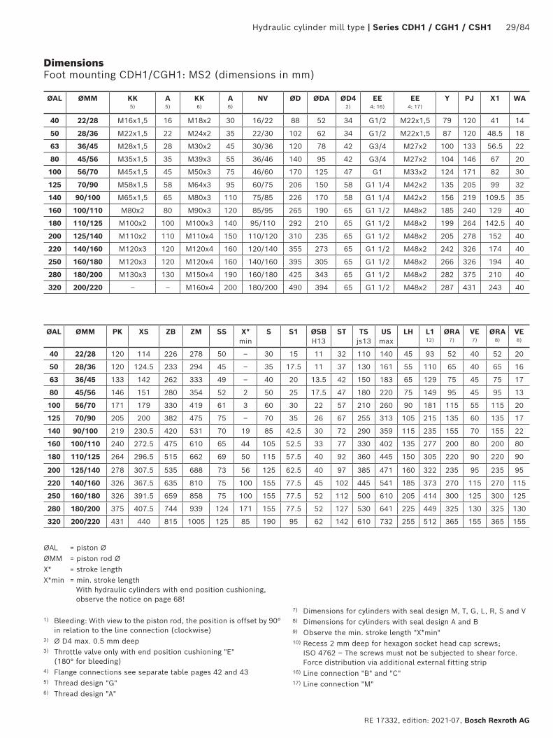
Hydraulic cylinder mill type | Series CDH1 / CGH1 / CSH1 29/84
RE 17332, edition: 2021-07, Bosch Rexroth AG
ØAL ØMM KK 5)
A 5)
KK 6)
A 6)
NV ØD ØDA ØD4 2)
EE 4; 16)
EE 4; 17)
Y PJ X1 WA
40 22/28 M16x1,5 16 M18x2 30 16/22 88 52 34 G1/2 M22x1,5 79 120 41 14
50 28/36 M22x1,5 22 M24x2 35 22/30 102 62 34 G1/2 M22x1,5 87 120 48.5 18
63 36/45 M28x1,5 28 M30x2 45 30/36 120 78 42 G3/4 M27x2 100 133 56.5 22
80 45/56 M35x1,5 35 M39x3 55 36/46 140 95 42 G3/4 M27x2 104 146 67 20
100 56/70 M45x1,5 45 M50x3 75 46/60 170 125 47 G1 M33x2 124 171 82 30
125 70/90 M58x1,5 58 M64x3 95 60/75 206 150 58 G1 1/4 M42x2 135 205 99 32
140 90/100 M65x1,5 65 M80x3 110 75/85 226 170 58 G1 1/4 M42x2 156 219 109.5 35
160 100/110 M80x2 80 M90x3 120 85/95 265 190 65 G1 1/2 M48x2 185 240 129 40
180 110/125 M100x2 100 M100x3 140 95/110 292 210 65 G1 1/2 M48x2 199 264 142.5 40
200 125/140 M110x2 110 M110x4 150 110/120 310 235 65 G1 1/2 M48x2 205 278 152 40
220 140/160 M120x3 120 M120x4 160 120/140 355 273 65 G1 1/2 M48x2 242 326 174 40
250 160/180 M120x3 120 M120x4 160 140/160 395 305 65 G1 1/2 M48x2 266 326 194 40
280 180/200 M130x3 130 M150x4 190 160/180 425 343 65 G1 1/2 M48x2 282 375 210 40
320 200/220 – – M160x4 200 180/200 490 394 65 G1 1/2 M48x2 287 431 243 40
ØAL ØMM PK XS ZB ZM SS X* min
S S1 ØSB H13
ST TS js13
US max
LH L1 12)
ØRA 7)
VE 7)
ØRA 8)
VE 8)
40 22/28 120 114 226 278 50 – 30 15 11 32 110 140 45 93 52 40 52 20
50 28/36 120 124.5 233 294 45 – 35 17.5 11 37 130 161 55 110 65 40 65 16
63 36/45 133 142 262 333 49 – 40 20 13.5 42 150 183 65 129 75 45 75 17
80 45/56 146 151 280 354 52 2 50 25 17.5 47 180 220 75 149 95 45 95 13
100 56/70 171 179 330 419 61 3 60 30 22 57 210 260 90 181 115 55 115 20
125 70/90 205 200 382 475 75 – 70 35 26 67 255 313 105 215 135 60 135 17
140 90/100 219 230.5 420 531 70 19 85 42.5 30 72 290 359 115 235 155 70 155 22
160 100/110 240 272.5 475 610 65 44 105 52.5 33 77 330 402 135 277 200 80 200 80
180 110/125 264 296.5 515 662 69 50 115 57.5 40 92 360 445 150 305 220 90 220 90
200 125/140 278 307.5 535 688 73 56 125 62.5 40 97 385 471 160 322 235 95 235 95
220 140/160 326 367.5 635 810 75 100 155 77.5 45 102 445 541 185 373 270 115 270 115
250 160/180 326 391.5 659 858 75 100 155 77.5 52 112 500 610 205 414 300 125 300 125
280 180/200 375 407.5 744 939 124 171 155 77.5 52 127 530 641 225 449 325 130 325 130
320 200/220 431 440 815 1005 125 85 190 95 62 142 610 732 255 512 365 155 365 155
ØAL = piston ØØMM = piston rod ØX* = stroke lengthX*min = min. stroke length
With hydraulic cylinders with end position cushioning, observe the notice on page 68!
1) Bleeding: With view to the piston rod, the position is offset by 90° in relation to the line connection (clockwise)
2) Ø D4 max. 0.5 mm deep3) Throttle valve only with end position cushioning "E"
(180° for bleeding)4) Flange connections see separate table pages 42 and 435) Thread design "G"6) Thread design "A"
7) Dimensions for cylinders with seal design M, T, G, L, R, S and V8) Dimensions for cylinders with seal design A and B9) Observe the min. stroke length "X*min"10) Recess 2 mm deep for hexagon socket head cap screws;
ISO 4762 – The screws must not be subjected to shear force. Force distribution via additional external fitting strip
16) Line connection "B" and "C"17) Line connection "M"
Dimensions Foot mounting CDH1/CGH1: MS2 (dimensions in mm)
30/84 Series CDH1 /CGH1 / CSH1 | Hydraulic cylinder mill type
Bosch Rexroth AG, RE 17332, edition: 2021-07
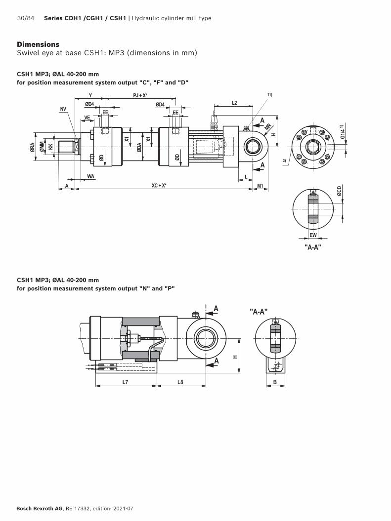
Dimensions Swivel eye at base CSH1: MP3 (dimensions in mm)
CSH1 MP3; ØAL 40-200 mmfor position measurement system output "C", "F" and "D"
CSH1 MP3; ØAL 40-200 mmfor position measurement system output "N" and "P"
Hydraulic cylinder mill type | Series CDH1 / CGH1 / CSH1 31/84
RE 17332, edition: 2021-07, Bosch Rexroth AG
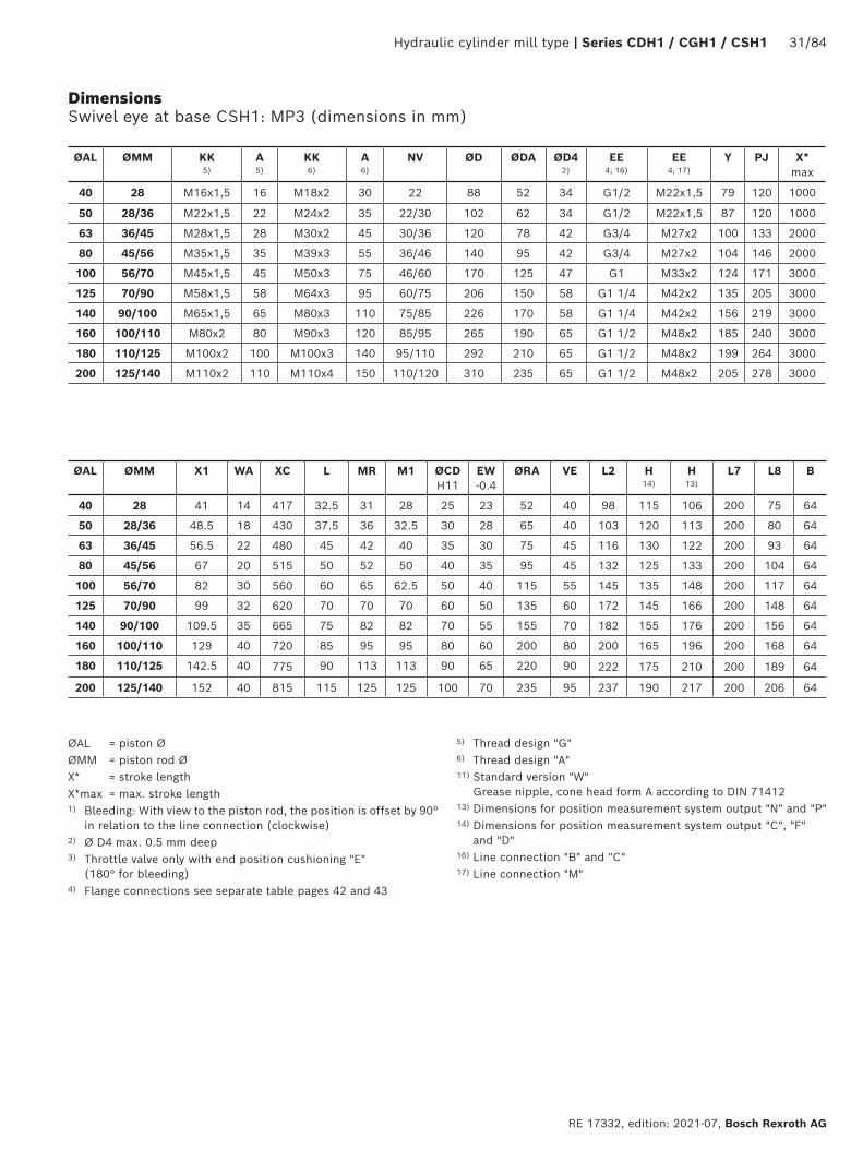
Dimensions Swivel eye at base CSH1: MP3 (dimensions in mm)
ØAL ØMM KK 5)
A 5)
KK 6)
A 6)
NV ØD ØDA ØD4 2)
EE 4; 16)
EE 4; 17)
Y PJ X* max
40 28 M16x1,5 16 M18x2 30 22 88 52 34 G1/2 M22x1,5 79 120 1000
50 28/36 M22x1,5 22 M24x2 35 22/30 102 62 34 G1/2 M22x1,5 87 120 1000
63 36/45 M28x1,5 28 M30x2 45 30/36 120 78 42 G3/4 M27x2 100 133 2000
80 45/56 M35x1,5 35 M39x3 55 36/46 140 95 42 G3/4 M27x2 104 146 2000
100 56/70 M45x1,5 45 M50x3 75 46/60 170 125 47 G1 M33x2 124 171 3000
125 70/90 M58x1,5 58 M64x3 95 60/75 206 150 58 G1 1/4 M42x2 135 205 3000
140 90/100 M65x1,5 65 M80x3 110 75/85 226 170 58 G1 1/4 M42x2 156 219 3000
160 100/110 M80x2 80 M90x3 120 85/95 265 190 65 G1 1/2 M48x2 185 240 3000
180 110/125 M100x2 100 M100x3 140 95/110 292 210 65 G1 1/2 M48x2 199 264 3000
200 125/140 M110x2 110 M110x4 150 110/120 310 235 65 G1 1/2 M48x2 205 278 3000
ØAL ØMM X1 WA XC L MR M1 ØCD H11
EW -0.4
ØRA VE L2 H 14)
H 13)
L7 L8 B
40 28 41 14 417 32.5 31 28 25 23 52 40 98 115 106 200 75 64
50 28/36 48.5 18 430 37.5 36 32.5 30 28 65 40 103 120 113 200 80 64
63 36/45 56.5 22 480 45 42 40 35 30 75 45 116 130 122 200 93 64
80 45/56 67 20 515 50 52 50 40 35 95 45 132 125 133 200 104 64
100 56/70 82 30 560 60 65 62.5 50 40 115 55 145 135 148 200 117 64
125 70/90 99 32 620 70 70 70 60 50 135 60 172 145 166 200 148 64
140 90/100 109.5 35 665 75 82 82 70 55 155 70 182 155 176 200 156 64
160 100/110 129 40 720 85 95 95 80 60 200 80 200 165 196 200 168 64
180 110/125 142.5 40 775 90 113 113 90 65 220 90 222 175 210 200 189 64
200 125/140 152 40 815 115 125 125 100 70 235 95 237 190 217 200 206 64
ØAL = piston ØØMM = piston rod ØX* = stroke lengthX*max = max. stroke length1) Bleeding: With view to the piston rod, the position is offset by 90°
in relation to the line connection (clockwise)2) Ø D4 max. 0.5 mm deep3) Throttle valve only with end position cushioning "E"
(180° for bleeding)4) Flange connections see separate table pages 42 and 43
5) Thread design "G"6) Thread design "A"11) Standard version "W"
Grease nipple, cone head form A according to DIN 7141213) Dimensions for position measurement system output "N" and "P"14) Dimensions for position measurement system output "C", "F"
and "D"16) Line connection "B" and "C"17) Line connection "M"
32/84 Series CDH1 /CGH1 / CSH1 | Hydraulic cylinder mill type
Bosch Rexroth AG, RE 17332, edition: 2021-07
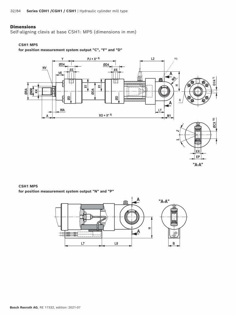
Dimensions Self-aligning clevis at base CSH1: MP5 (dimensions in mm)
CSH1 MP5for position measurement system output "C", "F" and "D"
CSH1 MP5for position measurement system output "N" and "P"

Hydraulic cylinder mill type | Series CDH1 / CGH1 / CSH1 33/84
RE 17332, edition: 2021-07, Bosch Rexroth AG
Dimensions Self-aligning clevis at base CSH1: MP5 (dimensions in mm)
ØAL ØMM KK 5)
A 5)
KK 6)
A 6)
NV ØD ØDA ØD4 2)
EE 4; 16)
EE 4; 17)
Y PJ X1 X* max
C0 18)
kN
40 28 M16x1,5 16 M18x2 30 22 88 52 34 G1/2 M22x1,5 79 120 41 1000 72
50 28/36 M22x1,5 22 M24x2 35 22/30 102 62 34 G1/2 M22x1,5 87 120 48.5 1000 106
63 36/45 M28x1,5 28 M30x2 45 30/36 120 78 42 G3/4 M27x2 100 133 56.5 2000 153
80 45/56 M35x1,5 35 M39x3 55 36/46 140 95 42 G3/4 M27x2 104 146 67 2000 250
100 56/70 M45x1,5 45 M50x3 75 46/60 170 125 47 G1 M33x2 124 171 82 3000 365
125 70/90 M58x1,5 58 M64x3 95 60/75 206 150 58 G1 1/4 M42x2 135 205 99 3000 400
140 90/100 M65x1,5 65 M80x3 110 75/85 226 170 58 G1 1/4 M42x2 156 219 109.5 3000 540
160 100/110 M80x2 80 M90x3 120 85/95 265 190 65 G1 1/2 M48x2 185 240 129 3000 670
180 110/125 M100x2 100 M100x3 140 95/110 292 210 65 G1 1/2 M48x2 199 264 142.5 3000 980
200 125/140 M110x2 110 M110x4 150 110/120 310 235 65 G1 1/2 M48x2 205 278 152 3000 1120
220 140/160 M120x3 120 M120x4 160 120/140 355 273 65 G1 1/2 M48x2 242 326 174 3000 1700
250 160/180 M120x3 120 M120x4 160 140/160 395 305 65 G1 1/2 M48x2 266 326 194 3000 1700
280 180/200 M130x3 130 M150x4 190 160/180 425 343 65 G1 1/2 M48x2 282 375 210 3000 2900
320 200/220 – – M160x4 200 180/200 490 394 65 G1 1/2 M48x2 287 431 242 3000 –
ØAL ØMM Fadm 19)
kNWA XO X*
minLT M1 MS ØCX EP
-0.4EX Z ØRA VE L2 H
14)H 13)
L7 L8 B
40 28 25.9 14 417 – 32.5 28 31 25-0.010 23 20-0.12 7 ° 52 40 98 115 106 200 75 64
50 28/36 38.2 18 430 – 37.5 32.5 36 30-0.010 28 22-0.12 6 ° 65 40 103 120 113 200 80 64
63 36/45 55.1 22 480 – 45 40 42 35-0.012 30 25-0.12 6 ° 75 45 116 130 122 200 93 64
80 45/56 90.0 20 515 – 50 50 52 40-0.012 35 28-0.12 7 ° 95 45 132 125 133 200 104 64
100 56/70 131.4 30 560 – 60 62.5 65 50-0.012 40 35-0.12 6 ° 115 55 145 135 148 200 117 64
125 70/90 144.0 32 620 – 70 70 70 60-0.015 50 44-0.15 6 ° 135 60 172 145 166 200 148 64
140 90/100 194.4 35 665 – 75 82 82 70-0.015 55 49-0.15 6 ° 155 70 182 155 176 200 156 64
160 100/110 241.2 40 720 – 85 95 95 80-0.015 60 55-0.15 6 ° 200 80 200 165 196 200 168 64
180 110/125 352.8 40 775 – 90 113 113 90-0.020 65 60-0.20 5 ° 220 90 222 175 210 200 189 64
200 125/140 403.2 40 815 – 115 125 125 100-0.020 70 70-0.20 7 ° 235 95 237 190 217 200 206 64
220 140/160 612.0 40 960 – 125 150 12) 140 12) 110-0.020 80 70-0.20 6 ° 270 115 280 205 254 200 248 64
250 160/180 612.0 40 1000 – 140 168 12) 158 12) 110-0.020 80 70-0.20 6 ° 300 125 300 220 269 200 263 64
280 180/200 1044.0 40 1105 31 150 188 12) 178 12) 120-0.020 90 85-0.20 6 ° 325 130 330 270 276 200 295 64
320 200/220 – 40 1210 – 175 210 12) 200 12) 140-0.020 110 90-0.20 7 ° 365 155 375 300 309 200 340 64
ØAL = piston ØØMM = piston rod ØX* = stroke lengthX*max = max. stroke lengthX*min = min. stroke length
With hydraulic cylinders with end position cushioning, observe the notice on page 68!
1) Bleeding: With view to the piston rod, the position is offset by 90° in relation to the line connection (clockwise)
2) Ø D4 max. 0.5 mm deep3) Throttle valve only with end position cushioning "E"
(180° for bleeding)4) Flange connections see separate table pages 42 and 435) Thread design "G"6) Thread design "A"
9) Observe the min. stroke length "X*min"10) Related bolt Ø m6;
Related bolt Ø j6 for maintenance-free spherical bearing11) Standard version "W"
Grease nipple, cone head form A according to DIN 71412; not applicable to spherical bearing, maintenance-free "A"
12) The specified dimensions are maximum values, tolerance classes 342 according to ISO 9013 Thermal cutting
13) Dimensions for position measurement system output "N" and "P"14) Dimensions for position measurement system output "C", "F"
and "D"16) Line connection "B" and "C"17) Line connection "M" 18) C0 = static load rating of the swivel head19) Fadm = max. admissible load of the swivel head with oscillatory or
alternating loads

34/84 Series CDH1 /CGH1 / CSH1 | Hydraulic cylinder mill type
Bosch Rexroth AG, RE 17332, edition: 2021-07
Dimensions Round flange at head CSH1: MF3 (dimensions in mm)
CSH1 MF3
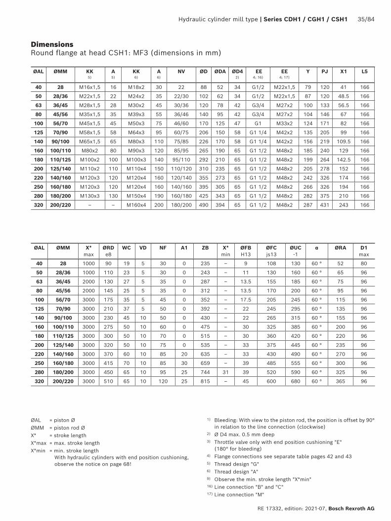
Hydraulic cylinder mill type | Series CDH1 / CGH1 / CSH1 35/84
RE 17332, edition: 2021-07, Bosch Rexroth AG
Dimensions Round flange at head CSH1: MF3 (dimensions in mm)
ØAL ØMM KK 5)
A 5)
KK 6)
A 6)
NV ØD ØDA ØD4 2)
EE 4; 16)
EE 4; 17)
Y PJ X1 L5
40 28 M16x1,5 16 M18x2 30 22 88 52 34 G1/2 M22x1,5 79 120 41 166
50 28/36 M22x1,5 22 M24x2 35 22/30 102 62 34 G1/2 M22x1,5 87 120 48.5 166
63 36/45 M28x1,5 28 M30x2 45 30/36 120 78 42 G3/4 M27x2 100 133 56.5 166
80 45/56 M35x1,5 35 M39x3 55 36/46 140 95 42 G3/4 M27x2 104 146 67 166
100 56/70 M45x1,5 45 M50x3 75 46/60 170 125 47 G1 M33x2 124 171 82 166
125 70/90 M58x1,5 58 M64x3 95 60/75 206 150 58 G1 1/4 M42x2 135 205 99 166
140 90/100 M65x1,5 65 M80x3 110 75/85 226 170 58 G1 1/4 M42x2 156 219 109.5 166
160 100/110 M80x2 80 M90x3 120 85/95 265 190 65 G1 1/2 M48x2 185 240 129 166
180 110/125 M100x2 100 M100x3 140 95/110 292 210 65 G1 1/2 M48x2 199 264 142.5 166
200 125/140 M110x2 110 M110x4 150 110/120 310 235 65 G1 1/2 M48x2 205 278 152 166
220 140/160 M120x3 120 M120x4 160 120/140 355 273 65 G1 1/2 M48x2 242 326 174 166
250 160/180 M120x3 120 M120x4 160 140/160 395 305 65 G1 1/2 M48x2 266 326 194 166
280 180/200 M130x3 130 M150x4 190 160/180 425 343 65 G1 1/2 M48x2 282 375 210 166
320 200/220 – – M160x4 200 180/200 490 394 65 G1 1/2 M48x2 287 431 243 166
ØAL ØMM X* max
ØRD e8
WC VD NF A1 ZB X* min
ØFB H13
ØFC js13
ØUC -1
α ØRA D1 max
40 28 1000 90 19 5 30 0 235 – 9 108 130 60 ° 52 80
50 28/36 1000 110 23 5 30 0 243 – 11 130 160 60 ° 65 96
63 36/45 2000 130 27 5 35 0 287 – 13.5 155 185 60 ° 75 96
80 45/56 2000 145 25 5 35 0 312 – 13.5 170 200 60 ° 95 96
100 56/70 3000 175 35 5 45 0 352 – 17.5 205 245 60 ° 115 96
125 70/90 3000 210 37 5 50 0 392 – 22 245 295 60 ° 135 96
140 90/100 3000 230 45 10 50 0 430 – 22 265 315 60 ° 155 96
160 100/110 3000 275 50 10 60 0 475 – 30 325 385 60 ° 200 96
180 110/125 3000 300 50 10 70 0 515 – 30 360 420 60 ° 220 96
200 125/140 3000 320 50 10 75 0 535 – 33 375 445 60 ° 235 96
220 140/160 3000 370 60 10 85 20 635 – 33 430 490 60 ° 270 96
250 160/180 3000 415 70 10 85 30 659 – 39 485 555 60 ° 300 96
280 180/200 3000 450 65 10 95 25 744 31 39 520 590 60 ° 325 96
320 200/220 3000 510 65 10 120 25 815 – 45 600 680 60 ° 365 96
ØAL = piston ØØMM = piston rod ØX* = stroke lengthX*max = max. stroke lengthX*min = min. stroke length
With hydraulic cylinders with end position cushioning, observe the notice on page 68!
1) Bleeding: With view to the piston rod, the position is offset by 90° in relation to the line connection (clockwise)
2) Ø D4 max. 0.5 mm deep3) Throttle valve only with end position cushioning "E"
(180° for bleeding)4) Flange connections see separate table pages 42 and 435) Thread design "G"6) Thread design "A"9) Observe the min. stroke length "X*min"16) Line connection "B" and "C"17) Line connection "M"
36/84 Series CDH1 /CGH1 / CSH1 | Hydraulic cylinder mill type
Bosch Rexroth AG, RE 17332, edition: 2021-07
Dimensions Round flange at base CSH1: MF4 (dimensions in mm)
CSH1 MF4; ØAL 125-320 mm
CSH1 MF4; ØAL 40-100 mm
Hydraulic cylinder mill type | Series CDH1 / CGH1 / CSH1 37/84
RE 17332, edition: 2021-07, Bosch Rexroth AG
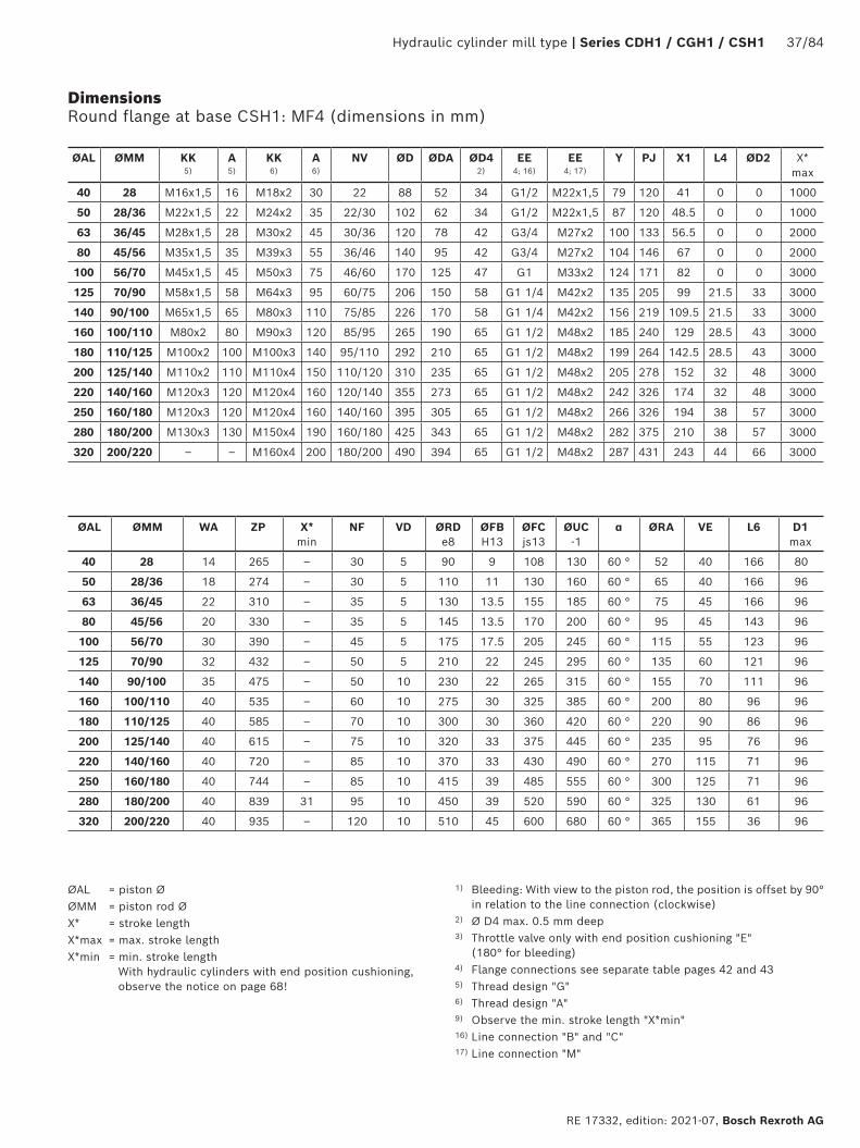
Dimensions Round flange at base CSH1: MF4 (dimensions in mm)
ØAL ØMM KK 5)
A 5)
KK 6)
A 6)
NV ØD ØDA ØD4 2)
EE 4; 16)
EE 4; 17)
Y PJ X1 L4 ØD2 X* max
40 28 M16x1,5 16 M18x2 30 22 88 52 34 G1/2 M22x1,5 79 120 41 0 0 1000
50 28/36 M22x1,5 22 M24x2 35 22/30 102 62 34 G1/2 M22x1,5 87 120 48.5 0 0 1000
63 36/45 M28x1,5 28 M30x2 45 30/36 120 78 42 G3/4 M27x2 100 133 56.5 0 0 2000
80 45/56 M35x1,5 35 M39x3 55 36/46 140 95 42 G3/4 M27x2 104 146 67 0 0 2000
100 56/70 M45x1,5 45 M50x3 75 46/60 170 125 47 G1 M33x2 124 171 82 0 0 3000
125 70/90 M58x1,5 58 M64x3 95 60/75 206 150 58 G1 1/4 M42x2 135 205 99 21.5 33 3000
140 90/100 M65x1,5 65 M80x3 110 75/85 226 170 58 G1 1/4 M42x2 156 219 109.5 21.5 33 3000
160 100/110 M80x2 80 M90x3 120 85/95 265 190 65 G1 1/2 M48x2 185 240 129 28.5 43 3000
180 110/125 M100x2 100 M100x3 140 95/110 292 210 65 G1 1/2 M48x2 199 264 142.5 28.5 43 3000
200 125/140 M110x2 110 M110x4 150 110/120 310 235 65 G1 1/2 M48x2 205 278 152 32 48 3000
220 140/160 M120x3 120 M120x4 160 120/140 355 273 65 G1 1/2 M48x2 242 326 174 32 48 3000
250 160/180 M120x3 120 M120x4 160 140/160 395 305 65 G1 1/2 M48x2 266 326 194 38 57 3000
280 180/200 M130x3 130 M150x4 190 160/180 425 343 65 G1 1/2 M48x2 282 375 210 38 57 3000
320 200/220 – – M160x4 200 180/200 490 394 65 G1 1/2 M48x2 287 431 243 44 66 3000
ØAL ØMM WA ZP X* min
NF VD ØRD e8
ØFB H13
ØFC js13
ØUC -1
α ØRA VE L6 D1 max
40 28 14 265 – 30 5 90 9 108 130 60 ° 52 40 166 80
50 28/36 18 274 – 30 5 110 11 130 160 60 ° 65 40 166 96
63 36/45 22 310 – 35 5 130 13.5 155 185 60 ° 75 45 166 96
80 45/56 20 330 – 35 5 145 13.5 170 200 60 ° 95 45 143 96
100 56/70 30 390 – 45 5 175 17.5 205 245 60 ° 115 55 123 96
125 70/90 32 432 – 50 5 210 22 245 295 60 ° 135 60 121 96
140 90/100 35 475 – 50 10 230 22 265 315 60 ° 155 70 111 96
160 100/110 40 535 – 60 10 275 30 325 385 60 ° 200 80 96 96
180 110/125 40 585 – 70 10 300 30 360 420 60 ° 220 90 86 96
200 125/140 40 615 – 75 10 320 33 375 445 60 ° 235 95 76 96
220 140/160 40 720 – 85 10 370 33 430 490 60 ° 270 115 71 96
250 160/180 40 744 – 85 10 415 39 485 555 60 ° 300 125 71 96
280 180/200 40 839 31 95 10 450 39 520 590 60 ° 325 130 61 96
320 200/220 40 935 – 120 10 510 45 600 680 60 ° 365 155 36 96
ØAL = piston ØØMM = piston rod ØX* = stroke lengthX*max = max. stroke lengthX*min = min. stroke length
With hydraulic cylinders with end position cushioning, observe the notice on page 68!
1) Bleeding: With view to the piston rod, the position is offset by 90° in relation to the line connection (clockwise)
2) Ø D4 max. 0.5 mm deep3) Throttle valve only with end position cushioning "E"
(180° for bleeding)4) Flange connections see separate table pages 42 and 435) Thread design "G"6) Thread design "A"9) Observe the min. stroke length "X*min"16) Line connection "B" and "C"17) Line connection "M"
38/84 Series CDH1 /CGH1 / CSH1 | Hydraulic cylinder mill type
Bosch Rexroth AG, RE 17332, edition: 2021-07
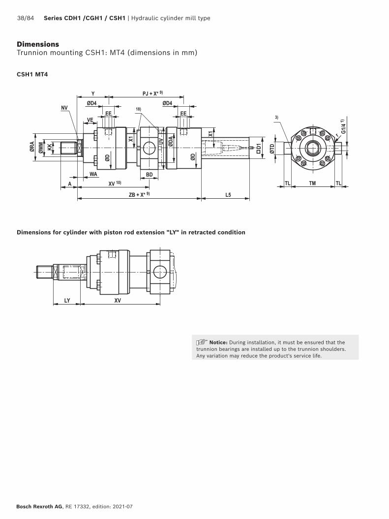
Dimensions Trunnion mounting CSH1: MT4 (dimensions in mm)
Dimensions for cylinder with piston rod extension "LY" in retracted condition
Notice: During installation, it must be ensured that the trunnion bearings are installed up to the trunnion shoulders. Any variation may reduce the product's service life.
CSH1 MT4

Hydraulic cylinder mill type | Series CDH1 / CGH1 / CSH1 39/84
RE 17332, edition: 2021-07, Bosch Rexroth AG
Dimensions Trunnion mounting CSH1: MT4 (dimensions in mm)
ØAL ØMM KK 5)
A 5)
KK 6)
A 6)
NV ØD ØDA ØD4 2)
EE 4; 16)
EE 4; 17)
Y PJ X1 WA L5 X* max
40 28 M16x1,5 16 M18x2 30 22 88 52 34 G1/2 M22x1,5 79 120 41 14 166 1000
50 28/36 M22x1,5 22 M24x2 35 22/30 102 62 34 G1/2 M22x1,5 87 120 48.5 18 166 1000
63 36/45 M28x1,5 28 M30x2 45 30/36 120 78 42 G3/4 M27x2 100 133 56.5 22 166 2000
80 45/56 M35x1,5 35 M39x3 55 36/46 140 95 42 G3/4 M27x2 104 146 67 20 166 2000
100 56/70 M45x1,5 45 M50x3 75 46/60 170 125 47 G1 M33x2 124 171 82 30 166 3000
125 70/90 M58x1,5 58 M64x3 95 60/75 206 150 58 G1 1/4 M42x2 135 205 99 32 166 3000
140 90/100 M65x1,5 65 M80x3 110 75/85 226 170 58 G1 1/4 M42x2 156 219 109.5 35 166 3000
160 100/110 M80x2 80 M90x3 120 85/95 265 190 65 G1 1/2 M48x2 185 240 129 40 166 3000
180 110/125 M100x2 100 M100x3 140 95/110 292 210 65 G1 1/2 M48x2 199 264 142.5 40 166 3000
200 125/140 M110x2 110 M110x4 150 110/120 310 235 65 G1 1/2 M48x2 205 278 152 40 166 3000
220 140/160 M120x3 120 M120x4 160 120/140 355 273 65 G1 1/2 M48x2 242 326 174 40 166 3000
250 160/180 M120x3 120 M120x4 160 140/160 395 305 65 G1 1/2 M48x2 266 326 194 40 166 3000
280 180/200 M130x3 130 M150x4 190 160/180 425 343 65 G1 1/2 M48x2 282 375 210 40 166 3000
320 200/220 – – M160x4 200 180/200 490 394 65 G1 1/2 M48x2 287 431 243 40 166 3000
ØAL ØMM ZB X* min
XV
11) centXV
10) minXV
10) maxBD UV
12)ØTD e8
TL js16
TM h12
r ØRA VE D1 max
40 28 235 22 139+X*/2 150 136+X* 38 97 30 20 95 1.6 52 40 80
50 28/36 243 32 147+X*/2 163 140+X* 38 111 30 20 115 1.6 65 40 96
63 36/45 287 47 166.5+X*/2 190 155+X* 48 129 35 20 130 2 75 45 96
80 45/56 312 58 177+X*/2 206 160+X* 58 153 40 25 145 2 95 45 96
100 56/70 352 79 209.5+X*/2 249 185+X* 78 183 50 30 175 2 115 55 96
125 70/90 392 91 237.5+X*/2 283 192+X* 98 220 60 40 210 2.5 135 60 96
140 90/100 430 121 265.5+X*/2 326 205+X* 118 243 65 42.5 230 2.5 155 70 96
160 100/110 475 142 305+X*/2 376 234+X* 128 282 75 52.5 275 2.5 200 80 96
180 110/125 515 158 331+X*/2 410 252+X* 138 310 85 55 300 2.5 220 90 96
200 125/140 535 194 344+X*/2 441 247+X* 168 331 90 55 320 2.5 235 95 96
220 140/160 635 155 405+X*/2 482.5 327.5+X* 135 377 100 60 370 2.5 270 115 96
250 160/180 659 175 429+X*/2 516.5 341.5+X* 145 417 110 65 410 2.5 300 125 96
280 180/200 744 336 469.5+X*/2 637.5 301.5+X* 165 448 130 70 450 2.5 325 130 96
320 200/220 815 180 502.5+X*/2 592.5 412.5+X* 195 513 160 90 510 2.5 365 155 96
ØAL = piston ØØMM = piston rod ØX* = stroke lengthX*max = max. stroke lengthX*min = min. stroke length
With hydraulic cylinders with end position cushioning, observe the notice on page 68!
1) Bleeding: With view to the piston rod, the position is offset by 90° in relation to the line connection (clockwise)
2) Ø D4 max. 0.5 mm deep3) Throttle valve only with end position cushioning "E"
(180° for bleeding)4) Flange connections see separate table pages 42 and 43
5) Thread design "G"6) Thread design "A"9) Observe the min. stroke length "X*min"10) When ordering, always specify the "XV" dimension in the clear
text. Preferred XV dimension: Observe the trunnion position in the cylinder center XVmin and XVmax
11) XVcent recommendation: Trunnion position in cylinder center12) The specified dimensions are maximum values,
tolerance classes 342 according to ISO 9013 Thermal cutting16) Line connection "B" and "C"17) Line connection "M" 18) Trunnion nut with ØAL ≥ 125 mm either at head or at base side
depending on the position of the trunnion (XV)
40/84 Series CDH1 /CGH1 / CSH1 | Hydraulic cylinder mill type
Bosch Rexroth AG, RE 17332, edition: 2021-07
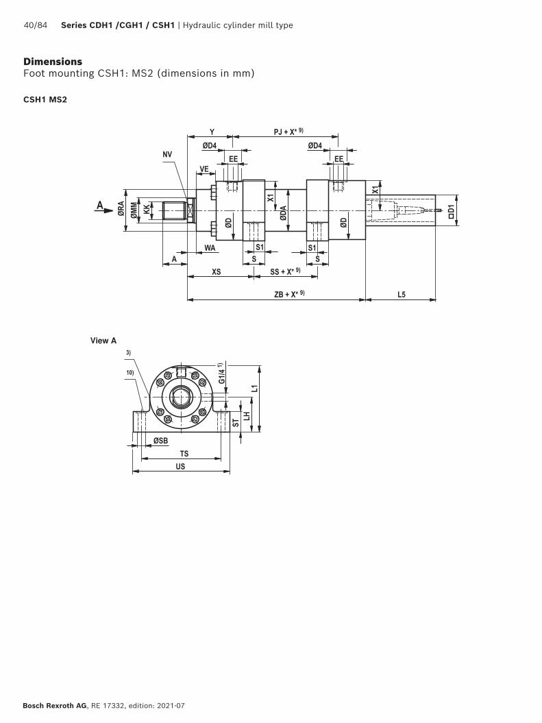
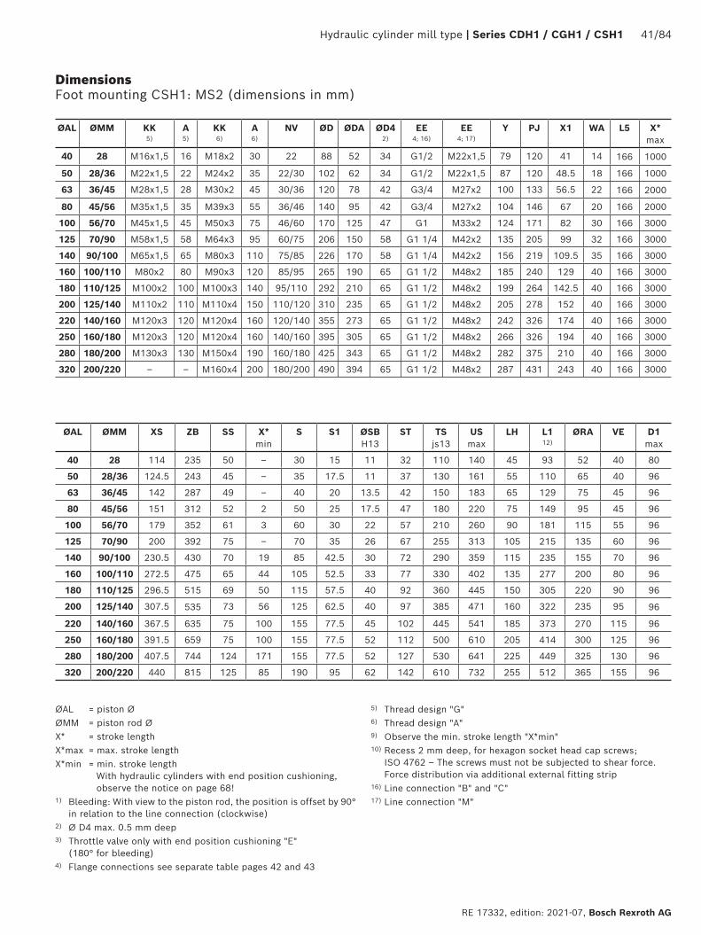
Dimensions Foot mounting CSH1: MS2 (dimensions in mm)
CSH1 MS2
View A
Hydraulic cylinder mill type | Series CDH1 / CGH1 / CSH1 41/84
RE 17332, edition: 2021-07, Bosch Rexroth AG
Dimensions Foot mounting CSH1: MS2 (dimensions in mm)
ØAL ØMM KK 5)
A 5)
KK 6)
A 6)
NV ØD ØDA ØD4 2)
EE 4; 16)
EE 4; 17)
Y PJ X1 WA L5 X* max
40 28 M16x1,5 16 M18x2 30 22 88 52 34 G1/2 M22x1,5 79 120 41 14 166 1000
50 28/36 M22x1,5 22 M24x2 35 22/30 102 62 34 G1/2 M22x1,5 87 120 48.5 18 166 1000
63 36/45 M28x1,5 28 M30x2 45 30/36 120 78 42 G3/4 M27x2 100 133 56.5 22 166 2000
80 45/56 M35x1,5 35 M39x3 55 36/46 140 95 42 G3/4 M27x2 104 146 67 20 166 2000
100 56/70 M45x1,5 45 M50x3 75 46/60 170 125 47 G1 M33x2 124 171 82 30 166 3000
125 70/90 M58x1,5 58 M64x3 95 60/75 206 150 58 G1 1/4 M42x2 135 205 99 32 166 3000
140 90/100 M65x1,5 65 M80x3 110 75/85 226 170 58 G1 1/4 M42x2 156 219 109.5 35 166 3000
160 100/110 M80x2 80 M90x3 120 85/95 265 190 65 G1 1/2 M48x2 185 240 129 40 166 3000
180 110/125 M100x2 100 M100x3 140 95/110 292 210 65 G1 1/2 M48x2 199 264 142.5 40 166 3000
200 125/140 M110x2 110 M110x4 150 110/120 310 235 65 G1 1/2 M48x2 205 278 152 40 166 3000
220 140/160 M120x3 120 M120x4 160 120/140 355 273 65 G1 1/2 M48x2 242 326 174 40 166 3000
250 160/180 M120x3 120 M120x4 160 140/160 395 305 65 G1 1/2 M48x2 266 326 194 40 166 3000
280 180/200 M130x3 130 M150x4 190 160/180 425 343 65 G1 1/2 M48x2 282 375 210 40 166 3000
320 200/220 – – M160x4 200 180/200 490 394 65 G1 1/2 M48x2 287 431 243 40 166 3000
ØAL ØMM XS ZB SS X* min
S S1 ØSB H13
ST TS js13
US max
LH L1 12)
ØRA VE D1 max
40 28 114 235 50 – 30 15 11 32 110 140 45 93 52 40 80
50 28/36 124.5 243 45 – 35 17.5 11 37 130 161 55 110 65 40 96
63 36/45 142 287 49 – 40 20 13.5 42 150 183 65 129 75 45 96
80 45/56 151 312 52 2 50 25 17.5 47 180 220 75 149 95 45 96
100 56/70 179 352 61 3 60 30 22 57 210 260 90 181 115 55 96
125 70/90 200 392 75 – 70 35 26 67 255 313 105 215 135 60 96
140 90/100 230.5 430 70 19 85 42.5 30 72 290 359 115 235 155 70 96
160 100/110 272.5 475 65 44 105 52.5 33 77 330 402 135 277 200 80 96
180 110/125 296.5 515 69 50 115 57.5 40 92 360 445 150 305 220 90 96
200 125/140 307.5 535 73 56 125 62.5 40 97 385 471 160 322 235 95 96
220 140/160 367.5 635 75 100 155 77.5 45 102 445 541 185 373 270 115 96
250 160/180 391.5 659 75 100 155 77.5 52 112 500 610 205 414 300 125 96
280 180/200 407.5 744 124 171 155 77.5 52 127 530 641 225 449 325 130 96
320 200/220 440 815 125 85 190 95 62 142 610 732 255 512 365 155 96
ØAL = piston ØØMM = piston rod ØX* = stroke lengthX*max = max. stroke lengthX*min = min. stroke length
With hydraulic cylinders with end position cushioning, observe the notice on page 68!
1) Bleeding: With view to the piston rod, the position is offset by 90° in relation to the line connection (clockwise)
2) Ø D4 max. 0.5 mm deep3) Throttle valve only with end position cushioning "E"
(180° for bleeding)4) Flange connections see separate table pages 42 and 43
5) Thread design "G"6) Thread design "A"9) Observe the min. stroke length "X*min"10) Recess 2 mm deep, for hexagon socket head cap screws;
ISO 4762 – The screws must not be subjected to shear force. Force distribution via additional external fitting strip
16) Line connection "B" and "C"17) Line connection "M"
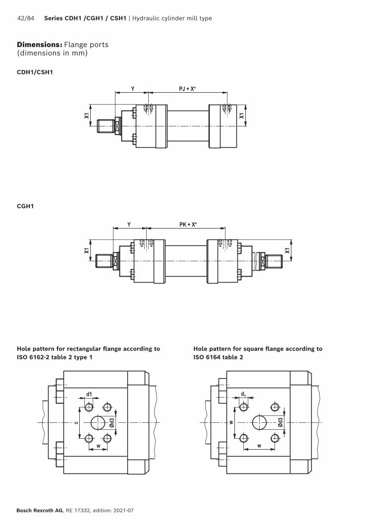
42/84 Series CDH1 /CGH1 / CSH1 | Hydraulic cylinder mill type
Bosch Rexroth AG, RE 17332, edition: 2021-07
Dimensions: Flange ports (dimensions in mm)
CDH1/CSH1
CGH1
Hole pattern for rectangular flange according to ISO 6162-2 table 2 type 1
Hole pattern for square flange according to ISO 6164 table 2
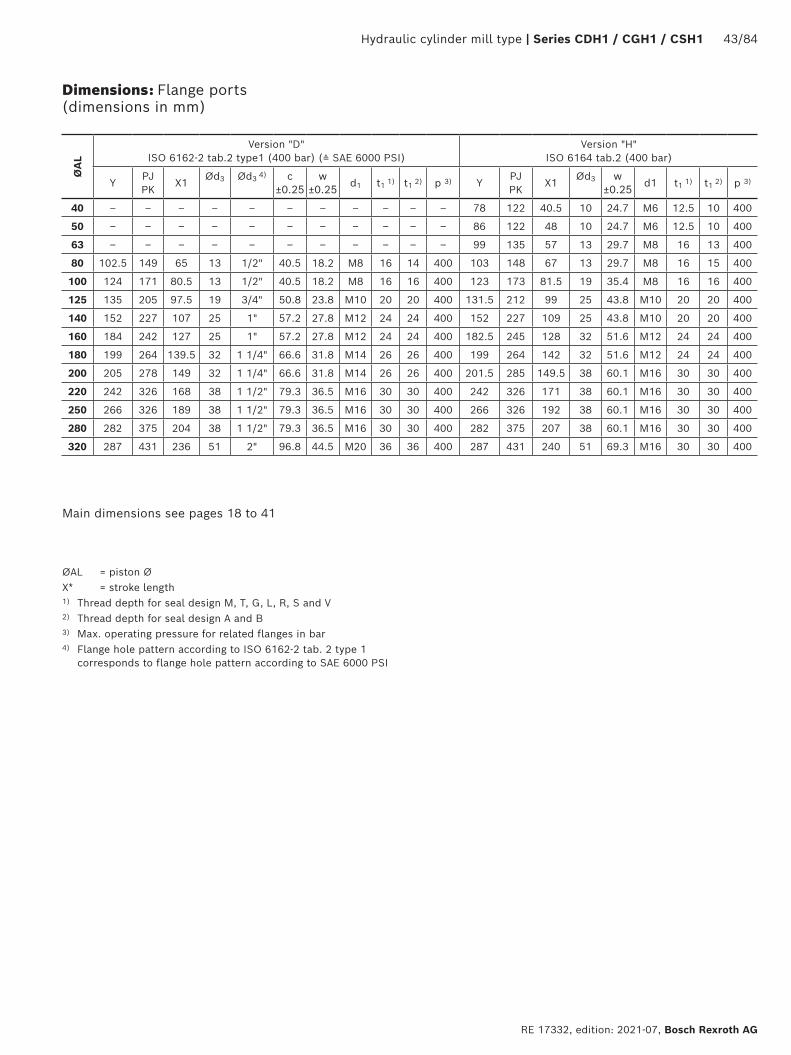
Hydraulic cylinder mill type | Series CDH1 / CGH1 / CSH1 43/84
RE 17332, edition: 2021-07, Bosch Rexroth AG
Dimensions: Flange ports (dimensions in mm)
ØA
L
Version "D"ISO 6162-2 tab.2 type1 (400 bar) (≙ SAE 6000 PSI)
Version "H"ISO 6164 tab.2 (400 bar)
YPJ PK
X1Ød3 Ød3 4) c
±0.25w
±0.25 d1 t1 1) t1 2) p 3) YPJ PK
X1Ød3 w
±0.25 d1 t1 1) t1 2) p 3)
40 – – – – – – – – – – – 78 122 40.5 10 24.7 M6 12.5 10 400
50 – – – – – – – – – – – 86 122 48 10 24.7 M6 12.5 10 400
63 – – – – – – – – – – – 99 135 57 13 29.7 M8 16 13 400
80 102.5 149 65 13 1/2" 40.5 18.2 M8 16 14 400 103 148 67 13 29.7 M8 16 15 400
100 124 171 80.5 13 1/2" 40.5 18.2 M8 16 16 400 123 173 81.5 19 35.4 M8 16 16 400
125 135 205 97.5 19 3/4" 50.8 23.8 M10 20 20 400 131.5 212 99 25 43.8 M10 20 20 400
140 152 227 107 25 1" 57.2 27.8 M12 24 24 400 152 227 109 25 43.8 M10 20 20 400
160 184 242 127 25 1" 57.2 27.8 M12 24 24 400 182.5 245 128 32 51.6 M12 24 24 400
180 199 264 139.5 32 1 1/4" 66.6 31.8 M14 26 26 400 199 264 142 32 51.6 M12 24 24 400
200 205 278 149 32 1 1/4" 66.6 31.8 M14 26 26 400 201.5 285 149.5 38 60.1 M16 30 30 400
220 242 326 168 38 1 1/2" 79.3 36.5 M16 30 30 400 242 326 171 38 60.1 M16 30 30 400
250 266 326 189 38 1 1/2" 79.3 36.5 M16 30 30 400 266 326 192 38 60.1 M16 30 30 400
280 282 375 204 38 1 1/2" 79.3 36.5 M16 30 30 400 282 375 207 38 60.1 M16 30 30 400
320 287 431 236 51 2" 96.8 44.5 M20 36 36 400 287 431 240 51 69.3 M16 30 30 400
ØAL = piston ØX* = stroke length1) Thread depth for seal design M, T, G, L, R, S and V2) Thread depth for seal design A and B3) Max. operating pressure for related flanges in bar4) Flange hole pattern according to ISO 6162-2 tab. 2 type 1
corresponds to flange hole pattern according to SAE 6000 PSI
Main dimensions see pages 18 to 41

44/84 Series CDH1 /CGH1 / CSH1 | Hydraulic cylinder mill type
Bosch Rexroth AG, RE 17332, edition: 2021-07
Dimensions: Subplates for valve mounting (SL and SV valve) (dimensions in mm)
NG6Hole pattern according to ISO 24340 form A and ISO 4401
NG10 and 20Hole pattern according to ISO 5781
Stroke
1 Port B to the piston side according to ISO 61642 Bore for locking pin3 Adapter plate for type of mounting MT4
(included in the scope of delivery for MT4)4 Line connection "B" dimensions "EE"
see also pages 18 to 41
Installation situation with MT4
Note: Valves, fittings and piping are not included in the scope of delivery!
NG30Hole pattern according to ISO 5781
Notice: Subplates for SL and SV valves (check valves)Please note: Seal designs T, G, L, R, S and V are not designed for static hold function!
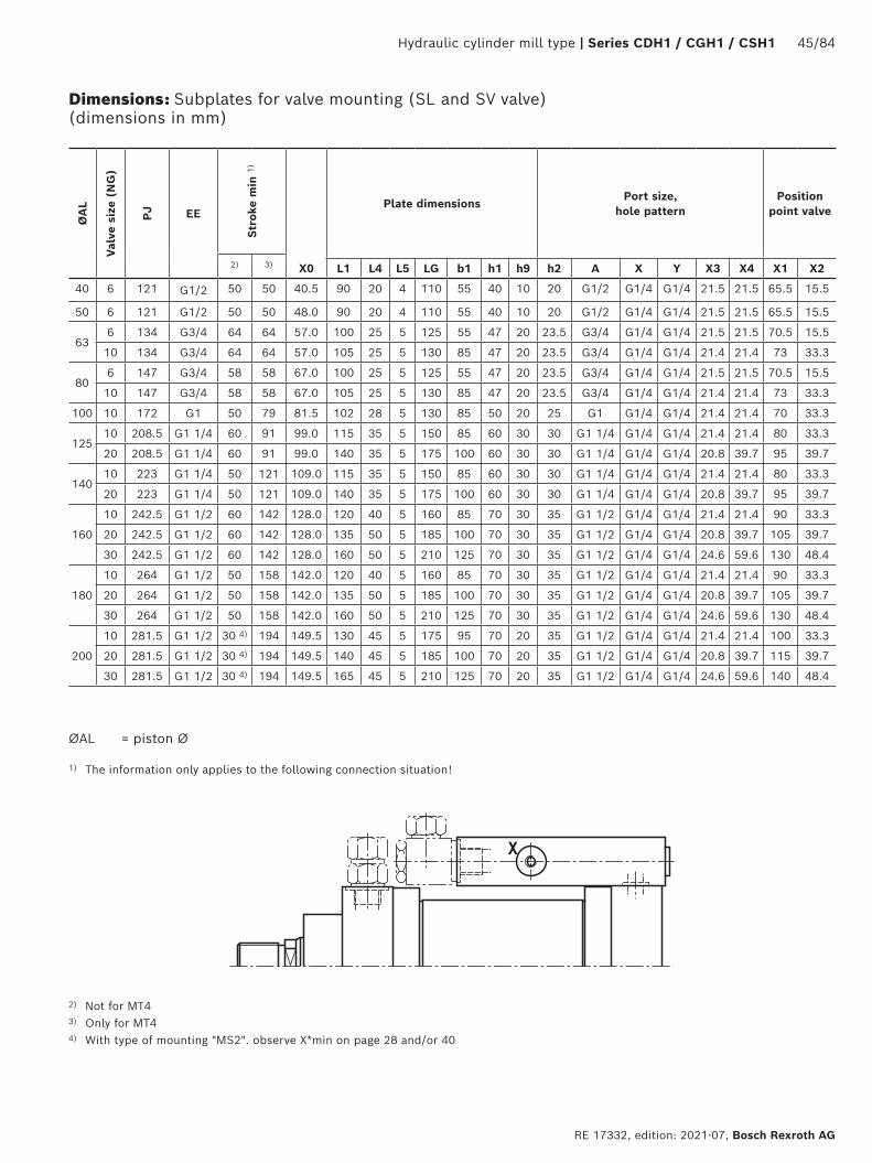
Hydraulic cylinder mill type | Series CDH1 / CGH1 / CSH1 45/84
RE 17332, edition: 2021-07, Bosch Rexroth AG
Dimensions: Subplates for valve mounting (SL and SV valve) (dimensions in mm)
ØA
L
Valv
e si
ze (
NG
)
PJ
EE
Stro
ke m
in 1
)
X0
Plate dimensionsPort size,
hole patternPosition
point valve
2) 3) L1 L4 L5 LG b1 h1 h9 h2 A X Y X3 X4 X1 X2
40 6 121 G1/2 50 50 40.5 90 20 4 110 55 40 10 20 G1/2 G1/4 G1/4 21.5 21.5 65.5 15.5
50 6 121 G1/2 50 50 48.0 90 20 4 110 55 40 10 20 G1/2 G1/4 G1/4 21.5 21.5 65.5 15.5
636 134 G3/4 64 64 57.0 100 25 5 125 55 47 20 23.5 G3/4 G1/4 G1/4 21.5 21.5 70.5 15.5
10 134 G3/4 64 64 57.0 105 25 5 130 85 47 20 23.5 G3/4 G1/4 G1/4 21.4 21.4 73 33.3
806 147 G3/4 58 58 67.0 100 25 5 125 55 47 20 23.5 G3/4 G1/4 G1/4 21.5 21.5 70.5 15.5
10 147 G3/4 58 58 67.0 105 25 5 130 85 47 20 23.5 G3/4 G1/4 G1/4 21.4 21.4 73 33.3
100 10 172 G1 50 79 81.5 102 28 5 130 85 50 20 25 G1 G1/4 G1/4 21.4 21.4 70 33.3
12510 208.5 G1 1/4 60 91 99.0 115 35 5 150 85 60 30 30 G1 1/4 G1/4 G1/4 21.4 21.4 80 33.3
20 208.5 G1 1/4 60 91 99.0 140 35 5 175 100 60 30 30 G1 1/4 G1/4 G1/4 20.8 39.7 95 39.7
14010 223 G1 1/4 50 121 109.0 115 35 5 150 85 60 30 30 G1 1/4 G1/4 G1/4 21.4 21.4 80 33.3
20 223 G1 1/4 50 121 109.0 140 35 5 175 100 60 30 30 G1 1/4 G1/4 G1/4 20.8 39.7 95 39.7
160
10 242.5 G1 1/2 60 142 128.0 120 40 5 160 85 70 30 35 G1 1/2 G1/4 G1/4 21.4 21.4 90 33.3
20 242.5 G1 1/2 60 142 128.0 135 50 5 185 100 70 30 35 G1 1/2 G1/4 G1/4 20.8 39.7 105 39.7
30 242.5 G1 1/2 60 142 128.0 160 50 5 210 125 70 30 35 G1 1/2 G1/4 G1/4 24.6 59.6 130 48.4
180
10 264 G1 1/2 50 158 142.0 120 40 5 160 85 70 30 35 G1 1/2 G1/4 G1/4 21.4 21.4 90 33.3
20 264 G1 1/2 50 158 142.0 135 50 5 185 100 70 30 35 G1 1/2 G1/4 G1/4 20.8 39.7 105 39.7
30 264 G1 1/2 50 158 142.0 160 50 5 210 125 70 30 35 G1 1/2 G1/4 G1/4 24.6 59.6 130 48.4
200
10 281.5 G1 1/2 30 4) 194 149.5 130 45 5 175 95 70 20 35 G1 1/2 G1/4 G1/4 21.4 21.4 100 33.3
20 281.5 G1 1/2 30 4) 194 149.5 140 45 5 185 100 70 20 35 G1 1/2 G1/4 G1/4 20.8 39.7 115 39.7
30 281.5 G1 1/2 30 4) 194 149.5 165 45 5 210 125 70 20 35 G1 1/2 G1/4 G1/4 24.6 59.6 140 48.4
ØAL = piston Ø
1) The information only applies to the following connection situation!
2) Not for MT43) Only for MT44) With type of mounting "MS2". observe X*min on page 28 and/or 40
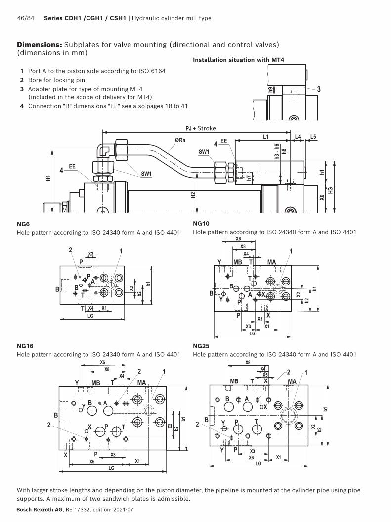
46/84 Series CDH1 /CGH1 / CSH1 | Hydraulic cylinder mill type
Bosch Rexroth AG, RE 17332, edition: 2021-07
NG6Hole pattern according to ISO 24340 form A and ISO 4401
NG16Hole pattern according to ISO 24340 form A and ISO 4401
NG10Hole pattern according to ISO 24340 form A and ISO 4401
1 Port A to the piston side according to ISO 61642 Bore for locking pin3 Adapter plate for type of mounting MT4
(included in the scope of delivery for MT4)4 Connection "B" dimensions "EE" see also pages 18 to 41
Installation situation with MT4
Stroke
NG25Hole pattern according to ISO 24340 form A and ISO 4401
With larger stroke lengths and depending on the piston diameter, the pipeline is mounted at the cylinder pipe using pipe supports. A maximum of two sandwich plates is admissible.
Dimensions: Subplates for valve mounting (directional and control valves) (dimensions in mm)
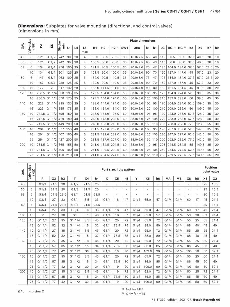
Hydraulic cylinder mill type | Series CDH1 / CGH1 / CSH1 47/84
RE 17332, edition: 2021-07, Bosch Rexroth AG
ØAL = piston Ø
ØA
L
Valv
e si
ze
(NG
)
PJ EE
Stro
ke
min
Plate dimensions
L1 L4 L5 max
H1 H2 1) H2 2) SW1 ØRa b1 h1 LG HG 1) HG 2) b2 X0 h7 h9
40 6 121 G1/2 242 90 20 4 96.0 60.5 70.5 30 16.0x2.5 65 40 110 80.5 90.5 32.5 40.5 20 10
50 6 121 G1/2 242 90 20 4 103.5 68.0 78.0 30 16.0x2.5 65 40 110 88.0 98.0 32.5 48.0 20 10
63 6 134 G3/4 276 100 25 5 121.5 80.5 100.5 36 20.0x3.0 75 47 125 104.0 124.0 37.5 57.0 23.5 20
10 134 G3/4 301 125 25 5 121.5 80.0 100.0 36 20.0x3.0 90 70 150 127.0 147.0 45 57.0 23 20
80 6 147 G3/4 263 100 25 5 132.0 90.5 110.5 36 20.0x3.0 75 47 125 114.0 134.0 37.5 67.0 23.5 20
10 147 G3/4 288 125 25 5 132.0 90.0 110.0 36 20.0x3.0 90 70 150 137.0 157.0 45 67.0 23 20
100 10 172 G1 317 132 28 5 155.0 111.5 131.5 46 25.0x4.0 90 80 160 161.5 181.5 45 81.5 30 20
125 10 208.5 G1 1/4 330 135 35 5 177.5 134.0 164.0 50 30.0x5.0 105 95 170 194.0 224.0 52.5 99.0 35 30
16 208.5 G1 1/4 370 175 35 5 177.5 144.0 174.0 50 30.0x5.0 120 100 210 199.0 229.0 60 99.0 45 30
140 10 223 G1 1/4 315 135 35 5 188.0 144.0 174.0 50 30.0x5.0 105 95 170 204.0 234.0 52.5 109.0 35 30
16 223 G1 1/4 355 175 35 5 188.0 154.0 184.0 50 30.0x5.0 120 100 210 209.0 239.0 60 109.0 45 30
160 10 242.5 G1 1/2 399 150 40 5 218.0 163.0 193.0 60 38.0x6.0 105 95 190 223.0 253.0 52.5 128.0 35 30
16 242.5 G1 1/2 429 180 40 5 218.0 178.0 208.0 60 38.0x6.0 125 105 220 233.0 263.0 62.5 128.0 50 30
25 242.5 G1 1/2 449 200 50 0 218.0 183.0 213.0 60 38.0x6.0 155 110 250 238.0 268.0 77.5 128.0 55 30
180 10 264 G1 1/2 377 150 40 5 231.5 177.0 207.0 60 38.0x6.0 105 95 190 237.0 267.0 52.5 142.0 35 30
16 264 G1 1/2 407 180 40 5 231.5 192.0 222.0 60 38.0x6.0 125 105 220 247.0 277.0 62.5 142.0 50 30
25 264 G1 1/2 427 200 50 0 231.5 197.0 227.0 60 38.0x6.0 155 110 250 252.0 282.0 77.5 142.0 55 30
200 10 281.5 G1 1/2 365 155 50 5 241.0 184.5 204.5 60 38.0x6.0 110 95 205 244.5 264.5 55 149.5 35 20
16 281.5 G1 1/2 400 190 50 5 241.0 199.5 219.5 60 38.0x6.0 125 105 240 254.5 274.5 62.5 149.5 50 20
25 281.5 G1 1/2 420 210 50 0 241.0 204.5 224.5 60 38.0x6.0 155 110 260 259.5 279.5 77.5 149.5 55 20
ØA
L
Valv
e si
ze
(NG
) Port size, hole patternPosition
point valve
P X3 h3 T X4 h4 X X5 h5 Y X6 h6 MA MB X8 h8 X1 X2
40 6 G1/2 21.5 20 G1/2 21.5 20 - - - - - - - - - - 25 15.5
50 6 G1/2 21.5 20 G1/2 21.5 20 - - - - - - - - - - 25 15.5
63 6 G3/4 21.5 23.5 G3/4 21.5 23.5 - - - - - - - - - - 30 15.5
10 G3/4 27 33 G3/4 3.5 33 G1/4 18 47 G1/4 65.0 47 G1/4 G1/4 60 17 45 21.4
80 6 G3/4 21.5 23.5 G3/4 21.5 23.5 - - - - - - - - - - 30 15.5
10 G3/4 27 33 G3/4 3.5 33 G1/4 18 47 G1/4 65.0 47 G1/4 G1/4 60 17 45 21.4
100 10 G1 27 30 G1 3.5 40 G1/4 18 57 G1/4 65.0 57 G1/4 G1/4 58 20 52 21.4
125 10 G1 1/4 27 35 G1 1/4 3.5 45 G1/4 20 72 G1/4 65.0 72 G1/4 G1/4 55 25 55 21.4
16 G1 1/4 52 32 G1 1/4 15 32 G1/4 76.5 75 G1/4 88.0 80 G1/4 G1/4 88 40 45 40
140 10 G1 1/4 27 35 G1 1/4 3.5 45 G1/4 20 72 G1/4 65.0 72 G1/4 G1/4 55 25 55 21.4
16 G1 1/4 52 32 G1 1/4 15 32 G1/4 76.5 75 G1/4 88.0 80 G1/4 G1/4 88 40 45 40
160 10 G1 1/2 27 35 G1 1/2 3.5 45 G1/4 20 72 G1/4 65.0 72 G1/4 G1/4 55 25 60 21.4
16 G1 1/2 57 35 G1 1/2 15 34 G1/4 76.5 80 G1/4 86.0 85 G1/4 G1/4 86 45 50 40
25 G1 1/2 77 42 G1 1/2 30 34 G1/4 19 90 G1/4 109.0 90 G1/4 G1/4 103 50 50 52.1
180 10 G1 1/2 27 35 G1 1/2 3.5 45 G1/4 20 72 G1/4 65.0 72 G1/4 G1/4 55 25 60 21.4
16 G1 1/2 57 35 G1 1/2 15 34 G1/4 76.5 80 G1/4 86.0 85 G1/4 G1/4 86 45 50 40
25 G1 1/2 77 42 G1 1/2 30 34 G1/4 19 90 G1/4 109.0 90 G1/4 G1/4 103 50 50 52.1
200 10 G1 1/2 27 35 G1 1/2 3.5 45 G1/4 19 72 G1/4 62.0 72 G1/4 G1/4 50 25 72 21.4
16 G1 1/2 57 35 G1 1/2 15 34 G1/4 76.5 80 G1/4 86.0 85 G1/4 G1/4 86 45 60 40
25 G1 1/2 77 42 G1 1/2 30 34 G1/4 19 90 G1/4 109.0 90 G1/4 G1/4 103 50 60 52.1
Dimensions: Subplates for valve mounting (directional and control valves) (dimensions in mm)
1) Not for MT42) Only for MT4
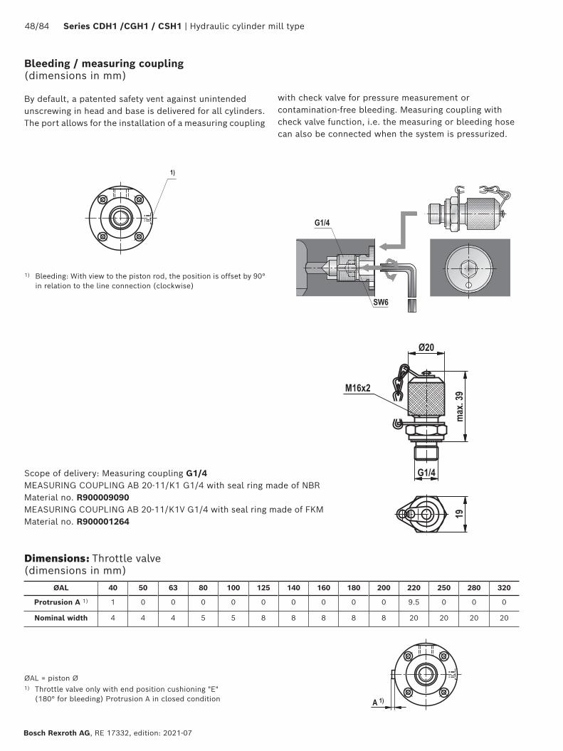
48/84 Series CDH1 /CGH1 / CSH1 | Hydraulic cylinder mill type
Bosch Rexroth AG, RE 17332, edition: 2021-07
By default, a patented safety vent against unintended unscrewing in head and base is delivered for all cylinders.The port allows for the installation of a measuring coupling
Scope of delivery: Measuring coupling G1/4MEASURING COUPLING AB 20-11/K1 G1/4 with seal ring made of NBR Material no. R900009090 MEASURING COUPLING AB 20-11/K1V G1/4 with seal ring made of FKM Material no. R900001264
1) Bleeding: With view to the piston rod, the position is offset by 90° in relation to the line connection (clockwise)
ØAL 40 50 63 80 100 125 140 160 180 200 220 250 280 320
Protrusion A 1) 1 0 0 0 0 0 0 0 0 0 9.5 0 0 0
Nominal width 4 4 4 5 5 8 8 8 8 8 20 20 20 20
with check valve for pressure measurement or contamination-free bleeding. Measuring coupling with check valve function, i.e. the measuring or bleeding hose can also be connected when the system is pressurized.
ØAL = piston Ø1) Throttle valve only with end position cushioning "E"
(180° for bleeding) Protrusion A in closed condition
Bleeding / measuring coupling (dimensions in mm)
Dimensions: Throttle valve (dimensions in mm)

Hydraulic cylinder mill type | Series CDH1 / CGH1 / CSH1 49/84
RE 17332, edition: 2021-07, Bosch Rexroth AG
Inductive proximity switches are used as reliable end position control for hydraulic cylinders. They are an important element for the safe and exact monitoring of safety equipment, lockings and/or other machine functions in their end position by means of the output of signals. The proximity switch which is high-pressure-resistant up to 500 bar works in a contactless manner.
Pin assignment
BN
BK
BU
BN brownBK blackBU blue
Consequently, it is wear-free. The proximity switch has been set at the factory. The switching distance must not be adjusted. The lock nut of the proximity switch is marked at the factory using sealing wax. On versions with proximity switch, the cylinders are provided with proximity switches on both sides.
Proximity switch (dimensions in mm)
Electrical
Function type PNP normally open contact
Admissible pressure bar 500
Operating voltage V DC 10 … 30
including residual ripple % ≤ 15
Voltage drop V ≤ 15
Rated operating voltage V DC 24
Rated operating current mA 200
Idle current mA ≤ 8
Residual current μA ≤ 10
Repetition accuracy % ≤ 5
Hysteresis % ≤ 15
Ambient temperature range °C -25 … +80
Temperature drift % ≤ 10
Switching frequency Hz 1000
Protection class according to DIN EN 60529
Active area IP68
Proximity switch IP67
Housing material Material no. 1.4104
Technical data (For applications outside these values, please consult us!)

50/84 Series CDH1 /CGH1 / CSH1 | Hydraulic cylinder mill type
Bosch Rexroth AG, RE 17332, edition: 2021-07
CDH1
CGH1
Mating connector with 5 m cable Material no. R913016852 (mating connector is not included in the scope of delivery, must be ordered separately)
Mating connector, angled with 5 m cable (position of the cable outlet cannot be defined) Material no. R988064311 (mating connector is not included in the scope of delivery, must be ordered separately)
Installation space for mating connector
Dimensions: Proximity switch (dimensions in mm)
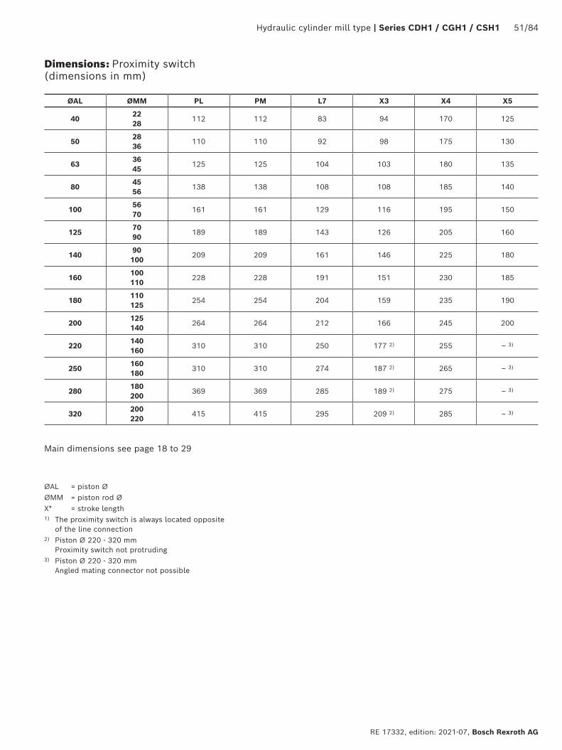
Hydraulic cylinder mill type | Series CDH1 / CGH1 / CSH1 51/84
RE 17332, edition: 2021-07, Bosch Rexroth AG
Dimensions: Proximity switch (dimensions in mm)
ØAL ØMM PL PM L7 X3 X4 X5
4022 28
112 112 83 94 170 125
5028 36
110 110 92 98 175 130
6336 45
125 125 104 103 180 135
8045 56
138 138 108 108 185 140
10056 70
161 161 129 116 195 150
12570 90
189 189 143 126 205 160
14090 100
209 209 161 146 225 180
160100 110
228 228 191 151 230 185
180110 125
254 254 204 159 235 190
200125 140
264 264 212 166 245 200
220140 160
310 310 250 177 2) 255 – 3)
250160 180
310 310 274 187 2) 265 – 3)
280180 200
369 369 285 189 2) 275 – 3)
320200 220
415 415 295 209 2) 285 – 3)
ØAL = piston ØØMM = piston rod ØX* = stroke length1) The proximity switch is always located opposite
of the line connection2) Piston Ø 220 - 320 mm
Proximity switch not protruding3) Piston Ø 220 - 320 mm
Angled mating connector not possible
Main dimensions see page 18 to 29
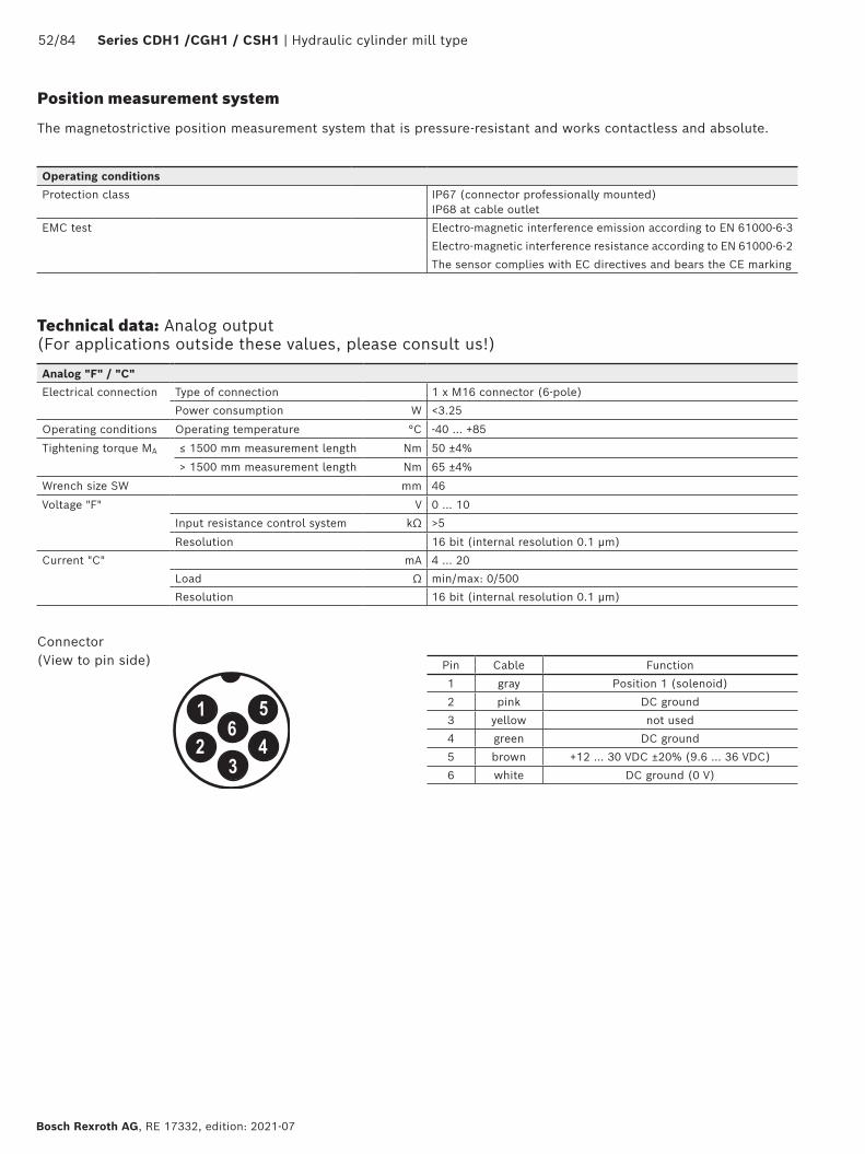
52/84 Series CDH1 /CGH1 / CSH1 | Hydraulic cylinder mill type
Bosch Rexroth AG, RE 17332, edition: 2021-07
Position measurement system
The magnetostrictive position measurement system that is pressure-resistant and works contactless and absolute.
Analog "F" / "C"
Electrical connection Type of connection 1 x M16 connector (6-pole)
Power consumption W <3.25
Operating conditions Operating temperature °C -40 … +85
Tightening torque MA ≤ 1500 mm measurement length Nm 50 ±4%
> 1500 mm measurement length Nm 65 ±4%
Wrench size SW mm 46
Voltage "F" V 0 … 10
Input resistance control system kΩ >5
Resolution 16 bit (internal resolution 0.1 μm)
Current "C" mA 4 … 20
Load Ω min/max: 0/500
Resolution 16 bit (internal resolution 0.1 μm)
Operating conditions
Protection class IP67 (connector professionally mounted) IP68 at cable outlet
EMC test Electro-magnetic interference emission according to EN 61000-6-3
Electro-magnetic interference resistance according to EN 61000-6-2
The sensor complies with EC directives and bears the CE marking
Technical data: Analog output (For applications outside these values, please consult us!)
Pin Cable Function
1 gray Position 1 (solenoid)
2 pink DC ground
3 yellow not used
4 green DC ground
5 brown +12 … 30 VDC ±20% (9.6 … 36 VDC)
6 white DC ground (0 V)
Connector (View to pin side)

Hydraulic cylinder mill type | Series CDH1 / CGH1 / CSH1 53/84
RE 17332, edition: 2021-07, Bosch Rexroth AG
MF3, MF4, MT4, MS2MP3, MP5
1) For analog output:6-pole amphenol mating connector, material no. R900072231(mating connector is not included in the scope of delivery, must be ordered separately)
1) For digital output:7-pole amphenol mating connector, material no. R900079551(mating connector is not included in the scope of delivery, must be ordered separately)
Digital "D" / "S"
Electrical connection Type of connection 1 x M16 connector (7-pole)
Power consumption W 1.2 typical
Operating conditions Operating temperature °C -40 … +85
Tightening torque MA ≤ 1500 mm measurement length Nm 50 ±4%
> 1500 mm measurement length Nm 65 ±4%
Wrench size SW mm 46
SSI "D" Interface SSI 24 bit (RS-485/RS-422)
Resolution μm 5
Direction of measurement asynchronious forward
Data format Gray
SSI "S" Interface SSI 24 bit (RS-485/RS-422)
Resolution μm 1
Direction of measurement synchronious forward
Data format Gray
Pin Cable Function
1 gray Data (-)
2 pink Data (+)
3 yellow Clock (+)
4 green Clock (-)
5 brown +12 … 30 VDC ±20% (9.6 … 36 VDC)
6 white DC ground (0 V)
7 - not used
77
Connector (View to pin side)
Types of mounting
Technical data: Digital output (For applications outside these values, please consult us!)
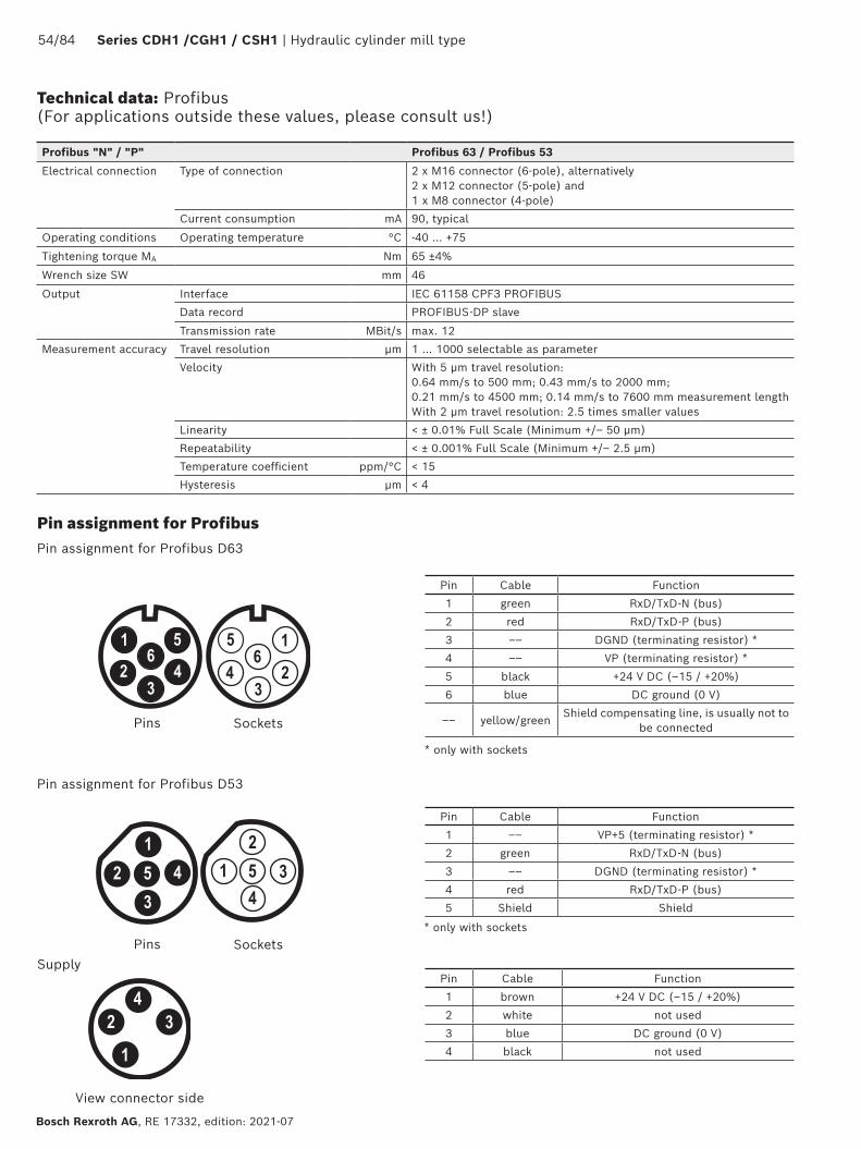
54/84 Series CDH1 /CGH1 / CSH1 | Hydraulic cylinder mill type
Bosch Rexroth AG, RE 17332, edition: 2021-07
Technical data: Profibus (For applications outside these values, please consult us!)
Pin assignment for Profibus Pin assignment for Profibus D63
Pins
Pins
Sockets
Sockets
* only with sockets
Pin Cable Function
1 green RxD/TxD-N (bus)
2 red RxD/TxD-P (bus)
3 –– DGND (terminating resistor) *
4 –– VP (terminating resistor) *
5 black +24 V DC (–15 / +20%)
6 blue DC ground (0 V)
–– yellow/greenShield compensating line, is usually not to
be connected
Profibus "N" / "P" Profibus 63 / Profibus 53
Electrical connection Type of connection 2 x M16 connector (6-pole), alternatively 2 x M12 connector (5-pole) and 1 x M8 connector (4-pole)
Current consumption mA 90, typical
Operating conditions Operating temperature °C -40 … +75
Tightening torque MA Nm 65 ±4%
Wrench size SW mm 46
Output Interface IEC 61158 CPF3 PROFIBUS
Data record PROFIBUS-DP slave
Transmission rate MBit/s max. 12
Measurement accuracy Travel resolution μm 1 … 1000 selectable as parameter
Velocity With 5 μm travel resolution: 0.64 mm/s to 500 mm; 0.43 mm/s to 2000 mm; 0.21 mm/s to 4500 mm; 0.14 mm/s to 7600 mm measurement lengthWith 2 μm travel resolution: 2.5 times smaller values
Linearity < ± 0.01% Full Scale (Minimum +/– 50 μm)
Repeatability < ± 0.001% Full Scale (Minimum +/– 2.5 μm)
Temperature coefficient ppm/°C < 15
Hysteresis μm < 4
Pin assignment for Profibus D53
Pin Cable Function
1 –– VP+5 (terminating resistor) *
2 green RxD/TxD-N (bus)
3 –– DGND (terminating resistor) *
4 red RxD/TxD-P (bus)
5 Shield Shield
* only with sockets
Supply
View connector side
Pin Cable Function
1 brown +24 V DC (–15 / +20%)
2 white not used
3 blue DC ground (0 V)
4 black not used
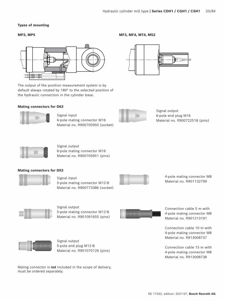
Hydraulic cylinder mill type | Series CDH1 / CGH1 / CSH1 55/84
RE 17332, edition: 2021-07, Bosch Rexroth AG
MF3, MF4, MT4, MS2
Types of mounting
MP3, MP5
The output of the position measurement system is by default always rotated by 180° to the selected position of the hydraulic connection in the cylinder base.
Mating connector is not included in the scope of delivery, must be ordered separately.
Mating connectors for D63
Signal output6-pole mating connector M16Material no. R900705951 (pins)
Signal output6-pole end plug M16Material no. R900722518 (pins)
Signal input6-pole mating connector M16Material no. R900705950 (socket)
Mating connectors for D53
Signal input5-pole mating connector M12-BMaterial no. R900773386 (socket)
Signal output5-pole mating connector M12-BMaterial no. R901091655 (pins)
Signal output5-pole end plug M12-BMaterial no. R901070126 (pins)
4-pole mating connector M8Material no. R901132799
Connection cable 5 m with 4-pole mating connector M8Material no. R901213191
Connection cable 10 m with 4-pole mating connector M8Material no. R913008737
Connection cable 15 m with 4-pole mating connector M8Material no. R913008738

56/84 Series CDH1 /CGH1 / CSH1 | Hydraulic cylinder mill type
Bosch Rexroth AG, RE 17332, edition: 2021-07
Technical data: IO-Link (For applications outside these values, please consult us!)
IO-Link "L" IO-Link V1.1
Electrical connection Type of connection 1 x M12 connector (4-pole)
Operating voltage VDC +24 (± 25%) / residual ripple ≤ 0.28 Vpp
Current consumption mA < 50
Operating conditions Operating temperature °C -40 … +75
Tightening torque MA Nm 50 ±4%
Wrench size SW mm 34
Output Interface Digital
Transmission record IO-Link V1.1
Data format Bit 32 signed (position in μm)
Data transmission rate COM3 (230.4 kBaud)
Process data Device - Master Bytes 4
Process data Master - Device Bytes 0
Measured variable MBit/s Position
Measured values Resolution 1) μm 5; 10; 20; 50 or 100
Cycle time: ms Minimum 1 (depending on master)
Linearity 2) % ≤ ±0.02 F.S. (Minimum ±60 μm)
Measurement repetition accuracy % ≤ ±0.005 F.S. (Minimum ±20 μm)
Pin Function
1 + 24 VDC (± 25%)
2 DI / DQ
3 DC ground (0 V)
4 C / Q
1) Selectable via IO-Link Master.2) Tested with position magnet 251 416-2.
M12 connector (A-coded) View to sensor
M12 A-coded (5-pole), straightMaterial number: R913045873
M12 A-coded (5-pole), angledMaterial number: R901500328
Mating connector is not included in the scope of delivery, must be ordered separately.
Mating connectors
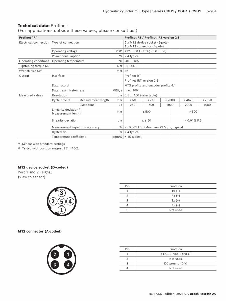
Hydraulic cylinder mill type | Series CDH1 / CGH1 / CSH1 57/84
RE 17332, edition: 2021-07, Bosch Rexroth AG
Technical data: Profinet (For applications outside these values, please consult us!)
1) Sensor with standard settings2) Tested with position magnet 251 416-2.
M12 device socket (D-coded) Port 1 and 2 - signal (View to sensor)
Pin Function
1 Tx (+)
2 Rx (+)
3 Tx (−)
4 Rx (−)
5 Not used
3
12 45
Pin Function
1 +12…30 VDC (±20%)
2 Not used
3 DC ground (0 V)
4 Not used
Profinet "R" Profinet RT / Profinet IRT version 2.3
Electrical connection Type of connection 2 x M12 device socket (5-pole)1 x M12 connector (4-pole)
Operating voltage VDC +12 … 30 (± 20%) (9.6 … 36)
Power consumption W < 4 typical
Operating conditions Operating temperature °C -40 … +85
Tightening torque MA Nm 65 ±4%
Wrench size SW mm 46
Output Interface Profinet RT
Profinet IRT version 2.3
Data record MTS profile and encoder profile 4.1
Data transmission rate MBit/s max. 100
Measured values Resolution μm 0,5 … 100 (selectable)
Cycle time 1) Measurement length mm ≤ 50 ≤ 715 ≤ 2000 ≤ 4675 ≤ 7620
Cycle time: μs 250 500 1000 2000 4000
Linearity deviation 2)
Measurement length mm ≤ 500 > 500
linearity deviation μm ≤ ± 50 < 0.01% F.S
Measurement repetition accuracy % ≤ ±0.001 F.S. (Minimum ±2.5 μm) typical
Hysteresis μm < 4 typical
Temperature coefficient ppm/K < 15 typical
M12 connector (A-coded)
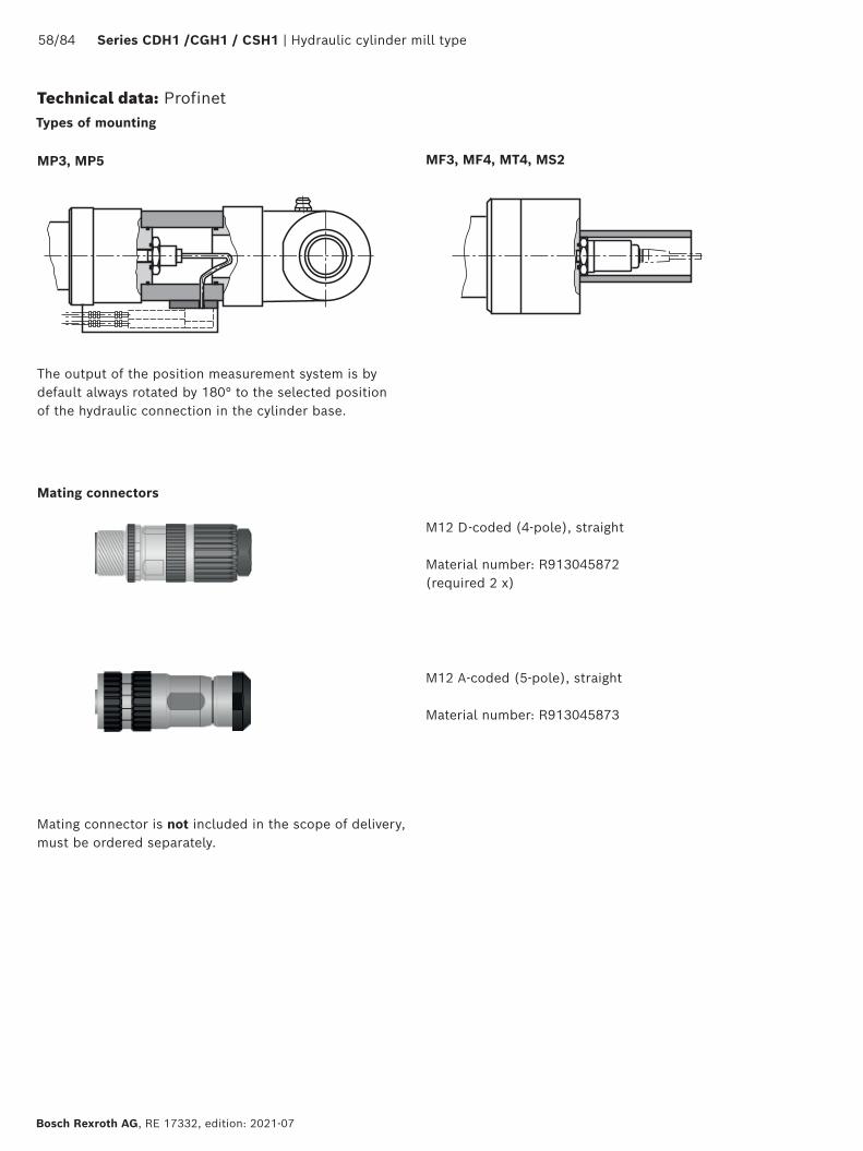
58/84 Series CDH1 /CGH1 / CSH1 | Hydraulic cylinder mill type
Bosch Rexroth AG, RE 17332, edition: 2021-07
Technical data: Profinet
M12 D-coded (4-pole), straight
Material number: R913045872(required 2 x)
M12 A-coded (5-pole), straight Material number: R913045873
MP3, MP5
The output of the position measurement system is by default always rotated by 180° to the selected position of the hydraulic connection in the cylinder base.
MF3, MF4, MT4, MS2
Types of mounting
Mating connector is not included in the scope of delivery, must be ordered separately.
Mating connectors

59/84 Series CDH1 /CGH1 / CSH1 | Hydraulic cylinder mill type
Bosch Rexroth AG, RE 17332, edition: 2021-07
Plain clevis CSA (dimensions in mm)
ØAL Type Material no. AW Øb C CAØCK H11
EM -0.4
KK LE L1m 2)
kgC0 3)
kNFadm 4)
kN
40 CSA 16 R900303150 17 28 56 50 25 23 M16x1,5 25 80 0.43 72 25.9
50 CSA 22 R900303151 23 34 64 60 30 28 M22x1,5 30 94 0.7 106 38.2
63 CSA 28 R900303152 29 44 78 70 35 30 M28x1,5 40 112 1.1 153 55.1
80 CSA 35 R900303153 36 55 94 85 40 35 M35x1,5 45 135 2.0 250 90.0
100 CSA 45 R900303154 46 70 116 105 50 40 M45x1,5 55 168 3.3 365 131.4
125 CSA 58 R900303155 59 87 130 130 60 50 M58x1,5 65 200 5.5 400 144.0
140 CSA 65 R900303156 66 93 154 150 70 55 M65x1,5 75 232 8.6 540 194.4
160 CSA 80 R900303157 81 125 176 170 80 60 M80x2 80 265 12.2 670 241.2
180 CSA100 R900303158 101 143 206 210 90 65 M100x2 90 323 21.5 980 352.8
200 CSA110 R900303159 111 153 230 235 100 70 M110x2 105 360 27.5 1120 403.2
The specified dimensions are maximum values and may differ depending on the manufacturer. The following values are excluded: CA, CK, EM, KKThe plain clevis must always be screwed against the shoulder of the piston rod and secured against loosening!
ØAL 40-200 mm
ØAL = piston Ø1) Grease nipple, cone head form A according to DIN 714122) m = weight of plain clevis in kg3) C0 = static load rating of the plain clevis4) Fadm = max. admissible load of the plain clevis for oscillatory or
alternating loads
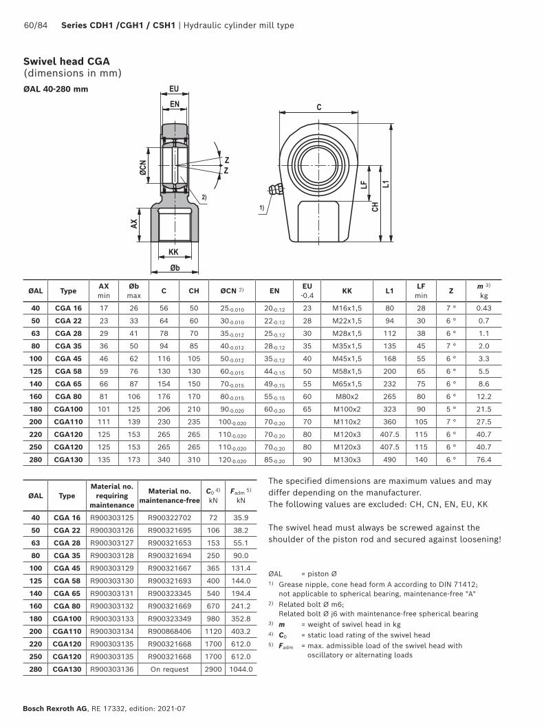
60/84 Series CDH1 /CGH1 / CSH1 | Hydraulic cylinder mill type
Bosch Rexroth AG, RE 17332, edition: 2021-07
ØAL TypeAX min
Øb max
C CH ØCN 2) ENEU -0.4
KK L1LF min
Zm 3) kg
40 CGA 16 17 26 56 50 25-0.010 20-0.12 23 M16x1,5 80 28 7 ° 0.43
50 CGA 22 23 33 64 60 30-0.010 22-0.12 28 M22x1,5 94 30 6 ° 0.7
63 CGA 28 29 41 78 70 35-0.012 25-0.12 30 M28x1,5 112 38 6 ° 1.1
80 CGA 35 36 50 94 85 40-0.012 28-0.12 35 M35x1,5 135 45 7 ° 2.0
100 CGA 45 46 62 116 105 50-0.012 35-0.12 40 M45x1,5 168 55 6 ° 3.3
125 CGA 58 59 76 130 130 60-0.015 44-0.15 50 M58x1,5 200 65 6 ° 5.5
140 CGA 65 66 87 154 150 70-0.015 49-0.15 55 M65x1,5 232 75 6 ° 8.6
160 CGA 80 81 106 176 170 80-0.015 55-0.15 60 M80x2 265 80 6 ° 12.2
180 CGA100 101 125 206 210 90-0.020 60-0.20 65 M100x2 323 90 5 ° 21.5
200 CGA110 111 139 230 235 100-0.020 70-0.20 70 M110x2 360 105 7 ° 27.5
220 CGA120 125 153 265 265 110-0.020 70-0.20 80 M120x3 407.5 115 6 ° 40.7
250 CGA120 125 153 265 265 110-0.020 70-0.20 80 M120x3 407.5 115 6 ° 40.7
280 CGA130 135 173 340 310 120-0.020 85-0.20 90 M130x3 490 140 6 ° 76.4
ØAL TypeMaterial no.
requiring maintenance
Material no. maintenance-free
C0 4)
kNFadm 5)
kN
40 CGA 16 R900303125 R900322702 72 35.9
50 CGA 22 R900303126 R900321695 106 38.2
63 CGA 28 R900303127 R900321653 153 55.1
80 CGA 35 R900303128 R900321694 250 90.0
100 CGA 45 R900303129 R900321667 365 131.4
125 CGA 58 R900303130 R900321693 400 144.0
140 CGA 65 R900303131 R900323345 540 194.4
160 CGA 80 R900303132 R900321669 670 241.2
180 CGA100 R900303133 R900323349 980 352.8
200 CGA110 R900303134 R900868406 1120 403.2
220 CGA120 R900303135 R900321668 1700 612.0
250 CGA120 R900303135 R900321668 1700 612.0
280 CGA130 R900303136 On request 2900 1044.0
ØAL 40-280 mm
The specified dimensions are maximum values and may differ depending on the manufacturer. The following values are excluded: CH, CN, EN, EU, KK
The swivel head must always be screwed against the shoulder of the piston rod and secured against loosening!
ØAL = piston Ø1) Grease nipple, cone head form A according to DIN 71412;
not applicable to spherical bearing, maintenance-free "A"2) Related bolt Ø m6;
Related bolt Ø j6 with maintenance-free spherical bearing3) m = weight of swivel head in kg4) C0 = static load rating of the swivel head5) Fadm = max. admissible load of the swivel head with
oscillatory or alternating loads
Swivel head CGA (dimensions in mm)
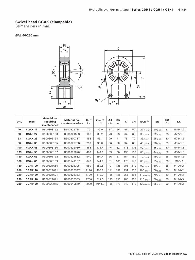
Hydraulic cylinder mill type | Series CDH1 / CGH1 / CSH1 61/84
RE 17332, edition: 2021-07, Bosch Rexroth AG
ØAL TypeMaterial no.
requiring maintenance
Material no. maintenance-free
C0 4)
kNFadm 5)
kNAX min
Øb max
C CH ØCN 2) ENEU -0.4
KK
40 CGAK 16 R900303162 R900321784 72 35.9 17 26 56 50 25-0.010 20-0.12 23 M16x1,5
50 CGAK 22 R900303163 R900321683 106 38.2 23 33 64 60 30-0.010 22-0.12 28 M22x1,5
63 CGAK 28 R900303164 R900300717 153 55.1 29 41 78 70 35-0.012 25-0.12 30 M28x1,5
80 CGAK 35 R900303165 R900322738 250 90.0 36 50 94 85 40-0.012 28-0.12 35 M35x1,5
100 CGAK 45 R900303166 R900322019 365 131.4 46 62 116 105 50-0.012 35-0.12 40 M45x1,5
125 CGAK 58 R900303167 R900322020 400 144.0 59 76 130 130 60-0.015 44-0.15 50 M58x1,5
140 CGAK 65 R900303168 R900324812 540 194.4 66 87 154 150 70-0.015 49-0.15 55 M65x1,5
160 CGAK 80 R900303169 R900541157 670 241.2 81 106 176 170 80-0.015 55-0.15 60 M80x2
180 CGAK100 R900321655 R900323305 980 352.8 101 125 206 210 90-0.020 60-0.20 65 M100x2
200 CGAK110 R900321691 R900329997 1120 403.2 111 139 231 235 100-0.020 70-0.20 70 M110x2
220 CGAK120 R900321621 R900323333 1700 612.0 125 155 266 265 110-0.020 70-0.20 80 M120x3
250 CGAK120 R900321621 R900323333 1700 612.0 125 153 265 265 110-0.020 70-0.20 80 M120x3
280 CGAK130 R900322015 R900540850 2900 1044.0 135 173 340 310 120-0.020 85-0.20 90 M130x3
ØAL 40-280 mm
Swivel head CGAK (clampable) (dimensions in mm)
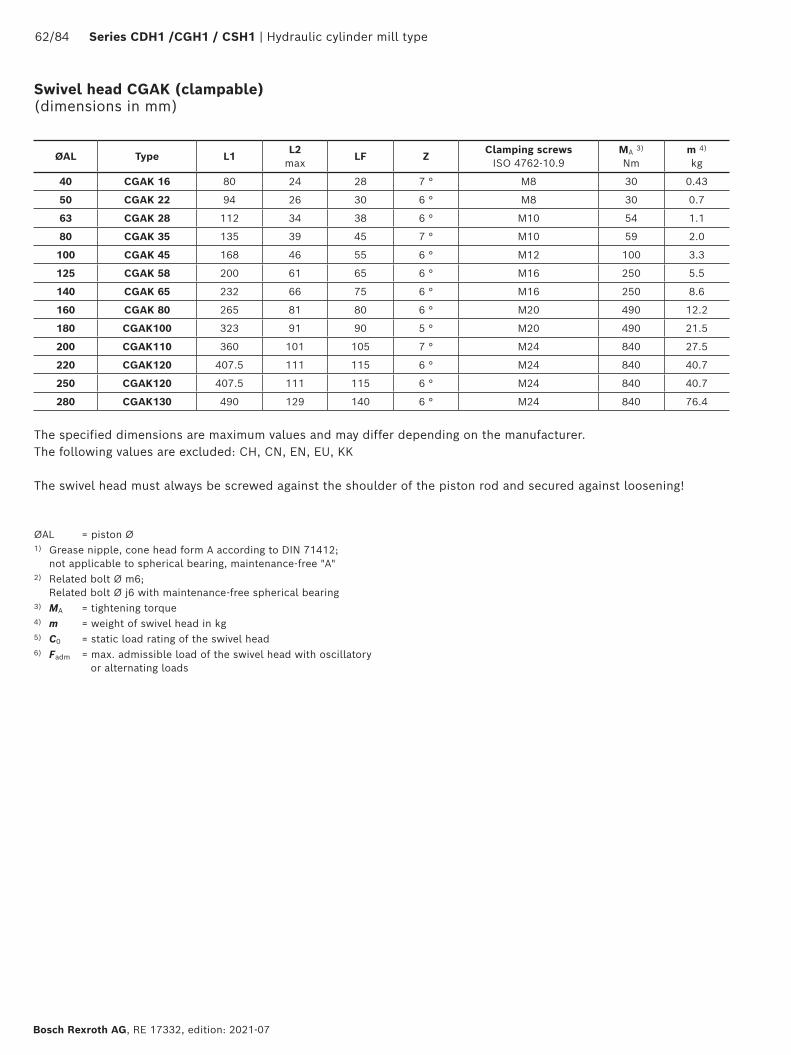
62/84 Series CDH1 /CGH1 / CSH1 | Hydraulic cylinder mill type
Bosch Rexroth AG, RE 17332, edition: 2021-07
The specified dimensions are maximum values and may differ depending on the manufacturer. The following values are excluded: CH, CN, EN, EU, KK
The swivel head must always be screwed against the shoulder of the piston rod and secured against loosening!
ØAL Type L1L2
maxLF Z
Clamping screws ISO 4762-10.9
MA 3) Nm
m 4) kg
40 CGAK 16 80 24 28 7 ° M8 30 0.43
50 CGAK 22 94 26 30 6 ° M8 30 0.7
63 CGAK 28 112 34 38 6 ° M10 54 1.1
80 CGAK 35 135 39 45 7 ° M10 59 2.0
100 CGAK 45 168 46 55 6 ° M12 100 3.3
125 CGAK 58 200 61 65 6 ° M16 250 5.5
140 CGAK 65 232 66 75 6 ° M16 250 8.6
160 CGAK 80 265 81 80 6 ° M20 490 12.2
180 CGAK100 323 91 90 5 ° M20 490 21.5
200 CGAK110 360 101 105 7 ° M24 840 27.5
220 CGAK120 407.5 111 115 6 ° M24 840 40.7
250 CGAK120 407.5 111 115 6 ° M24 840 40.7
280 CGAK130 490 129 140 6 ° M24 840 76.4
ØAL = piston Ø1) Grease nipple, cone head form A according to DIN 71412;
not applicable to spherical bearing, maintenance-free "A"2) Related bolt Ø m6;
Related bolt Ø j6 with maintenance-free spherical bearing3) MA = tightening torque4) m = weight of swivel head in kg5) C0 = static load rating of the swivel head6) Fadm = max. admissible load of the swivel head with oscillatory
or alternating loads
Swivel head CGAK (clampable) (dimensions in mm)
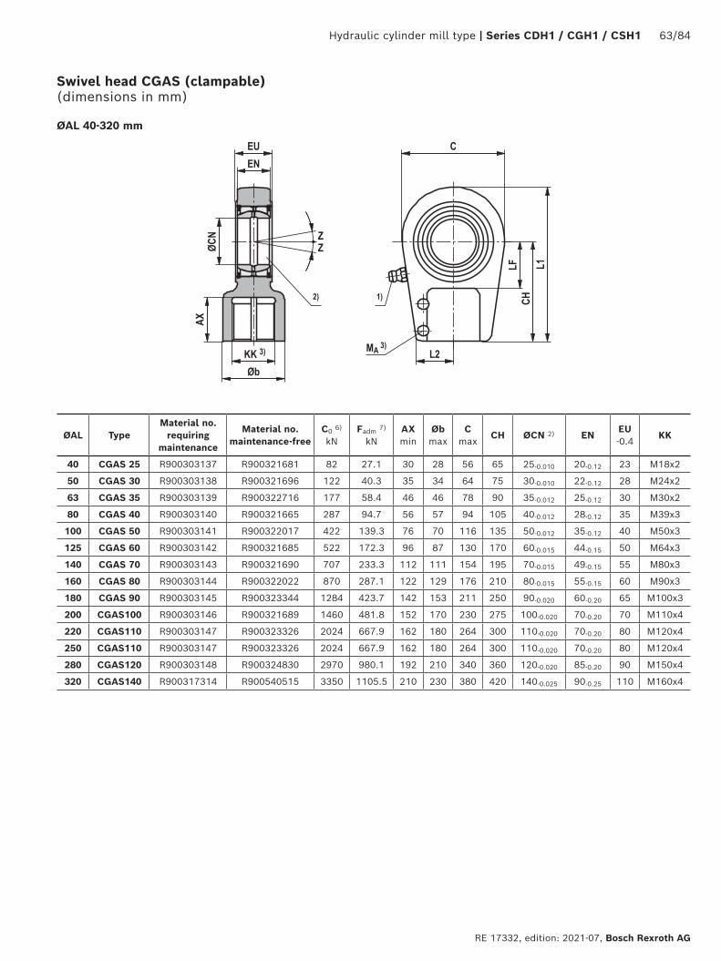
Hydraulic cylinder mill type | Series CDH1 / CGH1 / CSH1 63/84
RE 17332, edition: 2021-07, Bosch Rexroth AG
Swivel head CGAS (clampable) (dimensions in mm)
ØAL TypeMaterial no.
requiring maintenance
Material no. maintenance-free
C0 6) kN
Fadm 7) kN
AX min
Øb max
C max
CH ØCN 2) ENEU -0.4
KK
40 CGAS 25 R900303137 R900321681 82 27.1 30 28 56 65 25-0.010 20-0.12 23 M18x2
50 CGAS 30 R900303138 R900321696 122 40.3 35 34 64 75 30-0.010 22-0.12 28 M24x2
63 CGAS 35 R900303139 R900322716 177 58.4 46 46 78 90 35-0.012 25-0.12 30 M30x2
80 CGAS 40 R900303140 R900321665 287 94.7 56 57 94 105 40-0.012 28-0.12 35 M39x3
100 CGAS 50 R900303141 R900322017 422 139.3 76 70 116 135 50-0.012 35-0.12 40 M50x3
125 CGAS 60 R900303142 R900321685 522 172.3 96 87 130 170 60-0.015 44-0.15 50 M64x3
140 CGAS 70 R900303143 R900321690 707 233.3 112 111 154 195 70-0.015 49-0.15 55 M80x3
160 CGAS 80 R900303144 R900322022 870 287.1 122 129 176 210 80-0.015 55-0.15 60 M90x3
180 CGAS 90 R900303145 R900323344 1284 423.7 142 153 211 250 90-0.020 60-0.20 65 M100x3
200 CGAS100 R900303146 R900321689 1460 481.8 152 170 230 275 100-0.020 70-0.20 70 M110x4
220 CGAS110 R900303147 R900323326 2024 667.9 162 180 264 300 110-0.020 70-0.20 80 M120x4
250 CGAS110 R900303147 R900323326 2024 667.9 162 180 264 300 110-0.020 70-0.20 80 M120x4
280 CGAS120 R900303148 R900324830 2970 980.1 192 210 340 360 120-0.020 85-0.20 90 M150x4
320 CGAS140 R900317314 R900540515 3350 1105.5 210 230 380 420 140-0.025 90-0.25 110 M160x4
ØAL 40-320 mm
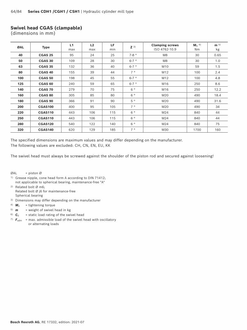
64/84 Series CDH1 /CGH1 / CSH1 | Hydraulic cylinder mill type
Bosch Rexroth AG, RE 17332, edition: 2021-07
Swivel head CGAS (clampable) (dimensions in mm)
The specified dimensions are maximum values and may differ depending on the manufacturer. The following values are excluded: CH, CN, EN, EU, KK
The swivel head must always be screwed against the shoulder of the piston rod and secured against loosening!
ØAL TypeL1
maxL2
maxLF min
Z 3) Clamping screws ISO 4762-10.9
MA 4) Nm
m 5) kg
40 CGAS 25 95 24 25 7-8 ° M8 30 0.65
50 CGAS 30 109 28 30 6-7 ° M8 30 1.0
63 CGAS 35 132 36 40 6-7 ° M10 59 1.5
80 CGAS 40 155 39 44 7 ° M12 100 2.4
100 CGAS 50 198 45 55 6-7 ° M12 100 4.8
125 CGAS 60 240 59 65 6-7 ° M16 250 8.6
140 CGAS 70 279 70 75 6 ° M16 250 12.2
160 CGAS 80 305 85 80 6 ° M20 490 18.4
180 CGAS 90 366 91 90 5 ° M20 490 31.6
200 CGAS100 400 95 105 7 ° M20 490 34
220 CGAS110 443 106 115 6 ° M24 840 44
250 CGAS110 443 106 115 6 ° M24 840 44
280 CGAS120 540 122 140 6 ° M24 840 75
320 CGAS140 620 129 185 7 ° M30 1700 160
ØAL = piston Ø1) Grease nipple, cone head form A according to DIN 71412;
not applicable to spherical bearing, maintenance-free "A"2) Related bolt Ø m6;
Related bolt Ø j6 for maintenance-free Spherical bearing
3) Dimensions may differ depending on the manufacturer4) MA = tightening torque5) m = weight of swivel head in kg6) C0 = static load rating of the swivel head7) Fadm = max. admissible load of the swivel head with oscillatory
or alternating loads
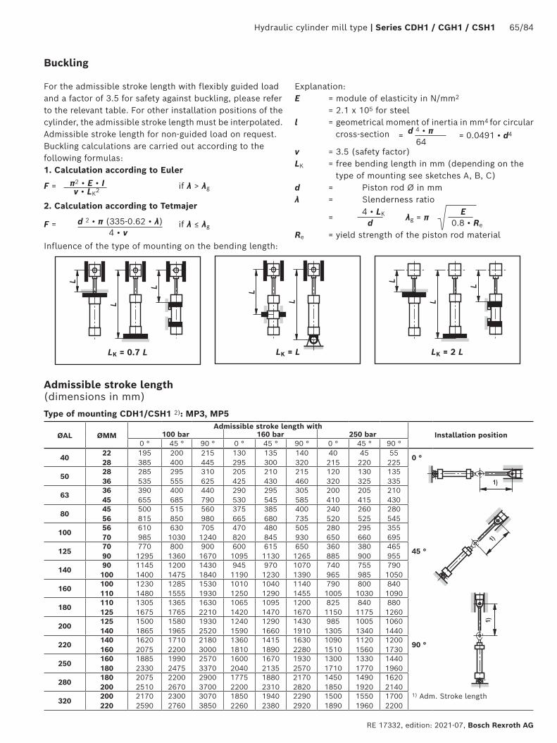
Hydraulic cylinder mill type | Series CDH1 / CGH1 / CSH1 65/84
RE 17332, edition: 2021-07, Bosch Rexroth AG
For the admissible stroke length with flexibly guided load and a factor of 3.5 for safety against buckling, please refer to the relevant table. For other installation positions of the cylinder, the admissible stroke length must be interpolated. Admissible stroke length for non-guided load on request.Buckling calculations are carried out according to the following formulas:1. Calculation according to Euler
2. Calculation according to Tetmajer
π2 • E • IF = if λ > λg ν • LK2
Explanation:E = module of elasticity in N/mm2
= 2.1 x 10⁵ for steell = geometrical moment of inertia in mm4 for circular
cross-section ν = 3.5 (safety factor)LK = free bending length in mm (depending on the
type of mounting see sketches A, B, C)d = Piston rod Ø in mmλ = Slenderness ratio 4 • LK E = λg = π d 0.8 • Re
Re = yield strength of the piston rod material
d 4 • π = = 0.0491 • d4 64
d 2 • π (335-0.62 • λ)F = if λ ≤ λg 4 • ν
LK = L
LK = 2 L
Influence of the type of mounting on the bending length:
LK = 0.7 L
Admissible stroke length (dimensions in mm)
ØAL ØMMAdmissible stroke length with
Installation position100 bar 160 bar 250 bar0 ° 45 ° 90 ° 0 ° 45 ° 90 ° 0 ° 45 ° 90 °
4022 28
195 385
200 400
215 445
130 295
135 300
140 320
40 215
45 220
55 225
0 °
5028 36
285 535
295 555
310 625
205 425
210 430
215 460
120 320
130 325
135 335
6336 45
390 655
400 685
440 790
290 530
295 545
305 585
200 410
205 415
210 430
8045 56
500 815
515 850
560 980
375 665
385 680
400 735
240 520
260 525
280 545
10056 70
610 985
630 1030
705 1240
470 820
480 845
505 930
280 650
295 660
355 695
12570 90
770 1295
800 1360
900 1670
600 1095
615 1130
650 1265
360 885
380 900
465 955
45 °
14090 100
1145 1400
1200 1475
1430 1840
945 1190
970 1230
1070 1390
740 965
755 985
790 1050
160100 110
1230 1480
1285 1555
1530 1930
1010 1250
1040 1290
1140 1455
790 1005
800 1030
840 1090
180110 125
1305 1675
1365 1765
1630 2210
1065 1420
1095 1470
1200 1670
825 1150
840 1175
880 1260
200125 140
1500 1865
1580 1965
1930 2520
1240 1590
1290 1660
1430 1910
985 1305
1005 1340
1060 1440
220140 160
1620 2075
1710 2200
2180 3000
1360 1810
1415 1890
1630 2280
1090 1510
1120 1560
1200 1730
90 °
250160 180
1885 2330
1990 2475
2570 3370
1600 2040
1670 2135
1930 2570
1300 1710
1330 1770
1440 1960
280180 200
2075 2510
2200 2670
2900 3700
1775 2200
1880 2310
2170 2820
1450 1850
1490 1920
1620 2140
320200 220
2170 2590
2300 2760
3070 3850
1850 2260
1940 2380
2290 2920
1500 1890
1550 1960
1700 2200
1) Adm. Stroke length
Type of mounting CDH1/CSH1 2): MP3, MP5
Buckling

66/84 Series CDH1 /CGH1 / CSH1 | Hydraulic cylinder mill type
Bosch Rexroth AG, RE 17332, edition: 2021-07
Admissible stroke length (dimensions in mm)
ØAL ØMMAdmissible stroke length with
Installation position100 bar 160 bar 250 bar0 ° 45 ° 90 ° 0 ° 45 ° 90 ° 0 ° 45 ° 90 °
4022 28
895 1400
915 1415
980 1630
730 1180
735 1205
760 1275
440 970
450 980
510 1010
0 °
5028 36
1180 1785
1200 1855
1280 2160
955 1530
965 1570
995 1695
700 1275
730 1290
780 1340
6336 45
1520 2000
1560 2000
1690 2000
1250 1875
1270 1925
1315 2000
1010 1570
1015 1595
1035 1670
8045 56
1855 2000
1905 2000
2000 2000
1540 2000
1560 2000
1630 2000
1140 1910
1180 1940
1280 2000
10056 70
2250 3000
2320 3000
2500 3000
1880 2770
1910 2860
2010 3000
1300 2360
1360 2400
1580 2550
12570 90
2760 3000
2860 3000
3000 3000
2330 3000
2375 3000
2520 3000
1580 3000
1680 3000
1990 3000
45 °
14090 100
3000 3000
3000 3000
3000 3000
3000 3000
3000 3000
3000 3000
2770 3000
2820 3000
2980 3000
160100 110
3000 3000
3000 3000
3000 3000
3000 3000
3000 3000
3000 3000
2980 3000
3000 3000
3000 3000
180110 125
3000 3000
3000 3000
3000 3000
3000 3000
3000 3000
3000 3000
3000 3000
3000 3000
3000 3000
200125 140
3000 3000
3000 3000
3000 3000
3000 3000
3000 3000
3000 3000
3000 3000
3000 3000
3000 3000
220140 160
5400 6000
5680 6000
6000 6000
4800 5820
4980 6000
5780 6000
4120 5150
4220 5330
4560 6000
90 °
250160 180
6000 6000
6000 6000
6000 6000
5450 6000
5660 6000
6000 6000
4720 5730
4840 5920
5290 6000
280180 200
6000 6000
6000 6000
6000 6000
6000 6000
6000 6000
6000 6000
5270 6000
5420 6000
5970 6000
320200 220
6000 6000
6000 6000
6000 6000
6000 6000
6000 6000
6000 6000
6000 6000
6000 6000
6000 6000
1) Adm. Stroke length
Type of mounting CDH1/CGH1/CSH1 2): MF3
ØAL ØMMAdmissible stroke length with
Installation position100 bar 160 bar 250 bar0 ° 45 ° 90 ° 0 ° 45 ° 90 ° 0 ° 45 ° 90 °
4022 28
325 565
340 590
370 695
245 465
250 475
260 520
105 365
110 370
140 385
0 °
5028 36
455 770
470 805
515 960
350 640
360 660
375 725
220 515
230 525
265 550
6336 45
600 930
620 975
710 1210
475 790
490 820
520 920
350 645
370 660
380 700
8045 56
760 1150
785 1210
895 1495
610 985
625 1020
670 1145
395 810
420 825
495 875
10056 70
905 1370
945 1445
1120 1880
745 1190
765 1235
835 1440
420 995
460 1020
620 1100
12570 90
1175 1815
1225 1920
1460 2560
980 1600
1010 1670
1105 1980
580 1365
620 1400
835 1540
45 °
14090 100
1600 1915
1695 2030
2190 2770
1390 1695
1440 1770
1670 2130
1150 1440
1180 1490
1275 1650
160100 110
1730 2030
1825 2155
2350 2910
1490 1790
1550 1870
1790 2240
1235 1520
1265 1565
1365 1720
180110 125
1850 2295
1950 2440
2510 3000
1590 2030
1655 2130
1900 2570
1310 1730
1340 1785
1450 1980
200125 140
2110 2540
2230 2700
2270 3000
1835 2265
1910 2380
2250 2930
1530 1945
1575 2010
1720 2260
220140 160
2250 2800
2400 2990
3350 4500
1990 2530
2090 2680
2550 3480
1685 2220
1740 2310
1950 2700
90 °
250160 180
2615 3140
2780 3360
3900 5050
2320 2850
2435 3010
3000 3910
1980 2500
2050 2610
2300 3050
280180 200
2850 3370
3050 3610
4400 5550
2550 3070
2680 3250
3370 4300
2190 2700
2270 2820
2600 3330
320200 220
3000 3500
3210 3750
4700 5800
2680 3180
2830 3370
3590 4480
2100 2790
2390 2920
2750 3460
1) Adm. Stroke length
Type of mounting CDH1/CSH1 2): MF4
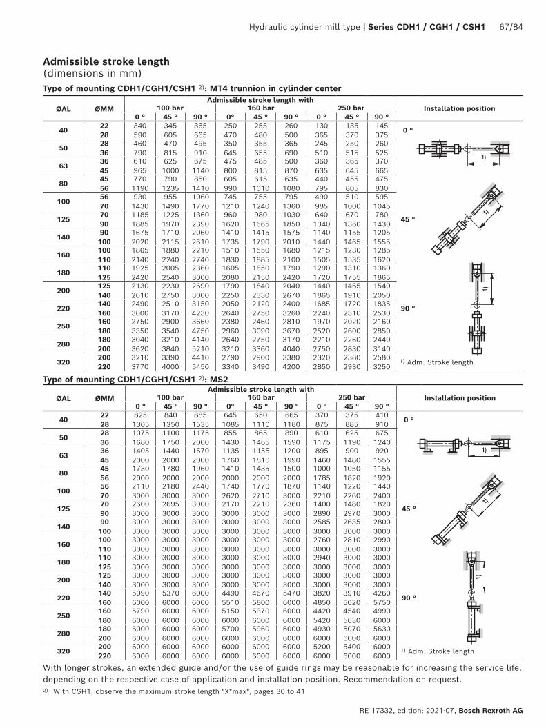
Hydraulic cylinder mill type | Series CDH1 / CGH1 / CSH1 67/84
RE 17332, edition: 2021-07, Bosch Rexroth AG
Admissible stroke length (dimensions in mm)
ØAL ØMMAdmissible stroke length with
Installation position100 bar 160 bar 250 bar0 ° 45 ° 90 ° 0° 45 ° 90 ° 0 ° 45 ° 90 °
4022 28
340 590
345 605
365 665
250 470
255 480
260 500
130 365
135 370
145 375
0 °
5028 36
460 790
470 815
495 910
350 645
355 655
365 690
245 510
250 515
260 525
6336 45
610 965
625 1000
675 1140
475 800
485 815
500 870
360 635
365 645
370 665
8045 56
770 1190
790 1235
850 1410
605 990
615 1010
635 1080
440 795
455 805
475 830
10056 70
930 1430
955 1490
1060 1770
745 1210
755 1240
795 1360
490 985
510 1000
595 1045
12570 90
1185 1885
1225 1970
1360 2390
960 1620
980 1665
1030 1850
640 1340
670 1360
780 1430
45 °
14090 100
1675 2020
1710 2115
2060 2610
1410 1735
1415 1790
1575 2010
1140 1440
1155 1465
1205 1555
160100 110
1805 2140
1880 2240
2210 2740
1510 1830
1550 1885
1680 2100
1215 1505
1230 1535
1285 1620
180110 125
1925 2420
2005 2540
2360 3000
1605 2080
1650 2150
1790 2420
1290 1720
1310 1755
1360 1865
200125 140
2130 2610
2230 2750
2690 3000
1790 2250
1840 2330
2040 2670
1440 1865
1465 1910
1540 2050
220140 160
2490 3000
2510 3170
3150 4230
2050 2640
2120 2750
2400 3260
1685 2240
1720 2310
1835 2530
90 °
250160 180
2750 3350
2900 3540
3660 4750
2380 2960
2460 3090
2810 3670
1970 2520
2020 2600
2160 2850
280180 200
3040 3620
3210 3840
4140 5210
2640 3210
2750 3360
3170 4040
2210 2750
2260 2830
2440 3140
320200 220
3210 3770
3390 4000
4410 5450
2790 3340
2900 3490
3380 4200
2320 2850
2380 2930
2580 3250
1) Adm. Stroke length
Type of mounting CDH1/CGH1/CSH1 2): MT4 trunnion in cylinder center
ØAL ØMMAdmissible stroke length with
Installation position100 bar 160 bar 250 bar0 ° 45 ° 90 ° 0° 45 ° 90 ° 0 ° 45 ° 90 °
4022 28
825 1305
840 1350
885 1535
645 1085
650 1110
665 1180
370 875
375 885
410 910
0 °
5028 36
1075 1680
1100 1750
1175 2000
855 1430
865 1465
890 1590
610 1175
625 1190
675 1240
6336 45
1405 2000
1440 2000
1570 2000
1135 1760
1155 1810
1200 1990
895 1460
900 1480
920 1555
8045 56
1730 2000
1780 2000
1960 2000
1410 2000
1435 2000
1500 2000
1000 1785
1050 1820
1155 1920
10056 70
2110 3000
2180 3000
2440 3000
1740 2620
1770 2710
1870 3000
1140 2210
1220 2260
1440 2400
12570 90
2600 3000
2695 3000
3000 3000
2170 3000
2210 3000
2360 3000
1400 2890
1480 2970
1820 3000
45 °
14090 100
3000 3000
3000 3000
3000 3000
3000 3000
3000 3000
3000 3000
2585 3000
2635 3000
2800 3000
160100 110
3000 3000
3000 3000
3000 3000
3000 3000
3000 3000
3000 3000
2760 3000
2810 3000
2990 3000
180110 125
3000 3000
3000 3000
3000 3000
3000 3000
3000 3000
3000 3000
2940 3000
3000 3000
3000 3000
200125 140
3000 3000
3000 3000
3000 3000
3000 3000
3000 3000
3000 3000
3000 3000
3000 3000
3000 3000
220140 160
5090 6000
5370 6000
6000 6000
4490 5510
4670 5800
5470 6000
3820 4850
3910 5020
4260 5750
90 °
250160 180
5790 6000
6000 6000
6000 6000
5150 6000
5370 6000
6000 6000
4420 5420
4540 5630
4990 6000
280180 200
6000 6000
6000 6000
6000 6000
5700 6000
5960 6000
6000 6000
4930 6000
5070 6000
5630 6000
320200 220
6000 6000
6000 6000
6000 6000
6000 6000
6000 6000
6000 6000
5200 6000
5400 6000
6000 6000
1) Adm. Stroke length
Type of mounting CDH1/CGH1/CSH1 2): MS2
With longer strokes, an extended guide and/or the use of guide rings may be reasonable for increasing the service life, depending on the respective case of application and installation position. Recommendation on request.2) With CSH1, observe the maximum stroke length "X*max", pages 30 to 41

68/84 Series CDH1 /CGH1 / CSH1 | Hydraulic cylinder mill type
Bosch Rexroth AG, RE 17332, edition: 2021-07
Formulas: m = moved mass in kg v = stroke velocity in m/s kv = see table page 69
Extension for CDH1 and CSH1
Retraction for CDH1, CGH1 and CSH1; extension for CGH1
pS = system pressure in bar A1 = piston area in cm2 (see page 14) A3 = annulus area in cm2 (see page 14) α = angle to the horizontal in degree
mDm = ; 10K K = kv (0.5–v)
m • 9.81 • sinαDp = pS – A1 • 10
m • 9.81 • sinαDp = pS + A3 • 10
Damping length With cylinder strokes within the damping lengths, restrictions with regard to velocity / cycle time are possible. We recommend minimum stroke greater than the damping length plus 10 mm!
ØAL mm 40 50 63 80 100 125 140 160 180 200 220 250 280 320
Head side 21 20 23 25 25 25 33 33 37 37 76 81 86 90
Base side 21 20 23 25 25 25 33 33 37 37 76 81 86 90
End position cushioning: The objective is to reduce the velocity of a moved mass, the center of gravity of which lies on the cylinder axis, to a level at which neither the cylinder nor the machine into which the cylinder is installed is damaged. For velocities above 20 mm/s, we recommend the use of an end position cushioning feature, which absorbs energy without requiring the use of additional equipment. It must, however, always be checked whether end position cushioning is also required for lower velocities with large masses.
Damping capacity: When decelerating masses via end position cushioning, the structural-inherent damping capacity must not be exceeded. Cylinders with end position cushioning can achieve their full damping capacity only over the entire stroke length.With the adjustable end position cushioning version "E", a throttle valve is additionally provided when compared with version "D". End position cushioning version "E" allows cycle times to be optimized. The max. damping
capacity can only be achieved when the throttle valve is closed.The calculation depends on the factors mass, velocity, system pressure and installation position. For this reason, mass and velocity are used to determine the characteristic Dm and system pressure and installation position to determine the characteristic Dp. These two characteristics are used for verifying the admissible damping capacity in the "damping capacity" diagram. The intersection point of the characteristics Dm and Dp must always be below the damping capacity curve of the selected cylinder. The values in the diagrams refer to an average oil temperature of +45 to +65 °C with the throttle valve being closed.For special applications with very short stroke times, high velocities or large masses, cylinders with special end position cushioning versions can be offered on request.When fixed or adjustable stops are used, special measures must be taken!
End position cushioning
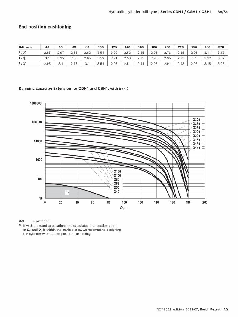
Hydraulic cylinder mill type | Series CDH1 / CGH1 / CSH1 69/84
RE 17332, edition: 2021-07, Bosch Rexroth AG
1)
ØAL mm 40 50 63 80 100 125 140 160 180 200 220 250 280 320
kv ① 2.85 2.97 2.56 2.82 3.51 3.02 2.53 2.65 2.91 2.76 2.85 2.95 3.11 3.13
kv ② 3.1 3.25 2.85 2.85 3.52 2.91 2.53 2.93 2.95 2.95 2.93 3.1 3.12 3.07
kv ③ 2.95 3.1 2.73 3.1 3.51 2.95 2.51 2.91 2.95 2.91 2.93 2.93 3.15 3.25
Damping capacity: Extension for CDH1 and CSH1, with kv ①
Dp →
ØAL = piston Ø1) If with standard applications the calculated intersection point
of Dm and Dp is within the marked area, we recommend designing the cylinder without end position cushioning.
End position cushioning
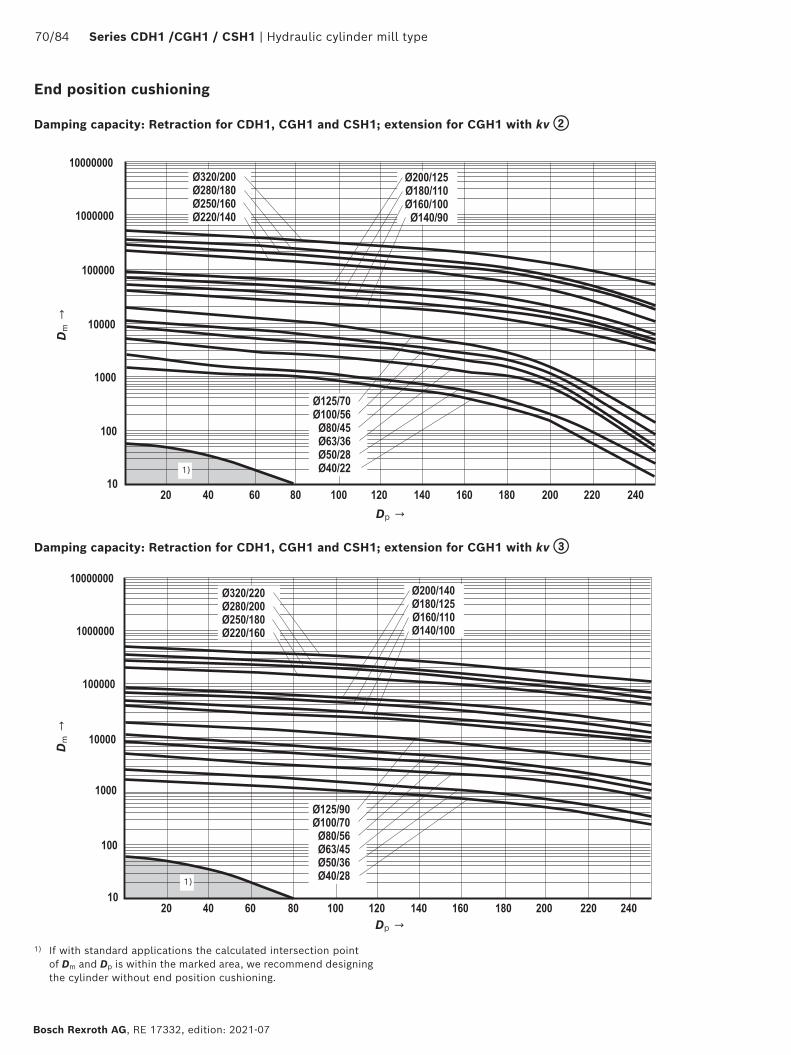
70/84 Series CDH1 /CGH1 / CSH1 | Hydraulic cylinder mill type
Bosch Rexroth AG, RE 17332, edition: 2021-07
End position cushioning
1)
1)
Damping capacity: Retraction for CDH1, CGH1 and CSH1; extension for CGH1 with kv ②
Dm →
Dp →
Dm →
Dp →
Damping capacity: Retraction for CDH1, CGH1 and CSH1; extension for CGH1 with kv ③
1) If with standard applications the calculated intersection point of Dm and Dp is within the marked area, we recommend designing the cylinder without end position cushioning.
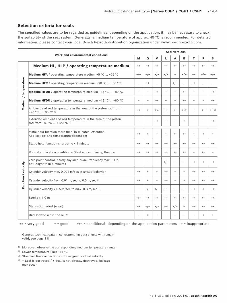
Hydraulic cylinder mill type | Series CDH1 / CGH1 / CSH1 71/84
RE 17332, edition: 2021-07, Bosch Rexroth AG
Selection criteria for seals
Work and environmental conditionsSeal versions
M G V L A B T R S
Med
ium
/ t
empe
ratu
re
Medium HL, HLP / operating temperature medium ++ ++ ++ ++ ++ ++ ++ ++ ++
Medium HFA / operating temperature medium +5 °C … +55 °C +/– +/– +/– +/– + +/– ++ +/– +/–
Medium HFC / operating temperature medium –20 °C … +60 °C – ++ – – +/– – ++ – –
Medium HFDR / operating temperature medium –15 °C … +80 °C – – ++ – – ++ – – ++
Medium HFDU / operating temperature medium –15 °C … +80 °C – – ++ – – ++ – – ++
Ambient and rod temperature in the area of the piston rod from –20 °C … +80 °C 1) ++ + + 2) ++ ++ + 2) + ++ ++ 2)
Extended ambient and rod temperature in the area of the piston rod from +80 °C … +120 °C 1) – – ++ – – + – – ++
Func
tion
/ v
eloc
ity.
..
static hold function more than 10 minutes: Attention! Application- and temperature-dependent
++ + + + ++ ++ + + +
Static hold function short-time < 1 minute ++ ++ ++ ++ ++ ++ ++ ++ ++
Robust application conditions: Steel works, mining, thin ice ++ ++ ++ ++ ++ ++ – ++ –
Zero point control, hardly any amplitude, frequency max. 5 Hz, not longer than 5 minutes
– – – +/– – – ++ + ++
Cylinder velocity min. 0.001 m/sec stick-slip behavior ++ + + ++ – – ++ ++ ++
Cylinder velocity from 0.01 m/sec to 0.5 m/sec 3) ++ + + ++ + + ++ ++ ++
Cylinder velocity > 0.5 m/sec to max. 0.8 m/sec 3) – +/– +/– ++ – – ++ + ++
Stroke > 1.0 m +/– ++ ++ ++ ++ ++ ++ ++ ++
Standstill period (wear) ++ +/– +/– ++ +/– – ++ ++ ++
Undissolved air in the oil 4) – + + + – – + + +
++ = very good + = good +/– = conditional, depending on the application parameters – = inappropriate
General technical data in corresponding data sheets will remain valid, see page 11!
1) Moreover, observe the corresponding medium temperature range2) Lower temperature limit –15 °C3) Standard line connections not designed for that velocity4) – Seal is destroyed / + Seal is not directly destroyed, leakage
may occur
The specified values are to be regarded as guidelines; depending on the application, it may be necessary to check the suitability of the seal system. Generally, a medium temperature of approx. 40 °C is recommended. For detailed information, please contact your local Bosch Rexroth distribution organization under www.boschrexroth.com.
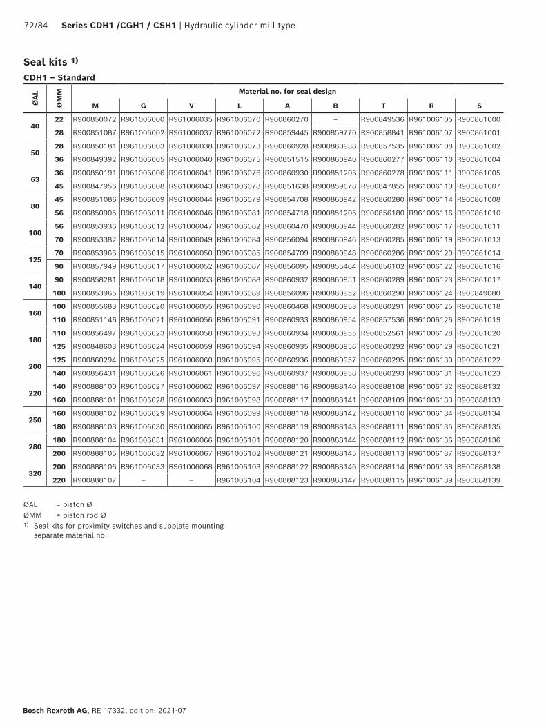
72/84 Series CDH1 /CGH1 / CSH1 | Hydraulic cylinder mill type
Bosch Rexroth AG, RE 17332, edition: 2021-07
CDH1 – Standard
ØA
L
ØM
M
Material no. for seal design
M G V L A B T R S
4022 R900850072 R961006000 R961006035 R961006070 R900860270 ‒ R900849536 R961006105 R900861000
28 R900851087 R961006002 R961006037 R961006072 R900859445 R900859770 R900858841 R961006107 R900861001
5028 R900850181 R961006003 R961006038 R961006073 R900860928 R900860938 R900857535 R961006108 R900861002
36 R900849392 R961006005 R961006040 R961006075 R900851515 R900860940 R900860277 R961006110 R900861004
6336 R900850191 R961006006 R961006041 R961006076 R900860930 R900851206 R900860278 R961006111 R900861005
45 R900847956 R961006008 R961006043 R961006078 R900851638 R900859678 R900847855 R961006113 R900861007
8045 R900851086 R961006009 R961006044 R961006079 R900854708 R900860942 R900860280 R961006114 R900861008
56 R900850905 R961006011 R961006046 R961006081 R900854718 R900851205 R900856180 R961006116 R900861010
10056 R900853936 R961006012 R961006047 R961006082 R900860470 R900860944 R900860282 R961006117 R900861011
70 R900853382 R961006014 R961006049 R961006084 R900856094 R900860946 R900860285 R961006119 R900861013
12570 R900853966 R961006015 R961006050 R961006085 R900854709 R900860948 R900860286 R961006120 R900861014
90 R900857949 R961006017 R961006052 R961006087 R900856095 R900855464 R900856102 R961006122 R900861016
14090 R900858281 R961006018 R961006053 R961006088 R900860932 R900860951 R900860289 R961006123 R900861017
100 R900853965 R961006019 R961006054 R961006089 R900856096 R900860952 R900860290 R961006124 R900849080
160100 R900855683 R961006020 R961006055 R961006090 R900860468 R900860953 R900860291 R961006125 R900861018
110 R900851146 R961006021 R961006056 R961006091 R900860933 R900860954 R900857536 R961006126 R900861019
180110 R900856497 R961006023 R961006058 R961006093 R900860934 R900860955 R900852561 R961006128 R900861020
125 R900848603 R961006024 R961006059 R961006094 R900860935 R900860956 R900860292 R961006129 R900861021
200125 R900860294 R961006025 R961006060 R961006095 R900860936 R900860957 R900860295 R961006130 R900861022
140 R900856431 R961006026 R961006061 R961006096 R900860937 R900860958 R900860293 R961006131 R900861023
220140 R900888100 R961006027 R961006062 R961006097 R900888116 R900888140 R900888108 R961006132 R900888132
160 R900888101 R961006028 R961006063 R961006098 R900888117 R900888141 R900888109 R961006133 R900888133
250160 R900888102 R961006029 R961006064 R961006099 R900888118 R900888142 R900888110 R961006134 R900888134
180 R900888103 R961006030 R961006065 R961006100 R900888119 R900888143 R900888111 R961006135 R900888135
280180 R900888104 R961006031 R961006066 R961006101 R900888120 R900888144 R900888112 R961006136 R900888136
200 R900888105 R961006032 R961006067 R961006102 R900888121 R900888145 R900888113 R961006137 R900888137
320200 R900888106 R961006033 R961006068 R961006103 R900888122 R900888146 R900888114 R961006138 R900888138
220 R900888107 ‒ ‒ R961006104 R900888123 R900888147 R900888115 R961006139 R900888139
ØAL = piston ØØMM = piston rod Ø1) Seal kits for proximity switches and subplate mounting
separate material no.
Seal kits 1)

Hydraulic cylinder mill type | Series CDH1 / CGH1 / CSH1 73/84
RE 17332, edition: 2021-07, Bosch Rexroth AG
Seal kits 1)Ø
AL
ØM
M
Material no. for seal design
M G V L A B T R S
4022 R900867251 R961006221 R961006256 R961006291 R900866746 ‒ R900868888 R961006326 R900868942
28 R900867252 R961006223 R961006258 R961006293 R900866747 R900867133 R900868889 R961006328 R900868943
5028 R900867253 R961006224 R961006259 R961006294 R900866748 R900867134 R900868890 R961006329 R900868944
36 R900864930 R961006226 R961006261 R961006296 R900866750 R900867136 R900868892 R961006331 R900868946
6336 R900867260 R961006227 R961006262 R961006297 R900866751 R900867137 R900868893 R961006332 R900868947
45 R900867262 R961006229 R961006264 R961006299 R900866753 R900867139 R900868895 R961006334 R900868949
8045 R900867263 R961006230 R961006265 R961006300 R900866754 R900867140 R900868896 R961006335 R900868950
56 R900867265 R961006232 R961006267 R961006302 R900866756 R900867142 R900868898 R961006337 R900868952
10056 R900867266 R961006233 R961006268 R961006303 R900866757 R900867143 R900868899 R961006338 R900868953
70 R900867268 R961006235 R961006270 R961006305 R900866759 R900867146 R900868901 R961006340 R900868955
12570 R900867269 R961006236 R961006271 R961006306 R900866760 R900867147 R900868902 R961006341 R900867906
90 R900867270 R961006238 R961006273 R961006308 R900866762 R900867149 R900868904 R961006343 R900868957
14090 R900867271 R961006239 R961006274 R961006309 R900866763 R900867150 R900868905 R961006344 R900868958
100 R900867272 R961006240 R961006275 R961006310 R900866764 R900867151 R900868906 R961006345 R900868959
160100 R900867273 R961006241 R961006276 R961006311 R900866765 R900867152 R900868907 R961006346 R900868960
110 R900867274 R961006242 R961006277 R961006312 R900866766 R900867153 R900868908 R961006347 R900868961
180110 R900867275 R961006244 R961006279 R961006314 R900866767 R900867154 R900868909 R961006349 R900868962
125 R900867276 R961006245 R961006280 R961006315 R900866768 R900867155 R900868910 R961006350 R900868963
200125 R900867277 R961006246 R961006281 R961006316 R900866769 R900867156 R900868911 R961006351 R900868964
140 R900867278 R961006247 R961006282 R961006317 R900866770 R900867157 R900868912 R961006352 R900868965
220140 R900888020 R961006248 R961006283 R961006318 R900888036 R900888060 R900888028 R961006353 R900888052
160 R900888021 R961006249 R961006284 R961006319 R900888037 R900888061 R900888029 R961006354 R900888053
250160 R900888022 R961006250 R961006285 R961006320 R900888038 R900888062 R900888030 R961006355 R900888054
180 R900888023 R961006251 R961006286 R961006321 R900888039 R900888063 R900888031 R961006356 R900888055
280180 R900888024 R961006252 R961006287 R961006322 R900888040 R900888064 R900888032 R961006357 R900888056
200 R900888025 R961006253 R961006288 R961006323 R900888041 R900888065 R900888033 R961006358 R900888057
320200 R900888026 R961006254 R961006289 R961006324 R900888042 R900888066 R900888034 R961006359 R900888058
220 R900888027 ‒ ‒ R961006325 R900888043 R900888067 R900888035 R961006360 R900888059
CGH1 – Standard
ØAL = piston ØØMM = piston rod Ø1) Seal kits for proximity switches and subplate mounting
separate material no.

74/84 Series CDH1 /CGH1 / CSH1 | Hydraulic cylinder mill type
Bosch Rexroth AG, RE 17332, edition: 2021-07
Seal kits 1)
CDH1 – Standard + additional option F
ØA
L
ØM
M
Material no. for seal design
M+F G+F V+F T+F R+F S+F
4022 R900861024 R961006140 R961006167 R900861049 R961006194 R900861099
28 R900861025 R961006142 R961006169 R900861050 R961006196 R900861100
5028 R900861026 R961006143 R961006170 R900861051 R961006197 R900861101
36 R900861028 R961006145 R961006172 R900861053 R961006199 R900861103
6336 R900861029 R961006146 R961006173 R900861054 R961006200 R900861104
45 R900861031 R961006148 R961006175 R900861056 R961006202 R900861106
8045 R900861032 R961006149 R961006176 R900861057 R961006203 R900861107
56 R900861034 R961006151 R961006178 R900861059 R961006205 R900861109
10056 R900861035 R961006152 R961006179 R900861060 R961006206 R900861112
70 R900861037 R961006154 R961006181 R900861062 R961006208 R900861115
12570 R900861038 R961006155 R961006182 R900861063 R961006209 R900861117
90 R900861040 R961006157 R961006184 R900861065 R961006211 R900861122
14090 R900861041 R961006158 R961006185 R900861066 R961006212 R900861124
100 R900861042 R961006159 R961006186 R900861067 R961006213 R900861126
160100 R900861043 R961006160 R961006187 R900861068 R961006214 R900861128
110 R900861044 R961006161 R961006188 R900861069 R961006215 R900861130
180110 R900861045 R961006163 R961006190 R900861070 R961006217 R900861133
125 R900861046 R961006164 R961006191 R900861071 R961006218 R900861135
200125 R900861047 R961006165 R961006192 R900861072 R961006219 R900861142
140 R900861048 R961006166 R961006193 R900861073 R961006220 R900861143
CGH1 – Standard + additional option F
ØA
L
ØM
M
Material no. for seal design
M+F G+F V+F T+F R+F S+F
4022 R900868998 R961006361 R961006388 R900869025 R961006415 R900869092
28 R900868999 R961006363 R961006390 R900869026 R961006417 R900869093
5028 R900869000 R961006364 R961006391 R900869027 R961006418 R900869094
36 R900869002 R961006366 R961006393 R900869029 R961006420 R900869096
6336 R900869003 R961006367 R961006394 R900869030 R961006421 R900869097
45 R900869005 R961006369 R961006396 R900869032 R961006423 R900869099
8045 R900869006 R961006370 R961006397 R900869033 R961006424 R900869100
56 R900869008 R961006372 R961006399 R900869035 R961006426 R900869102
10056 R900869009 R961006373 R961006400 R900869036 R961006427 R900869103
70 R900869013 R961006375 R961006402 R900869038 R961006429 R900869105
12570 R900869014 R961006376 R961006403 R900869039 R961006430 R900869106
90 R900869016 R961006378 R961006405 R900869041 R961006432 R900869108
14090 R900869017 R961006379 R961006406 R900869042 R961006433 R900869109
100 R900869018 R961006380 R961006407 R900869043 R961006434 R900869110
160100 R900869019 R961006381 R961006408 R900869044 R961006435 R900869111
110 R900869020 R961006382 R961006409 R900869045 R961006436 R900869112
180110 R900869021 R961006384 R961006411 R900869046 R961006438 R900869113
125 R900869022 R961006385 R961006412 R900869047 R961006439 R900869114
200125 R900869023 R961006386 R961006413 R900869048 R961006440 R900869115
140 R900869024 R961006387 R961006414 R900869049 R961006441 R900869116
ØAL = piston ØØMM = piston rod Ø
1) Seal kits for proximity switches and subplate mounting separate material no.
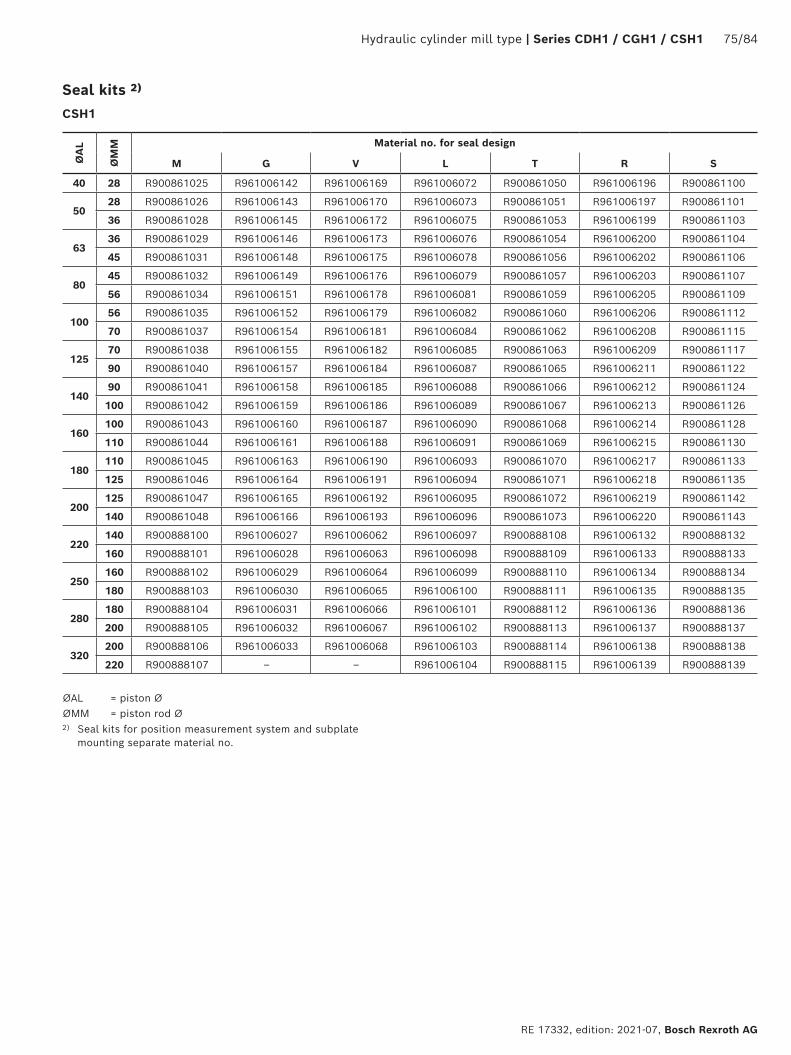
Hydraulic cylinder mill type | Series CDH1 / CGH1 / CSH1 75/84
RE 17332, edition: 2021-07, Bosch Rexroth AG
Seal kits 2)
CSH1
ØA
L
ØM
M
Material no. for seal design
M G V L T R S
40 28 R900861025 R961006142 R961006169 R961006072 R900861050 R961006196 R900861100
5028 R900861026 R961006143 R961006170 R961006073 R900861051 R961006197 R900861101
36 R900861028 R961006145 R961006172 R961006075 R900861053 R961006199 R900861103
6336 R900861029 R961006146 R961006173 R961006076 R900861054 R961006200 R900861104
45 R900861031 R961006148 R961006175 R961006078 R900861056 R961006202 R900861106
8045 R900861032 R961006149 R961006176 R961006079 R900861057 R961006203 R900861107
56 R900861034 R961006151 R961006178 R961006081 R900861059 R961006205 R900861109
10056 R900861035 R961006152 R961006179 R961006082 R900861060 R961006206 R900861112
70 R900861037 R961006154 R961006181 R961006084 R900861062 R961006208 R900861115
12570 R900861038 R961006155 R961006182 R961006085 R900861063 R961006209 R900861117
90 R900861040 R961006157 R961006184 R961006087 R900861065 R961006211 R900861122
14090 R900861041 R961006158 R961006185 R961006088 R900861066 R961006212 R900861124
100 R900861042 R961006159 R961006186 R961006089 R900861067 R961006213 R900861126
160100 R900861043 R961006160 R961006187 R961006090 R900861068 R961006214 R900861128
110 R900861044 R961006161 R961006188 R961006091 R900861069 R961006215 R900861130
180110 R900861045 R961006163 R961006190 R961006093 R900861070 R961006217 R900861133
125 R900861046 R961006164 R961006191 R961006094 R900861071 R961006218 R900861135
200125 R900861047 R961006165 R961006192 R961006095 R900861072 R961006219 R900861142
140 R900861048 R961006166 R961006193 R961006096 R900861073 R961006220 R900861143
220140 R900888100 R961006027 R961006062 R961006097 R900888108 R961006132 R900888132
160 R900888101 R961006028 R961006063 R961006098 R900888109 R961006133 R900888133
250160 R900888102 R961006029 R961006064 R961006099 R900888110 R961006134 R900888134
180 R900888103 R961006030 R961006065 R961006100 R900888111 R961006135 R900888135
280180 R900888104 R961006031 R961006066 R961006101 R900888112 R961006136 R900888136
200 R900888105 R961006032 R961006067 R961006102 R900888113 R961006137 R900888137
320200 R900888106 R961006033 R961006068 R961006103 R900888114 R961006138 R900888138
220 R900888107 ‒ ‒ R961006104 R900888115 R961006139 R900888139
ØAL = piston ØØMM = piston rod Ø2) Seal kits for position measurement system and subplate
mounting separate material no.
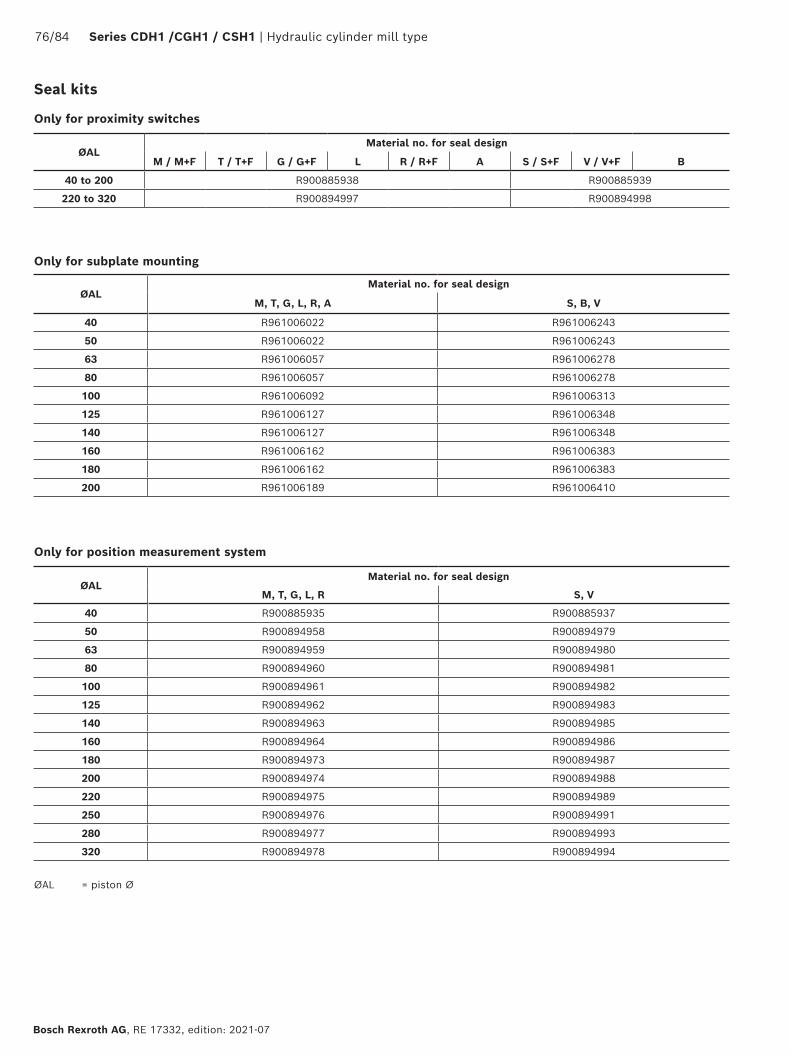
76/84 Series CDH1 /CGH1 / CSH1 | Hydraulic cylinder mill type
Bosch Rexroth AG, RE 17332, edition: 2021-07
Only for proximity switches
ØAL Material no. for seal design
M / M+F T / T+F G / G+F L R / R+F A S / S+F V / V+F B
40 to 200 R900885938 R900885939
220 to 320 R900894997 R900894998
ØALMaterial no. for seal design
M, T, G, L, R, A S, B, V
40 R961006022 R961006243
50 R961006022 R961006243
63 R961006057 R961006278
80 R961006057 R961006278
100 R961006092 R961006313
125 R961006127 R961006348
140 R961006127 R961006348
160 R961006162 R961006383
180 R961006162 R961006383
200 R961006189 R961006410
Only for subplate mounting
Only for position measurement system
ØALMaterial no. for seal design
M, T, G, L, R S, V
40 R900885935 R900885937
50 R900894958 R900894979
63 R900894959 R900894980
80 R900894960 R900894981
100 R900894961 R900894982
125 R900894962 R900894983
140 R900894963 R900894985
160 R900894964 R900894986
180 R900894973 R900894987
200 R900894974 R900894988
220 R900894975 R900894989
250 R900894976 R900894991
280 R900894977 R900894993
320 R900894978 R900894994
ØAL = piston Ø
Seal kits

Hydraulic cylinder mill type | Series CDH1 / CGH1 / CSH1 77/84
RE 17332, edition: 2021-07, Bosch Rexroth AG
Tightening torques
1 2
3
Series Piston Ø Piston rod Ø Screw Quantity Quality class Tightening torque
CDH1 / CGH1 160100
M10 16 10.9 60 Nm110
CDH1 / CGH1 180110
M12 16 10.9 80 Nm125
CDH1 / CGH1 200125
M12 16 10.9 90 Nm140
CDH1 / CGH1 220140
M1216
10.9 90 Nm160 24
CDH1 / CGH1 250160
M12 24 10.9 90 Nm180
CDH1 / CGH1 280180
M12 24 10.9 90 Nm200
CDH1 / CGH1 320200 M12 24
10.990 Nm
220 M16 16 230 Nm
Screws: Seal cover (item 3)
Series Piston Ø Screw Quantity Quality class Tightening torque
CDH1 / CGH1 / CSH1 40 M8 4 10.9 23 Nm
CDH1 / CGH1 / CSH1 50 M8 8 10.9 20 Nm
CDH1 / CGH1 / CSH1 63 M8 8 10.9 30 Nm
CDH1 / CGH1 / CSH1 80 M10 8 10.9 55 Nm
CDH1 / CGH1 / CSH1 100 M12 8 10.9 100 Nm
CDH1 / CGH1 / CSH1 125 M16 8 10.9 200 Nm
CDH1 / CGH1 / CSH1 140 M16 12 10.9 170 Nm
CDH1 / CGH1 / CSH1 160 M16 12 10.9 220 Nm
CDH1 / CGH1 / CSH1 180 M20 12 10.9 350 Nm
CDH1 / CGH1 / CSH1 200 M20 12 10.9 410 Nm
CDH1 / CGH1 / CSH1 220 M20 16 10.9 460 Nm
CDH1 / CGH1 / CSH1 250 M24 16 10.9 700 Nm
CDH1 / CGH1 / CSH1 280 M24 16 10.9 800 Nm
CDH1 / CGH1 / CSH1 320 M30 16 10.9 1500 Nm
Screws: Head and base (item 1 and 2)
Only with seal design "A" and "B"
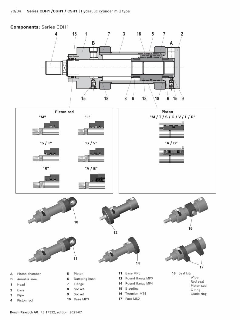
78/84 Series CDH1 /CGH1 / CSH1 | Hydraulic cylinder mill type
Bosch Rexroth AG, RE 17332, edition: 2021-07
Components: Series CDH1
Piston rod Piston"M"
"R"
"S / T"
"M / T / S / G / V / L / R"
"A / B"
A Piston chamber
B Annulus area
1 Head
2 Base
3 Pipe
4 Piston rod
5 Piston
6 Damping bush
7 Flange
8 Socket
9 Socket
10 Base MP3
11 Base MP5
12 Round flange MF3
14 Round flange MF4
15 Bleeding
16 Trunnion MT4
17 Foot MS2
18 Seal kit: Wiper Rod seal Piston seal O-ring Guide ring
"L"
"G / V"
"A / B"
10
1216
1114
17

Hydraulic cylinder mill type | Series CDH1 / CGH1 / CSH1 79/84
RE 17332, edition: 2021-07, Bosch Rexroth AG
18 Seal kit: Wiper Rod seal Piston seal O-ring Guide ring
Components: Series CGH1
1216 17
B1 Annulus area 1B2 Annulus area 2
1 Head3 Pipe4 Piston rod5 Piston6 Damping bush7 Flange8 Socket
12 Round flange MF315 Bleeding16 Trunnion MT417 Foot MS218 Seal kit:
Wiper Rod seal Piston seal O-ring Guide ring
Piston rod Piston"M / T / S / G / V / L / R"
"A / B"
"M"
"R"
"S / T"
"L"
"G / V"
"A / B"
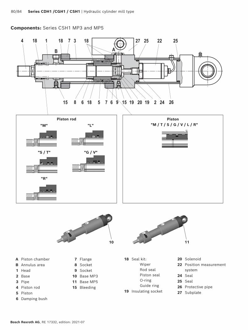
80/84 Series CDH1 /CGH1 / CSH1 | Hydraulic cylinder mill type
Bosch Rexroth AG, RE 17332, edition: 2021-07
Components: Series CSH1 MP3 and MP5
10 11
Piston rod Piston"M / T / S / G / V / L / R"
A Piston chamberB Annulus area1 Head2 Base3 Pipe4 Piston rod5 Piston6 Damping bush
7 Flange8 Socket9 Socket
10 Base MP311 Base MP515 Bleeding
18 Seal kit: Wiper Rod seal Piston seal O-ring Guide ring
19 Insulating socket
20 Solenoid22 Position measurement
system24 Seal25 Seal26 Protective pipe27 Subplate
"M"
"R"
"S / T"
"L"
"G / V"
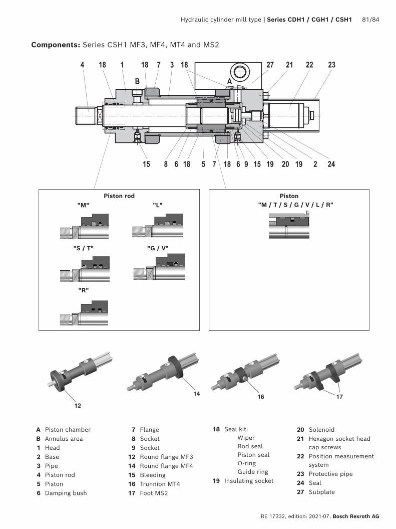
Hydraulic cylinder mill type | Series CDH1 / CGH1 / CSH1 81/84
RE 17332, edition: 2021-07, Bosch Rexroth AG
12
14 16 17
Piston rod Piston"M / T / S / G / V / L / R"
A Piston chamberB Annulus area1 Head2 Base3 Pipe4 Piston rod5 Piston6 Damping bush
7 Flange8 Socket9 Socket
12 Round flange MF314 Round flange MF415 Bleeding16 Trunnion MT417 Foot MS2
18 Seal kit: Wiper Rod seal Piston seal O-ring Guide ring
19 Insulating socket
20 Solenoid21 Hexagon socket head
cap screws22 Position measurement
system23 Protective pipe24 Seal27 Subplate
"M"
"R"
"S / T"
"L"
"G / V"
Components: Series CSH1 MF3, MF4, MT4 and MS2
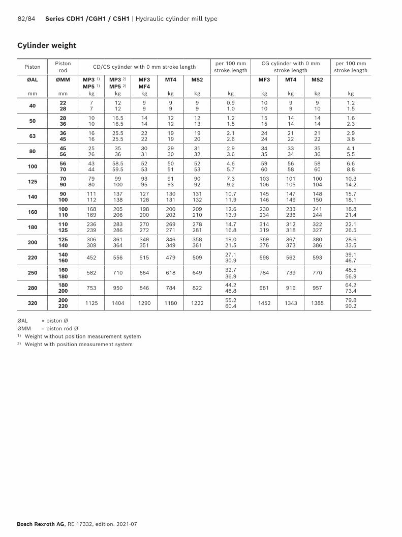
82/84 Series CDH1 /CGH1 / CSH1 | Hydraulic cylinder mill type
Bosch Rexroth AG, RE 17332, edition: 2021-07
PistonPiston
rodCD/CS cylinder with 0 mm stroke length
per 100 mm stroke length
CG cylinder with 0 mm stroke length
per 100 mm stroke length
ØAL
mm
ØMM
mm
MP3 1) MP5 1)
kg
MP3 2) MP5 2)
kg
MF3 MF4 kg
MT4
kg
MS2
kg
kg
MF3
kg
MT4
kg
MS2
kg
kg
40 22 7 12 9 9 9 0.9 10 9 9 1.228 7 12 9 9 9 1.0 10 9 10 1.5
50 28 10 16.5 14 12 12 1.2 15 14 14 1.636 10 16.5 14 12 13 1.5 15 14 14 2.3
63 36 16 25.5 22 19 19 2.1 24 21 21 2.945 16 25.5 22 19 20 2.6 24 22 22 3.8
80 45 25 35 30 29 31 2.9 34 33 35 4.156 26 36 31 30 32 3.6 35 34 36 5.5
100 56 43 58.5 52 50 52 4.6 59 56 58 6.670 44 59.5 53 51 53 5.7 60 58 60 8.8
125 70 79 99 93 91 90 7.3 103 101 100 10.390 80 100 95 93 92 9.2 106 105 104 14.2
140 90 111 137 127 130 131 10.7 145 147 148 15.7100 112 138 128 131 132 11.9 146 149 150 18.1
160 100 168 205 198 200 209 12.6 230 233 241 18.8110 169 206 200 202 210 13.9 234 236 244 21.4
180 110 236 283 270 269 278 14.7 314 312 322 22.1125 239 286 272 271 281 16.8 319 318 327 26.5
200 125 306 361 348 346 358 19.0 369 367 380 28.6140 309 364 351 349 361 21.5 376 373 386 33.5
220 140 452 556 515 479 509 27.1 598 562 593 39.1160 30.9 46.7
250 160 582 710 664 618 649 32.7 784 739 770 48.5180 36.9 56.9
280 180 753 950 846 784 822 44.2 981 919 957 64.2200 48.8 73.4
320 200 1125 1404 1290 1180 1222 55.2 1452 1343 1385 79.8220 60.4 90.2
ØAL = piston ØØMM = piston rod Ø1) Weight without position measurement system2) Weight with position measurement system
Cylinder weight
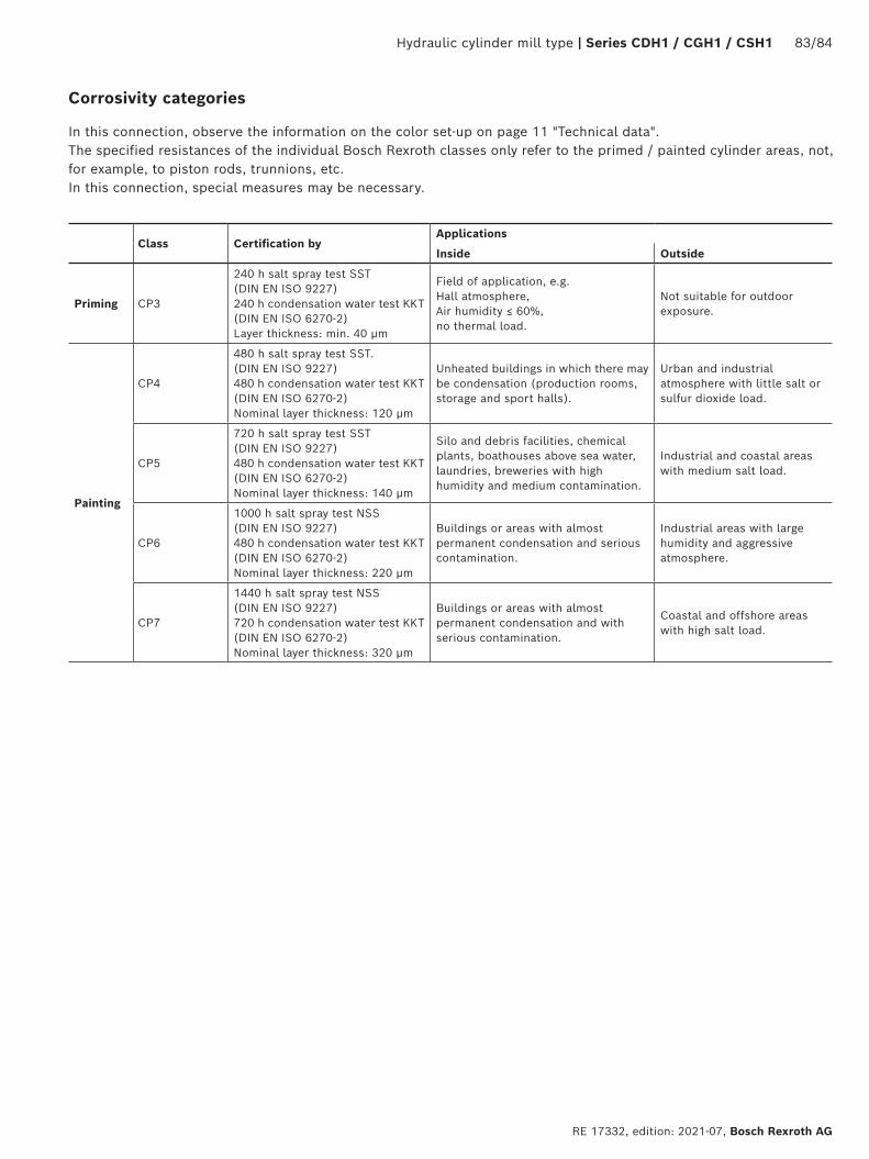
Hydraulic cylinder mill type | Series CDH1 / CGH1 / CSH1 83/84
RE 17332, edition: 2021-07, Bosch Rexroth AG
In this connection, observe the information on the color set-up on page 11 "Technical data". The specified resistances of the individual Bosch Rexroth classes only refer to the primed / painted cylinder areas, not, for example, to piston rods, trunnions, etc. In this connection, special measures may be necessary.
Class Certification byApplications
Inside Outside
Priming CP3
240 h salt spray test SST (DIN EN ISO 9227) 240 h condensation water test KKT (DIN EN ISO 6270-2) Layer thickness: min. 40 μm
Field of application, e.g. Hall atmosphere, Air humidity ≤ 60%, no thermal load.
Not suitable for outdoor exposure.
Painting
CP4
480 h salt spray test SST. (DIN EN ISO 9227) 480 h condensation water test KKT (DIN EN ISO 6270-2) Nominal layer thickness: 120 μm
Unheated buildings in which there may be condensation (production rooms, storage and sport halls).
Urban and industrial atmosphere with little salt or sulfur dioxide load.
CP5
720 h salt spray test SST (DIN EN ISO 9227) 480 h condensation water test KKT (DIN EN ISO 6270-2) Nominal layer thickness: 140 μm
Silo and debris facilities, chemical plants, boathouses above sea water, laundries, breweries with high humidity and medium contamination.
Industrial and coastal areas with medium salt load.
CP6
1000 h salt spray test NSS (DIN EN ISO 9227) 480 h condensation water test KKT (DIN EN ISO 6270-2) Nominal layer thickness: 220 μm
Buildings or areas with almost permanent condensation and serious contamination.
Industrial areas with large humidity and aggressive atmosphere.
CP7
1440 h salt spray test NSS (DIN EN ISO 9227) 720 h condensation water test KKT (DIN EN ISO 6270-2) Nominal layer thickness: 320 μm
Buildings or areas with almost permanent condensation and with serious contamination.
Coastal and offshore areas with high salt load.
Corrosivity categories

Bosch Rexroth AG, RE 17332, edition: 2021-07
84/84 Series CDH1 /CGH1 / CSH1 | Hydraulic cylinder mill type
Bosch Rexroth AG Industrial HydraulicsZum Eisengießer 197816 Lohr am Main, Germany Phone +49 (0) 93 52 / 40 30 20 [email protected] www.boschrexroth.de
© All rights reserved to Bosch Rexroth AG, also regarding any disposal, exploitation, reproduction, editing, distribution, as well as in the event of applications for industrial property rights.The data specified above only serve to describe the product. No statements concerning a certain condition or suitability for a certain application can be derived from our information. The information given does not release the user from the obligation of own judgment and verification.It must be remembered that our products are subject to a natural process of wear and aging.