hydraulic cylinder iso 6020-2 - comosohydraulic cylinder selection guide selecting a miller...
TRANSCRIPT
MH SeriesHydraulic CylinderISO 6020-2
Up to 210 BarBore Sizes 25 mm through 200 mm
www.comoso.com
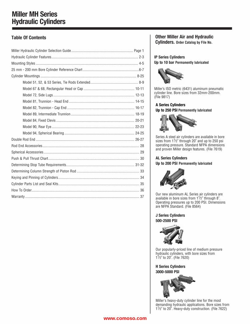
A Series CylindersUp to 250 PSI Permanently lubricated
Series A steel air cylinders are available in boresizes from 11⁄2" through 20" and up to 250 psioperating pressure. Standard NFPA dimensionsand proven Miller design features. (File 7619)
AL Series CylindersUp to 200 PSI Permanently lubricated
Our new aluminum AL Series air cylinders areavailable in bore sizes from 11⁄2" through 8".Operating pressures up to 200 PSI. Dimensionsare NFPA Standard. (File 8564)
J Series Cylinders500-2500 PSI
Our popularly-priced line of medium pressurehydraulic cylinders, with bore sizes from 11⁄2" to 20". (File 7620)
H Series Cylinders3000-5000 PSI
Miller's heavy-duty cylinder line for the mostdemanding hydraulic applications. Bore sizes from11⁄2" to 20". Heavy-duty construction. (File 7622)
Miller MH SeriesHydraulic Cylinders
Table Of Contents
Miller Hydraulic Cylinder Selection Guide ................................................................... Page 1
Hydraulic Cylinder Features.............................................................................................. 2-3
Mounting Styles ............................................................................................................... 4-5
25 mm - 200 mm Bore Cylinder Reference Chart .............................................................6-7
Cylinder Mountings ........................................................................................................ 8-25
Model 51, 52, & 53 Series, Tie Rods Extended.................................................... 8-9
Model 67 & 68, Rectangular Head or Cap ....................................................... 10-11
Model 72, Side Lugs ........................................................................................ 12-13
Model 81, Trunnion - Head End ....................................................................... 14-15
Model 82, Trunnion - Cap End ......................................................................... 16-17
Model 89, Intermediate Trunnion ..................................................................... 18-19
Model 84, Fixed Clevis ..................................................................................... 20-21
Model 90, Rear Eye.......................................................................................... 22-23
Model 94, Spherical Bearing ............................................................................ 24-25
Double Rod End ........................................................................................................... 26-27
Rod End Accessories......................................................................................................... 28
Spherical Accessories........................................................................................................ 29
Push & Pull Thrust Chart................................................................................................... 30
Determining Stop Tube Requirements.......................................................................... 31-32
Determining Column Strength of Piston Rod .................................................................... 33
Keying and Pinning of Cylinders........................................................................................ 34
Cylinder Parts List and Seal Kits........................................................................................ 35
How To Order..................................................................................................................... 36
Warranty ............................................................................................................................ 37
Other Miller Air and HydraulicCylinders. Order Catalog by File No.
IP Series CylindersUp to 10 bar Permanently lubricated
Miller’s ISO metric (6431) aluminum pneumaticcylinder line. Bore sizes from 32mm-200mm. (File 9817)
www.comoso.com
Miller MH SeriesHydraulic Cylinder Selection Guide
Selecting a Miller Hydraulic Cylinder
Miller hydraulic cylinders are selected and sized primarily based on force requirements and available operating pressure. The MH Series is a heavy-duty design
intended for normal industrial service at internal operating pressures up to 210 bar. It is available in mounting styles and bore sizes from 25mm to 200 mm.
Steps in Selecting the Correct Cylinder
Detailed engineering information on bore size selection, oversize rods, stop tubesand the like is located in this catalog. See Table of Contents on previous page.
Step 1 — Determine the correct cylinder bore size required based upon operating pressure and thrust required (See page 30).
Step 2 — Select the mounting style which is required for your application (see pages 4 & 5).
Step 3 — On the appropriate catalog page for the mounting style selected, review bore and rod sizes available.
Step 4 — Choose a rod end style and, if desired, rod end accessories (pages 28 & 29), and optional cushions.
Step 5 — Consider the conditions listed below which may require further modifications to the cylinder you have selected. Application Engineering assistance is readily available by contacting any of the Miller facilities listed on the back cover of this catalog.
Step 6 — Refer to “How to Order” section on (page 36) to develop the part number and place your order.
Rapid Starts or Stops
Long Stroke
High Column Loading-Long Push Stroke
Loads
Use severe service pressure rating only. Confirm thatsufficient thrust is available to accelerate or deceleratecylinder and load within prescribed distances. Ifoptional cushions are selected and will be used toreduce shock during deceleration, check that peakpressures will be within acceptable limits.
Check whether stop tube may be required to preventexcess bearing loads and wear.
Determine if standard size piston rod is strong enoughto accommodate intended load without buckling.
When high side loads and similar severe or unusualoperating conditions are anticipated, please consult aMiller application engineer for recommendationsconcerning optional bushing material and design.
OperatingTemperatures
Sufficient Speed
FluidCompatibility
The standard operating temperature range of the Urethane sealsused in the MH Series is -29˚C to 71˚C. For temperatures inexcess of that range, optional high temperature seals will berequired.
Confirm that standard port size permits sufficient flow toaccommodate speed requirements.
The standard MH seals are compatible with petroleum based fluids.
ApplicationCondition Check the following
ApplicationCondition Check the following
Fluid power cylinders are designed to be linear actuators. They are intended to provide motion and force along the centerline of the rod. Since they have limited capacityto withstand eccentric or radial loads, they should not be employed as linear bearings. Good machine design practice requires that proper alignment be maintained toavoid excessive bearing loads. Any premature failure resulting from side loading is not considered a warranty failure. If your design involves the possibility of side load-ing, please contact the Miller Fluid Power application engineering department.
1
www.comoso.com
Miller MH SeriesHydraulic Cylinders
Standard Design Features toMaximize Performance and Uptime
2
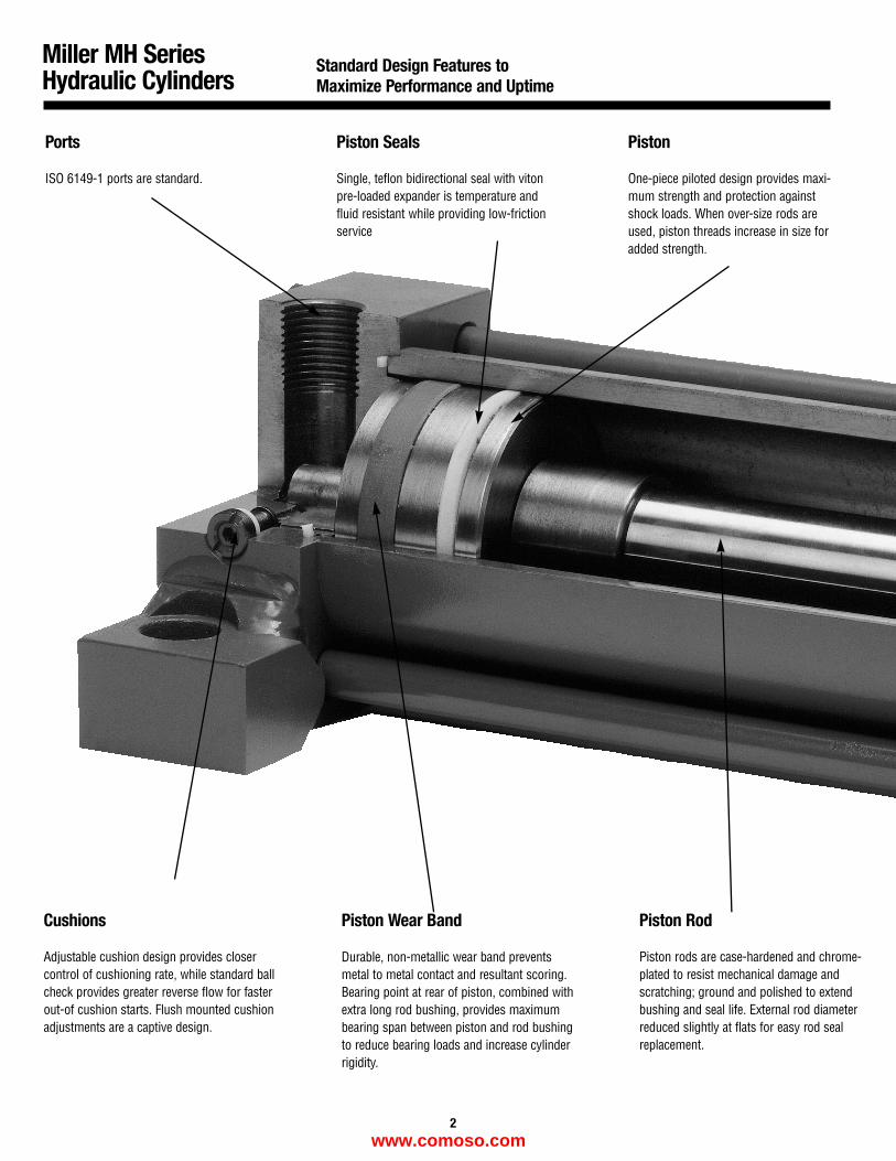
Ports
ISO 6149-1 ports are standard.
Piston Seals
Single, teflon bidirectional seal with vitonpre-loaded expander is temperature andfluid resistant while providing low-frictionservice
Piston
One-piece piloted design provides maxi-mum strength and protection againstshock loads. When over-size rods areused, piston threads increase in size foradded strength.
Cushions
Adjustable cushion design provides closercontrol of cushioning rate, while standard ballcheck provides greater reverse flow for fasterout-of cushion starts. Flush mounted cushionadjustments are a captive design.
Piston Wear Band
Durable, non-metallic wear band preventsmetal to metal contact and resultant scoring.Bearing point at rear of piston, combined withextra long rod bushing, provides maximumbearing span between piston and rod bushingto reduce bearing loads and increase cylinderrigidity.
Piston Rod
Piston rods are case-hardened and chrome-plated to resist mechanical damage andscratching; ground and polished to extendbushing and seal life. External rod diameterreduced slightly at flats for easy rod sealreplacement.
www.comoso.com
Miller MH SeriesHydraulic Cylinders
Standard Design Features toMaximize Performance and Uptime
3
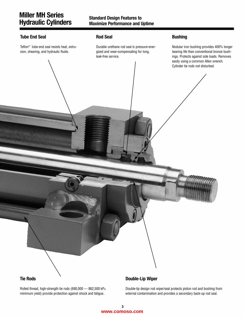
Tube End Seal
Teflon® “ tube-end seal resists heat, extru-sion, shearing, and hydraulic fluids.
Rod Seal
Durable urethane rod seal is pressure-ener-gized and wear-compensating for long,leak-free service.
Bushing
Nodular iron bushing provides 400% longerbearing life than conventional bronze bush-ings. Protects against side loads. Removeseasily using a common Allen wrench.Cylinder tie rods not disturbed.
Tie Rods
Rolled thread, high-strength tie rods (690,000 — 862,500 kPa
minimum yield) provide protection against shock and fatigue.
Double-Lip Wiper
Double-lip design rod wiper/seal protects piston rod and bushing fromexternal contamination and provides a secondary back-up rod seal.
www.comoso.com
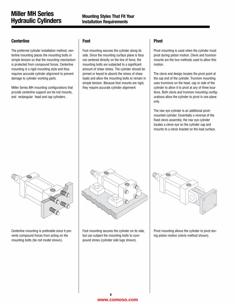
Centerline
The preferred cylinder installation method, cen-terline mounting places the mounting bolts insimple tension so that the mounting mechanismis protected from compound forces. Centerlinemounting is a rigid mounting style and thusrequires accurate cylinder alignment to preventdamage to cylinder working parts.
Miller Series MH mounting configurations thatprovide centerline support are tie-rod mounts,and rectangular head and cap cylinders.
Centerline mounting is preferable since it pre-vents compound forces from acting on themounting bolts (tie rod model shown).
Foot
Foot mounting secures the cylinder along itsside. Since the mounting surface plane is thusnot centered directly on the line of force, themounting bolts are subjected to a significantamount of shear stress. The cylinder should bepinned or keyed to absorb the stress of shearloads and allow the mounting bolts to remain insimple tension. Because foot mounts are rigid,they require accurate cylinder alignment.
Foot mounting secures the cylinder on its side,but can subject the mounting bolts to com-pound stress (cylinder side lugs shown).
Pivot
Pivot mounting is used when the cylinder mustpivot during piston motion. Clevis and trunnionmounts are the two methods used to allow thismotion.
The clevis end design locates the pivot point atthe cap end of the cylinder. Trunnion mountinguses trunnions on the head, cap or side of thecylinder to allow it to pivot at any of three loca-tions. Both clevis and trunnion mounting config-urations allow the cylinder to pivot in one planeonly.
The rear eye cylinder is an additional pivot-mounted cylinder. Essentially a reversal of thefixed clevis assembly, the rear eye cylinderlocates a clevis eye on the cylinder cap andmounts to a clevis bracket on the load surface.
Pivot mounting allows the cylinder to pivot dur-ing piston motion (clevis method shown).
Miller MH SeriesHydraulic Cylinders
Mounting Styles That Fit YourInstallation Requirements
4
www.comoso.com
Miller MH SeriesHydraulic Cylinders
Index12 Mounting Styles Available
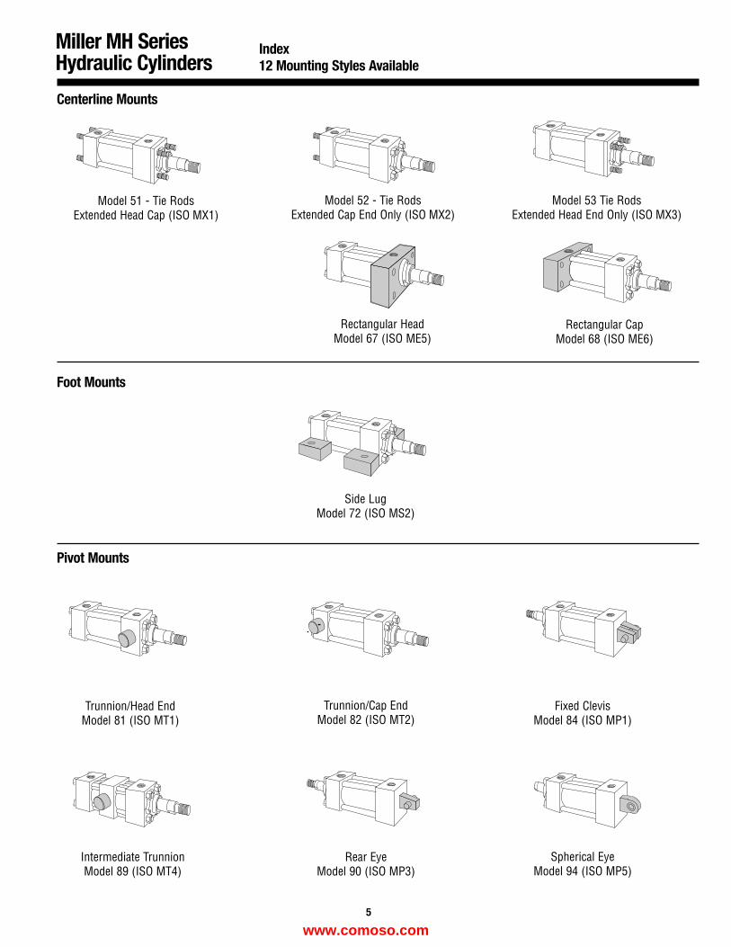
Centerline Mounts
Model 51 - Tie Rods Extended Head Cap (ISO MX1)
Model 52 - Tie RodsExtended Cap End Only (ISO MX2)
Model 53 Tie RodsExtended Head End Only (ISO MX3)
Side LugModel 72 (ISO MS2)
Trunnion/Head EndModel 81 (ISO MT1)
Trunnion/Cap EndModel 82 (ISO MT2)
Fixed ClevisModel 84 (ISO MP1)
Spherical EyeModel 94 (ISO MP5)
Intermediate TrunnionModel 89 (ISO MT4)
Rear EyeModel 90 (ISO MP3)
Foot Mounts
Pivot Mounts
5
Rectangular HeadModel 67 (ISO ME5)
Rectangular CapModel 68 (ISO ME6)
www.comoso.com
Miller MH SeriesHydraulic Cylinders
6
25mm - 200mm Bore Cylinders
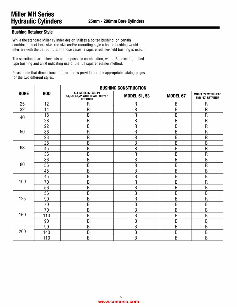
Bushing Retainer Style
25 12 R R B R32 14 R R B R
40 18 B R B R28 R R B R
5022 B R B R36 R R B R28 R R B R
6328 B B B B45 B R B R36 B R B R
8036 B B B B56 B R B R45 B B B B
10045 B B B B70 B R B R56 B B B B
12556 B B B B90 B R B R70 B B B B
16070 B B B B110 B B B B90 B B B B
20090 B B B B140 B B B B110 B B B B
BORE ROD ALL MODELS EXCEPT51, 53, 67,72 WITH HEAD END “K”
RETAINER MODEL 51, 53
BUSHING CONSTRUCTION
MODEL 67 MODEL 72 WITH HEADEND “K” RETAINER
While the standard Miller cylinder design utilizes a bolted bushing, on certaincombinations of bore size. rod size and/or mounting style a bolted bushing wouldinterfere with the tie rod nuts. In those cases, a square retainer-held bushing is used.
The selection chart below lists all the possible combination, with a B indicating boltedtype bushing and an R indicating use of the full square retainer method.
Please note that dimensional information is provided on the appropriate catalog pagesfor the two different styles.
www.comoso.com
BORE
“M” “S” “N” “B” “J” “F” “G”ISO 6149-1 SAE NPT BSPP BSPT SAE
METRICSTRAIGHT STRAIGHT TAPERED PARALLEL TAPERED 4-BOLTSTRAIGHTTHREAD THREAD THREAD THREAD THREAD FLANGE THREAD
PORT PORT PORT PORT PORT PORT(STD) (OPT) (OPT) (OPT) (OPT) (OPT)
(OPT)
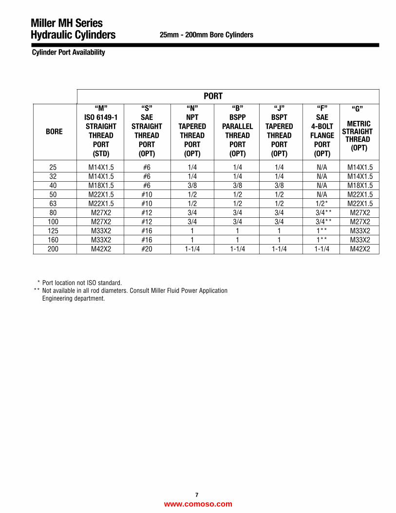
25 M14X1.5 #6 1/4 1/4 1/4 N/A M14X1.532 M14X1.5 #6 1/4 1/4 1/4 N/A M14X1.540 M18X1.5 #6 3/8 3/8 3/8 N/A M18X1.5 50 M22X1.5 #10 1/2 1/2 1/2 N/A M22X1.563 M22X1.5 #10 1/2 1/2 1/2 1/2* M22X1.580 M27X2 #12 3/4 3/4 3/4 3/4** M27X2100 M27X2 #12 3/4 3/4 3/4 3/4** M27X2125 M33X2 #16 1 1 1 1** M33X2160 M33X2 #16 1 1 1 1** M33X2200 M42X2 #20 1-1/4 1-1/4 1-1/4 1-1/4 M42X2
* Port location not ISO standard.** Not available in all rod diameters. Consult Miller Fluid Power Application
Engineering department.
7
Miller MH SeriesHydraulic Cylinders 25mm - 200mm Bore Cylinders
Cylinder Port Availability
PORT
www.comoso.com
STROKE + PJ
GK
JWF
EE PORT SIZEVE
VMA
STROKE + ZJ
KK
MM
BB
DD
B
D
1
2
3
4
WRENCH FLATS
TG
RD
AAE (SQ.)
Y
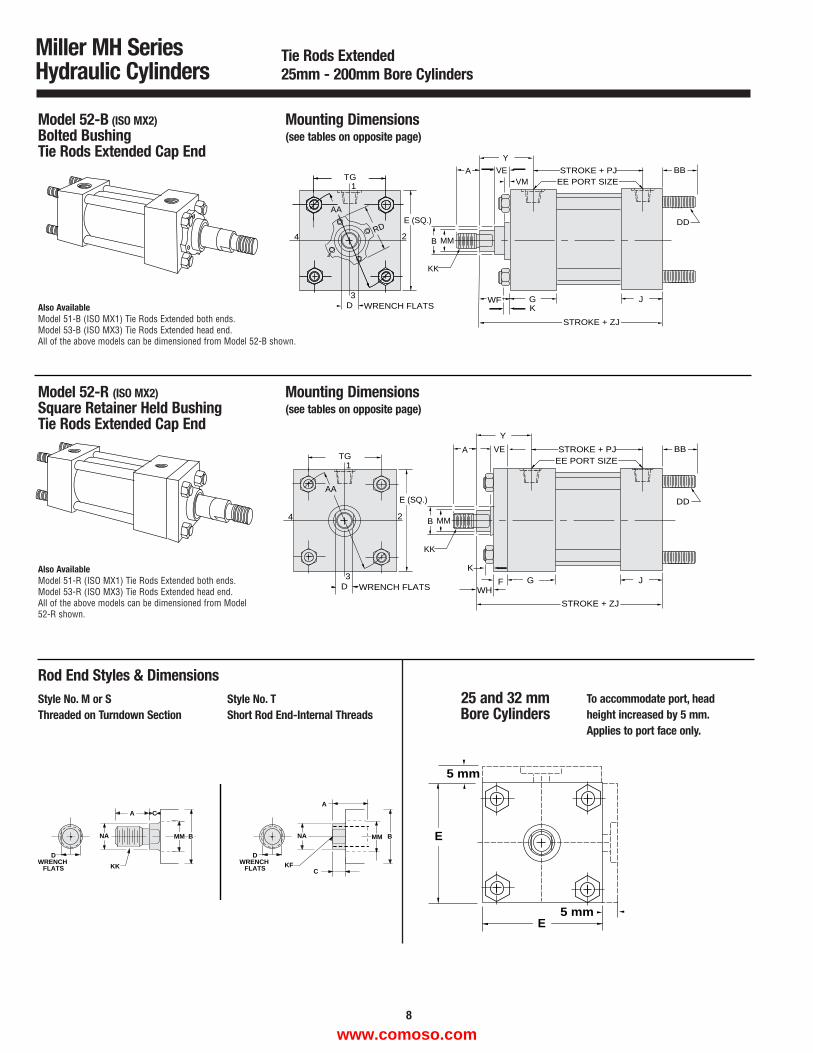
Model 52-B (ISO MX2)Bolted BushingTie Rods Extended Cap End
Mounting Dimensions(see tables on opposite page)
G J
STROKE + ZJ
BB
DD
STROKE + PJEE PORT SIZE
VEA
KK
MMB
F
K
WH
1
D
TG
2
3
4
WRENCH FLATS
AAE (SQ.)
Y
Model 52-R (ISO MX2)Square Retainer Held BushingTie Rods Extended Cap End
Mounting Dimensions(see tables on opposite page)
Miller MH SeriesHydraulic Cylinders
DWRENCH
FLATS
DWRENCH
FLATS
CA
NA
KKC
A
NA
KF
MM B BMM
Rod End Styles & DimensionsStyle No. M or SThreaded on Turndown Section
Style No. TShort Rod End-Internal Threads
Tie Rods Extended25mm - 200mm Bore Cylinders
Also AvailableModel 51-B (ISO MX1) Tie Rods Extended both ends. Model 53-B (ISO MX3) Tie Rods Extended head end.All of the above models can be dimensioned from Model 52-B shown.
Also AvailableModel 51-R (ISO MX1) Tie Rods Extended both ends.Model 53-R (ISO MX3) Tie Rods Extended head end.All of the above models can be dimensioned from Model52-R shown.
25 and 32 mmBore Cylinders
To accommodate port, head height increased by 5 mm.Applies to port face only.
5 mm
5 mm
E
E
8
www.comoso.com
Miller MH SeriesHydraulic Cylinders
Tie Rods Extended25mm - 200mm Bore Cylinders
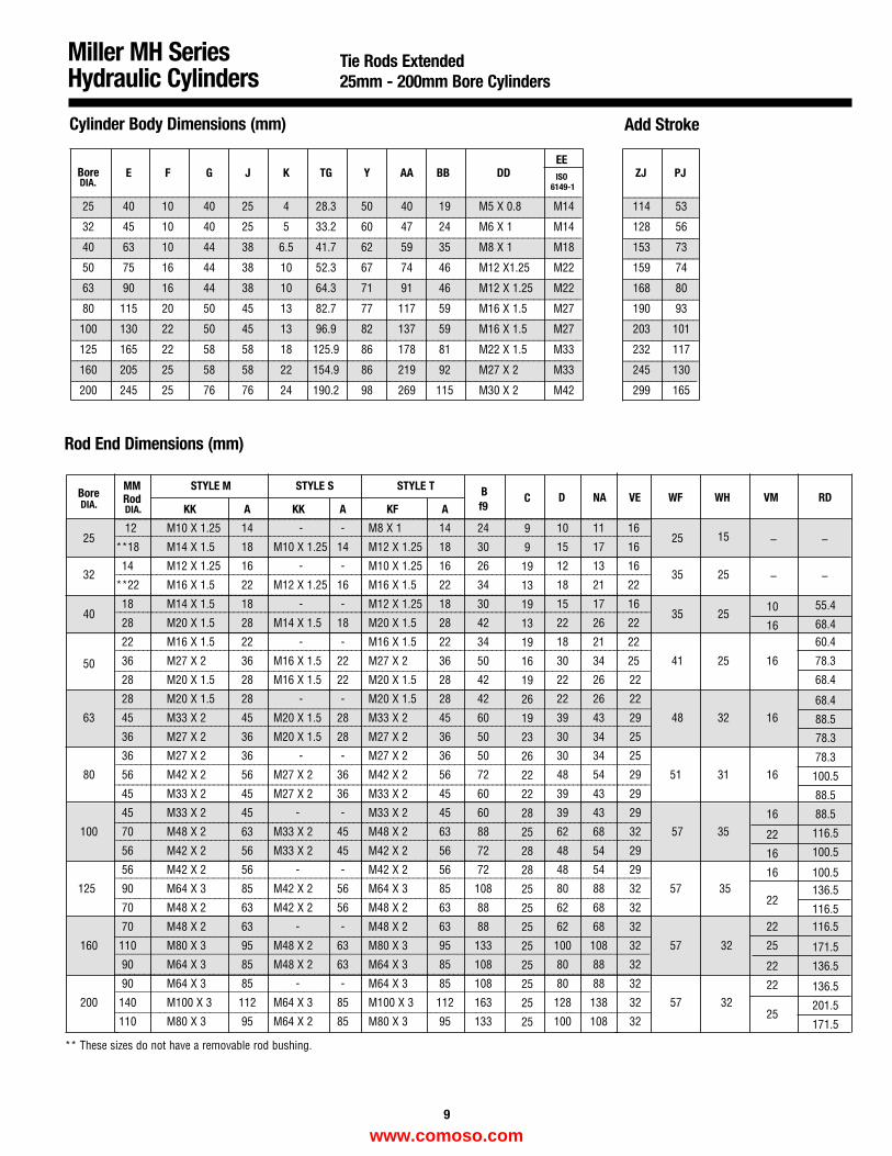
Cylinder Body Dimensions (mm) Add Stroke
Bore E F G J K TG Y AA BB DDEE
ZJ PJISO6149-1
25 40 10 40 25 4 28.3 50 40 19 M5 X 0.8 M14 114 53
32 45 10 40 25 5 33.2 60 47 24 M6 X 1 M14 128 56
40 63 10 44 38 6.5 41.7 62 59 35 M8 X 1 M18 153 73
50 75 16 44 38 10 52.3 67 74 46 M12 X1.25 M22 159 74
63 90 16 44 38 10 64.3 71 91 46 M12 X 1.25 M22 168 80
80 115 20 50 45 13 82.7 77 117 59 M16 X 1.5 M27 190 93
100 130 22 50 45 13 96.9 82 137 59 M16 X 1.5 M27 203 101
125 165 22 58 58 18 125.9 86 178 81 M22 X 1.5 M33 232 117
160 205 25 58 58 22 154.9 86 219 92 M27 X 2 M33 245 130
200 245 25 76 76 24 190.2 98 269 115 M30 X 2 M42 299 165
_____________
_____________
_____________
_____________
_____________
_____________
_____________
_____________
_____________
_____________
________________________________________________________________________________________________
________________________________________________________________________________________________
________________________________________________________________________________________________
________________________________________________________________________________________________
________________________________________________________________________________________________
________________________________________________________________________________________________
________________________________________________________________________________________________
________________________________________________________________________________________________
________________________________________________________________________________________________
________________________________________________________________________________________________
BoreMM STYLE M STYLE S STYLE T B RD
DIA. RodKK A KK A KF A f9
D NA VE WF WH VM
2512 M10 X 1.25 14 - - M8 X 1 14 24 10 11 16
25 15**18 M14 X 1.5 18 M10 X 1.25 14 M12 X 1.25 18 30 15 17 16
3214 M12 X 1.25 16 - - M10 X 1.25 16 26 12 13 16
35 25**22 M16 X 1.5 22 M12 X 1.25 16 M16 X 1.5 22 34 18 21 22
4018 M14 X 1.5 18 - - M12 X 1.25 18 30 15 17 16
35 2555.4
28 M20 X 1.5 28 M14 X 1.5 18 M20 X 1.5 28 42 22 26 22 68.422 M16 X 1.5 22 - - M16 X 1.5 22 34 18 21 22 60.4
50 36 M27 X 2 36 M16 X 1.5 22 M27 X 2 36 50 30 34 25 41 25 16 78.3
28 M20 X 1.5 28 M16 X 1.5 22 M20 X 1.5 28 42 22 26 22 68.4
28 M20 X 1.5 28 - - M20 X 1.5 28 42 22 26 22 68.463 45 M33 X 2 45 M20 X 1.5 28 M33 X 2 45 60 39 43 29 48 32 16
36 M27 X 2 36 M20 X 1.5 28 M27 X 2 36 50 30 34 2588.5
36 M27 X 2 36 - - M27 X 2 36 50 30 34 25 78.380 56 M42 X 2 56 M27 X 2 36 M42 X 2 56 72 48 54 29 51 31 16 100.5
45 M33 X 2 45 M27 X 2 36 M33 X 2 45 60 39 43 29 88.545 M33 X 2 45 - - M33 X 2 45 60 39 43 29 16 88.5
100 70 M48 X 2 63 M33 X 2 45 M48 X 2 63 88 62 68 32 57 35 22 116.556 M42 X 2 56 M33 X 2 45 M42 X 2 56 72 48 54 29 16 100.556 M42 X 2 56 - - M42 X 2 56 72 48 54 29 16 100.5
125 90 M64 X 3 85 M42 X 2 56 M64 X 3 85 108 80 88 32 57 35 136.570 M48 X 2 63 M42 X 2 56 M48 X 2 63 88 62 68 32
22116.5
70 M48 X 2 63 - - M48 X 2 63 88 62 68 32 22 116.5
160 110 M80 X 3 95 M48 X 2 63 M80 X 3 95 133 100 108 32 57 32 25 171.590 M64 X 3 85 M48 X 2 63 M64 X 3 85 108 80 88 32 22 136.590 M64 X 3 85 - - M64 X 3 85 108 80 88 32 22 136.5
200 140 M100 X 3 112 M64 X 3 85 M100 X 3 112 163 128 138 32 57 32 201.5110 M80 X 3 95 M64 X 2 85 M80 X 3 95 133 100 108 32
25171.5
DIA.
Rod End Dimensions (mm)
________________________________________________________________________________________________________
________________________________________________________________________________________________________
_____________________________________________________________________________________________________________________
________________________________________________________________________________________________________
________________________________________________________________________________________________________
____________________________________________________________________________________________________
_______________________________________________________________________________________________________________________
______________________________________________________________________________________________________________________
___________________________________________________________________________________________________________
__________________________________________________________________________________________________________
_____________________________________________________________________________________________________
___________________________________________________________________________________________________________
_______________________________________________________________________________________________
78.3
9
______________________________________________________________________________________________________________________
______________________________________________________________________________________________________________________
______________________________________________________________________________________________________________________
______________________________________________________________________________________________________________________
___________________________________________________________________________________________________
______________________________________________________________________________________________________________________
________________________________________________________________________________________________________
_________________________________________________________________________________________________
______________________________________________________________________________________________________________________
________________________________________________________________________________________________________
________________________________________________________________________________________________
______________________________________________________________________________________________
______________________________________________________________________________________________
DIA.
C
9
9
19
13
19
13
19
16
19
26
19
23
26
22
22
28
25
28
28
25
25
25
25
25
25
25
25
10
16
–
–
–
–
** These sizes do not have a removable rod bushing.
www.comoso.com
STROKE + PJEE PORT SIZE
A
G JWF K
STROKE + ZB
KK
MMB
D
1
2
3
4
WRENCH FLATS
RDE
TDUO
R
FB
Y
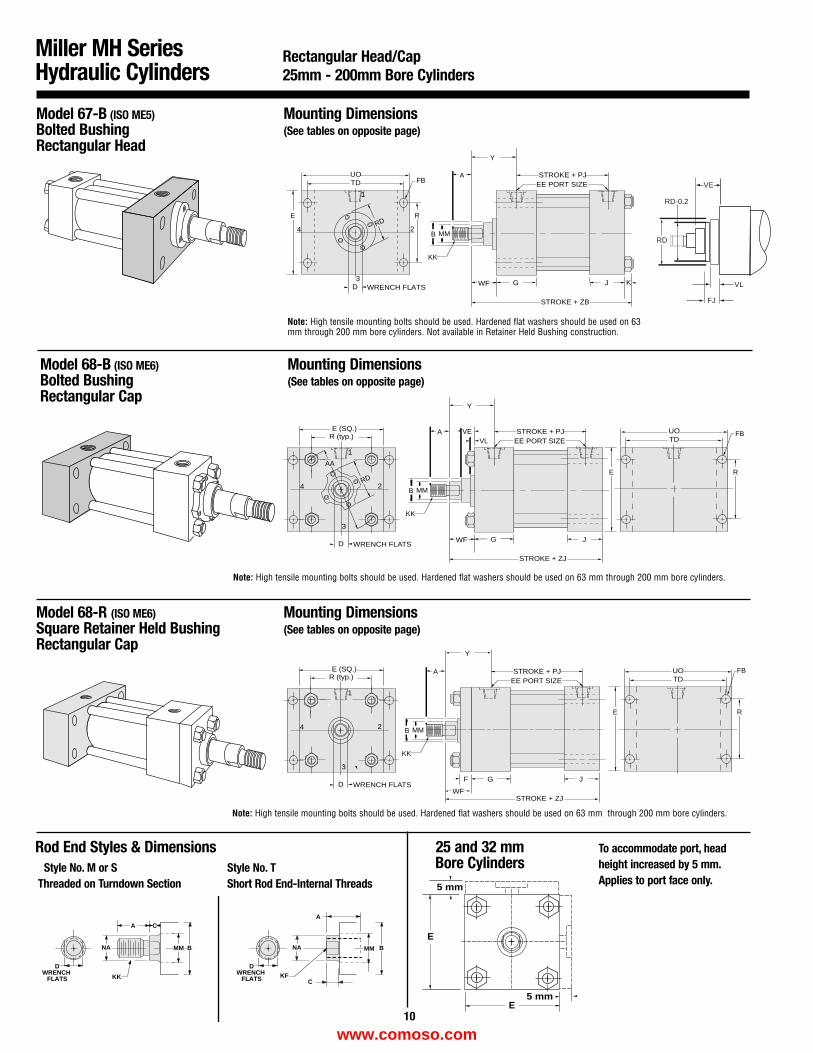
Model 67-B (ISO ME5)Bolted BushingRectangular Head
Mounting Dimensions(See tables on opposite page)
J
STROKE + PJ
GF
EE PORT SIZE
Y
A
KK
MMB
STROKE + ZJWF
E
TDUO
R
FB
D
1
2
3
4
WRENCH FLATS
R (typ.)E (SQ.)
Model 68-R (ISO ME6)Square Retainer Held BushingRectangular Cap
Mounting Dimensions(See tables on opposite page)
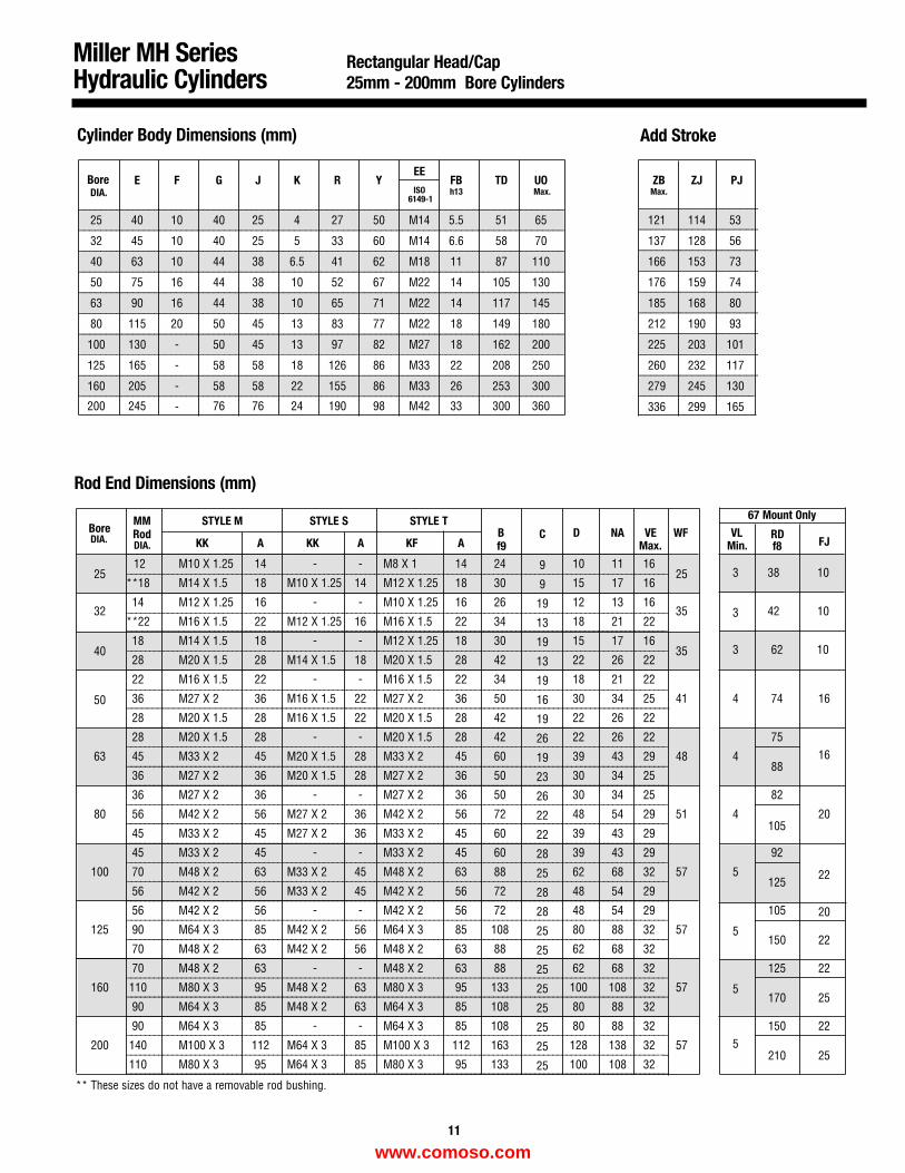
Miller MH SeriesHydraulic Cylinders
Rectangular Head/Cap25mm - 200mm Bore Cylinders
STROKE + PJ
G JWF
EE PORT SIZEVE
VLA
STROKE + ZJ
KK
MMB
E
TDUO
R
FB
RD
D
1
2
3
4
WRENCH FLATS
AA
R (typ.)E (SQ.)
Y
Model 68-B (ISO ME6)Bolted BushingRectangular Cap
Mounting Dimensions(See tables on opposite page)
Note: High tensile mounting bolts should be used. Hardened flat washers should be used on 63mm through 200 mm bore cylinders. Not available in Retainer Held Bushing construction.
Note: High tensile mounting bolts should be used. Hardened flat washers should be used on 63 mm through 200 mm bore cylinders.
Note: High tensile mounting bolts should be used. Hardened flat washers should be used on 63 mm through 200 mm bore cylinders.
DWRENCH
FLATS
DWRENCH
FLATS
CA
NA
KKC
A
NA
KF
MM B BMM
Rod End Styles & Dimensions
5 mm
5 mm
E
E
Style No. M or SThreaded on Turndown Section
Style No. TShort Rod End-Internal Threads
25 and 32 mmBore Cylinders
To accommodate port, head height increased by 5 mm.Applies to port face only.
10
VE
RD
RD-0.2
FJ
VL
www.comoso.com
Miller MH SeriesHydraulic Cylinders
Rectangular Head/Cap 25mm - 200mm Bore Cylinders
Cylinder Body Dimensions (mm) Add Stroke
Bore E F G J K R YEE
FB TD UO ZB ZJ PJISO Max. Max.
6149-1h13
25 40 10 40 25 4 27 50 M14 5.5 51 65 121 114 53
32 45 10 40 25 5 33 60 M14 6.6 58 70 137 128 56
40 63 10 44 38 6.5 41 62 M18 11 87 110 166 153 73
50 75 16 44 38 10 52 67 M22 14 105 130 176 159 74
63 90 16 44 38 10 65 71 M22 14 117 145 185 168 80
80 115 20 50 45 13 83 77 M22 18 149 180 212 190 93
100 130 - 50 45 13 97 82 M27 18 162 200 225 203 101
125 165 - 58 58 18 126 86 M33 22 208 250 260 232 117
160 205 - 58 58 22 155 86 M33 26 253 300 279 245 130
200 245 - 76 76 24 190 98 M42 33 300 360 336 299 165
____________________
____________________
____________________
____________________
____________________
____________________
____________________
____________________
____________________
____________________
__________________________________________________________________________________________
__________________________________________________________________________________________
__________________________________________________________________________________________
__________________________________________________________________________________________
__________________________________________________________________________________________
__________________________________________________________________________________________
__________________________________________________________________________________________
__________________________________________________________________________________________
__________________________________________________________________________________________
__________________________________________________________________________________________
BoreMM STYLE M STYLE S STYLE T
B RDFJ
RodKK A KK A KF A f9
D NA VE WF VLf8
2512 M10 X 1.25 14 - - M8 X 1 14 24 10 11 16
25 3 38 10**18 M14 X 1.5 18 M10 X 1.25 14 M12 X 1.25 18 30 15 17 16
3214 M12 X 1.25 16 - - M10 X 1.25 16 26 12 13 16
35 3 42 10**22 M16 X 1.5 22 M12 X 1.25 16 M16 X 1.5 22 34 18 21 22
4018 M14 X 1.5 18 - - M12 X 1.25 18 30 15 17 16
35 3 62 1028 M20 X 1.5 28 M14 X 1.5 18 M20 X 1.5 28 42 22 26 22
22 M16 X 1.5 22 - - M16 X 1.5 22 34 18 21 22
450 36 M27 X 2 36 M16 X 1.5 22 M27 X 2 36 50 30 34 25 41 74 16
28 M20 X 1.5 28 M16 X 1.5 22 M20 X 1.5 28 42 22 26 22
28 M20 X 1.5 28 - - M20 X 1.5 28 42 22 26 22 751663 45 M33 X 2 45 M20 X 1.5 28 M33 X 2 45 60 39 43 29 48 4
8836 M27 X 2 36 M20 X 1.5 28 M27 X 2 36 50 30 34 25
36 M27 X 2 36 - - M27 X 2 36 50 30 34 25 82
80 56 M42 X 2 56 M27 X 2 36 M42 X 2 56 72 48 54 29 51 4 20
45 M33 X 2 45 M27 X 2 36 M33 X 2 45 60 39 43 29105
45 M33 X 2 45 - - M33 X 2 45 60 39 43 29 92
100 70 M48 X 2 63 M33 X 2 45 M48 X 2 63 88 62 68 32 57 5 2256 M42 X 2 56 M33 X 2 45 M42 X 2 56 72 48 54 29
125
56 M42 X 2 56 - - M42 X 2 56 72 48 54 29 105 20125 90 M64 X 3 85 M42 X 2 56 M64 X 3 85 108 80 88 32 57
2270 M48 X 2 63 M42 X 2 56 M48 X 2 63 88 62 68 32
5150
70 M48 X 2 63 - - M48 X 2 63 88 62 68 32 125 22
160 110 M80 X 3 95 M48 X 2 63 M80 X 3 95 133 100 108 32 57
90 M64 X 3 85 M48 X 2 63 M64 X 3 85 108 80 88 325
170 25
90 M64 X 3 85 - - M64 X 3 85 108 80 88 32 150 22
200 140 M100 X 3 112 M64 X 3 85 M100 X 3 112 163 128 138 32 57
110 M80 X 3 95 M64 X 3 85 M80 X 3 95 133 100 108 32
5210 25
_______________________________________________________________________________________________________
_______________________________________________________________________________________________________
____________________________________________________________________________________________________________________
________________________________________________________________________________________________________
__________________________________________________________________________________________________________________
______________________________________________________________________________________________________________________
______________________________________________________________________________________________________________________
______________________________________________________________________________________________________________________
______________________________________________________________________________________________________________________
______________________________________________________________________________________________________________________
______________________________________________________________________________________________________________________
______________________________________________________________________________________________________________________
______________________________________________________________________________________________________________________
______________________________________________________________________________________________________________________
DIA.
Rod End Dimensions (mm)
______________________________________________________________________________________________________________________
______________________________________________________________________________________________________________________
______________________________________________________________________________________________________________________
______________________________________________________________________________________________________________________
______________________________________________________________________________________________________________________
______________________________________________________________________________________________________________________
______________________________________________________________________________________________________________________
______________________________________________________________________________________________________________________
______________________________________________________________________________________________________________________
______________________________________________________________________________________________________________________
______________________________________________________________________________________________________________________
______________________________________________________________________________________________________________________
______________________________________________________________________________________________________________________
______________________________________________________________________________________________________________________
67 Mount Only
11
DIA.
DIA.
C
9
9
19
13
19
13
19
16
19
26
19
23
26
22
22
28
25
28
28
25
25
25
25
25
25
25
25
Max. Min.
** These sizes do not have a removable rod bushing.
www.comoso.com

SW K
STROKE + ZB
SWSTROKE + SS
SUWFXS
STROKE + PJSTROKE + ZJ
EE PORT SIZE
Y
VE
A
KK
MMBG JSB
D
RD
WRENCH FLATS
E (SQ.)
TSUS
LH
ST
Model 72-B (ISO MS2)Bolted BushingSide Lug
Mounting Dimensions(See tables on opposite page)
STROKE + PJEE PORT SIZE
WFY
A
STROKE + ZJ
SW K
STROKE + ZB
SUSWSTROKE + SS
SU
G J
XS
KK
MMB
VE
SB
D WRENCH FLATS
E (SQ.)
TSUS
LH
ST
F
Model 72-R (ISO MS2)Square Retainer Held Bushing Side Lug
Mounting Dimensions(See tables on opposite page)
Miller MH SeriesHydraulic Cylinders
Rod End Styles & Dimensions
Side Lug 25mm - 200mm Bore Cylinders
Note: Lugs should be blocked, or a "K" retainer should be mounted on the appropriate end to absorb hydraulic or mechanicalshock. Bolts should not carry shear load.
Note: Lugs should be blocked, or a "K" retainer should be mounted on the appropriate end to absorb hydraulic or mechanicalshock. Bolts should not carry shear load.
DWRENCH
FLATS
DWRENCH
FLATS
CA
NA
KKC
A
NA
KF
MM B BMM
5 mm
5 mm
E
E
Style No. M or SThreaded on Turndown Section
Style No.TShort Rod End-Internal Threads
25 and 32 mmBore Cylinders
To accommodate port, head height increased by 5 mm.Applies to port face only.
12
www.comoso.com
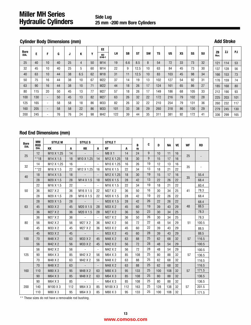
Miller MH SeriesHydraulic Cylinders
Side Lug 25 mm -200 mm Bore Cylinders
Cylinder Body Dimensions (mm)
Rod End Dimensions (mm)
Add Stroke
_____________________________________________________________________________________________________
_____________________________________________________________________________________________________
_________________________________________________________________________________________________________________
_______________________________________________________________________________________________
_____________________________________________________________________________________________________
_____________________________________________________________________________________________________
________________________________________________________________________________________________________
____________________________________________________________________________________________________________________
____________________________________________________________________________________________________________________
______________________________________________________________________________________________________
___________________________________________________________________________________________________________________
______________________________________________________________________________________________________
___________________________________________________________________________________________________________________
______________________________________________________________________________________________________
____________________________________________________________________________________________________________________
____________________________________________________________________________________________________________________
____________________________________________________________________________________________________________________
____________________________________________________________________________________________________________________
____________________________________________________________________________________________________________________
____________________________________________________________________________________________________________________
____________________________________________________________________________________________________________________
____________________________________________________________________________________________________________________
____________________________________________________________________________________________________________________
____________________________________________________________________________________________________________________
____________________________________________________________________________________________________________________
____________________________________________________________________________________________________________________
____________________________________________________________________________________________________________________
____________________________________________________________________________________________________________________
MM STYLE M STYLE S STYLE TB RDBore ROD
KK A KK A KF A f9D NA VE WF
-2512 M10 X 1.25 14 - - M8 X 1 14 24 10 11 16
25**18 M14 X 1.5 18 M10 X 1.25 14 M12 X 1.25 18 30 15 17 16
-3214 M12 X 1.25 16 - - M10 X 1.25 16 26 12 13 16
35**22 M16 X 1.5 22 M12 X 1.25 16 M16 X 1.5 22 34 18 21 22
4018 M14 X 1.5 18 - - M12 X 1.25 18 30 15 17 16
3555.4
28 M20 X 1.5 28 M14 X 1.5 18 M20 X 1.5 28 42 22 26 22 68.4
22 M16 X 1.5 22 - - M16 X 1.5 22 34 18 21 22 60.4
50 36 M27 X 2 36 M16 X 1.5 22 M27 X 2 36 50 30 34 25 41 78.3
28 M20 X 1.5 28 M16 X 1.5 22 M20 X 1.5 28 42 22 26 22 68.4
28 M20 X 1.5 28 - - M20 X 1.5 28 42 22 26 22 68.463 45 M33 X 2 45 M20 X 1.5 28 M33 X 2 45 60 39 43 29 48 88.5
36 M27 X 2 36 M20 X 1.5 28 M27 X 2 36 50 30 34 25 78.3
36 M27 X 2 36 - - M27 X 2 36 50 30 34 25 78.3
80 56 M42 X 2 56 M27 X 2 36 M42 X 2 56 72 48 54 29 51 100.5
45 M33 X 2 45 M27 X 2 36 M33 X 2 45 60 39 43 29 88.545 M33 X 2 45 - - M33 X 2 45 60 39 43 29 88.5
100 70 M48 X 2 63 M33 X 2 45 M48 X 2 63 88 62 68 32 57 116.5
56 M42 X 2 56 M33 X 2 45 M42 X 2 56 72 48 54 29 100.5
56 M42 X 2 56 - - M42 X 2 56 72 48 54 29 100.5125 90 M64 X 3 85 M42 X 2 56 M64 X 3 85 108 80 88 32 57 136.5
70 M48 X 2 63 M42 X 2 56 M48 X 2 63 88 62 68 32 116.570 M48 X 2 63 - - M48 X 2 63 88 62 68 32 116.5
160 110 M80 X 3 95 M48 X 2 63 M80 X 3 95 133 100 108 32 57 171.5
90 M64 X 3 85 M48 X 2 63 M64 X 3 85 108 80 88 32 136.5
90 M64 X 3 85 - - M64 X 3 85 108 80 88 32 136.5
200 140 M100 X 3 112 M64 X 3 85 M100 X 3 112 163 128 138 32 57 201.5
110 M80 X 3 95 M64 X 3 85 M80 X 3 95 133 100 108 32 171.5
_________________
_________________
_________________
_________________
_________________
_________________
_________________
_________________
_________________
_________________
_
______________________________________________________________________________________________________________________________
______________________________________________________________________________________________________________________________
______________________________________________________________________________________________________________________________
______________________________________________________________________________________________________________________________
______________________________________________________________________________________________________________________________
______________________________________________________________________________________________________________________________
______________________________________________________________________________________________________________________________
______________________________________________________________________________________________________________________________
______________________________________________________________________________________________________________________________
______________________________________________________________________________________________________________________________
BoreE F G J K Y
EELH SB ST SW TS US XS SS SUISO
6149-1
25 40 10 40 25 4 50 M14 19 6.6 8.5 8 54 72 33 73 32
32 45 10 40 25 5 60 M14 22 9 12.5 10 63 84 45 73 30
40 63 10 44 38 6.5 62 M18 31 11 12.5 10 83 103 45 98 34
50 75 16 44 38 10 67 M22 37 14 19 13 102 127 54 92 31
63 90 16 44 38 10 71 M22 44 18 26 17 124 161 65 86 27
80 115 20 50 45 13 77 M27 57 18 26 17 149 186 68 105 33
100 130 - 50 45 13 82 M27 63 26 32 22 172 216 79 102 28
125 165 - 58 58 18 86 M33 82 26 32 22 210 254 79 131 36
160 205 - 58 58 22 86 M33 101 33 38 29 260 318 86 130 29
200 245 - 76 76 24 98 M42 122 39 44 35 311 381 92 172 41
ZB ZJ PJMax.
121 114 53
137 128 56
166 153 73
176 159 74
185 168 80
212 190 93
225 203 101
260 232 117
279 245 130
336 299 165
13
DIA.
DIA.DIA.C
9
9
19
13
19
13
19
16
19
26
19
23
26
22
22
28
25
28
28
25
25
25
25
25
25
25
25
** These sizes do not have a removable rod bushing.
www.comoso.com
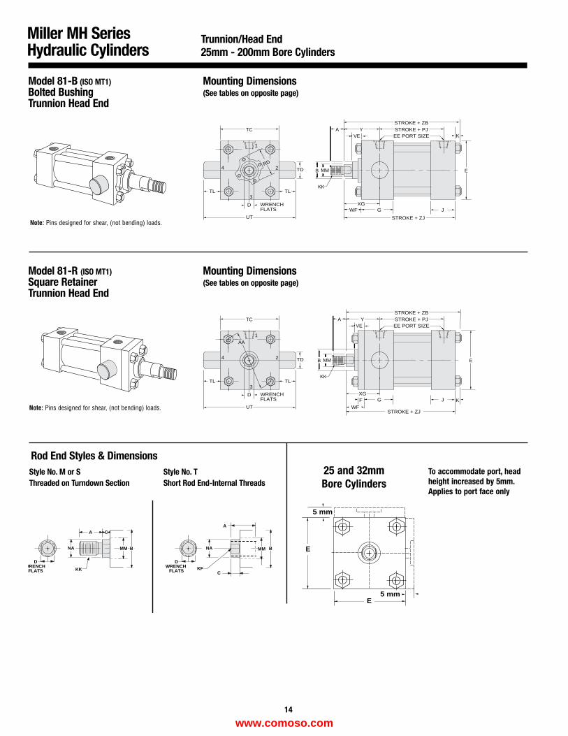
Model 81-B (ISO MT1)Bolted BushingTrunnion Head End
Mounting Dimensions(See tables on opposite page)
Model 81-R (ISO MT1)Square RetainerTrunnion Head End
Mounting Dimensions(See tables on opposite page)
Miller MH SeriesHydraulic Cylinders
DWRENCH
FLATS
DWRENCH
FLATS
CA
NA
KKC
A
NA
KF
MM B BMM
Rod End Styles & Dimensions Style No. M or SThreaded on Turndown Section
Style No. TShort Rod End-Internal Threads
Trunnion/Head End 25mm - 200mm Bore Cylinders
Note: Pins designed for shear, (not bending) loads.
Note: Pins designed for shear, (not bending) loads.STROKE + ZJ
STROKE + PJ
G J
STROKE + ZB
EE PORT SIZEVEA Y
K
KK
MMB E
WF
XGD WRENCHFLATS
TC
TD
UT
TLTL
AA1
2
3
4
F
D WRENCHFLATS
TC
TD
UT
TLTL
1
2
3
4
STROKE + ZJ
STROKE + PJ
G J
STROKE + ZB
EE PORT SIZEVEA Y
K
KK
MMB E
WFXG
RD
25 and 32mmBore Cylinders
To accommodate port, headheight increased by 5mm.Applies to port face only
5 mm
5 mm
E
E
14
www.comoso.com
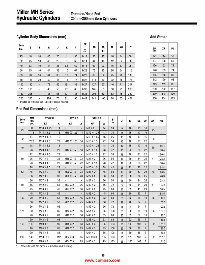
Miller MH SeriesHydraulic Cylinders
Trunnion/Head End25mm-200mm Bore Cylinders
Cylinder Body Dimensions (mm) Add Stroke
____________________
____________________
____________________
____________________
____________________
____________________
____________________
____________________
____________________
____________________
__________________________________________________________________________________________________________________
_______________________________________________________________________________________________________
_______________________________________________________________________________________________________
_______________________________________________________________________________________________________
_______________________________________________________________________________________________________
_______________________________________________________________________________________________________
_______________________________________________________________________________________________________
_______________________________________________________________________________________________________
_______________________________________________________________________________________________________
_______________________________________________________________________________________________________
BoreE F G J K Y
EETC TD TL XG UT
ISO f86149-1
25 40 10 40 25 4 50 M14 38 12 10 44 58
32 45 10 40 25 5 60 M14 44 16 12 54 68
40 63 10 44 38 6.5 62 M18 63 20 16 57 95
50 75 16 44 38 10 67 M22 76 25 20 64 116
63 90 16 44 38 10 71 M22 89 32 25 70 139
80 115 20 50 45 13 77 M27 114 40 32 76 178
100 130 - 72 45 13* 82 M27 127 50 40 71 207
125 165 - 80 58 18* 86 M33 165 63 50 75 265
160 205 - 86 58 22* 86 M33 203 80 63 75 329
200 245 - 106 76 24* 98 M42 241 100 80 85 401
ZB ZJ PJMax.
121 114 53
137 128 56
166 153 73
176 159 74
185 168 80
212 190 93
225 203 101
260 232 117
279 248 130
336 304 165
___________________________________________________________________________________________________
___________________________________________________________________________________________________
____________________________________________________________________________________________________________
_____________________________________________________________________________________________________
___________________________________________________________________________________________________
___________________________________________________________________________________________________
____________________________________________________________________________________________________
______________________________________________________________________________________________________________
______________________________________________________________________________________________________________
______________________________________________________________________________________________________________
______________________________________________________________________________________________________________
______________________________________________________________________________________________________________
______________________________________________________________________________________________________________
______________________________________________________________________________________________________________
___________________________________________________________________________________________________________________
___________________________________________________________________________________________________________________
__________________________________________________________________________________________________________
___________________________________________________________________________________________________________________
___________________________________________________________________________________________________________________
__________________________________________________________________________________________________________
___________________________________________________________________________________________________________________
_______________________________________________________________________________________________________________
_____________
_____________
_____________
_____________
_____________
____________
_____________
_____________
_____________
MM STYLE M STYLE S STYLE TBore RODKK A KK A KF A
BD NA VE WF RD
2512 M10 X 1.25 14 - - M8 X 1 14 24 10 11 16
25**18 M14 X 1.5 18 M10 X 1.25 14 M12 X 1.25 18 30 15 17 16
3214 M12 X 1.25 16 - - M10 X 1.25 16 26 12 13 16
35**22 M16 X 1.5 22 M12 X 1.25 16 M16 X 1.5 22 34 18 21 22
4018 M14 X 1.5 18 - - M12 X 1.25 18 30 15 17 16
3528 M20 X 1.5 28 M14 X 1.5 18 M20 X 1.5 28 42 22 26 22
22 M16 X 1.5 22 - - M16 X 1.5 22 34 18 21 22
50 36 M27 X 2 36 M16 X 1.5 22 M27 X 2 36 50 30 34 25 41
28 M20 X 1.5 28 M16 X 1.5 22 M20 X 1.5 28 42 22 26 22
28 M20 X 1.5 28 - - M20 X 1.5 28 42 22 26 22
63 45 M33 X 2 45 M20 X 1.5 28 M33 X 2 45 60 39 43 29 48
36 M27 X 2 36 M20 X 1.5 28 M27 X 2 36 50 30 34 25
36 M27 X 2 36 - - M27 X 2 36 50 30 34 25
80 56 M42 X 2 56 M27 X 2 36 M42 X 2 56 72 48 54 29 51
45 M33 X 2 45 M27 X 2 36 M33 X 2 45 60 39 43 29
45 M33 X 2 45 - - M33 X 2 45 60 39 43 7
100 70 M48 X 2 63 M33 X 2 45 M48 X 2 63 88 62 68 10 35
56 M42 X 2 56 M33 X 2 45 M42 X 2 56 72 48 54 7
56 M42 X 2 56 - - M42 X 2 56 72 48 54 7
125 90 M64 X 3 85 M42 X 2 56 M64 X 3 85 108 80 88 10 35
70 M48 X 2 63 M42 X 2 56 M48 X 2 63 88 62 68 10
70 M48 X 2 63 - - M48 X 2 63 88 62 68 7
160 110 M80 X 3 95 M48 X 2 63 M80 X 3 95 133 100 108 7 32
90 M64 X 3 85 M48 X 2 63 M64 X 3 85 108 80 88 7
90 M64 X 3 85 - - M64 X 3 85 108 80 88 7
200 140 M100 X 3 112 M64 X 3 85 M100 X 3 112 163 128 138 7 32
110 M80 X 3 95 M64 X 3 85 M80 X 3 95 133 100 108 7
f9
15
-
-
55.4
68.4
60.4
78.3
68.4
68.4
88.5
78.3
78.3
100.5
88.5
88.5
116.5
100.5
100.5
136.5
116.5
116.5
171.5
136.5
136.5
201.5
171.5
Rod End Dimensions (mm)
DIA.
DIA. DIA.C
9
9
19
13
19
13
19
16
19
26
19
23
26
22
22
28
25
28
28
25
25
25
25
25
25
25
25
* Threaded tie rod holes at head end or square retainer.
** These sizes do not have a removable rod bushing.
www.comoso.com
STROKE + PJ
G J
STROKE + ZB
EE PORT SIZE
STROKE + ZJ
STROKE + XJ
Y
VEA
WF
KK
MMB
D WRENCHFLATS
RDTD
UT
TLTL
1
2
3
4
TCK
E
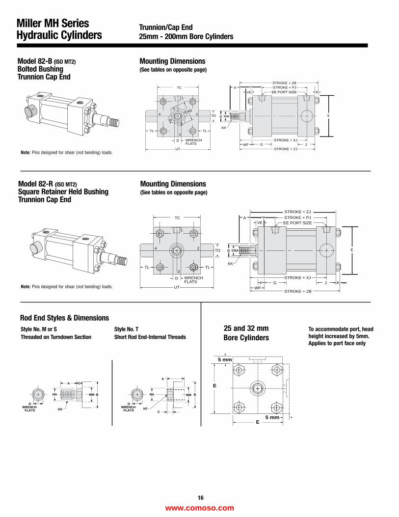
Model 82-B (ISO MT2)Bolted BushingTrunnion Cap End
Mounting Dimensions(See tables on opposite page)
STROKE + ZJ
F K
YVE
A
KK
MMB
STROKE + ZB
G JSTROKE + XJD WRENCH
FLATS
TD
UT
TL TL
1
2
3
4
TC
E
WFJ
STROKE + PJEE PORT SIZE
Model 82-R (ISO MT2)Square Retainer Held BushingTrunnion Cap End
Mounting Dimensions(See tables on opposite page)
Miller MH SeriesHydraulic Cylinders
Trunnion/Cap End 25mm - 200mm Bore Cylinders
Note: Pins designed for shear (not bending) loads.
Note: Pins designed for shear (not bending) loads.
DWRENCH
FLATS
DWRENCH
FLATS
CA
NA
KKC
A
NA
KF
MM B BMM
Rod End Styles & Dimensions Style No. M or SThreaded on Turndown Section
Style No. TShort Rod End-Internal Threads
To accommodate port, headheight increased by 5mm.Applies to port face only
25 and 32 mmBore Cylinders
5 mm
5 mm
E
E
16
www.comoso.com
Miller MH SeriesHydraulic Cylinders
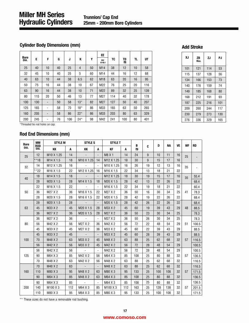
Trunnion/ Cap End25mm - 200mm Bore Cylinders
Cylinder Body Dimensions (mm) Add Stroke
___________________________
___________________________
___________________________
___________________________
___________________________
___________________________
___________________________
___________________________
___________________________
___________________________
XJ ZB ZJ PJMax.
101 121 114 53
115 137 128 56
134 166 153 73
140 176 159 74
149 185 168 80
168 212 191 93
187 225 216 101
209 260 244 117
230 279 273 130
276 336 329 165
Bore E F G J K YEE
TC TD TL UTISO6149.1
25 40 10 40 25 4 50 M14 38 12 10 58
32 45 10 40 25 5 60 M14 44 16 12 68
40 63 10 44 38 6.5 62 M18 63 20 16 95
50 75 16 44 38 10 67 M22 76 25 20 116
63 90 16 44 38 10 71 M22 89 32 25 139
80 115 20 50 46 13 77 M27 114 40 32 178
100 130 - 50 58 13* 82 M27 127 50 40 207
125 165 - 58 70 18* 86 M33 165 63 50 265
160 205 - 58 86 22* 86 M33 203 80 63 329
200 245 - 76 106 24* 98 M42 241 100 80 401
Rod End Dimensions (mm)
______________________________________________________________________________________________
______________________________________________________________________________________________
______________________________________________________________________________________________________
__________________________________________________________________________________________________
_______________________________________________________________________________________________
______________________________________________________________________________________________
______________________________________________________________________________________________
_______________________________________________________________________________________________________
__________________________________________________________________________________________________________
__________________________________________________________________________________________________________
__________________________________________________________________________________________________________
__________________________________________________________________________________________________________
__________________________________________________________________________________________________________
__________________________________________________________________________________________________________
______________________________________________________________________________________________________________
______________________________________________________________________________________________________________
______________________________________________________________________________________________________________
______________________________________________________________________________________________________________
______________________________________________________________________________________________________________
______________________________________________________________________________________________________________
______________________________________________________________________________________________________________
______________________________________________________________________________________________________________
______________________________________________________________________________________________________________
______________________________________________________________________________________________________________
______________________________________________________________________________________________________________
______________________________________________________________________________________________________________
______________________________________________________________________________________________________________
__________________________________________________________________________________________________________
_____________
_____________
_____________
_____________
_____________
____________
_____________
_____________
_____________
MM STYLE M STYLE S STYLE TBore RODKK A KK A KF A
B D NA VE WF RD
25 12 M10 X 1.25 14 - - M8 X 1 14 24 10 11 16 25**18 M14 X 1.5 18 M10 X 1.25 14 M12 X 1.25 18 30 15 17 16
32 14 M12 X 1.25 16 - - M10 X 1.25 16 26 12 13 16 35**22 M16 X 1.5 22 M12 X 1.25 16 M16 X 1.5 22 34 18 21 22
4018 M14 X 1.5 18 - - M12 X 1.25 18 30 15 17 16 3528 M20 X 1.5 28 M14 X 1.5 18 M20 X 1.5 28 42 22 26 22
22 M16 X 1.5 22 - - M16 X 1.5 22 34 18 21 22
50 36 M27 X 2 36 M16 X 1.5 22 M27 X 2 36 50 30 34 25 41
28 M20 X 1.5 28 M16 X 1.5 22 M20 X 1.5 28 42 22 26 22
28 M20 X 1.5 28 - - M20 X 1.5 28 42 22 26 22
63 45 M33 X 2 45 M20 X 1.5 28 M33 X 2 45 60 39 43 29 48
36 M27 X 2 36 M20 X 1.5 28 M27 X 2 36 50 30 34 25
36 M27 X 2 36 - - M27 X 2 36 50 30 34 25
80 56 M42 X 2 56 M27 X 2 36 M42 X 2 56 72 48 54 29 51
45 M33 X 2 45 M27 X 2 36 M33 X 2 45 60 39 43 29
45 M33 X 2 45 - - M33 X 2 45 60 39 43 29
100 70 M48 X 2 63 M33 X 2 45 M48 X 2 63 88 62 68 32 57
56 M42 X 2 56 M33 X 2 45 M42 X 2 56 72 48 54 29
56 M42 X 2 56 - - M42 X 2 56 72 48 54 29
125 90 M64 X 3 85 M42 X 2 56 M64 X 3 85 108 80 88 32 57
70 M48 X 2 63 M42 X 2 56 M48 X 2 63 88 62 68 32
70 M48 X 2 63 - - M48 X 2 63 88 62 68 32
160 110 M80 X 3 95 M48 X 2 63 M80 X 3 95 133 100 108 32 57
90 M64 X 3 85 M48 X 2 63 M64 X 3 85 108 80 88 32
90 M64 X 3 85 - - M64 X 3 85 108 80 88 32200 140 M100 X 3 112 M64 X 3 85 M100 X 3 112 163 128 138 32 57
110 M80 X 3 95 M64 X 3 85 M80 X 3 95 133 100 108 32
__________________________________________________________________________________________________________________
_______________________________________________________________________________________________________
_______________________________________________________________________________________________________
_______________________________________________________________________________________________________
_______________________________________________________________________________________________________
_______________________________________________________________________________________________________
_______________________________________________________________________________________________________
_______________________________________________________________________________________________________
_______________________________________________________________________________________________________
_______________________________________________________________________________________________________
f9
17
-
-
55.4
68.4
60.4
78.3
68.4
68.4
88.5
78.3
78.3
100.5
88.5
88.5
116.5
100.5
100.5
136.5
116.5
116.5
171.5
136.5
136.5
201.5
171.5
DIA.
DIA.DIA. C
9
9
19
13
19
13
19
16
19
26
19
23
26
22
22
28
25
28
28
25
25
25
25
25
25
25
25
f8
*Threaded tie rod holes on cap.
** These sizes do not have a removable rod bushing.
www.comoso.com
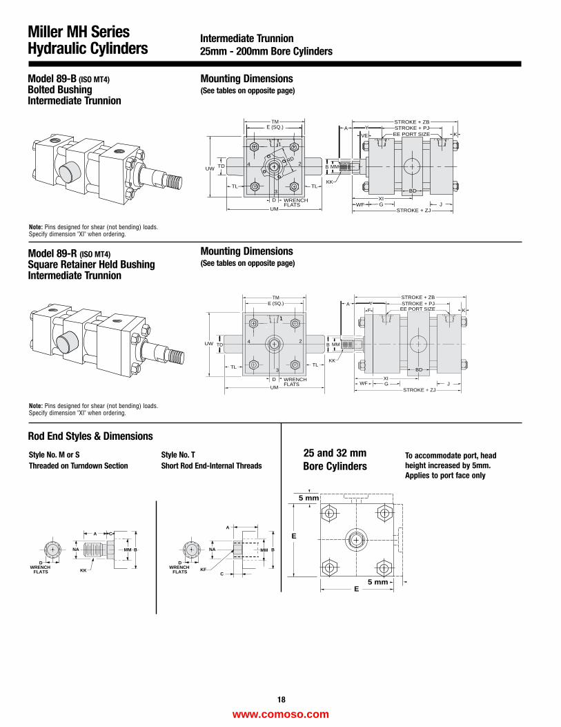
Model 89-B (ISO MT4)Bolted BushingIntermediate Trunnion
Mounting Dimensions(See tables on opposite page)
Model 89-R (ISO MT4)Square Retainer Held BushingIntermediate Trunnion
Mounting Dimensions(See tables on opposite page)
Miller MH SeriesHydraulic Cylinders
DWRENCH
FLATS
DWRENCH
FLATS
CA
NA
KKC
A
NA
KF
MM B BMM
Rod End Styles & Dimensions
Style No. M or SThreaded on Turndown Section
Style No. TShort Rod End-Internal Threads
Intermediate Trunnion 25mm - 200mm Bore Cylinders
Note: Pins designed for shear (not bending) loads.Specify dimension "XI" when ordering.
Note: Pins designed for shear (not bending) loads.Specify dimension "XI" when ordering.
STROKE + PJ
G J
STROKE + ZB
EE PORT SIZE K
STROKE + ZJ
XI
BD
Y
VE
A
KK
MMB
WF
RD
UM
TL
1
2
3
4
D WRENCHFLATS
TD
TM
UW
E (SQ.)
TL
STROKE + PJSTROKE + ZB
EE PORT SIZE
G J
KF
WF
KK
BD
YA
MM
11
2
3
4
D WRENCHFLATS
STROKE + ZJ
BTD
UM
E (SQ.)
TL
UW
TL
TM
XI
To accommodate port, headheight increased by 5mm.Applies to port face only
25 and 32 mmBore Cylinders
5 mm
5 mm
E
E
18
www.comoso.com
Miller MH SeriesHydraulic Cylinders
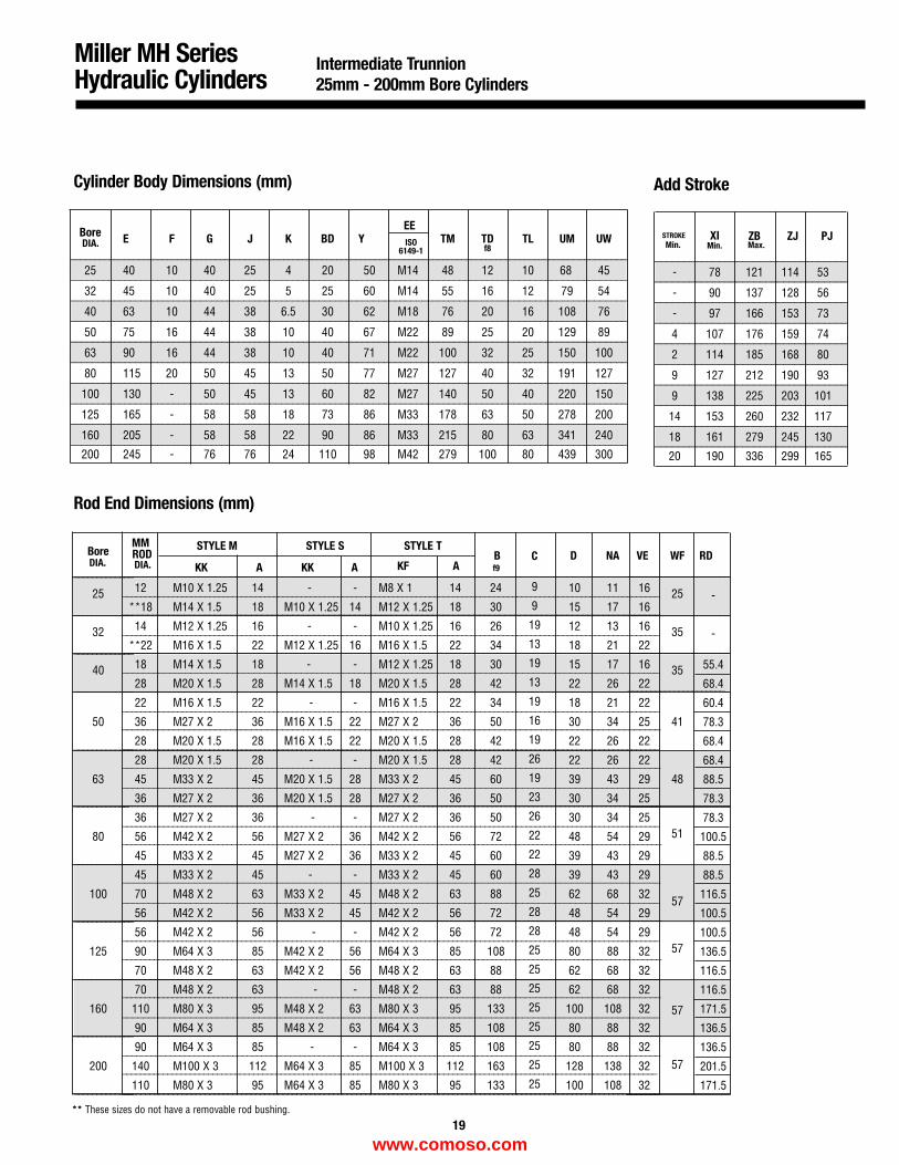
Intermediate Trunnion 25mm - 200mm Bore Cylinders
Cylinder Body Dimensions (mm)
Rod End Dimensions (mm)
** These sizes do not have a removable rod bushing.
Add Stroke
_________________________________
_________________________________
_________________________________
_________________________________
_________________________________
_________________________________
_________________________________
_________________________________
_________________________________
_________________________________
_____________________
__________________________________________________________________________________________________________________
_______________________________________________________________________________________________________
_______________________________________________________________________________________________________
_______________________________________________________________________________________________________
_______________________________________________________________________________________________________
_______________________________________________________________________________________________________
_______________________________________________________________________________________________________
_______________________________________________________________________________________________________
_______________________________________________________________________________________________________
_______________________________________________________________________________________________________
Bore E F G J K BD YEE
TM TD TL UM UWISOf86149-1
25 40 10 40 25 4 20 50 M14 48 12 10 68 45
32 45 10 40 25 5 25 60 M14 55 16 12 79 54
40 63 10 44 38 6.5 30 62 M18 76 20 16 108 76
50 75 16 44 38 10 40 67 M22 89 25 20 129 89
63 90 16 44 38 10 40 71 M22 100 32 25 150 100
80 115 20 50 45 13 50 77 M27 127 40 32 191 127
100 130 - 50 45 13 60 82 M27 140 50 40 220 150
125 165 - 58 58 18 73 86 M33 178 63 50 278 200
160 205 - 58 58 22 90 86 M33 215 80 63 341 240
200 245 - 76 76 24 110 98 M42 279 100 80 439 300
ZB ZJ PJSTROKE XI
- 78 121 114 53
- 90 137 128 56
- 97 166 153 73
4 107 176 159 74
2 114 185 168 80
9 127 212 190 93
9 138 225 203 101
14 153 260 232 117
18 161 279 245 130
20 190 336 299 165
________________________________________________________________________________________________________
________________________________________________________________________________________________________
____________________________________________________________________________________________________________________
________________________________________________________________________________________________________
________________________________________________________________________________________________________
________________________________________________________________________________________________________
______________________________________________________________________________________________________________
______________________________________________________________________________________________________________________
_________________________________________________________________________________________________
______________________________________________________________________________________________________________________
______________________________________________________________________________________________________________________
___________________________________________________________________________________________________________
___________________________________________________________________________________________________________________
______________________________________________________________________________________________________________________
_____________________________________________________________________________________________________________________
_____________________________________________________________________________________________________________________
______________________________________________________________________________________________________
_____________________________________________________________________________________________________________________
_____________________________________________________________________________________________________________________
______________________________________________________________________________________________________
________________________________________________________________________________________________________________
_____________________________________________________________________________________________________________________
MM STYLE M STYLE S STYLE TBore RODKK A KK A KF A
B D NA VE WF RD
25 12 M10 X 1.25 14 - - M8 X 1 14 24 10 11 16 25**18 M14 X 1.5 18 M10 X 1.25 14 M12 X 1.25 18 30 15 17 16
32 14 M12 X 1.25 16 - - M10 X 1.25 16 26 12 13 16 35**22 M16 X 1.5 22 M12 X 1.25 16 M16 X 1.5 22 34 18 21 22
40 18 M14 X 1.5 18 - - M12 X 1.25 18 30 15 17 16 3528 M20 X 1.5 28 M14 X 1.5 18 M20 X 1.5 28 42 22 26 22
22 M16 X 1.5 22 - - M16 X 1.5 22 34 18 21 22
50 36 M27 X 2 36 M16 X 1.5 22 M27 X 2 36 50 30 34 25 41
28 M20 X 1.5 28 M16 X 1.5 22 M20 X 1.5 28 42 22 26 22
28 M20 X 1.5 28 - - M20 X 1.5 28 42 22 26 22
63 45 M33 X 2 45 M20 X 1.5 28 M33 X 2 45 60 39 43 29 48
36 M27 X 2 36 M20 X 1.5 28 M27 X 2 36 50 30 34 25
36 M27 X 2 36 - - M27 X 2 36 50 30 34 25
80 56 M42 X 2 56 M27 X 2 36 M42 X 2 56 72 48 54 29 51
45 M33 X 2 45 M27 X 2 36 M33 X 2 45 60 39 43 29
45 M33 X 2 45 - - M33 X 2 45 60 39 43 29
100 70 M48 X 2 63 M33 X 2 45 M48 X 2 63 88 62 68 3257
56 M42 X 2 56 M33 X 2 45 M42 X 2 56 72 48 54 29
56 M42 X 2 56 - - M42 X 2 56 72 48 54 29
125 90 M64 X 3 85 M42 X 2 56 M64 X 3 85 108 80 88 32 57
70 M48 X 2 63 M42 X 2 56 M48 X 2 63 88 62 68 32
70 M48 X 2 63 - - M48 X 2 63 88 62 68 32
160 110 M80 X 3 95 M48 X 2 63 M80 X 3 95 133 100 108 32 5790 M64 X 3 85 M48 X 2 63 M64 X 3 85 108 80 88 32
90 M64 X 3 85 - - M64 X 3 85 108 80 88 32
200 140 M100 X 3 112 M64 X 3 85 M100 X 3 112 163 128 138 32 57
110 M80 X 3 95 M64 X 3 85 M80 X 3 95 133 100 108 32
______________________
______________________
______________________
______________________
Min. Max.
_____________
_____________
_____________
_____________
_____________
____________
_____________
_____________
_____________
_____________
_____________
19
-
-
55.4
68.4
60.4
78.3
68.4
68.4
88.5
78.3
78.3
100.5
88.5
88.5
116.5
100.5
100.5
136.5
116.5
116.5
171.5
136.5
136.5
201.5
171.5
DIA.
DIA. DIA. f9
Min.
C
9
9
19
13
19
13
19
16
19
26
19
23
26
22
22
28
25
28
28
25
25
25
25
25
25
25
25
www.comoso.com
CDMR
STROKE + PJ
G
K
J
STROKE + ZJY
EE PORT SIZEVEA
KK
MMB
WFL CBCW CW
STROKE + XCSTROKE + ZC
RD
D
1
2
3
4
WRENCH FLATS
E (SQ.)
CDMR
STROKE + PJ
GJ
STROKE + ZJY
EE PORT SIZEVEA
KK
MMB
WF L CBCW CW
STROKE + XCSTROKE + ZC
K
1
D
2
3
4
WRENCH FLATS
E (SQ.)
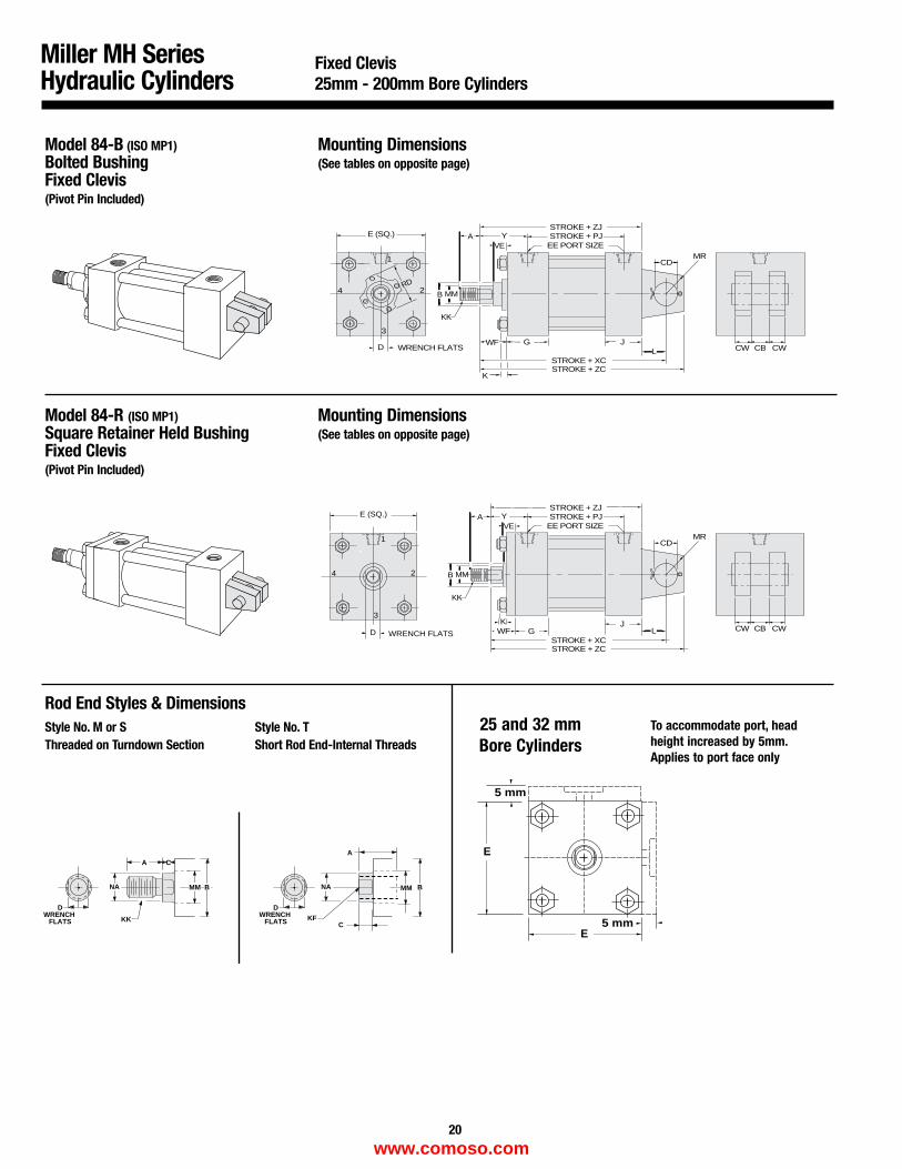
Model 84-B (ISO MP1)Bolted BushingFixed Clevis(Pivot Pin Included)
Mounting Dimensions(See tables on opposite page)
Model 84-R (ISO MP1)Square Retainer Held BushingFixed Clevis(Pivot Pin Included)
Mounting Dimensions(See tables on opposite page)
Miller MH SeriesHydraulic Cylinders
DWRENCH
FLATS
DWRENCH
FLATS
CA
NA
KKC
A
NA
KF
MM B BMM
Rod End Styles & Dimensions Style No. M or SThreaded on Turndown Section
Style No. TShort Rod End-Internal Threads
Fixed Clevis 25mm - 200mm Bore Cylinders
To accommodate port, headheight increased by 5mm.Applies to port face only
25 and 32 mmBore Cylinders
5 mm
5 mm
E
E
20
www.comoso.com
Miller MH SeriesHydraulic Cylinders
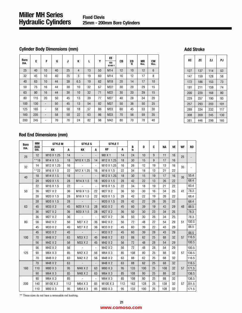
Fixed Clevis25mm - 200mm Bore Cylinders
Cylinder Body Dimensions (mm)
Rod End Dimensions (mm)
** These sizes do not have a removable rod bushing.
Add Stroke
__________________________________________________________________________________________________________________
_______________________________________________________________________________________________________
_______________________________________________________________________________________________________
_______________________________________________________________________________________________________
_______________________________________________________________________________________________________
_______________________________________________________________________________________________________
_______________________________________________________________________________________________________
_______________________________________________________________________________________________________
_______________________________________________________________________________________________________
_______________________________________________________________________________________________________
Bore E F G J K L YEE
CB CD MR CWISO6149-1
f8 Max. Max.
25 40 10 40 25 4 13 50 M14 12 10 12 6
32 45 10 40 25 5 19 60 M14 16 12 17 8
40 63 10 44 38 6.5 19 62 M18 20 14 17 10
50 75 16 44 38 10 32 67 M22 30 20 29 15
63 90 16 44 38 10 32 71 M22 30 20 29 15
80 115 20 50 45 13 39 77 M27 40 28 34 20
100 130 - 50 45 13 54 82 M27 50 36 50 25
125 165 - 58 58 18 57 86 M33 60 45 53 30
160 205 - 58 58 22 63 86 M33 70 56 59 35
200 245 - 76 76 24 82 98 M42 80 70 78 40
___________________________
___________________________
___________________________
___________________________
___________________________
___________________________
___________________________
___________________________
___________________________
___________________________
XC ZC ZJ PJ
127 137 114 53
147 159 128 56
172 186 153 73
191 211 159 74
200 220 168 80
229 257 190 93
257 293 203 101
289 334 232 117
308 359 245 130
381 446 299 165
______________________________________________________________________________________________
______________________________________________________________________________________________
______________________________________________________________________________________________________
__________________________________________________________________________________________________
_______________________________________________________________________________________________
______________________________________________________________________________________________
______________________________________________________________________________________________
_______________________________________________________________________________________________________
__________________________________________________________________________________________________________
__________________________________________________________________________________________________________
__________________________________________________________________________________________________________
__________________________________________________________________________________________________________
__________________________________________________________________________________________________________
__________________________________________________________________________________________________________
______________________________________________________________________________________________________________
______________________________________________________________________________________________________________
______________________________________________________________________________________________________________
______________________________________________________________________________________________________________
______________________________________________________________________________________________________________
______________________________________________________________________________________________________________
______________________________________________________________________________________________________________
______________________________________________________________________________________________________________
______________________________________________________________________________________________________________
______________________________________________________________________________________________________________
______________________________________________________________________________________________________________
______________________________________________________________________________________________________________
______________________________________________________________________________________________________________
__________________________________________________________________________________________________________
_____________
_____________
_____________
_____________
_____________
____________
_____________
_____________
_____________
MM STYLE M STYLE S STYLE TBoreROD
KK A KK A KF AB D NA VE WF RD
25 12 M10 X 1.25 14 - - M8 X 1 14 24 10 11 16 25**18 M14 X 1.5 18 M10 X 1.25 14 M12 X 1.25 18 30 15 17 16
32 14 M12 X 1.25 16 - - M10 X 1.25 16 26 12 13 16 35**22 M16 X 1.5 22 M12 X 1.25 16 M16 X 1.5 22 34 18 21 22
40 18 M14 X 1.5 18 - - M12 X 1.25 18 30 15 17 16 3528 M20 X 1.5 28 M14 X 1.5 18 M20 X 1.5 28 42 22 26 22
22 M16 X 1.5 22 - - M16 X 1.5 22 34 18 21 22
50 36 M27 X 2 36 M16 X 1.5 22 M27 X 2 36 50 30 34 25 41
28 M20 X 1.5 28 M16 X 1.5 22 M20 X 1.5 28 42 22 26 22
28 M20 X 1.5 28 - - M20 X 1.5 28 42 22 26 22
63 45 M33 X 2 45 M20 X 1.5 28 M33 X 2 45 60 39 43 29 48
36 M27 X 2 36 M20 X 1.5 28 M27 X 2 36 50 30 34 25
36 M27 X 2 36 - - M27 X 2 36 50 30 34 25
80 56 M42 X 2 56 M27 X 2 36 M42 X 2 56 72 48 54 29 51
45 M33 X 2 45 M27 X 2 36 M33 X 2 45 60 39 43 29
45 M33 X 2 45 - - M33 X 2 45 60 39 43 29
100 70 M48 X 2 63 M33 X 2 45 M48 X 2 63 88 62 68 32 57
56 M42 X 2 56 M33 X 2 45 M42 X 2 56 72 48 54 29
56 M42 X 2 56 - - M42 X 2 56 72 48 54 29
125 90 M64 X 3 85 M42 X 2 56 M64 X 3 85 108 80 88 32 57
70 M48 X 2 63 M42 X 2 56 M48 X 2 63 88 62 68 32
70 M48 X 2 63 - - M48 X 2 63 88 62 68 32
160 110 M80 X 3 95 M48 X 2 63 M80 X 3 95 133 100 108 32 57
90 M64 X 3 85 M48 X 2 63 M64 X 3 85 108 80 88 32
90 M64 X 3 85 - - M64 X 3 85 108 80 88 32
200 140 M100 X 3 112 M64 X 3 85 M100 X 3 112 163 128 138 32 57
110 M80 X 3 95 M64 X 3 85 M80 X 3 95 133 100 108 32
f9
21
-
-
55.4
68.4
60.4
78.3
68.4
68.4
88.5
78.3
78.3100.5
88.5
88.5116.5
100.5
100.5
136.5
116.5
116.5
171.5
136.5
136.5
201.5
171.5
DIA.
DIA. DIA.C
9
9
19
13
19
13
19
16
19
26
19
23
26
22
22
28
25
28
28
25
25
25
25
25
25
25
25
www.comoso.com
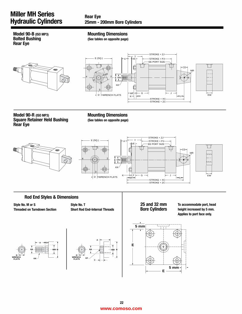
EW
A
KK
MMB
STROKE + PJEE PORT SIZE
VEY
CD
G JWFL
MR
STROKE + LBSTROKE + XCSTROKE + ZC
D
1
2
3
4
WRENCH FLATS
E (SQ.)
K
RD
STROKE + ZJ
Model 90-B (ISO MP3)Bolted BushingRear Eye
Mounting Dimensions(See tables on opposite page)
Model 90-R (ISO MP3)Square Retainer Held BushingRear Eye
Mounting Dimensions(See tables on opposite page)
Miller MH SeriesHydraulic Cylinders
DWRENCH
FLATS
DWRENCH
FLATS
CA
NA
KKC
A
NA
KF
MM B BMM
Rod End Styles & Dimensions
Style No. M or SThreaded on Turndown Section
Style No. TShort Rod End-Internal Threads
Rear Eye25mm - 200mm Bore Cylinders
Y
VEA
KK
MMB
STROKE + PJ
G J
EE PORT SIZE
CD
FWF L
STROKE + XC
1
D
2
3
4
WRENCH FLATS
E (SQ.)
K EW
STROKE + ZJ
MR
STROKE + ZC
25 and 32 mmBore Cylinders
To accommodate port, head height increased by 5 mm.Applies to port face only.
5 mm
5 mm
E
E
22
www.comoso.com
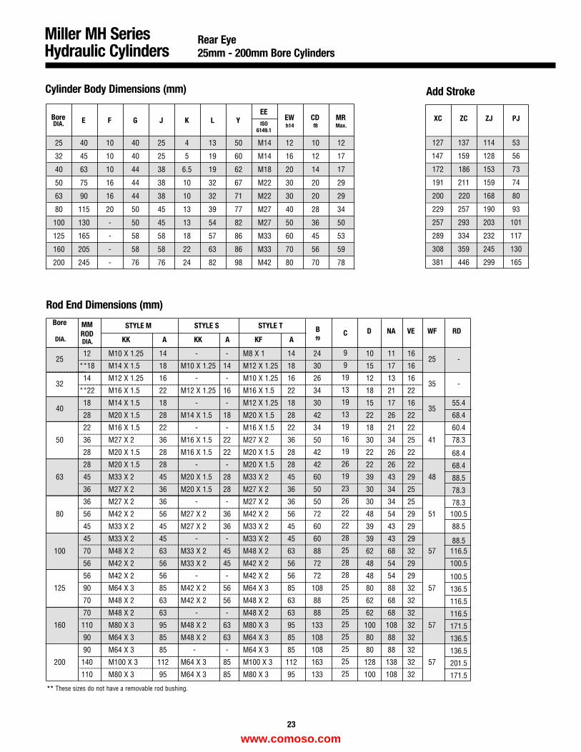
Miller MH SeriesHydraulic Cylinders
Rear Eye25mm - 200mm Bore Cylinders
** These sizes do not have a removable rod bushing.
Rod End Dimensions (mm)
Cylinder Body Dimensions (mm) Add Stroke
___________________________
___________________________
___________________________
___________________________
___________________________
___________________________
___________________________
___________________________
___________________________
___________________________
Bore E F G J K L YEE
EW CD MRISO
6149.1h14 f8 Max.
25 40 10 40 25 4 13 50 M14 12 10 12
32 45 10 40 25 5 19 60 M14 16 12 17
40 63 10 44 38 6.5 19 62 M18 20 14 17
50 75 16 44 38 10 32 67 M22 30 20 29
63 90 16 44 38 10 32 71 M22 30 20 29
80 115 20 50 45 13 39 77 M27 40 28 34
100 130 - 50 45 13 54 82 M27 50 36 50
125 165 - 58 58 18 57 86 M33 60 45 53
160 205 - 58 58 22 63 86 M33 70 56 59
200 245 - 76 76 24 82 98 M42 80 70 78
XC ZC ZJ PJ
127 137 114 53
147 159 128 56
172 186 153 73
191 211 159 74
200 220 168 80
229 257 190 93
257 293 203 101
289 334 232 117
308 359 245 130
381 446 299 165
___________________________________________________________________________________________________
___________________________________________________________________________________________________
____________________________________________________________________________________________________________
_____________________________________________________________________________________________________
___________________________________________________________________________________________________
___________________________________________________________________________________________________
_____________________________________________________________________________________________________
_______________________________________________________________________________________________________________
_______________________________________________________________________________________________________________
_______________________________________________________________________________________________________________
_______________________________________________________________________________________________________________
_______________________________________________________________________________________________________________
_______________________________________________________________________________________________________________
_______________________________________________________________________________________________________________
_
____________________________________________________________________________________________________________________
____________________________________________________________________________________________________________________
________________________________________________________________________________________________________
____________________________________________________________________________________________________________________
____________________________________________________________________________________________________________________
________________________________________________________________________________________________________
____________________________________________________________________________________________________________________
_
_____________
_____________
_____________
_____________
_____________
____________
_____________
_____________
_____________
MM STYLE M STYLE S STYLE T BBore
RODKK A KK A KF A f9
D NA VE WF RD
2512 M10 X 1.25 14 - - M8 X 1 14 24 10 11 16
25**18 M14 X 1.5 18 M10 X 1.25 14 M12 X 1.25 18 30 15 17 16
3214 M12 X 1.25 16 - - M10 X 1.25 16 26 12 13 16
35**22 M16 X 1.5 22 M12 X 1.25 16 M16 X 1.5 22 34 18 21 22
4018 M14 X 1.5 18 - - M12 X 1.25 18 30 15 17 16
3528 M20 X 1.5 28 M14 X 1.5 18 M20 X 1.5 28 42 22 26 22
22 M16 X 1.5 22 - - M16 X 1.5 22 34 18 21 22
50 36 M27 X 2 36 M16 X 1.5 22 M27 X 2 36 50 30 34 25 41
28 M20 X 1.5 28 M16 X 1.5 22 M20 X 1.5 28 42 22 26 22
28 M20 X 1.5 28 - - M20 X 1.5 28 42 22 26 22
63 45 M33 X 2 45 M20 X 1.5 28 M33 X 2 45 60 39 43 29 48
36 M27 X 2 36 M20 X 1.5 28 M27 X 2 36 50 30 34 25
36 M27 X 2 36 - - M27 X 2 36 50 30 34 25
80 56 M42 X 2 56 M27 X 2 36 M42 X 2 56 72 48 54 29 51
45 M33 X 2 45 M27 X 2 36 M33 X 2 45 60 39 43 29
45 M33 X 2 45 - - M33 X 2 45 60 39 43 29
100 70 M48 X 2 63 M33 X 2 45 M48 X 2 63 88 62 68 32 57
56 M42 X 2 56 M33 X 2 45 M42 X 2 56 72 48 54 29
56 M42 X 2 56 - - M42 X 2 56 72 48 54 29
125 90 M64 X 3 85 M42 X 2 56 M64 X 3 85 108 80 88 32 57
70 M48 X 2 63 M42 X 2 56 M48 X 2 63 88 62 68 32
70 M48 X 2 63 - - M48 X 2 63 88 62 68 32
160 110 M80 X 3 95 M48 X 2 63 M80 X 3 95 133 100 108 32 57
90 M64 X 3 85 M48 X 2 63 M64 X 3 85 108 80 88 32
90 M64 X 3 85 - - M64 X 3 85 108 80 88 32
200 140 M100 X 3 112 M64 X 3 85 M100 X 3 112 163 128 138 32 57
110 M80 X 3 95 M64 X 3 85 M80 X 3 95 133 100 108 32
23
-
-
55.4
68.4
60.4
78.3
68.4
68.4
88.5
78.3
78.3100.5
88.5
88.5116.5
100.5
100.5
136.5
116.5
116.5
171.5
136.5
136.5
201.5
171.5
DIA.
DIA. DIA.C
9
9
19
13
19
13
19
16
19
26
19
23
26
22
22
28
25
28
28
25
25
25
25
25
25
25
25
www.comoso.com
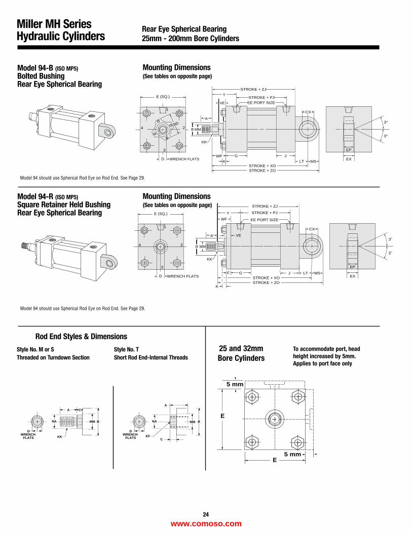
Model 94-B (ISO MP5)Bolted BushingRear Eye Spherical Bearing
Mounting Dimensions(See tables on opposite page)
Model 94-R (ISO MP5)Square Retainer Held BushingRear Eye Spherical Bearing
Mounting Dimensions(See tables on opposite page)
Miller MH SeriesHydraulic Cylinders
Rear Eye Spherical Bearing25mm - 200mm Bore Cylinders
Model 94 should use Spherical Rod Eye on Rod End. See Page 29.
Model 94 should use Spherical Rod Eye on Rod End. See Page 29.
DWRENCH
FLATS
DWRENCH
FLATS
CA
NA
KKC
A
NA
KF
MM B BMM
Rod End Styles & Dimensions
Style No. M or SThreaded on Turndown Section
Style No. TShort Rod End-Internal Threads
25 and 32mmBore Cylinders
To accommodate port, head height increased by 5mm.Applies to port face only
5 mm
5 mm
E
E
24
A
MMB
Y
CX
G J LT MSSTROKE + XOSTROKE + ZO
D
1
2
3
4
WRENCH FLATS
E (SQ.)
K
FEX
KK
3
3
EP
WF
VE
STROKE + PJ
EE PORT SIZE
STROKE + ZJ
A
MMB
YSTROKE + PJ
EE PORT SIZEVE
CX
G J
LT MSSTROKE + XOSTROKE + ZO
D
1
2
3
4
WRENCH FLATS
E (SQ.)
K
RD
EX
KK
3°
3°
EP
STROKE + ZJ
WF
www.comoso.com
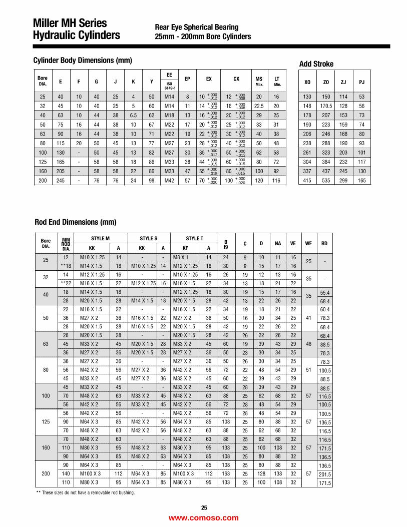
Miller MH SeriesHydraulic Cylinders
Rear Eye Spherical Bearing25mm - 200mm Bore Cylinders
** These sizes do not have a removable rod bushing.
Cylinder Body Dimensions (mm) Add Stroke
Rod End Dimensions (mm)
__________________________________________________________________________________________________________________
_______________________________________________________________________________________________________
_______________________________________________________________________________________________________
_______________________________________________________________________________________________________
_______________________________________________________________________________________________________
_______________________________________________________________________________________________________
_______________________________________________________________________________________________________
_______________________________________________________________________________________________________
_______________________________________________________________________________________________________
_______________________________________________________________________________________________________
BoreE F G J K Y
EEEP EX CX MS LT
ISO Max. Min.6149-1
25 40 10 40 25 4 50 M14 8 10 12 20 16
32 45 10 40 25 5 60 M14 11 14 16 22.5 20
40 63 10 44 38 6.5 62 M18 13 16 20 29 25
50 75 16 44 38 10 67 M22 17 20 25 33 31
63 90 16 44 38 10 71 M22 19 22 30 40 38
80 115 20 50 45 13 77 M27 23 28 40 50 48
100 130 - 50 45 13 82 M27 30 35 50 62 58
125 165 - 58 58 18 86 M33 38 44 60 80 72
160 205 - 58 58 22 86 M33 47 55 80 100 92
200 245 - 76 76 24 98 M42 57 70 100 120 116
___________________________
___________________________
___________________________
___________________________
___________________________
___________________________
___________________________
___________________________
___________________________
___________________________
XO ZO ZJ PJ
130 150 114 53
148 170.5 128 56
178 207 153 73
190 223 159 74
206 246 168 80
238 288 190 93
261 323 203 101
304 384 232 117
337 437 245 130
415 535 299 165
_____________________________________________________________________________________________________
_____________________________________________________________________________________________________
______________________________________________________________________________________________________________
______________________________________________________________________________________________________
_____________________________________________________________________________________________________
_____________________________________________________________________________________________________
_______________________________________________________________________________________________________
________________________________________________________________________________________________________________
________________________________________________________________________________________________________________
________________________________________________________________________________________________________________
________________________________________________________________________________________________________________
________________________________________________________________________________________________________________
________________________________________________________________________________________________________________
________________________________________________________________________________________________________________
_
_____________________________________________________________________________________________________________________
_____________________________________________________________________________________________________________________
_____________________________________________________________________________________________________________________
__________________________________________________________________________________________________
_____________________________________________________________________________________________________________________
_____________________________________________________________________________________________________________________
_____________________________________________________________________________________________________________________
___________________________________________________________________________________________________
_____________________________________________________________________________________________________________________
_
_____________
_____________
_____________
_____________
_____________
____________
_____________
_____________
_____________
MM STYLE M STYLE S STYLE TBoreROD
KK A KK A KF AB D NA VE WF RD
25 12 M10 X 1.25 14 - - M8 X 1 14 24 10 11 1625
**18 M14 X 1.5 18 M10 X 1.25 14 M12 X 1.25 18 30 15 17 16
32 14 M12 X 1.25 16 - - M10 X 1.25 16 26 12 13 1635
**22 M16 X 1.5 22 M12 X 1.25 16 M16 X 1.5 22 34 18 21 22
40 18 M14 X 1.5 18 - - M12 X 1.25 18 30 15 17 1635
28 M20 X 1.5 28 M14 X 1.5 18 M20 X 1.5 28 42 22 26 22
22 M16 X 1.5 22 - - M16 X 1.5 22 34 18 21 22
50 36 M27 X 2 36 M16 X 1.5 22 M27 X 2 36 50 30 34 25 41
28 M20 X 1.5 28 M16 X 1.5 22 M20 X 1.5 28 42 22 26 22
28 M20 X 1.5 28 - - M20 X 1.5 28 42 22 26 22
63 45 M33 X 2 45 M20 X 1.5 28 M33 X 2 45 60 39 43 29 48
36 M27 X 2 36 M20 X 1.5 28 M27 X 2 36 50 30 34 25
36 M27 X 2 36 - - M27 X 2 36 50 30 34 25
80 56 M42 X 2 56 M27 X 2 36 M42 X 2 56 72 48 54 29 51
45 M33 X 2 45 M27 X 2 36 M33 X 2 45 60 39 43 29
45 M33 X 2 45 - - M33 X 2 45 60 39 43 29
100 70 M48 X 2 63 M33 X 2 45 M48 X 2 63 88 62 68 32 57
56 M42 X 2 56 M33 X 2 45 M42 X 2 56 72 48 54 29
56 M42 X 2 56 - - M42 X 2 56 72 48 54 29
125 90 M64 X 3 85 M42 X 2 56 M64 X 3 85 108 80 88 32 57
70 M48 X 2 63 M42 X 2 56 M48 X 2 63 88 62 68 32
70 M48 X 2 63 - - M48 X 2 63 88 62 68 32
160 110 M80 X 3 95 M48 X 2 63 M80 X 3 95 133 100 108 32 57
90 M64 X 3 85 M48 X 2 63 M64 X 3 85 108 80 88 32
90 M64 X 3 85 - - M64 X 3 85 108 80 88 32
200 140 M100 X 3 112 M64 X 3 85 M100 X 3 112 163 128 138 32 57
110 M80 X 3 95 M64 X 3 85 M80 X 3 95 133 100 108 32
+.000-.012
+.000-.012
+.000-.012
+.000-.012
+.000-.012
+.000-.012
+.000-.012
+.000-.015
+.000-.015
+.000-.020
+.000-.008
+.000-.008
+.000-.012
+.000-.012
+.000-.012
+.000-.012
+.000-.012
+.000-.015
+.000-.015+.000-.020
25
-
-
55.4
68.460.4
78.3
68.4
68.4
88.5
78.3
78.3
100.5
88.5
88.5116.5100.5
100.5
136.5
116.5
116.5
171.5
136.5
136.5
201.5
171.5
DIA.
DIA.DIA. f9
C
9
9
19
13
19
13
19
16
19
26
19
23
26
22
22
28
25
28
28
25
25
25
25
25
25
25
25
www.comoso.com
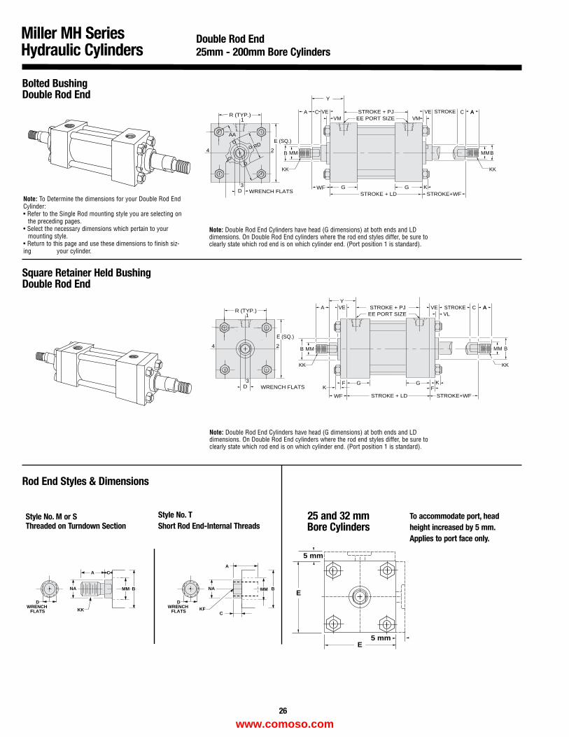
RD
STROKE + PJ
G GWF
EE PORT SIZE
KSTROKE + LD
KK
D
R (TYP.)1
2
3
4
WRENCH FLATS
AAE (SQ.)
C VEVM
VE STROKEVM
KK
BMM
C AA
B MM
A
STROKE+WF
Y
Bolted BushingDouble Rod End
Square Retainer Held Bushing Double Rod End
Miller MH SeriesHydraulic Cylinders
26
Rod End Styles & Dimensions
Double Rod End25mm - 200mm Bore Cylinders
Note: Double Rod End Cylinders have head (G dimensions) at both ends and LDdimensions. On Double Rod End cylinders where the rod end styles differ, be sure toclearly state which rod end is on which cylinder end. (Port position 1 is standard).
DWRENCH
FLATS
DWRENCH
FLATS
CA
NA
KKC
A
NA
KF
MM B BMM
5 mm
5 mm
E
E
Style No. M or SThreaded on Turndown Section
Style No. TShort Rod End-Internal Threads
25 and 32 mmBore Cylinders
To accommodate port, head height increased by 5 mm.Applies to port face only.
Note: To Determine the dimensions for your Double Rod EndCylinder:• Refer to the Single Rod mounting style you are selecting on
the preceding pages.• Select the necessary dimensions which pertain to your
mounting style.• Return to this page and use these dimensions to finish siz-ing your cylinder.
Note: Double Rod End Cylinders have head (G dimensions) at both ends and LDdimensions. On Double Rod End cylinders where the rod end styles differ, be sure toclearly state which rod end is on which cylinder end. (Port position 1 is standard).
F
WF
STROKE + PJ
G G
EE PORT SIZE
KK
STROKE + LD
KK
D
1
2
3
4
WRENCH FLATS
E (SQ.)
VE VE STROKEVL
KK
BMM
C AA
B MM
A
F
STROKE+WF
Y
R (TYP.)
www.comoso.com
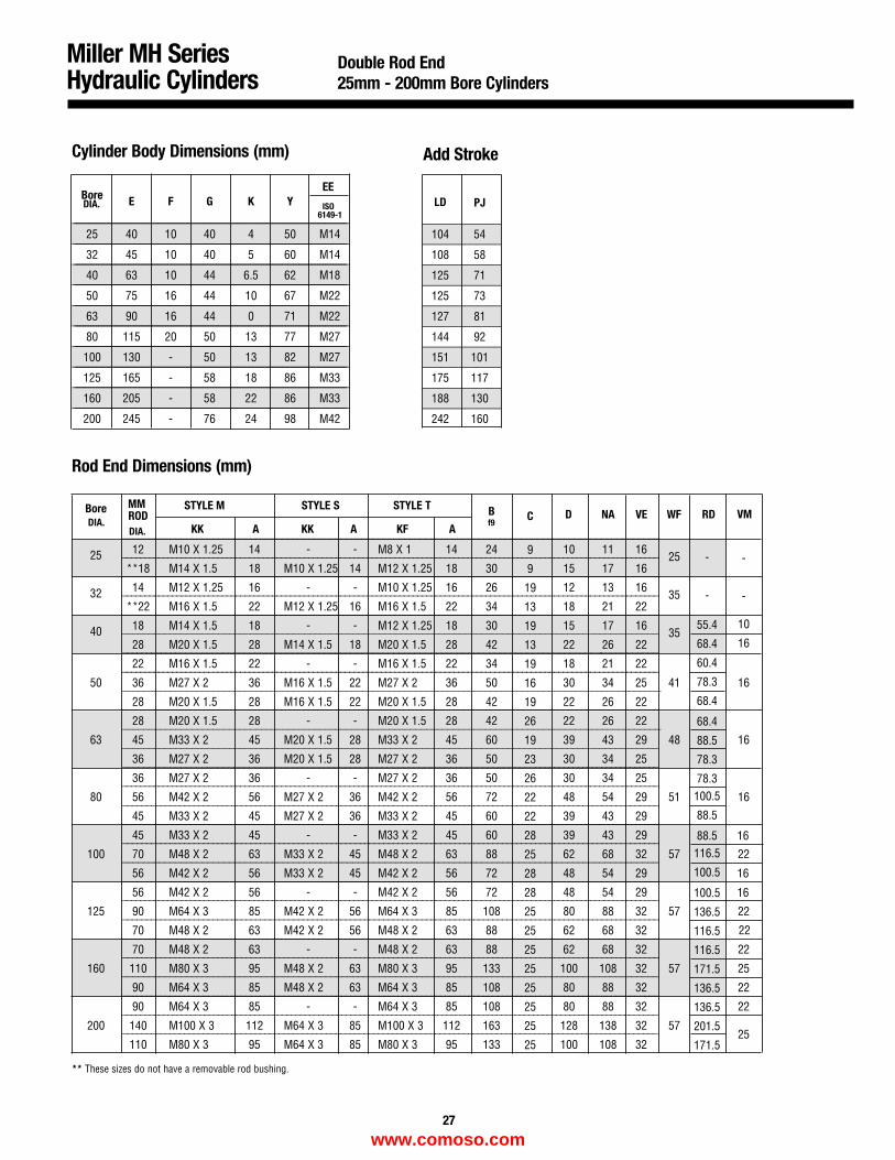
Miller MH SeriesHydraulic Cylinders
Double Rod End25mm - 200mm Bore Cylinders
Cylinder Body Dimensions (mm)
Rod End Dimensions (mm)
Add Stroke
** These sizes do not have a removable rod bushing.
__________________________________________________________________________________________________________________
_______________________________________________________________________________________________________
_______________________________________________________________________________________________________
_______________________________________________________________________________________________________
_______________________________________________________________________________________________________
_______________________________________________________________________________________________________
_______________________________________________________________________________________________________
_______________________________________________________________________________________________________
_______________________________________________________________________________________________________
_______________________________________________________________________________________________________
Bore E F G K YEE
ISO6149-1
25 40 10 40 4 50 M14
32 45 10 40 5 60 M14
40 63 10 44 6.5 62 M18
50 75 16 44 10 67 M22
63 90 16 44 0 71 M22
80 115 20 50 13 77 M27
100 130 - 50 13 82 M27
125 165 - 58 18 86 M33
160 205 - 58 22 86 M33
200 245 - 76 24 98 M42
_____________
_____________
_____________
_____________
_____________
_____________
_____________
_____________
_____________
_____________
LD PJ
104 54
108 58
125 71
125 73
127 81
144 92
151 101
175 117
188 130
242 160
_____________________________________________________________________________________________________
_____________________________________________________________________________________________________
______________________________________________________________________________________________________________
______________________________________________________________________________________________________
_____________________________________________________________________________________________________
_____________________________________________________________________________________________________
________________________________________________________________________________________________________
_________________________________________________________________________________________________________________
_________________________________________________________________________________________________________________
_________________________________________________________________________________________________________________
_________________________________________________________________________________________________________________
_________________________________________________________________________________________________________________
_________________________________________________________________________________________________________________
_________________________________________________________________________________________________________________
______________________________________________________________________________________________________________________
______________________________________________________________________________________________________________________
____________________________________________________________________________________________________
______________________________________________________________________________________________________________________
______________________________________________________________________________________________________________________
____________________________________________________________________________________________________
_____________________________________________________________________________________________________________________
_
MM STYLE M STYLE S STYLE T BBoreROD
KK A KK A KF Af9
D NA VE WF RD
25 12 M10 X 1.25 14 - - M8 X 1 14 24 10 11 1625
**18 M14 X 1.5 18 M10 X 1.25 14 M12 X 1.25 18 30 15 17 16
32 14 M12 X 1.25 16 - - M10 X 1.25 16 26 12 13 1635
**22 M16 X 1.5 22 M12 X 1.25 16 M16 X 1.5 22 34 18 21 22
40 18 M14 X 1.5 18 - - M12 X 1.25 18 30 15 17 1635
28 M20 X 1.5 28 M14 X 1.5 18 M20 X 1.5 28 42 22 26 22
22 M16 X 1.5 22 - - M16 X 1.5 22 34 18 21 22
50 36 M27 X 2 36 M16 X 1.5 22 M27 X 2 36 50 30 34 25 41
28 M20 X 1.5 28 M16 X 1.5 22 M20 X 1.5 28 42 22 26 22
28 M20 X 1.5 28 - - M20 X 1.5 28 42 22 26 22
63 45 M33 X 2 45 M20 X 1.5 28 M33 X 2 45 60 39 43 29 48
36 M27 X 2 36 M20 X 1.5 28 M27 X 2 36 50 30 34 25
36 M27 X 2 36 - - M27 X 2 36 50 30 34 25
80 56 M42 X 2 56 M27 X 2 36 M42 X 2 56 72 48 54 29 51
45 M33 X 2 45 M27 X 2 36 M33 X 2 45 60 39 43 29
45 M33 X 2 45 - - M33 X 2 45 60 39 43 29
100 70 M48 X 2 63 M33 X 2 45 M48 X 2 63 88 62 68 32 57
56 M42 X 2 56 M33 X 2 45 M42 X 2 56 72 48 54 29
56 M42 X 2 56 - - M42 X 2 56 72 48 54 29
125 90 M64 X 3 85 M42 X 2 56 M64 X 3 85 108 80 88 32 57
70 M48 X 2 63 M42 X 2 56 M48 X 2 63 88 62 68 32
70 M48 X 2 63 - - M48 X 2 63 88 62 68 32
160 110 M80 X 3 95 M48 X 2 63 M80 X 3 95 133 100 108 32 57
90 M64 X 3 85 M48 X 2 63 M64 X 3 85 108 80 88 32
90 M64 X 3 85 - - M64 X 3 85 108 80 88 32
200 140 M100 X 3 112 M64 X 3 85 M100 X 3 112 163 128 138 32 57
110 M80 X 3 95 M64 X 3 85 M80 X 3 95 133 100 108 32
27
-
-
55.4
68.4
60.4
78.3
68.4
68.4
88.5
78.3
78.3100.5
88.5
88.5116.5
100.5
100.5
136.5
116.5
116.5
171.5
136.5
136.5
201.5
171.5
DIA.
DIA.DIA.
C
9
9
19
13
19
13
19
16
19
26
19
23
26
22
22
28
25
28
28
25
25
25
25
25
25
25
25
-
-
10
16
16
16
16
22
22
22
25
22
22
25
VM
22
16
16
16
www.comoso.com
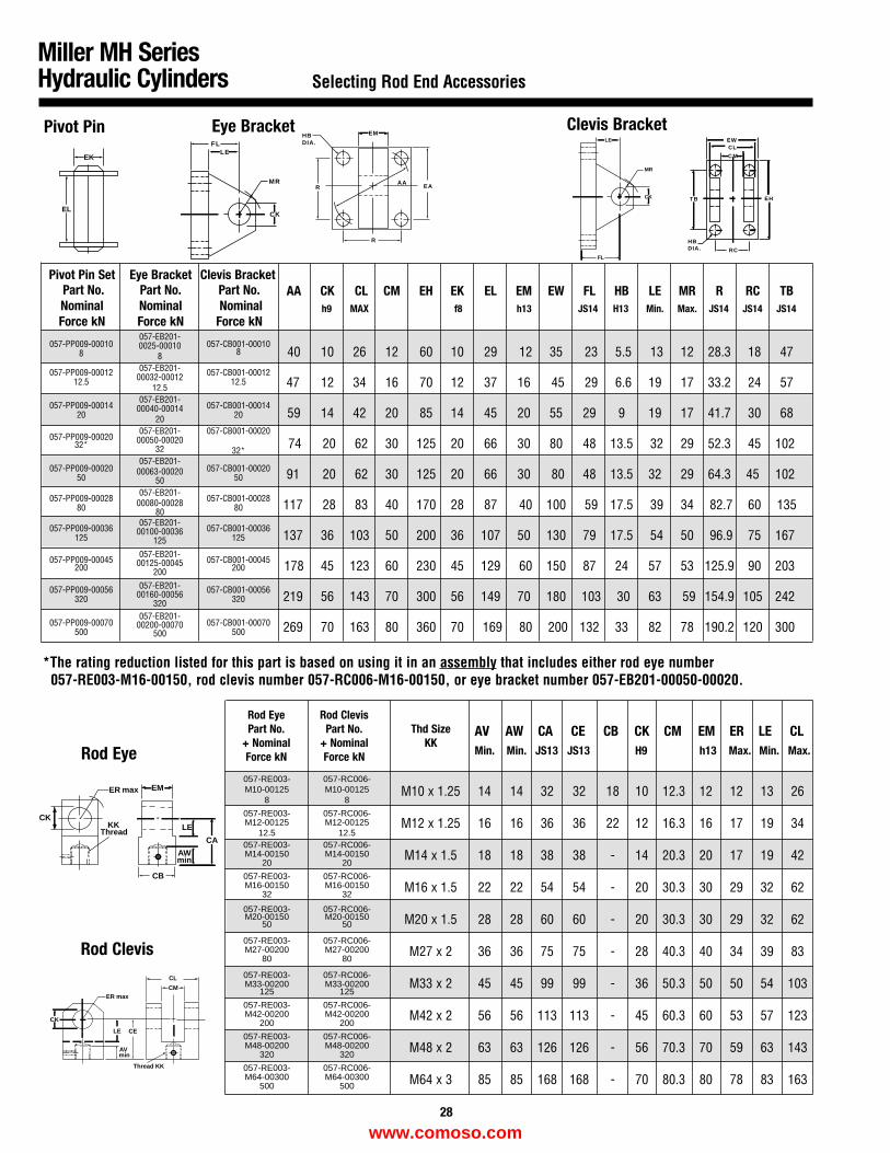
FLLE
MR
CK
*The rating reduction listed for this part is based on using it in an assembly that includes either rod eye number057-RE003-M16-00150, rod clevis number 057-RC006-M16-00150, or eye bracket number 057-EB201-00050-00020.
Miller MH SeriesHydraulic Cylinders Selecting Rod End Accessories
Pivot Pin Set Eye Bracket Clevis BracketPart No. Part No. Part No.Nominal Nominal NominalForce kN Force kN Force kN
AA CK CL CM EH EK EL EM EW FL HB LE MR R RC TB
40 10 26 12 60 10 29 12 35 23 5.5 13 12 28.3 18 47
47 12 34 16 70 12 37 16 45 29 6.6 19 17 33.2 24 57
59 14 42 20 85 14 45 20 55 29 9 19 17 41.7 30 68
74 20 62 30 125 20 66 30 80 48 13.5 32 29 52.3 45 102
91 20 62 30 125 20 66 30 80 48 13.5 32 29 64.3 45 102
117 28 83 40 170 28 87 40 100 59 17.5 39 34 82.7 60 135
137 36 103 50 200 36 107 50 130 79 17.5 54 50 96.9 75 167
178 45 123 60 230 45 129 60 150 87 24 57 53 125.9 90 203
219 56 143 70 300 56 149 70 180 103 30 63 59 154.9 105 242
269 70 163 80 360 70 169 80 200 132 33 82 78 190.2 120 300
M10 x 1.25 14 14 32 32 18 10 12.3 12 12 13 26
M12 x 1.25 16 16 36 36 22 12 16.3 16 17 19 34
M14 x 1.5 18 18 38 38 - 14 20.3 20 17 19 42
M16 x 1.5 22 22 54 54 - 20 30.3 30 29 32 62
M20 x 1.5 28 28 60 60 - 20 30.3 30 29 32 62
M27 x 2 36 36 75 75 - 28 40.3 40 34 39 83
M33 x 2 45 45 99 99 - 36 50.3 50 50 54 103
M42 x 2 56 56 113 113 - 45 60.3 60 53 57 123
M48 x 2 63 63 126 126 - 56 70.3 70 59 63 143
M64 x 3 85 85 168 168 - 70 80.3 80 78 83 163
057-PP009-00010057-EB201-
057-CB001-000100025-000108 8 8
057-PP009-00012 057-EB201- 057-CB001-0001200032-0001212.512.5
12.5
057-PP009-00014057-EB201-
057-CB001-0001400040-0001420 20 20
057-PP009-00020057-EB201- 057-CB001-00020
00050-0002032* 32 32*
057-PP009-00020057-EB201-
057-CB001-0002000063-0002050 50 50
057-PP009-00028057-EB201-
057-CB001-0002800080-0002880 80 80
057-PP009-00036057-EB201-
057-CB001-0003600100-00036125 125 125
057-PP009-00045057-EB201-
057-CB001-0004500125-00045200 200 200
057-PP009-00056 057-EB201- 057-CB001-0005600160-00056320 320 320
057-PP009-00070057-EB201-
057-CB001-0007000200-00070500 500 500
057-RE003- 057-RC006-M10-00125 M10-00125
8 8
057-RE003- 057-RC006-M12-00125 M12-00125
12.5 12.5057-RE003- 057-RC006-M14-00150 M14-00150
20 20
057-RE003- 057-RC006-M16-00150 M16-00150
32 32
057-RE003- 057-RC006-M20-00150 M20-00150
50 50
057-RE003- 057-RC006-M27-00200 M27-00200
80 80
057-RE003- 057-RC006-M33-00200 M33-00200
125 125
057-RE003- 057-RC006-M42-00200 M42-00200
200 200
057-RE003- 057-RC006-M48-00200 M48-00200
320 320
057-RE003- 057-RC006-M64-00300 M64-00300
500 500
EK
EL
+ +
+ +
EH
RC
HBDIA.
TB
C M
CLEW
Pivot Pin
+ +
+ +
EMHBDIA.
R
R
AAEA
Eye Bracket
FL
LE
MR
CK
Clevis Bracket
+
ER
CKKK
Thread
max EM
+
LE
CA
CB
AWmin
Rod Eye
AVmin
LE
ER max
CK
CE
CL
CM
Thread KK
Rod Clevis
h9 MAX f8 h13 JS14 H13 Min. Max. JS14 JS14 JS14
28
AV AW CA CE CB CK CM EM ER LE CLMin. Min. JS13 JS13 H9 h13 Max. Min. Max.
Rod Eye Rod ClevisPart No. Part No. Thd Size
+ Nominal + Nominal KKForce kN Force kN
www.comoso.com
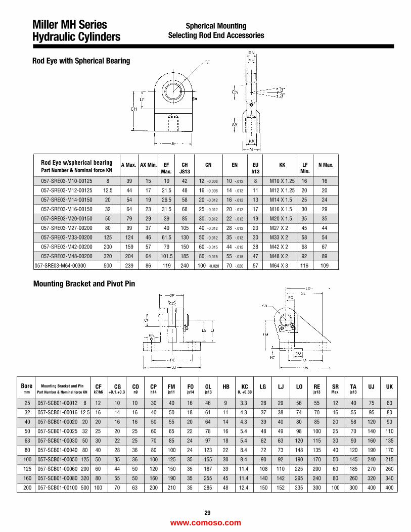
Miller MH SeriesHydraulic Cylinders
Spherical MountingSelecting Rod End Accessories
Rod Eye with Spherical Bearing
Mounting Bracket and Pivot Pin
Rod Eye w/spherical bearing A Max. AX Min. EF CH CN EN EU KK LFMin.
N Max.Part Number & Nominal force KN Max. JS13 h13
057-SRE03-M10-00125 8 39 15 19 42 12 -0.008 10 -.012 8 M10 X 1.25 16 16
057-SRE03-M12-00125 12.5 44 17 21.5 48 16 -0.008 14 -.012 11 M12 X 1.25 20 20
057-SRE03-M14-00150 20 54 19 26.5 58 20 -0.012 16 -.012 13 M14 X 1.5 25 24
057-SRE03-M16-00150 32 64 23 31.5 68 25 -0.012 20 -.012 17 M16 X 1.5 30 29
057-SRE03-M20-00150 50 79 29 39 85 30 -0.012 22 -.012 19 M20 X 1.5 35 35
057-SRE03-M27-00200 80 99 37 49 105 40 -0.012 28 -.012 23 M27 X 2 45 44
057-SRE03-M33-00200 125 124 46 61.5 130 50 -0.012 35 -.012 30 M33 X 2 58 54
057-SRE03-M42-00200 200 159 57 79 150 60 -0.015 44 -.015 38 M42 X 2 68 67
057-SRE03-M48-00200 320 204 64 101.5 185 80 -0.015 55 -.015 47 M48 X 2 92 89
057-SRE03-M64-00300 500 239 86 119 240 100 -0.020 70 -.020 57 M64 X 3 116 109
____________________________________________________________________________________________________________________________
____________________________________________________________________________________________________________________________
____________________________________________________________________________________________________________________________
____________________________________________________________________________________________________________________________
____________________________________________________________________________________________________________________________
____________________________________________________________________________________________________________________________
____________________________________________________________________________________________________________________________
____________________________________________________________________________________________________________________________
____________________________________________________________________________________________________________________________
____________________________________________________________________________________________________________________________
Bore Mounting Bracket and Pin CF CG CO CP FM FO GL HB KC LG LJ LO RE SR TA UJ UKmm Part Number & Nominal force KN k7/h6 +0.1,+0.3 n9 h14 js11 js14 js13 0, +0.30 js13 Max. js13
25 057-SCB01-00012 8 12 10 10 30 40 16 46 9 3.3 28 29 56 55 12 40 75 60
32 057-SCB01-00016 12.5 16 14 16 40 50 18 61 11 4.3 37 38 74 70 16 55 95 80
40 057-SCB01-00020 20 20 16 16 50 55 20 64 14 4.3 39 40 80 85 20 58 120 90
50 057-SCB01-00025 32 25 20 25 60 65 22 78 16 5.4 48 49 98 100 25 70 140 110
63 057-SCB01-00030 50 30 22 25 70 85 24 97 18 5.4 62 63 120 115 30 90 160 135
80 057-SCB01-00040 80 40 28 36 80 100 24 123 22 8.4 72 73 148 135 40 120 190 170
100 057-SCB01-00050 125 50 35 36 100 125 35 155 30 8.4 90 92 190 170 50 145 240 215
125 057-SCB01-00060 200 60 44 50 120 150 35 187 39 11.4 108 110 225 200 60 185 270 260
160 057-SCB01-00080 320 80 55 50 160 190 35 255 45 11.4 140 142 295 240 80 260 320 340
200 057-SCB01-00100 500 100 70 63 200 210 35 285 48 12.4 150 152 335 300 100 300 400 400
___________________________________________________________________________________________________________________________________________________________
___________________________________________________________________________________________________________________________________________________________
___________________________________________________________________________________________________________________________________________________________
___________________________________________________________________________________________________________________________________________________________
___________________________________________________________________________________________________________________________________________________________
___________________________________________________________________________________________________________________________________________________________
___________________________________________________________________________________________________________________________________________________________
___________________________________________________________________________________________________________________________________________________________
___________________________________________________________________________________________________________________________________________________________
___________________________________________________________________________________________________________________________________________________________
29
www.comoso.com
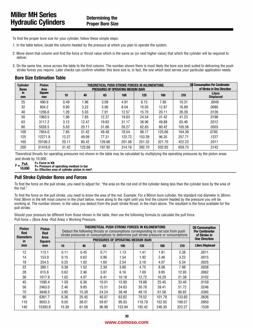
THEORETICAL PUSH STROKE FORCES IN KILONEWTONSDeduct the following thrusts or consumptions corresponding to rod size from push
stroke pressures or consumptions to determine pull stroke pressure or consumptionsPRESSURES OF OPERATING MEDIUM (BAR)
10 40 63 100 125 160 210 Liters Displaced
12 113.1 0.11 0.45 0.71 1.13 1.41 1.81 2.38 .001114 153.9 0.15 0.62 0.96 1.54 1.92 2.46 3.23 .001518 254.5 0.25 1.02 1.60 2.54 3.18 4.07 5.34 .002522 380.1 0.38 1.52 2.39 3.80 4.75 6.08 7.98 .003828 615.8 0.62 2.46 3.87 6.16 7.69 9.85 12.93 .006236 1017.9 1.02 4.07 6.41 10.18 12.72 16.29 21.38 .010245 1590.4 1.59 6.36 10.01 15.90 19.88 25.45 33.40 .015956 2463.0 2.46 9.85 15.51 24.63 30.78 39.41 51.72 .024670 3848.5 3.85 15.39 24.24 38.48 48.10 61.58 80.82 .038590 6361.7 6.36 25.45 40.07 63.62 79.52 101.79 133.60 .0636110 9503.3 9.50 38.01 59.87 95.03 118.79 152.05 199.57 .0950140 15393.8 15.39 61.58 96.98 153.94 192.42 246.30 323.27 .1539
Cylinder Piston THEORETICAL PUSH STROKE FORCES IN KILONEWTONS Oil Consumption Per CentimeterBores Area PRESSURES OF OPERATING MEDIUM (BAR) of Stroke in One Direction
in Square10 40 63 100 125 160 210mm mm
25 490.9 0.49 1.96 3.09 4.91 6.13 7.85 10.31 .004932 804.2 0.80 3.22 5.06 8.04 10.05 12.87 16.89 .008040 1256.6 1.26 5.03 7.91 12.57 15.70 20.11 26.39 .012650 1963.5 1.96 7.85 12.37 19.63 24.54 31.42 41.23 .019663 3117.2 3.12 12.47 19.63 31.17 38.96 49.88 65.46 .031280 5026.5 5.03 20.11 31.66 50.27 62.83 80.42 105.56 .0503100 7854.0 7.85 31.42 49.48 78.54 98.17 125.66 164.39 .0785125 12271.8 12.27 49.09 77.31 122.72 153.39 96.35 257.71 .1227160 20106.2 20.11 80.42 126.66 201.06 251.32 321.70 422.23 .2011200 31416.0 31.42 125.66 197.92 314.16 392.70 502.65 659.73 .3142
Miller MH SeriesHydraulic Cylinders
Determining theProper Bore Size
30
Bore Size Estimation Table
To find the proper bore size for your cylinder, follow these simple steps:
1. In the table below, locate the column headed by the pressure at which you plan to operate the system.
2. Move down that column and find the force or thrust value which is the same as (or next higher value) that which the cylinder will be required to deliver.
3. On the same line, move across the table to the first column. The number shown there is most likely the bore size best suited to delivering the push stroke forces you require. Later checks can confirm whether this bore size is, in fact, the one which best serves your particular application needs.
Theoretical thrusts for operating pressures not shown in the table may be calculated by multiplying the operating pressures by the piston areasand divide by 10,000.
F = PxA10,000
To find the force on the pull stroke, you need to adjust for: “the area on the rod end of the cylinder being less than the cylinder bore by the area ofthe rod.”
To find the force on the pull stroke, you need to know the area of the rod. Example: For a 80mm bore cylinder, the standard rod diameter is 36mm.Find 36mm in the left most column in the chart below, move along to the right until you find the column headed by the pressure you will beworking at. The number shown, is the value you deduct from the push stroke thrust, in the chart above. The resultant is the force available for thepull stroke.
Should your pressure be different from those shown in the table, then use the following formula to calculate the pull force.Pull force = (Bore Area -Rod Area) x Working Pressure.
PistonRod
Diametersin
mm
PistonRodArea
Squaremm
Oil Consumption Per Centimeter
of Stroke in One Direction
Pull Stroke Cylinder Bores and Forces
LitersDisplaced
F= Force in KNP= Pressure of operating medium in barA= Effective area of cylinder piston in mm2.
www.comoso.com

Miller MH SeriesHydraulic Cylinders
Stop Tubes for LongPush Stroke Cylinders
The use of a stop tube is a generally accepted and preferred method forreducing piston and bearing loads on long push stroke cylinders and,additionally, for preventing jack-knifing or buckling of horizontallymounted, long stroke cylinders on push stroke. Stop tubes are moreeffective, less costly, and lighter in weight than oversize piston rods.
Positioned between the piston and cylinder head, a stop tube restrictsthe extended position of the rod so that the added distance between thepiston and bushing results in less strain, wear, and bearing load.
1. Examine the groups of cylinders illustrated on Page 32 and determine which, if any, of the mounting configurations corresponds to your
cylinder application and model number.
2. If your cylinder mounting style corresponds to any of those in Group A, then no stop tube is required. But, if cylinder operates on push stroke, an oversize rod may be required and you should check the following page. If your cylinder is like one of those in Group B, then a stop tube is recommended and you should proceed to Step 3.
Follow these simple steps to determine whether your cylinder requires a stop tube, and, if so, how long it should be.
NOTE:If your cylinder is similar to one of the Group C illustrations, then youshould calculate the turning moments and loads between piston and rodbushing to insure that they do not exceed 13.7 bar. Weight of fluid mustbe included on large dia. or long stroke cylinders. For assistance on this,contact Miller Fluid Power Application Engineering Dept. Next, continueon to Step 3, on the folowing page, to determine the length of stop tubeneeded.
Determining the Length and Need For Stop Tube
Stop TubeLength
Stop Tube
31
www.comoso.com
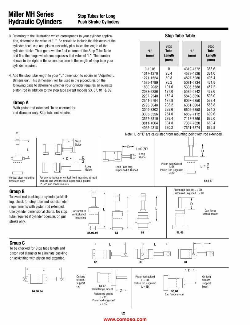
LL L
D
D
L
L LL
D
D2
L
L
L=0.7D
L
D
DD
=
D2L =
3. Referring to the illustration which corresponds to your cylinder applica-tion, determine the value of “L”. Be certain to include the thickness of thecylinder head, cap and piston assembly plus twice the length of thecylinder stroke. Then go down the first column of the Stop Tube Tableand find the range which encompasses that value of “L”. The numbershown to the right in the second column is the length of stop tube yourcylinder requires.
4. Add the stop tube length to your “L” dimension to obtain an “Adjusted L Dimension”. This dimension will be used in the procedures on the following page to determine whether your cylinder requires an oversize piston rod in addition to the stop tube except models 53, 67, 81, & 89.
Group AWith piston rod extended. To be checked forrod diameter only. Stop tube not required.
Group BTo avoid rod buckling or cylinder jackknif-ing, check for stop tube and rod diameterrequirements with piston rod extended.Use cylinder dimensional charts. No stoptube required if cylinder operates on pullstroke only.
Group CTo be checked for Stop tube length andpiston rod diameter to eliminate bucklingor jackknifing with piston rod extended.
“L”(mm)
0-10161017-12701271-15241525-17991800-20322033-22862287-25402541-27942795-30483049-33023303-35563557-38103811-40644065-4318
“L”(mm)
4319-45724573-48264827-50805081-53345335-55885589-58425843-60966097-63506351-66046605-68586859-71127113-73667367-76207621-7874
StopTube
Length(mm)
025.450.876.2101.6127.0152.4177.8203.2228.6254.0279.4304.8330.2
StopTube
Length(mm)
355.6381.0406.4431.8457.2482.6508.0533.4558.8584.2609.6635.0660.4685.8
Stop Tube Table
Vertical pivot mountingHead end only
ShortGuide
For any horizontal or vertical fixed mounting at headand cap end with the load supported & guided 51, 72, and mixed mounts
Load Pivot Mtg.Supported & Guided
LongGuide
LongGuide
Note: ‘L’ or ‘D’ are calculated from mounting point with rod extended.
53 & 67
81
Horizontal orvertical pivot
mounting
Piston rod guided: L = 2DPiston rod unguided L = 4D
Cap flangevertical mount
52, 68898284, 90, 94
On longstrokessupportcap 53, 67
Head flange mount52, 68
Cap flange mount
On longstrokessupporthead
Piston rod guidedL = 2D
Piston rod unguidedL = 4D
8982 81
84, 90, 94
Piston Rod GuidedL=D
Piston Rod unguidedL=2D
Miller MH SeriesHydraulic Cylinders
Stop Tubes for LongPush Stroke Cylinders
Piston rod guidedL = 2D
Piston rod unguidedL = 4D
32
www.comoso.com
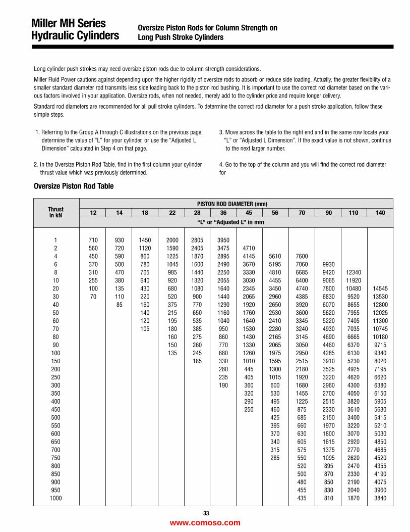
Miller MH SeriesHydraulic Cylinders
Oversize Piston Rods for Column Strength onLong Push Stroke Cylinders
Long cylinder push strokes may need oversize piston rods due to column strength considerations.
Miller Fluid Power cautions against depending upon the higher rigidity of oversize rods to absorb or reduce side loading. Actually, the greater flexibility of asmaller standard diameter rod transmits less side loading back to the piston rod bushing. It is important to use the correct rod diameter based on the vari-ous factors involved in your application. Oversize rods, when not needed, merely add to the cylinder price and require longer delivery.
Standard rod diameters are recommended for all pull stroke cylinders. To determine the correct rod diameter for a push stroke application, follow thesesimple steps.
1. Referring to the Group A through C illustrations on the previous page, determine the value of “L” for your cylinder, or use the “Adjusted LDimension” calculated in Step 4 on that page.
2. In the Oversize Piston Rod Table, find in the first column your cylinder thrust value which was previously determined.
3. Move across the table to the right end and in the same row locate your “L” or “Adjusted L Dimension”. If the exact value is not shown, continueto the next larger number.
4. Go to the top of the column and you will find the correct rod diameterfor
Oversize Piston Rod Table
ThrustPISTON ROD DIAMETER (mm)
in kN 12 14 18 22 28 36 45 56 70 90 110 140
“L” or “Adjusted L” in mm
1 710 930 1450 2000 2805 39502 560 720 1120 1590 2405 3475 47104 450 590 860 1225 1870 2895 4145 5610 76006 370 500 780 1045 1600 2490 3670 5195 7060 99308 310 470 705 985 1440 2250 3330 4810 6685 9420 1234010 255 380 640 920 1320 2055 3030 4455 6400 9065 1192020 100 135 430 680 1080 1640 2345 3450 4740 7800 10480 1454530 70 110 220 520 900 1440 2065 2960 4385 6830 9520 1353040 85 160 375 770 1290 1920 2650 3920 6070 8655 1280050 140 215 650 1160 1760 2530 3600 5620 7955 1202560 120 195 535 1040 1640 2410 3345 5220 7405 1130070 105 180 385 950 1530 2280 3240 4930 7035 1074580 160 275 860 1430 2165 3145 4690 6665 1018090 150 260 770 1330 2065 3050 4460 6370 9715100 135 245 680 1260 1975 2950 4285 6130 9340150 185 330 1010 1595 2515 3910 5230 8020200 280 445 1300 2180 3525 4925 7195250 235 405 1015 1920 3220 4620 6620300 190 360 600 1680 2960 4300 6380350 320 530 1455 2700 4050 6150400 290 495 1225 2515 3820 5905450 250 460 875 2330 3610 5630500 425 685 2150 3400 5415550 395 660 1970 3220 5210600 370 630 1800 3070 5030650 340 605 1615 2920 4850700 315 575 1375 2770 4685750 285 550 1095 2620 4520800 520 895 2470 4355850 500 870 2330 4190900 480 850 2190 4075950 455 830 2040 39601000 435 810 1870 3840
33
www.comoso.com
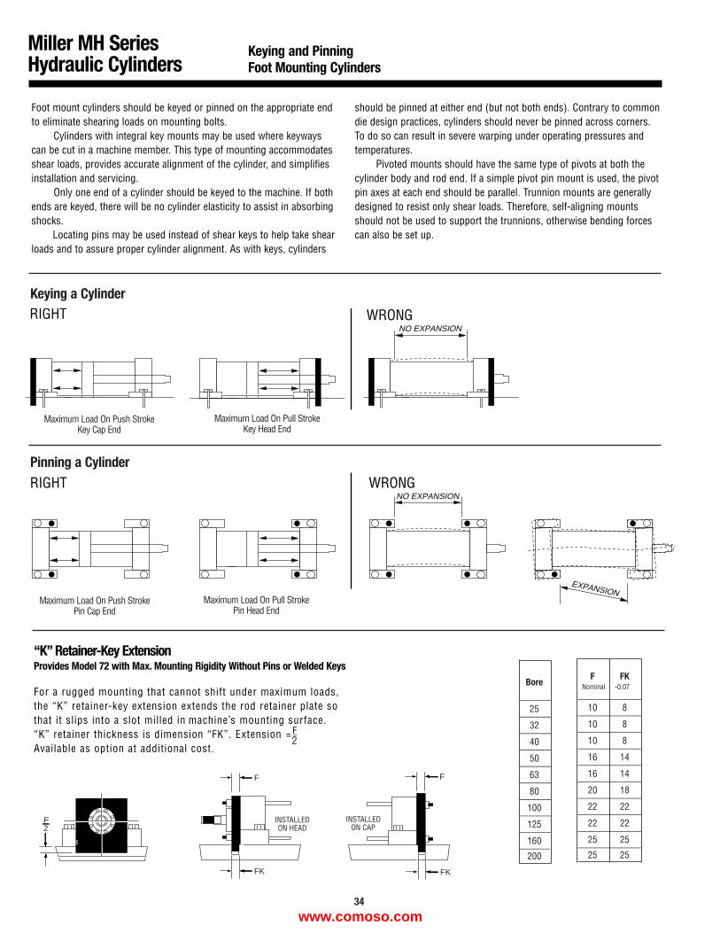
For a rugged mounting that cannot shift under maximum loads,the “K” retainer-key extension extends the rod retainer plate sothat it slips into a slot milled in machine’s mounting surface.“K” retainer thickness is dimension “FK”. Extension = F
Available as option at additional cost.
F
FK
F
FK
F2
Miller MH SeriesHydraulic Cylinders
Keying and PinningFoot Mounting Cylinders
Foot mount cylinders should be keyed or pinned on the appropriate endto eliminate shearing loads on mounting bolts.
Cylinders with integral key mounts may be used where keywayscan be cut in a machine member. This type of mounting accommodatesshear loads, provides accurate alignment of the cylinder, and simplifiesinstallation and servicing.
Only one end of a cylinder should be keyed to the machine. If bothends are keyed, there will be no cylinder elasticity to assist in absorbingshocks.
Locating pins may be used instead of shear keys to help take shearloads and to assure proper cylinder alignment. As with keys, cylinders
should be pinned at either end (but not both ends). Contrary to commondie design practices, cylinders should never be pinned across corners.To do so can result in severe warping under operating pressures andtemperatures.
Pivoted mounts should have the same type of pivots at both thecylinder body and rod end. If a simple pivot pin mount is used, the pivotpin axes at each end should be parallel. Trunnion mounts are generallydesigned to resist only shear loads. Therefore, self-aligning mountsshould not be used to support the trunnions, otherwise bending forcescan also be set up.
“K” Retainer-Key ExtensionProvides Model 72 with Max. Mounting Rigidity Without Pins or Welded Keys
NO EXPANSION
RIGHT WRONG
NO EXPANSION
EXPANSION
RIGHT WRONG
Keying a Cylinder
Pinning a Cylinder
INSTALLEDON HEAD
INSTALLEDON CAP
Maximum Load On Push StrokeKey Cap End
Maximum Load On Pull StrokeKey Head End
Maximum Load On Push StrokePin Cap End
Maximum Load On Pull StrokePin Head End
_____________
_____________
_____________
_____________
_____________
_____________
_____________
_____________
_____________
_____________
F FK
10 8
10 8
10 8
16 14
16 14
20 18
22 22
22 22
25 25
25 25
______
______
______
______
______
______
______
______
______
______
Bore
25
32
40
50
63
80
100
125
160
200
Nominal -0.07
34
2
www.comoso.com
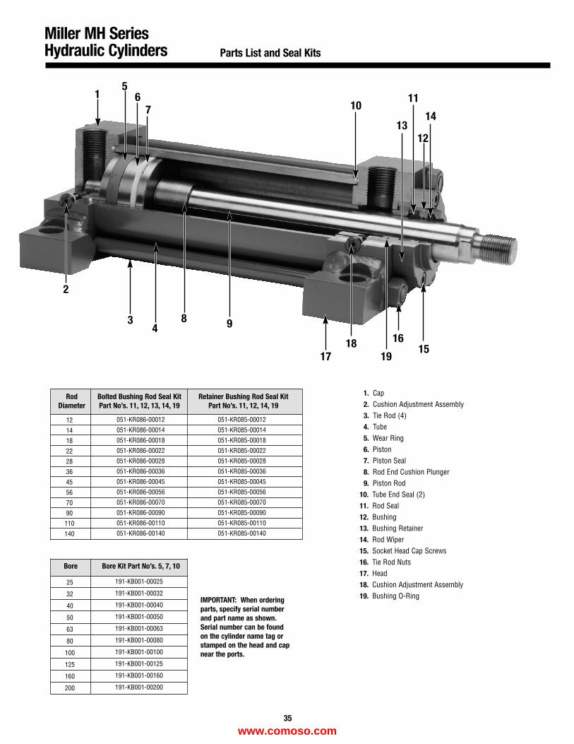
Miller MH SeriesHydraulic Cylinders Parts List and Seal Kits
RodDiameter
Bolted Bushing Rod Seal KitPart No’s. 11, 12, 13, 14, 19
Retainer Bushing Rod Seal Kit Part No’s. 11, 12, 14, 19
12
14
18
22
28
36
45
56
70
90
110
140
Bore Bore Kit Part No’s. 5, 7, 10
25
32
40
50
63
80
100
125
160
200
IMPORTANT: When orderingparts, specify serial numberand part name as shown.Serial number can be foundon the cylinder name tag orstamped on the head and capnear the ports.
1. Cap2. Cushion Adjustment Assembly3. Tie Rod (4)4. Tube5. Wear Ring6. Piston7. Piston Seal8. Rod End Cushion Plunger9. Piston Rod
10. Tube End Seal (2)11. Rod Seal 12. Bushing13. Bushing Retainer14. Rod Wiper15. Socket Head Cap Screws16. Tie Rod Nuts17. Head18. Cushion Adjustment Assembly19. Bushing O-Ring
051-KR086-00012 051-KR085-00012
051-KR086-00014 051-KR085-00014
051-KR086-00018 051-KR085-00018
051-KR086-00022 051-KR085-00022
051-KR086-00028 051-KR085-00028
051-KR086-00036 051-KR085-00036
051-KR086-00045 051-KR085-00045
051-KR086-00056 051-KR085-00056
051-KR086-00070 051-KR085-00070
051-KR086-00090 051-KR085-00090
051-KR086-00110 051-KR085-00110
051-KR086-00140 051-KR085-00140
191-KB001-00025
191-KB001-00032
191-KB001-00040
191-KB001-00050
191-KB001-00063
191-KB001-00080
191-KB001-00100
191-KB001-00125
191-KB001-00160
191-KB001-00200
1
2
34
8 9
1011
12
14
1817 19
1615
13
56
7
35
www.comoso.com
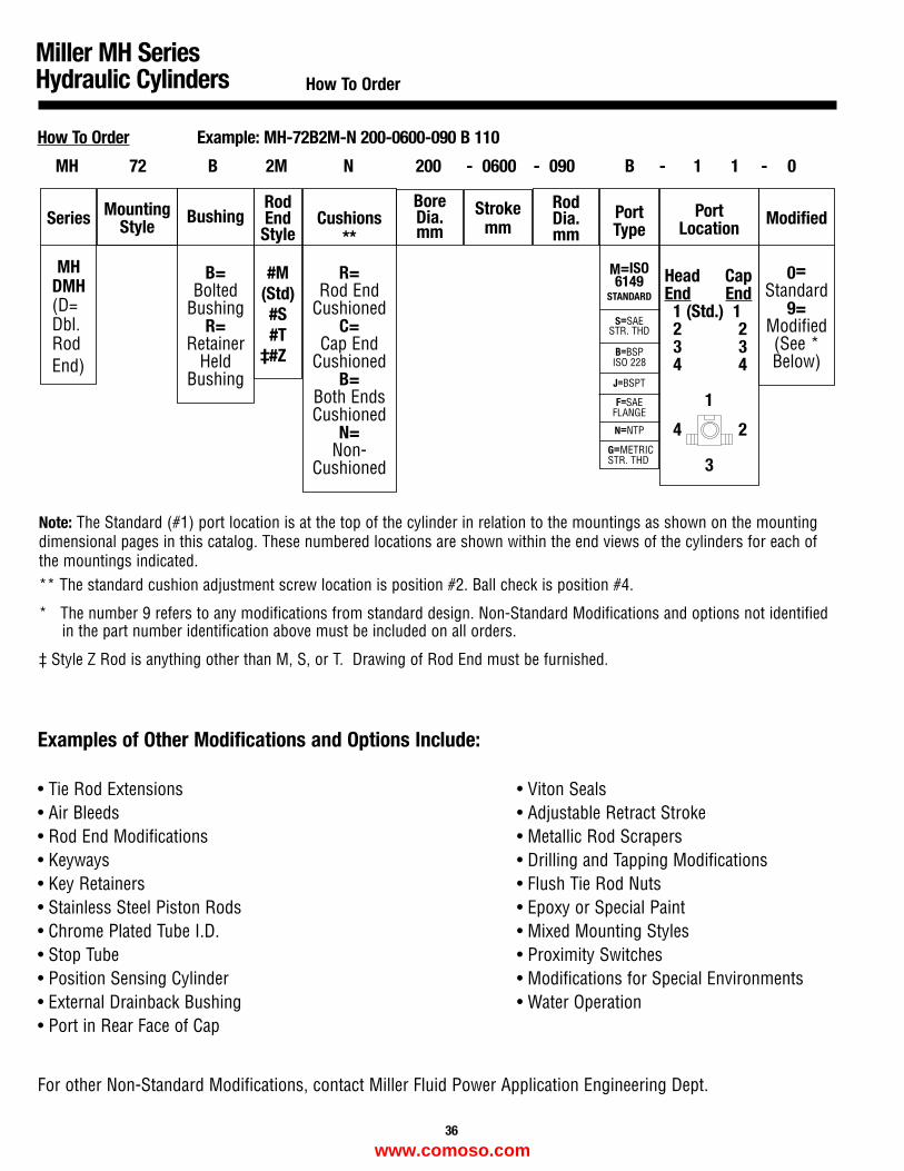
How To Order Example: MH-72B2M-N 200-0600-090 B 110
Series
MHDMH(D=Dbl.RodEnd)
Bushing
B=Bolted
BushingR=
RetainerHeld
Bushing
RodEnd
Style
#M(Std)#S#T
‡#Z
Cushions**
R=Rod End
CushionedC=
Cap EndCushioned
B=Both EndsCushioned
N=Non-
Cushioned
BoreDia.mm
Strokemm
RodDia.mm
PortType
M=ISO6149
STANDARD
S=SAESTR. THD
B=BSPISO 228
J=BSPT
F=SAEFLANGE
N=NTP
PortLocation
Head CapEnd End
1 (Std.) 12 23 34 4
1
4 2
3
Modified
0=Standard
9=Modified(See *Below)
MountingStyle
MH 72 B 2M N 200 - 0600 - 090 B - 1 1 - 0
Note: The Standard (#1) port location is at the top of the cylinder in relation to the mountings as shown on the mountingdimensional pages in this catalog. These numbered locations are shown within the end views of the cylinders for each ofthe mountings indicated.** The standard cushion adjustment screw location is position #2. Ball check is position #4.
* The number 9 refers to any modifications from standard design. Non-Standard Modifications and options not identifiedin the part number identification above must be included on all orders.
‡ Style Z Rod is anything other than M, S, or T. Drawing of Rod End must be furnished.
Miller MH SeriesHydraulic Cylinders How To Order
Examples of Other Modifications and Options Include:
• Tie Rod Extensions • Viton Seals• Air Bleeds • Adjustable Retract Stroke• Rod End Modifications • Metallic Rod Scrapers• Keyways • Drilling and Tapping Modifications• Key Retainers • Flush Tie Rod Nuts• Stainless Steel Piston Rods • Epoxy or Special Paint• Chrome Plated Tube I.D. • Mixed Mounting Styles• Stop Tube • Proximity Switches• Position Sensing Cylinder • Modifications for Special Environments• External Drainback Bushing • Water Operation• Port in Rear Face of Cap
For other Non-Standard Modifications, contact Miller Fluid Power Application Engineering Dept.
36
G=METRICSTR. THD
www.comoso.com
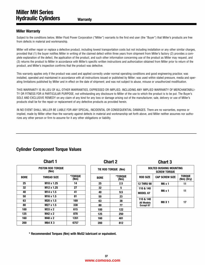
Miller MH SeriesHydraulic Cylinders Warranty
37
Miller Warranty
Subject to the conditions below, Miller Fluid Power Corporation (“Miller”) warrants to the first end user (the “Buyer”) that Miller’s products are freefrom defects in material and workmanship.
Miller will either repair or replace a defective product, including lowest transportation costs but not including installation or any other similar charges,provided that (1) the buyer notifies Miller in writing of the claimed defect within three years from shipment from Miller’s factory (2) provides a com-plete explanation of the defect, the application of the product, and such other information concerning use of the product as Miller may request, and(3) returns the product to Miller in accordance with Miller’s specific written instructions and authorization obtained from Miller prior to return of theproduct, and Miller’s inspection confirms that the product was defective.
This warranty applies only if the product was used and applied correctly under normal operating conditions and good engineering practice; wasinstalled, operated and maintained in accordance with all instructions issued or published by Miller; was used within stated pressure, media and oper-ating limitations published by Miller and in effect on the date of shipment; and was not subject to abuse, misuse or unauthorized modification.
THIS WARRANTY IS IN LIEU OF ALL OTHER WARRANTIES, EXPRESSED OR IMPLIED, INCLUDING ANY IMPLIED WARRANTY OF MERCHANTABILI-TY OR FITNESS FOR A PARTICULAR PURPOSE, not withstanding any disclosure to Miller of the use to which the product is to be put. The Buyer’sSOLE AND EXCLUSIVE REMEDY on any claim of any kind for any loss or damage arising out of the manufacturer, sale, delivery or use of Miller’sproducts shall be for the repair or replacement of any defective products as provided herein.
IN NO EVENT SHALL MILLER BE LIABLE FOR ANY SPECIAL, INCIDENTAL OR CONSEQUENTIAL DAMAGES. There are no warranties, express orimplied, made by Miller other than the warranty against defects in material and workmanship set forth above, and Miller neither assumes nor autho-rizes any other person or firm to assume for it any other obligations or liability.
PISTON ROD TORQUE(Nm)
BORE THREAD SIZE *TORQUE(Nm)
25 M10 x 1.25 1432 M12 x 1.25 2740 M14 x 1.5 4150 M16 x 1.5 8163 M20 x 1.5 16980 M27 x 1.5 338
100 M33 x 2 615125 M42 x 2 878160 M48 x 2 1351
200 M64 X 3 6757
TIE ROD TORQUE (Nm)
BORE *TORQUE(Nm)
25 2.532 540 9.550 2363 3880 77
100 122125 250160 481
200 812
BOLTED BUSHING MOUNTINGSCREW TORQUE
ROD SIZE CAP SCREW SIZE TORQUE(Nm) (Dry)
12 THRU 90 M6 x 1 11
110 & 140M6 x 1 11
MODEL 67
110 & 140M8 X 1 17
Cylinder Component Torque Values
Chart 1 Chart 2 Chart 3
* Recommended Torques (Nm) with MoS2 lubricant or equivalent.
All ModelsExcept 67
www.comoso.com
Miller Fluid PowerMain Plant800 North York RoadBensenville, IL 60106(630) 766-3400—Local(800) 323-2520—Elsewhere(630) 350-0294—FAX
Miller Fluid Power33067 Industrial RoadLivonia, MI 48150(800) 323-2520
Miller Fluid Power2050 Del RioOntario, CA 91761(800) 323-2520
Miller Fluid Power Canada Ltd.1214 KamatoMississauga, Ontario, Canada L4W 1Y1(800) 268-0205—Ontario & Quebec(905) 625-2780—Elsewhere(905) 625-8724—FAX
Miller Potencia Fluida, S.A. de C.V.Israel No. 301 Esq. Damasco Col. Ricardo B. Anaya 2A. SECCApartado Postal F-124178090 San Luis Potosi, S.L.P. Mexico(48) 21-19-21, 22, 37(48) 21-21-60—FAX
Miller Potencia Fluida, S.A. de C.V.Nogal No. 45—Despacho 202 Col. Sant Maria La RiberaDelegacion: CuauhtemocMexico, D.F. 06400(5) 547-2474(5) 541-1123—FAX
Miller Fluid Power (UK) Ltd.Unit 3, Bailey DriveNorwood Industrial EstateKillamarsh, SheffieldSouth Yorkshire, England S31 8HB(441)-462-438303(441)-462-420901—FAX
All specifications and information subject tochange without notice or prior obligation.
File 9787 089909
www.comoso.com