i investigating the effect of magnetic force on …umpir.ump.edu.my/5185/1/cd6372.pdf · zarah...
TRANSCRIPT

i
INVESTIGATING THE EFFECT OF MAGNETIC FORCE ON THE FLOW
BEHAVIOR OF PIPELINE
GEETHA D/O RAMANATHAN
A thesis submitted in fulfilment of the requirement for the award of the Degree of
Bachelor of Chemical Engineering (Gas Technology)
Faculty of Chemical & Natural Resources Engineering
UNIVERSITI MALAYSIA PAHANG
JANUARY 2012
vi
ABSTRACT
Drag forces has been the main problem that occurs in pipeline and loss energy due to
the water transmission along the pipeline. During the transmission of water in the
pipeline, it needs high consumption of pumping power in the pipeline due to the fluids
are flow in order of turbulent flow by against the fluid friction, which has been
happened in the pipeline wall and results in drag forces of the pipeline. Consequently,
the drag forces in the pipeline can be reduced by addition of drag reducing agent to
improvise the fluid transmission in pipeline. The purpose of this research work is to
study the effect of particle size and concentrations of suspended solid such as iron
powder applied to magnetic force flow and ultimately investigate the flow behaviour in
multi phase flow in the pipeline. In this study, the investigation is based on the role of
ferromagnetic powder such as iron powder used as drag reduction agent to reduce the
drag forces and less turbulent in the fluid transmission pipeline. In the experimental
work, check the flow behaviour of pipeline when the iron powders add to the fluid
transmissions with concentration of 100ppm, 300ppm and 500ppm and provided with
and without magnetic force. Moreover, portable magnetic device has been used to apply
magnetic force to the flow in the pipeline. The experimental procedures carried out in
an experimental rig and obtain the pressure drop readings for drag reduction calculation.
Iron powder particles are suitable and best method for drag reducing agent. In addition,
smaller particle size at high concentration able to show the higher drag reduction
compared to bigger particle size. The turbulence flow of the pipeline can be reduced by
appliance of magnetic field and the high power of magnetic force able to reduce the
drag reduction at higher Reynolds number. The average value of drag reduction for the
pipe length of 1.5m was recorded for iron powder of particle size of 60µm is 25% and
particle size of 120µm was achieved about 10% for concentration of 300ppm with the
magnetic power of 720W.

vii
ABSTRAK
Daya seretan merupakan masalah utama yang berlaku semasa pengaliran air sepanjang
saluran paip yang boleh menyebabkan kehilangan tenaga dalam saluran paip. Semasa
pengaliran air dalam saluran paip, ia memerlukan penggunaan pam yang berkuasa tinggi
dan menyebabkan aliran gelora terhadap geseran bendalir, yang telah berlaku di antara
dinding saluran paip dan daya seretan. Oleh itu, daya seretan boleh mengurangkan
seretan dengan mengunakan ejen daya penguranga untuk menambah baik pengaliran
bendalir dalam saluran paip. Tujuan kerja penyelidikan ini dijalankan untuk mengkaji
kesan saiz zarah dan kepekatan pepejal terampai sebagai contoh serbuk besi yang
digunakan untuk menambah baikan saluran paip dengan menguji aliran daya magnet
pada saluran paip. Dalam kajian ini, siasatan berdasarkan peranan serbuk feromagnet
seperti serbuk besi yang digunakan sebagai agen pengurangan seretan untuk
mengurangkan daya seret dan aliran gelora di dalam saluran paip untuk mengalirkan
bendalir. Dalam kerja uji kaji, memeriksa terhadap pengaliran saluran paip apabila
menambah serbuk besi semasa pengaliran bendalir dengan kepekatan 100ppm, 300ppm
dan 500ppm dan mengalir dengan daya magnet. Selain itu, magnet mudah alih telah
digunakan untuk memeriksa kuasa magnet terhadap saluran paip. Prosedur uji kaji telah
dijalankan dengan menggunakan rig uji kaji dan mendapatkan bacaan perubahan
terhadap tekanan untuk pengiraan pengurangan daya seret. Zarah serbuk besi adalah
kaedah yang sesuai dan terbaik untuk menjadikan sebagai ejen pengurangan daya
seretan. Di samping itu, saiz zarah yang lebih kecil dengan kepekatan yang tinggi
mampu mengurangkan daya seretan yang lebih tinggi berbanding dengan saiz zarah
yang lebih besar. Aliran gelora dalam saluran paip boleh dikurangkan dengan
mengaplikasikan medan magnet dan juga mengurangkan pengurangan daya seret
dengan kuasa tenaga magnet yang tinggi pada nombor Reynolds yang lebih tinggi. Nilai
peratus pengurangan daya seret pada paip 1.5m telah dicatatkan bagi serbuk besi yang
bersaiz zarah 60μm dengan pencapaian 25% dan saiz zarah 120μm telah mencapai kira-
kira 10% bagi kepekatan 300ppm pada kuasa magnet 720W.

viii
TABLE OF CONTENTS
Page
SUPERVISOR’S DECLARATION ii
STUDENTS DECLARATION iii
DEDICATION iv
ACKNOWLEDGEMENTS v
ABSTRACT vi
ABSTRAK vii
TABLE OF CONTENTS viii
LIST OF TABLES x
LIST OF FIGURES xi
LIST OF SYMBOLS xii
LIST OF ABBREVATIONS xiii
CHAPTER 1 INTRODUCTION
1.1 Introduction 1
1.2 Background of the Study 1
1.3 Problem Statement 2
1.4 Objectives of the Research 4
1.5 Scope of Research 4
1.6 Significance of the Study 4
CHAPTER 2 LITERATURE REVIEW
2.1 Introduction 6
2.2 Type of Flow in the Pipeline 6
2.2.1 Turbulent Flow in Pipeline 8
2.2.2 Eddies 9
2.2.3 Drag force in Pipeline Flow 10
2.3 Drag Reduction 11
2.3.1 Drag Reduction Agent 12
2.4 Magnetic Field 17
2.4.1 Type of Metal to Attract the Magnetic Field 18
ix
2.4.2 Electromagnetic Induction Method 19
2.5 Conclusion 21
CHAPTER 3 METHODOLOGY
3.1 Introduction 22
3.2 Material 22
3.2.1 Suspended Solids 22
3.2.2 Medium of Fluid 23
3.3 Experimental 23
3.3.1 Flow Loop 24
3.3.2 Water Flow Meter 24
3.3.3 Magnetic Device 24
3.34 Rig of Fluid Friction 25
3.4 Experimental Procedure 26
CHAPTER 4 RESULTS AND DISCUSSIONS
4.1 Effect of Suspended Metals in Flow Behaviour 28
4.2 Effect of Magnetic Field to Iron Particles 29
4.3 Effect of Particle Size Iron Powder 33
CHAPTER 5 CONCLUSION AND RECOMMENDATIONS
5.1 Conclusions 35
5.2 Recommendations for the Future Research 36
REFERENCES 38
APPENDICES 42

x
LIST OF TABLES
Table No. Title Page
3.1 Properties of Iron Metal Powder 23
3.2 Properties of Water 23

xi
LIST OF FIGURES
Figure No. Title Page
2.1 Turbulent flow 8
2.2 Characteristics of flow 11
2.3 Attraction of magnet at the poles 18
3.1 Water flow meter 24
3.2 Magnet device 25
3.3 The magnet being fixed to the pipe together with its switch
box and connection box 25
3.4 Schematic diagram of experimental rig 26
4.1 Pressure drop influenced by the magnetic field applied at the
particle size of 60µm for the concentration of 300ppm at
Re=78 226.50 29
4.2 Relationship between Reynolds number and percentage of
drag reduction with different iron particle concentration of
300ppm for size 60μm at power setting 720W 30
4.3 Relationship between Reynolds number and percentage of
drag reduction with different iron particle concentration of
300ppm for size 120μm at power setting 720W 31
4.4 Relationship between Reynolds number and percentage of
drag reduction with different iron particle concentration of
300ppm for size 60μm compared to flow of suspended
iron particles and flow of suspended iron particles with
power of 240W, 480W and 720W 32
4.5 Relationship between Reynolds number and percentage of
drag reduction with different iron particle concentration of
300ppm for size of 120μm compared to flow of suspended
iron particles and flow of suspended iron particles with
power of 240W, 480W and 720W 33
4.6 Relationship between Reynolds number and percentage of
drag reduction with different iron particle concentration of
300ppm compared between iron particle size of 60μm
and 120μm at power setting of 720W 34

xii
LIST OF SYMBOLS
% Percentage
°C Degree celsius
min Minute
ppm Parts per million
µm Micrometer
Re Reynolds number
g Gram
cm
Centimeter
W Waat
Kg Kilogram
m Metre
s Second
ρ Density of water
V Velocity of water
d Diameter of pipe
µ Viscosity of water
Q Flow rates of water
Dr % Drag reduction percentage

xiii
LIST OF ABBREVIATIONS
CTAC CetylTrimethyl Ammonium Chloride
NaSal Sodium Salicylate
MRI Magnetic resonance imaging
PIV Particle image velocimetry
AC Alternative Current
P Pump
T Tank
PT Pressure Transmitter
MV Valve
PVC Polyvinyl Chloride

1
CHAPTER 1
INTRODUCTION
1.1 INTRODUCTION
In an introduction part, explains on the background of study of the drag
reduction that occurs in the pipeline, continue with the problem statement, objective of
the project, scope of study and rational and significance to improvise the turbulent flow.
1.2 BACKGROUND OF STUDY
Liquids and gases form known as a real or an ideal fluid. However, an ideal fluid
contains property of incompressible and frictionless but a real fluid has viscosity and
compressible property. There have two types of flow such as laminar and turbulent
flow. Laminar and turbulent can occur in the pipeline. The first person distinguish the
differences between the flows through experimentally is Osborne Reynolds (1842 –
1912) by using reynolds number.
The laminar flow will occur when the reynolds number is less than 2000. If the
reynolds number is greater than 4000, the flow in pipe is known as turbulent flow. The
two limits in between of reynolds number of 2300 until 4000 are called as transitional
flow (Munson et al, 2006). Turbulent flow occurs when there is friction between the
flow of fluids and wall of the pipe. The eddying motions which are varies with different
size of motion in turbulent flow of pipeline and the large equipment part from
mechanical energy in the pipeline flow goes into the formation of these eddies which
eventually dissipate the energy as heat (Warhaft, 1997). The turbulent flow is affected
from the roughness of surface. When increase the surface roughness it increases the
drag in the pipeline.

2
Drag was the main reason for the loss of energy in pipeline for the transportation
purpose. These energy losses are can be identified through the pressure drop, which will
results in consuming high pumping power. Therefore, to reduce the drag should use the
drag reduction effect in the turbulent pipeline flows, which was discovered by Toms.
This phenomenon was known as Tom’s phenomenon (Toms, 1948).
The main purpose of drag reduction is to delay the onset of turbulent flows and
reducing the flow resistance especially in the pipelines, in order to improve the flow of
fluid-mechanical efficiency in pipeline. Otherwise, the drag reducer will shift the
transition from a laminar flow to a turbulent with higher flow velocity (Truong, 2001).
Recebli and Kurt (2008) demonstrated that increasing the magnetic field intensity
causes the local velocity of a two-phase steady flow along a horizontal glass pipe to
decrease.
In addition, the turbulent friction factor can reduce by supplying electricity with
magnetic force in pipeline. A charged particle passing in the presence of a current was
experience a force from the current is called as magnetic force. This type of force is
known as electromagnetic force. Moreover, the magnetic force can be expressed in
terms of the magnetic vector or the magnetic field discussed in the electric induction
force. Both the particles velocity and the magnetic field were perpendicular in the form
of magnetic force.
1.3 PROBLEM STATEMENT
Drag reduction is not only applied in a chemical industries but also highly
demand in an oil and gas refinery industries, medical, mining, marine, bio medical
applications and jet cutting for fluid transportation in pipeline for the reason that
moving fluid, energy will dissipated due to the drag friction. Widely used in most
industries due to the purpose of drag reduction in order to reduce the energy loss in
pipeline. Basically, in industry cost saving is the most high concern on limitation on
power consumption. Reduce the turbulence flow in pipelines in order to power
consumption saving and improve the flow. Instead that, water was supply into the
pipeline with high flow rate but finally the water flow rate was become low due to the

3
turbulent flow that occurs along the pipeline. Therefore, to increase the flows in pipeline
by consume loads of power for the purpose of transportation in channel. Ultimately, the
costs also will increase drastically.
Initially, the drag reductions in the pipeline have been studied, by addition of
polymers, fibers or surfactant in order to reduce the drag reduction in a pipeline. Lately,
the most comment material that used as drag reduction agent in the pipeline were
polymers. However, the polymers have the characteristics as stretched along the axis
and the elasticity supply the energy to reduce the drag in the pipeline but a fully
prolonged chain of polymer cause a poor resisting degradation caused by the pumping
shear power and degrade thermally at high temperature. Therefore, polymers were
loosed their drag reducing ability permanently. Polymer as a drag reduction agent was
able to cause a problem to the environment due to the toxic or environmental pollutant.
Polymer also used at low concentration to avoid the toxicity.
Therefore, in this current study metal solid particle suspension used as drag
reduction agent such as apply the magnetic force towards the pipeline was investigated
by using an experimental approach.
4
1.4 OBJECTIVE
The aim of this investigation was studied to achieve this objective:
• To study the water flow behavior in pipeline with influence of suspended
solid that can attract to the magnetic force.
• To study the effect of size and concentration of suspended solid in the
magnetic force on the flow behavior in multi phase flow in the pipeline.
• To study the mechanism that controls the drag reduction experimental work
for the pipeline.
1.5 SCOPE OF STUDY
Scope of this study was to achieve the objectives to study the effect of magnet
device to the influences of the iron powder in the magnetic force and identifies the
behaviour of the turbulent flow in the pipeline. The iron solid powders that tested are
micron size particles with the size of 60 µm and 120 µm. Magnetic fields were applied
using a custom made magnet device to study the influence of iron particles under the
action of magnetic field on the turbulent flow of the pipeline. In this study water was
used as transporting medium. At last, collect the pressure readings, calculate the
pressure drop, followed by the percentage of the drag reduction, and finally calculate the
Reynolds number and velocity by using the volumetric flow rate so that to make sure
the flows are less turbulent in the pipeline.
1.6 RATIONAL AND SIGNIFICANCE
There have many benefit use of drag reduction. The significance of this study
was to discover a new method to reduce the drag forces in the pipeline, in order to
saving the pumping power consumption. Drag reduction able to enhance the flow rate of
water in the pipeline by using the magnetic force as a flow improver. The presence of
turbulence flow can be reduced under the influenced of magnetic field by adding the
suspended metal solid particles towards the pipeline. Last time, use additive agent such
as fiber, polymer and surfactant as a drag reduction agent has to reduce the drag force
but now can use magnetic force in pipeline to improve the flow behaviour of water. The

5
higher drag reduction performance of the metal obtains at the stronger magnetic field.
These drag reduction can overcome the energy loss in pipeline. Moreover, the use of
pump in plant will be reduced and the energy demanded for the pump is reduced too.
Automatically, it saves the cost.

6
CHAPTER 2
LITERATURE REVIEW
2.1 INTRODUCTION
In a literature review, the theoretical particulars that will be covered are type of
flow in pipeline, drag force in pipeline flow, turbulent flow in pipeline, and effect of
magnetic force on the flow behaviour of water in pipeline. Finally, in the literature
review discussed about the economical and commercial applications and benefits.
2.2 TYPE OF FLOW IN THE PIPELINE
In many fields, flow was distinguished by calculating Reynolds number. At low
number of Reynolds, the viscous force is larger compared than the inertia force. The
small changes in the disturbances in the velocity field, created perhaps by small
roughness elements on the surface, or pressure perturbations from external sources such
as vibrations in the surface or strong sound waves, damped out and not allowed to grow.
The case for pipe flow at Reynolds numbers less than the critical values of 2300, which
is based on pipe diameter and average velocity, and for boundary layers with a
Reynolds number less than about 200,000 were based on distance from the origin of the
layer and the free stream velocity (Warhaft, 1997).
The viscous damping action become less when the Reynolds number increases,
and at the some point it becomes possible for small perturbations to grow. The flow of
water can become unstable, and it can experience transition to a turbulent state where
large variations in the velocity field can be maintained. The disturbances are very small,
as in the case where the surface is very smooth, or if the wavelength of the disturbance

7
is not near the point of resonance, the transition to turbulence will occur at a higher
Reynolds number than the critical value. Therefore, the point of transition does not
correspond to a single Reynolds number, and it is possible to delay transition to
relatively large values by controlling the disturbance environment. At very high
Reynolds numbers, it is not possible to maintain laminar flow since under these
conditions even minute disturbances will be amplified into turbulence (Warhaft, 1997).
The Reynolds number, in the case of laminar flow in a straight pipe of the fluid
particles travel in a straight pipes the particles travel in straight lines without losing their
identify by mixing between layers. Thus, fluid particles between two adjacent layers do
not mix except by molecular diffusion. If any disturbance in the form of velocity; hence
the flow again comes back to laminar state. As the Reynolds number exceeds the limits
of approximately 2300, the laminar flow in a pipe may become, leading to turbulent
flow condition (Garde, R.J., 2000).
Moreover, it can be seen that the loss of pressure in a steady uniform laminar
flow in a pipe is directly proportional to the first power of velocity and viscosity, and
inversely proportional to square root of diameter. Laminar flow is between the parallel
plates and flow through porous materials. In other hand, the inertial effects are
neglected the pressure loss which is independent of the mass of density of the fluid.
Another characteristic is the extreme no uniformity in velocity distribution. This gives
an energy correction factor of two for pipe flow as against 1.05 to 1.10 for turbulent
flow where the velocity distribution follows logarithmic law (Garde, R.J., 2000).
Lastly, it will pointed out the drag force experienced by the deformation of fluid
is opposed by the viscous stresses that vary directly with the rate of deformation; there
is continuous expenditure of energy. Therefore, in a steady uniform flow, there is a
continuous transformation of mechanical energy into heat. The turbulent flow is formed
based of intense mixing; there is much greater expenditure of energy in turbulent flow
than in laminar flow (Garde, R.J., 2000).
8
2.2.1 Turbulent Flow in Pipeline
Thus, even in an otherwise steady turbulent flow the velocity at a given point
will randomly fluctuate with time, whereas even in uniform turbulent flow
instantaneous velocity at all time, whereas even in uniform turbulent flow instantaneous
velocity at all points along a streamline would vary randomly. The flow is varied from
parameters such as pressure, temperature, sediment concentration at flow point, or force
on structures such as smoke stacks and suspension bridges for turbulent flow. The
lateral movement of fluid particles in the case of laminar flow takes place due to
molecular diffusion and it is very small indeed. In turbulent flow, lumps of fluid
particles move laterally and longitudinally giving rise to the concept of eddy motion
(Garde, R.J., 2000).
The flow behavior in pipeline is turbulent will be occurred when the behavior of
flow contains the eddying motions of all the sizes, and the mechanical energy which is
contain of large part in the flow will goes into the formation of these eddies which
eventually dissipate their energy as heat. At a given Reynolds number exceeds a certain
limit, disturbance breaks down into chaotic motion which is the drag of a turbulent flow
is higher than the drag of a laminar flow. In addition, surface roughness is the main
reason that affected in turbulent flow, in other word can said that increasing the
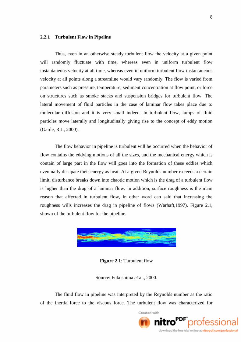
roughness wills increases the drag in pipeline of flows (Warhaft,1997). Figure 2.1,
shown of the turbulent flow for the pipeline.
Figure 2.1: Turbulent flow
Source: Fukushima et al., 2000.
The fluid flow in pipeline was interpreted by the Reynolds number as the ratio
of the inertia force to the viscous force. The turbulent flow was characterized for

9
unsteady eddying motions that are in constant motion with respect to each other. Eddy
can be defined as a large group of fluid particles which move laterally or longitudinally
in the flow field; while undergoing this motion and eddy can change its shape or stretch,
rotate or break into two more eddies. Eddies are generated in the region of high shear in
the mean flow field that is the near the boundary in a pipe or channel flow, in the
vicinity of interface between two streams flowing at different velocities and parallel to
one another.
Therefore, turbulent flow can be considered to consist of the mean motion
superimposed on which are the randomly varying components of velocity in all the
three directions. A similar statement can be made about other variables. At pipeline
flow, eddies that produce in fluctuations in the flow velocity and pressure. When
measured the stream wise velocity in turbulent pipe flow, we would see a variation in
time (Warhaft,1997).
2.2.2 Eddies
Eddies that formed in pipeline of water flow will be interacting with each other
as they move to surrounding, and it will be exchange to the momentum and energy. An
eddy that found in centerline of the pipe will have a relatively high velocity and move
towards to the wall pipeline and interact with eddies that found in the wall, which is
typically have lower velocities. As they mix, the momentum differences are smoothed
out from the pipeline. This process is superficially similar to the action of viscosity,
which tends to smooth out momentum gradients by molecular interactions, and
turbulent flows are sometimes can said as to have an equivalent eddy viscosity. The
eddy viscosity is in typical order of magnitude that larger than the molecular viscosity
will form the turbulent mixing is such an effective transport process (Hunt,
Morrison,2000).
At high shear, which is analogous to saying that at the high Reynolds Number,
the size of larger eddies is governed by the size of flow and its geometry. At given time
of flow contains eddies of various sizes. The largest eddy will be of the size of flows
that is the pipe diameter or flow depth in a channel, whereas the smallest eddy will be
10
very small, say of the order of millimeter. However, it may be emphasized that the size
of the smallest eddy is still sufficiently large compared to the size of molecules of the
fluid. These eddies are dimensional in nature, even though flow may be two
dimensional. Eddies of various sizes are embedded in each other and are impermanent
in nature. That is larger eddies, which are continually formed, break into smaller eddies
until they are finally dissipated through viscous shear (Garde, R.J., 2000).
If the flow field, passage of smallest which is the small and large eddies through
this point would induce velocity fluctuations of small magnitude and large frequency
and of large magnitude and small frequency. This would yield a fluctuations velocity
field. Since the turbulent eddies break into smaller and still smaller eddies which
ultimately die out due to viscous dissipation, the kinetic energy associated with the eddy
reduces. If this secondary motion of eddies is to be maintained at a quasi steady state,
then there must be some mechanism which supplies energy to the secondary motion at
the same rate at which its energy is dissipated. This energy supply is obtained from the
mean flow through mechanism which requires existence of measurable mean shear. At
last the turbulent flow is dependence of the eddying current which is cause from
velocity and pressure (Garde, R.J., 2000).
2.2.3 Drag Force in Pipeline Flow
The liquids or fluids that pass through in a pipeline was experiences drag which
is called as the net force in the direction of flow due to pressure and shear stress forces
that forms in between surface of the object and the flow of fluids in pipeline. The
transportable quantities related to flow, such as momentum, heat, sediment or other
pollutants spread much more rapidly in turbulent flow than in laminar flow. This ability
is several hundred times greater in turbulent flow than in laminar flow. Greater ability
for diffusion is beneficial in many cases and harmful in others (Garde, R.J., 2000).
Moreover, the suspended solids in water will cause the drag force in the pipeline
because the flow behaviours of water were created eddies current which is can distract
the flow of water in pipeline (Frank Kreith,1999).
11
2.3 DRAG REDUCTION
Drag reduction is the effect of turbulent flows. However, drag is an undesirable
effect but it can also be desirable effect, because depending on the application. Drag
reduction is closely associated with the reduction of fuel consumption in automobiles,
submarines, and aircraft, improved safety and durability of structures subjected to high
winds, and reduction of noise and vibration. The application is applied in parachute
activity. Drag or known as frictional pressure drop is a result of the resistance
encountered by flowing fluid being exposed to solid surface, example as pipe wall.
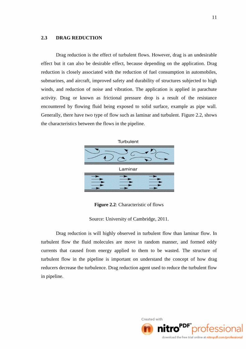
Generally, there have two type of flow such as laminar and turbulent. Figure 2.2, shows
the characteristics between the flows in the pipeline.
Figure 2.2: Characteristic of flows
Source: University of Cambridge, 2011.
Drag reduction is will highly observed in turbulent flow than laminar flow. In
turbulent flow the fluid molecules are move in random manner, and formed eddy
currents that caused from energy applied to them to be wasted. The structure of
turbulent flow in the pipeline is important on understand the concept of how drag
reducers decrease the turbulence. Drag reduction agent used to reduce the turbulent flow
in pipeline.

12
2.3.1 Drag Reduction Agent
The drag reduction agent is the additives that used for reduce the frictional force
in turbulent flow of pipeline with low concentration and pure solvent. The drag
reduction agents are classified into three types of additives such as fibre, polymer, and
suspended solids particle. These are the approach used to save the pumping power
consumption in pipeline.
I. Fiber for Drag Reduction
Drag reducing fibers are the safest and cheapest drag reducing agent compare to
surfactants and polymers. Moreover, some of the surfactant caused problem to the
environment in high consumption. The solubility condition for any material to be
classified as drag reducing agent is not dominating factor was proved in journal of
Abdul Barri.et.al (2009).
Analysis of the fiber induced drag reduction in turbulent wall bounded flows
using more sophisticated rheological models of fiber suspensions has become possible
in less than a decade. Manhart, (2003) has proposed a direct Monte-Carlo solver for
fiber orientation dynamics and used it in one-way coupled simulations of a turbulent
channel flow to study the effect of Brownian diffusivity and fiber aspect ratio on the
non-Newtonian stress generated by fibers.
Two ways coupled simulations have been performed for the first time by
Paschkewitz et al. (2004, 2005) in turbulent channel and boundary-layer flows. They
have used the moment approximation approach along with the hybrid and invariant
based optimal fitting (IBOF) moment closure models. They have demonstrated that
non-Brownian fibers lead to the highest amount of drag reduction as compared to
Brownian fibers. This result is in favour of the conjecture that viscous effects are mainly
responsible for drag reduction by fibers. Note that, in case of fibers, the elasticity is
associated with the rotary Brownian motion (Manhart, 2004).
13
Later, Gillissen et al. (2007, 2007) have also performed simulations by using the
moment approximation approach along with the eigenvalue-based optimal fitting
(EBOF) closure model. It should be noted here that the moment approximation
approach offers a computational reduction in comparison to the direct approach.
However, it requires the use of a moment closure model. Thus, the accuracy of the
simulation depends on the accuracy of the used moment closure model.
II. Surfactant for Drag Reduction
Many cationic surfactants with organic counterions such Salicylate are excellent
drag reducers in aqueous systems. Organic anions are generally introduced as
counterions by the addition of Sodium Salts such as Sodium Salicylate to quaternary
ammonium salts. The counterion to surfactant concentration ratio has a major impact on
drag reduction, rheological behaviour, and the microstructure of some cationic
surfactant or counterion solutions. In dilute solution, drag reducing effectiveness
increases with increase in counterion or surfactant ratio because longer thread-like
micelles form after increased neutralization of the positive charges on the surfactant
head groups by the negative charges of the counterion molecules. While equal molar
counterion molecules are enough to neutralize all or nearly all charges, excess
counterion increases the drag reducing effectiveness (Lin et at, 2000).
Hartmann et al. investigated the thread-like micellar systems of 0.05M CTAB
with various concentrations of Sodium Tosylate (NaTos). Shear thickening occurred in
a very limited domain when _<0.38. For higher concentrations of NaTos, they found a
Newtonian domain followed by shear thinning. In the presence of high counterion
concentration, branching or connection of the micelles can be expected due to
electrostatic shielding of the repulsion between polar heads. Several groups have shown
clearly the presence of branches of the thread-like micelles in such systems.
Lin et al., 1998, investigated the counterion to surfactant concentration ratio on
the drag reduction, rheology and microstructure of the systems Arquad 16/50 (5 mM)
with the 3, 4-dichiorobenzoate counterion at concentrations of 5, 7.5, and 10 mM that is,
with values of 1, 1.5, and 2. With increase in counterion concentration, viscoelasticity

14
as measured by the first normal stress value, decreased due to changes in microstructure
from thread like micelles to vesicles and spherical micelles, although all systems
showed good drag reduction over wide temperature ranges from 20°C to 70°C and from
20°C to 85°C.
Gonzales et al., 2011, proposed that, it had been studied the effects of a
surfactant additive and its dissolution in diesel, on the tribological and rheological
properties of water-based fluids (WBFs) formulated with two weighting materials such
as hematite and calcium carbonate. The tribological properties were established by
measuring the coefficient of friction in conjunction with optical surface profilometry
used to evaluate the wear behaviour. The surfactant studied is a non-ionic/anionic
mixture (80/20). The work presented has three important sections; first, the interactions
between surfactant and the solids particles in aqueous media are discussed on the basis
of conventional measurements, such as dispersion stability and zeta potential. Then, a
brief description of the effect of surfactant on the rheological properties of the drilling
fluid formulations is presented. Finally, the effect of surfactant on the tribological
properties of water based fluids is discussed on the basis of friction reduction and wear
behaviour.
During the last years, petroleum industry has increased the use of directional
drilling techniques due to the need to reach new wellbores in order to maintain world’s
crude oil production. Additionally, there is a tendency to use drilling water based fluid
instead of oil based fluid due to environmental restrictions (Orszulik, 2008 and Clark
1998). Therefore, it is necessary to develop new lubricant additives for water based
drilling fluids with the following characteristic: high performance reducing friction at
low concentration, compatible with drilling fluid additives, able to support drilling
conditions, low toxicity and environmentally safe. It has been found that surfactants
could accomplish this task.
The viscosity was determined as a function of shear rate in the interval 0.1–1000
s−1
. Additionally, light scattering techniques were performed to study the dispersion
stability of solid particles of weighting materials in the aqueous surfactant solutions, and
to correlate the solid surfactant interactions observed with the tribological and

15
rheological properties of water based fluids. Based on the results, it was established that
the evaluated surfactant additive can reduce significantly the coefficient of friction
independently of the weighting materials used, and that suspended additives formulation
has a superior performance in coefficient of friction reduction than dissolution in oil.
Concerning the rheological properties, it was observed a viscosity increase in the
polymeric water based fluids formulated with hematite and suspended additives,
indicating strong interactions in the polymer surfactant solid system (Gonzales et al.,
2011).
Ferhat and Sylvain (2010) are stated that, many surfactants and polymers are
considered as excellent drag reducing agents. This is the phenomenon to induce a
significant head loss reduction compared to the pure solvent. In this study, an aqueous
solution of CetylTrimethyl Ammonium Chloride, (CTAC) and Sodium Salicylate,
(NaSal) are used in turbulent pipe flow system. Drag reduction experiments were
carried out for different experimental conditions using pressure drop measurements. At
the same time, the spatial velocity distribution was measured and analyzed using
particle image velocimetry (PIV).
III. Polymer for Drag Reduction
Toms on 1948 states that the drag reduction phenomenon and observed that the
addition of a few parts per million of long chain polymers in a turbulent flow which is
produced a dramatic reduction of the friction drag. Lumley (1969, 1977) postulated that
in regions of the flow field where polymer molecules are elongated, viscosity is strongly
enhanced. He further postulated that elongation of polymer molecules is due to strain
flow of the elongation flow component, and that vortices diminishes polymer elongation
because it reduces the relative time that the elongated polymer is aligned with the
principal axis of the strain field.
Since in highly turbulent flow regions vortices and strain rate are not correlated,
he concluded that stretched polymer molecules would be found in the overlap layer, but
not in the viscous wall layer. Hence, increased viscosity will occur only in the overlap
layer, enhancing dissipation of turbulent fluctuations, leading to suppression of